

Page 1
Technical Bulletin No. RTB-014
SUBJECT: Heat-Damaged Fusing Connector DATE: Jan. 31, ’91
PAGE: 1 of 1
PREPARED BY: M. Kitajima
CHECKED BY:
CLASSIFICATION:
Action Required
Troubleshooting
Retrofit Information
Symptom
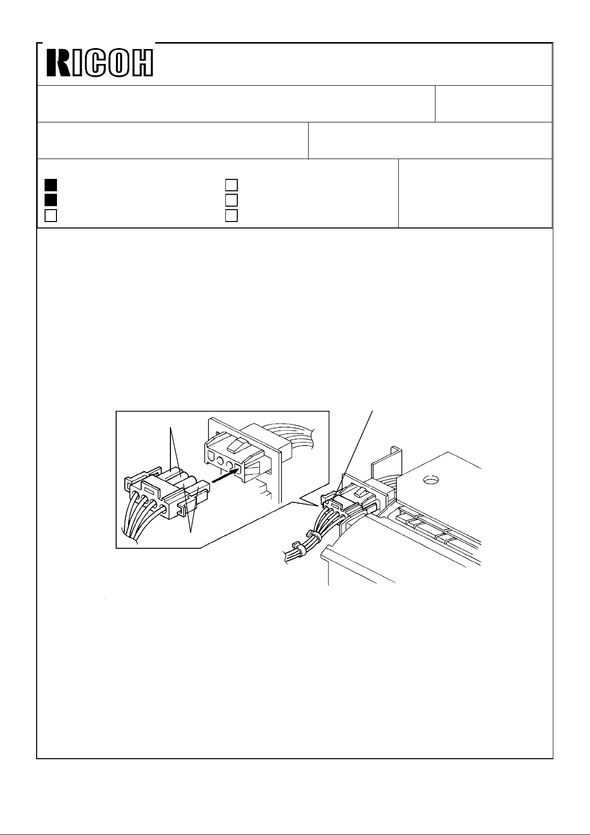
The fusing connector is damaged by electrical arcing.
Cause
When the fusing connector (4P) [A] is loose or the pins of the fusing connector are
corroded, the resistance of the connected pins is increased. Arcing occurs between the
pins on the connectors and the two 11A pins [B] (red line for 11A and white line for 5.5A
[C]) are damaged as the result of excessive current.
[C]
Revision of service manual
Information only
Other
FROM: Copier Technical Support Group
MODEL: F21
[A]
[B]
Countermeasure
Make sure that the fusing connectors are plugged together securely.
On the production machine, a second line has been added to supply power to the 1100W
fusing lamp. The electric current carried by each wire is now 5.5A. (With only one wire,
the wire had to carry an 11A current to the 1100W fusing lamp.) For details, please see
F21 MB No.36 issued on Nov. 30, 1990.
Page 2
Technical Bulletin No. RTB-015
SUBJECT: Malfunction in sort mode DATE: Feb. 28, ’91
PAGE: 1 of 1
PREPARED BY: Takaharu Okajima
CHECKED BY:
CLASSIFICATION:
Action Required
Troubleshooting
Retrofit Information
1. Phenomenon
In sorting mode, the Interrupt key and the Mode Clear key are pressed on sequence, the
following malfunctions occur:
1) A sorter misfeed will be falsely indicated when the paper is fed out to the prooftray.
2) If the Operator opens and closes the front cover to reset the machine and then starts
copying, the first copy is fed out to the 1st bin.
1) and 2) will continue to occur until the main switch is turned off.
2. Countermeasure
Revision of service manual
Information only
Other
FROM: Copier Technical Support Group
MODEL: F21
The software in the EPROMs has been changed to solve this problem.
3. Cut in numbers
New EPROM part number;
P/N A029 6211C : EPROM - 0
P/N A029 6212D : EPROM - 1 - LT
P/N A029 6222C : EPROM - 1 - A4
Cut in serial numbers;
A029 - 11 : 102XXXX
A029 - 12 : 103XXXX
A029 - 14 : 7110300XXX
A029 - 15 : 7110100XXX
A029 - 16 : 12110100001
A029 - 17 : 2471030001
A029 - 25 : 12010100001
A029 - 26 : 3820310001
A029 - 27 : 2471010XXX
Page 3
Technical Bulletin No. RTB-016
SUBJECT: Platinum Corona Wire DATE: Apr. 15, ’91
PAGE: 1 of 2
PREPARED BY: H. Kobayashi
CHECKED BY:
CLASSIFICATION:
Action Required
Troubleshooting
Retrofit Information
The following platinum corona wires have been registered as service parts. The tungsten
corona wires are currently being installed on the assembly line, but they may be replaced
in the field with the platinum corona wires, if desired.
Platinum
corona P/N
#52199540 Corona Wire (1 pc/set) #52199101
#A0079540 Main Corona Wire (1 pc/set) #A0089001
#A0079541 PQC Corona Wire (1 pc/set) #A0079002
#A0079542 Transfer Corona Wire (1 pc/set) #A0079003
Revision of service manual
Information only
Other
Description Current Tungsten Corona P/N
FROM:Copier Technical Support Section
MODEL: F21
The platinum and the tungsten corona wires are fairly similar in performance and handling;
however, there are the following differences:
Point 1
During the copy cycle, less foreign matter (toner, dust, gas) will build up on the surface of
a platinum corona wire than on a tungsten wire. Consequently, platinum corona wires do
not need to be cleaned as often to maintain copy quality. This is true for both these
platinum corona wires and the third vendor’s platinum corona wires.
Point 2
Negative charges cause portions of the surface of a platinum corona wire to break off,
affecting the copy image and requiring replacement of the wire. A platinum wire cannot be
used as a negative charge corona. (A tungsten wire can be used as a negative charge
corona wire.) This is true for both these platinum corona wires and the third vendor’s
platinum corona wires.
Page 4
Technical Bulletin No. RTB-016
SUBJECT: Platinum Corona Wire DATE: Apr. 15, ’91
PAGE: 2 of 2
--When to install the platinum corona wires-
The platinum corona wires do not have to be cleaned as often as the tungsten wires
(point 1). For this reason, the platinum corona wires are most suitable in cases where a
machine is installed in a relatively inaccessible location (far from a service center) and
service calls are difficult to make.
The platinum wires can be installed in the field on the following models:
Model Main Transfer PQC PCC Separation PTC
F20
F21
F22
F30
F31
F33
F34
F40
#52199540 #52199540 #52199540 Negative
charge.
Do not use.
#A0079540 #A0079542 #A0079541 Negative
charge.
Do not use.
Negative
charge.
Do not use.
Negative
charge.
Do not use.
Negative
charge.
Do not use.
Not used.
Note 1
When installing the platinum corona wires, please take the following actions:
1. Clean the corona casings, end blocks, and new platinum wires with damp cloth.
2. Confirm VSG.
Note 2
#A0079540 can also be used as the F90 main corona wire.
Page 5
Technical Bulletin No. RTB-017
SUBJECT: Sorter /sorter stapler installation as a 20 bin, or 40 bin
system
PREPARED BY: I. Kakegawa
CHECKED BY:
CLASSIFICATION:
Action Required
Troubleshooting
Retrofit Information
This RTB clarifies installation of the sorter, sorter stapler, and connector units on the F20,
F21, and F22. Both 20bin and 40 bin systems are covered.
Because the F20, F21, and F22 copy at different speeds, the main PCB ROM on the old
sorter or sorter stapler must be replaced on some types of systems. Therefore, please
read this RTB carefully for F20/F21/F22 system installation.
1. TYPES OF SYSTEM
There are 8 types of F20/F21/F22 systems:
[Sorter System]
Revision of service manual
Information only
Other
FROM: Copier Technical Support Sec.
MODEL: F21
(Same RTB for F22--No.11 and
F20--No.28 are issued.)
DATE: July 15,’90
PAGE: 1 of 8
1) F20 or F21 + one sorter (20 bins) ....................No special action needed.
*2) F20 or F21 + two sorters (40 bins)....................See page 2 and 3.
3) F22 + one sorter (20 bins).................................No special action needed.
*4) F22 + two sorters (40 bins) ...............................See page 2 and 4.
[Sorter Stapler System]
1) F21 + one sorter stapler (20 bins).....................No special action needed.
*2) F21 + two sorter staplers (40 bins)....................See page 5 and 6.
*3) F22 + one sorter stapler (20 bins) .....................See page 5 and 7.
*4) F22 + two sorter staplers (40 bins)....................See page 5 and 8.
NOTE: Systems marked * need to have the ROM replaced if the old sorter or old sorter
stapler is used. Pay special attention to these systems.
Page 6
Technical Bulletin No. RTB-017
SUBJECT: Sorter /sorter stapler installation as a 20 bin, or 40 bin
system
DATE: July 15,’90
PAGE: 2 of 8
2. SORTER SYSTEM
2--1. Modification history for two sorters and connector unit
Model Code Sorter: 5937 -- Sorter: A462 -- Sorter Connector
Unit: 5946 --
Model Name
P/N for
the sorter
ROM
Ricoh CS2060 for F20
Infotec sorter 9060 for F20
Nashua D820 for
F20/21/22.
Savin FS65 for F20/21.
Pitney Bowes D820 for
F20/21
Ricoh CS 2065 for F21/F22
Infotec Sorter 9165 for
F21/22
Savin Sorter for F22
Sorter Connector unit, type A.
Type 1 P/N 59375603 No production No production
Modification (1)
No sorter ROM enclosed in
the accessary box.
One piece of ROM with P/N
59375613 "G" is enclosed.
Type 2
P/N 59375613
from no suffi to "F"
Modification (2) Modification (3)
P/N 59375613
from no suffix to "F"
Type 3 P/N 59375613 "G" P/N 59375613 "G"
Modification (4)
NOTE:
Modification (1) is to adapt the F20/F21 with a 40 bin system from type 2 ROM.
Modification (2) and (3) are to adapt the F22 with a 40 bin system from type 3 ROM.
Modification (4) is to adapt the F22 with a 40 bin system even if old sorters
(type 1, or 2) in stock are used.
As you can see from the above table, there are:
•Three types of sorters for model code 5937
•Two types of sorters for model code A462
•Two types of connector units.
Page 7
Technical Bulletin No. RTB-017
SUBJECT: Sorter /sorter stapler installation as a 20 bin, or 40 bin
system
DATE: July 15,’90
PAGE: 3 of 8
2--2. Necessary action by type of sorter system
[F20 or F21 + two sorters + connector unit (40 bins)]
With this type of system, the action required differs depending on the type of ROM on the
sorter main PCB and by type of the connector unit.
So, please check the part number of ROM and the serial number of the sorter and
connector unit. Then, you can know the type (old or new) of your sorter and connector
unit. For each type, please refer to page 2.
Sorter
[Cut-in serial number for modification (1)]
(From August, ’86 production onward.)
(See Modification (1) )
Old
(Type 1)
Sorter
Connector
Unit
5946--17 Ricoh USA
5946--27 Ricoh Europe
Nashua Europe
5946--27 Infotec 3441200001
Old
(Type 2)
New
(Type 3)
[Cut-in serial number for modification (4)
(From December, ’90 production onward)
Model S/N
Savin
Pitney Bowes
[A] [C]
[B] [D]
(Type 2 and 3)
21105xxxxx
2101200505
New
5937-11(Pitney Bowes) 6080001
5937-15 (Savin) 9460800025
5937-17 (Ricoh, USA) 1660800075
5937-25 (Nashua) 9260800002
5937-26 (Infotec) from first
5937-27 (Ricoh Europe) 1660800036
A462- all models from first
Model S/N
production
production
[A]: Old sorter (Type 1) + Old connector unit (Type 2).
The old ROM (P/N 59375603) on the first sorter main PCB should be replaced with
a new ROM. P/N 59375613, (no suffix or any suffix from A to G) is acceptable.
The ROM is not included, so please prepare one before installation.
[B]: Old sorter (Type 1) + New connector unit (Type 3).
The old ROM (P/N 59375603) on the first sorter main PCB should be replaced with
a new ROM (P/N 59375613G) enclosed in the carton box of the new connector
unit.
[C]: New sorter (Type 2 or 3) + Old connector unit (Type 2).
Since the sorter has a new ROM for 40 bins system, no action is required.
[D]: New sorter (Type 2 or 3) + New connector unit (Type 3).
No ROM replacement is required.
Page 8

Technical Bulletin No. RTB-017
SUBJECT: Sorter /sorter stapler installation as a 20 bin, or 40 bin
system
DATE: July 15,’90
PAGE: 4 of 8
[F22 + two sorters + connector unit (40 bins)]
With this type of system, the action required differs depending on the type of ROM on the
sorter main PCB and by type of the connector unit.
So, please check the part number of ROM and the serial number of the sorter and
connector unit. Then, you can know the type (old or new) of your sorter and connector
unit. For each type, please refer to page 2.
Sorter
(See Modification (2) and (3))
Old
(Type 1and 2)
Sorter
Connector
Unit
5946--17 Ricoh USA
5946--27 Ricoh Europe
5946--27 Infotec 3441200001
Old
(Type 2)
New
(Type 3)
[Cutrin serial number for modification (4)
(From December, ’90 production onward)
Model S/N
Savin
Nashua Canada
Nashua Europe
[A] [C]
[B] [D]
New
(Type 3)
21105xxxxx
2101200505
[Cut-in serial number for modification (2)
and (3)] (From February or March, ’91 production onward)
Model S/N
5937-11(Pitney Bowes) No production
5937-15 (Savin) 94105xxxxx
5937-17 (Ricoh, USA) No production
5937-25 (Nashua) 9210300859
5937-26 (Infotec) No production
5937-27 (Ricoh Europe) No production
A462-15 (Savin) 385106xxxx
A462-17 (Ricoh, USA) 2451020001
A462-26 (Infotec) 3860410001
A462-27 (Ricoh Europe) 2451020046
[A]: Old sorter (Type 1 or 2) + Old connector unit (Type 2).
The old ROM (P/N 59375603, or P/N 59375613 up to suffer "F") on the first sorter
main PCB should be replaced with a new ROM.(P/N 59375613G),
The new ROM is not included, so please prepare one before installation.
[B]: Old sorter (Type 1 or 2) + New connector unit (Type 3).
The old ROM (P/N 59375603, or P/N 59375613 up to suffix "F") on the first sorter
main PCB should be replaced with a new ROM (P/N 59375613G) enclosed in the
carton box of the new connector unit.
[C]: New sorter (Type 3) + Old connector unit (Type 2).
Since the sorter has a new ROM (P/N 59375613G), no action is required.
[D]: New sorter (Type 3) + New connector unit (Type 3).
No ROM replacement is required.
Page 9

Technical Bulletin No. RTB-017
SUBJECT: Sorter /sorter stapler installation as a 20 bin, or 40 bin
system
3. SORTER STAPLER SYSTEM
3--1. Modification history for sorter stapler and connector unit
Sorter Stapler: A469
Type 1
Type 2
Type 3
NOTE: • Modification (1) is to adapt the F21 with a 40 bin system from type 2 ROM.
ROM P/N 4695102 with
suffix form "B" to "E"
Modification (1)
ROM P/N A4695103 (No
suffix)
Modification (2)
ROM P/N A4695103 "A" or
"B"
Serter Stapler Connector
Unit: A310
No Production
Two pieces of ROM with
P/N A3105106A are
enclosed.
Modification (3)
ROM P/N A4695103A or B
DATE: July 15,’90
PAGE: 5 of 8
• Modification (2) is to adapt the F22 with either a 20 bin or a 40 bin system from
type 3 ROM.
• Accessory ROMs (P/N A3105106A) in the connector unit (type 2) are used
when the old sorter staplers (type 1) are installed on the F21 as a 40 bin
system.
(P/N A3105106A has the same program as P/N A4695103 with no suffix.)
• Modification (3) is to adapt the F22 with a 40 bin system even if old sorters
(type 1 and 2) are used.
As you can see from the above table, there are ;
•Three types of sorter staplers
•Two types of connector units
Page 10

Technical Bulletin No. RTB-017
SUBJECT: Sorter /sorter stapler installation as a 20 bin, or 40 bin
system
DATE: July 15,’90
PAGE: 6 of 8
3--2. Necessary action by type of sorter stapler system
[F21 + two sorter staplers + connector unit (40 bins)]
In this system, an action required is different by type of ROM on the sorter stapler main
PCB and by type of the connector unit.
So, please check the part number of ROM and the serial number of sorter stapler and
connector unit. Then, you can know the type (old or new) for your sorter stapler and
connector unit. For each type, please refer to page 5.
Sorter stapler
Old
(Type 1)
Old
Connector
Unit
A310--17 115V/60Hz 2670100001
A310--27 220, 240V/50Hz 2680100001
(Type 2)
New
(Type 3)
[Cut-in serial number for modification (3)
(From October, ’90 onwards)
Model S/N
[A] [C]
[B] [D]
(Type 2 and 3)
New
[Cut-in serial number for modification (1)]
(From June, ’90 production onward.)
Model S/N
A469-11 (Pitney Bowes) 0060001
A469-15 (Savin) 3120060001
A469-16 (Nashua
Canada)
A469-17 (Ricoh, USA) 2440060001
A469-25 (Nashua Europe) 1220070006
A469-26 (Infotec) 383090xxxx
A469-27 (Ricoh Europe) 2440060342
A469-55 (Savin) From the first
M/B Sorter Stapler No 20
issued on Aug- 31,’90)
1220060001
production
[A]: Old sorter stapler (Type 1) + Old connector unit (Type 2).
The old ROM (P/N A4695102B to E) on the sorter stapler main PCB should be
replaced with the ROMs enclosed in the sorter stapler connector unit (P/N
A3105106A).
[B]: Old sorter stapler (Type 1) + New connector unit (Type 3).
The old ROM (P/N A4695102B to E) on the sorter stapler main PCB should be
replaced with the ROMs enclosed in the sorter stapler connector unit (P/N
A4695103A or B).
[C]: New sorter stapler (Type 2 or 3) + Old connector unit (Type 2).
Since the sorter stapler main PCB already has a new ROM (P/N A4695103), it is
not necessary to replace it.
[D]: New sorter stapler (Type 2 and 3) + Old connector unit (Type 3).
Same as [C].
Page 11

Technical Bulletin No. RTB-017
SUBJECT: Sorter /sorter stapler installation as a 20 bin, or 40 bin
system
[F22 + one sorter stapler (20 bins)]
•See RTB F22 No 5.
•When an old sorter stapler (type 1 and 2) is installed on the F22, a new ROM (P/N
A4695103A or B) is required. Prepare a new ROM and replace the old ROM on the
sorter stapler main PCB (P/N A4695102B to E, or A4695103 with no suffix) with a
new ROM (P/N A4695103A or B, P/N A4695103A or B).
•Cut-in serial number for modification (2)
(From October, ’90 production anward.
Model Name V/Hz Code S/N
Pitney Bowes D962 115V/60 Hz A469-11 011xxxx
Savin 7640 S/F 115V/60 Hz A469-15 3120100001
Nashua SR 4965 115V/60 Hz A469-16 1220100001
Ricoh ST 20 115V/60 Hz A469-17 2440100001
Nashya SR 4965 220, 240V/50 Hz A469-25 1220100006
Infotec S/S 9165 220, 240V/50 Hz A469-26 3831100001
Ricoh ST 20 220, 240V/50 Hz A469-27 2440100001
Savin 9710 S/F 115V/60 Hz A469-55 2820100001
DATE: July 15,’90
PAGE: 7 of 8
From the above S/N, a new ROM (P/N A4695103A) has been used at the
factory.
Page 12

Technical Bulletin No. RTB-017
SUBJECT: Sorter /sorter stapler installation as a 20 bin, or 40 bin
system
[F22 + two sorter staplers + connector unit (40 bins)]
Sorter stapler
Connector
Unit
[Cut-in serial number for modification (3)]
Old
(Type 2)
New
(Type 3)
Old
(Type 1 and 2)
[A] [C]
[B] [D]
New
(Type 3)
Cut-in serial number for
modification (2):
See the table in page 7.
(From October,’90 production onward.)
Model S/N
A310--17 115V/60Hz 2670100001
A310--27 220, 240V/50Hz 2680100001
[A]: Old Sorter stapler (Type 1 and 2) + Old connector unit (Type 2).
Prepare two new ROMs (P/N A4695103A or B) and replace the old ROM on each
sorter stapler main PCB with a new one.
DATE: July 15,’90
PAGE: 8 of 8
[B]: Old sorter stapler (Type 1 and 2) + New connector unit (Type 3).
The old ROM on the sorter stapler main PCB should be replaced with the new
ROM (P/N A4695103A or B) enclosed in the new connector unit.
[C]: New sorter stapler (Type 3) + Old connector unit (Type 2).
Since the sorter stapler has a new ROM (P/N A4695103A or B), the old ROMs
(P/N A3105106A) in the old connector unit should not be used. Keep the original
new ROM on the sorter stapler main PCB.
(If it is replaced, paper jam in the sorter stapler may occur.)
[D]: New sorter stapler (Type 3) + New connector unit (Type 3).
Since the sorter stapler has a new ROM (P/N A4695103A or B), ROM replacement
is not necessary.
NOTE:
You can keep the two new accessory ROMs (P/M A4695103A) for these systems as
spare ROMs ;
•F22 + old sorter stapler (type 1 or 2) for 20 bins, or
•F22 + two old sorter staplers (type 1 or 2) + old connector unit.
Page 13

Technical Bulletin No. RTB-018
SUBJECT: F21/F22+two sorter staplers+menu reader DATE: 30 Sep. ’91
PAGE: 1 of 2
PREPARED BY: T. Okajima
CHECKED BY:
CLASSIFICATION:
Action Required
Troubleshooting
Retrofit Information
1. Summary
We have received reports of a software problem. This problem occurs under the
following condition only.
1) Machine combination
•F21 or F22
•2 sorter staplers (40bins)
•Sorter stapler connector
•Menu reader
Revision of service manual
Information only
Other
FROM: Copier Technical Support Section
MODEL: F21
(Same RTB for F22-013)
2) Mode
When operating the machine by using the menu reader. (the problem does not occur
when using the operation panel).
3) Problem
The problem is that the copy papers are fed into the trays at random
4) Action
When you install the machines above combination, please replace the main ROMs in
the copier with the new one.
Page 14

Technical Bulletin No. RTB-018
SUBJECT: F21/F22+two sorter staplers+menu reder DATE: 30 Sep. ’91
PAGE: 2 of 2
2. New ROMs
Please replace the main ROMs (2 pcs) in the copier with the followings:
F21 115V/60HZ
Label Check Sum
A0296211D Special 84 A529
A0296212E Special 84 DAA3
F21 220, 240V/50HZ
Label Check Sum
A0296211D Special 84 A529
A0296222E Special 84 02A5
F22 115V/60HZ
Label Check Sum
A0587056F Special 82 4A66
A0587057F Special 82 3BA5
F22 220, 240V/50HZ
Label Check Sum
A0587156F Special 82 4A66
A0587157F Special 82 994D
3. Cut-in serial number
The cut-in serial numbers and the production ROM numbers will be sent to you later.
Page 15

Technical Bulletin No. RTB-019
SUBJECT: Software quality improvement DATE: Apr. 30, ’92
PAGE: 1 of 2
PREPARED BY: Takaharu Okajima
CHECKED BY:
CLASSIFICATION:
Action Required
Troubleshooting
Retrofit Information
1. Summary
We have received some reports of this problem and have encountered it independently
as well. So, we have modified the software in the main ROM on the main PCB to solve
the following items:
1) Computer forms are not fed in the CFF mode.
2) SC 1 is displayed by noise.
2. Details
1) CFF mode does not work
Problem
When a computer form is set on the exposure glass, and the DF cover is lowered, and
the start key is pressed, one copy is made but the computer form paper is not fed at all.
Revision of service manual
Information only
Other
FROM: Copier Technical Support Group
MODEL: F21
Cause
The main PCB cannot get the CFF set signal due to electrical noise.
Countermeasure
When a computer form is set in the computer form feeder and the DF cover is lowered,
the main PCB checks the CFF set signal only once. To ensure detection of the set
signal, we have modified the software to check the CFF set signal twice.
2) SC-1 (Exposure)
Problem
SC-1 may occur as a result of electrical noise or some other electrical error but, after
resetting the SC, the machine works well.
Countermeasure
When the main board detects an abnormal signal from the lamp regulator lasting 5 ms or
longer, SC-1 is displayed. The new software extends this detection time from 5 ms to 15
ms, and this reduces the occurrence ratio of the problem.
Page 16

Technical Bulletin No. RTB-019
SUBJECT: Software quality improvement DATE: Apr. 30, ’92
PAGE: 2 of 2
3. Action
For this modification, the ROM’s have been changed to those below.
New ROM for 115 V, 60 HZ model
ROM 0 P/N A0296211D Check sum: 839F
ROM 1 P/N A0296212E Check sum: B16A
New ROM for 220/240 V, 50 HZ model
ROM 0 P/N A0296211D Check sum: 839F
ROM 1 P/N A0296222D Check sum: D96C
However, the software of these ROM’s has been modified again. So, please use the
ROM’s that are described in RTB-020 (F21).
4. Cut-in serial number
MODEL NAME V/HZ DESTINATION CODE SERIAL NUMBER
P.B D964 115/60 USA A029-11 Service Part Only
P.B. D964 115/60 Canada A029-12 Service Part Only
Savin 7640 115/60 Canada A029-14 Service Part Only
Savin 7640 115/60 USA A029-15 7110802934
Nashua 4965 115/60 Canada A029-16 Service Part Only
Ricoh FT7770 115/60 USA A029-17 Service Part Only
Ricoh FT7770 115/60 Canada A029-19 Service Part Only
Nashua 4965 220, 240/50 Europe, etc. A029-25 Service Part Only
Infotec 9165DZ 220, 240/50 Europe A029-26 Service Part Only
Ricoh FT7770 220, 240/50 Europe, etc. A029-27 Service Part Only
Page 17

Technical Bulletin No. RTB-020
SUBJECT: Software improvement DATE: Apr. 30, ’92
PAGE: 1 of 4
PREPARED BY: Takaharu Okajima
CHECKED BY:
CLASSIFICATION:
Action Required
Troubleshooting
Retrofit Information
1. Summary
We have received reports of a software problem. So, we have modified the software in
the main ROM. For details, please read the following carefully:
2. Details
1) F21/F22 + two sorter stapler units + menu reader
Problem
In the combination above, when operating the machine by using the menu reader, the
copies will be sorted into the bins at random. (The problem does not occur when using the
operation panel.)
Action
We have corrected the software.
Revision of service manual
Information only
Other
FROM: Copier Technical Support Group
MODEL: F21
(Same RTB for F22-014)
2) Toner marks
Problem
After multi-copying for a long time, toner marks appear at the position where the pick-off
pawls are located.
Cause
During A4/LT or smaller size multi-copy runs, the pick-off pawls continuously touch the
drum, and the toner around the drum accumulates on the pick-off pawls. After many
copies (depending on the copy image) the toner on the pawls drops on the paper.
On the other hand, when A3 (DLT) paper is used, the pick-off pawls are repeatedly
turned off and on, and the toner will not accumulate on the pawls.
See details, next page.
Page 18

Technical Bulletin No. RTB-020
SUBJECT: Software quality improvement DATE: Apr. 30, ’92
PAGE: 2 of 4
F20/F21/F22
A
Regist. MC
ON
OFF
Depending on
the paper size
B
Pick-off
Pawls Sol.
ModelA(One cycle time for
F20 See table 2 89 ms 800 ms 889 ms
F21 See table 2 90 ms 910 ms 1000 ms
F22 See table 2 141 ms 820 ms 961 ms
ON
OFF
multi-copying)
(Fixed)
(Lead time for pick-off
pawls sol. ON)
1st copy 2nd copy
Depending on
the paper size
B
C
(Fixed) (Fixed) (Fixed)
B
(pick-off pawls sol. ON
C
time)
A
C
Table 1
B + C
Model
F20 1500 952 857 1500 952 857
F21 1463 923 833 1463 938 833
F22 1333 833 811 1333 845 811
A3 A4 A5 DLT LT HLT
A (One cycle time for multi-copying) ms
Table 2
D
D
The pick-off pawls solenoid will be turned on after time "B" from turning on the registration
MC. (Time "B" is fixed by model.) See table 1. The pick-off pawls solenoid is turned on for
time "C" to ensure paper separation. (Time "C" is fixed by model.) Then, this will be turned
off. See table 1. However, during multi-copy run and when one cycle time "A" is shorter
than time "B + C", the pick-off pawls solenoid cannot be turned off. Time "C" is higher
priority than time "B". So, time "B" is cancelled, in this case.
To turn the pick-off pawls solenoid on and off repeatedly, "A" should be 50 ms longer than
"B + C". This is for mechanical reasons.
Page 19

Technical Bulletin No. RTB-020
A
SUBJECT: Software quality improvement DATE: Apr. 30, ’92
PAGE: 3 of 4
3. Countermeasure
2nd copy
Regist. MC
B
Pick-off Pawls Sol.
New ROM: During multi-copy runs, the pick-off pawls solenoid will be off during each
copy cycle for any sizes of copy paper. First, after B ms from turning on the
registration clutch, the pick-off pawls solenoid is turned on. And when the
registration clutch is turned off, the pick-off pawls solenoid is also turned off.
After B msec from turning on the registration clutch, the pick-off pawls
solenoid will be turned on for the next copy.
New ROM Parts number and check sum:
F21 115V version
ROM 0 P/N A0296211E Check sum: A529
ROM 1 P/N A0296212F Check sum: DAA3
F21 220/240V version
ROM 0 P/N A0296211E Check sum: A529
ROM 1 P/N A0296222 ECheck sum: 02A5
F22 115V version
ROM 0 P/N A0587056G Check sum: 4A8C
ROM 1 P/N A0587057G Check sum: 45AB
B
B ; 160 ms
F22 220/240V version
ROM 0 P/N A0587156G Check sum: 4A8C
ROM 1 P/N A0587157G Check sum: A369
4. Action
If you have this problem, replace the ROMs with new one and clean the solenoid shaft
of the pick-off pawls with alchol.
Page 20

Technical Bulletin No. RTB-020
SUBJECT: Software quality improvement DATE: Apr. 30, ’92
PAGE: 4 of 4
5. Cut-in serial number
MODEL NAME V/Hz DESTINATION CODE SERICAL NUMBER
Savin 9710 115/60 USA A058-15 3220301772
Nashua 4172 115/60 Canada A058-16 2521120001
Ricoh FT7870 115/60 USA A058-17 2691120296
Nashua 4172 220, 20/50 Europe A058-25 2511120001
infotec 9172DZ 220, 20/50 Europe A058-26 3A6042XXXX
Ricoh FT7870 220, 20/50 Europe A058-27 2691120441
MODEL NAME V/Hz DESTINATION CODE SERICAL NUMBER
P.B. D964 115/60 USA A029-11 204XXXX
P.B. D964 115/60 Canada A029-12 204XXXX
Savin 7640 115/60 Canada A029-14 712040XXXX
Savin 7640 115/60 USA A029-15 712040XXXX
Nashua 4965 115/60 Canada A029-16 Service Parts only
Ricoh FT7770 115/60 USA A029-17 Service Parts only
Ricoh FT7770 115/60 Canada A029-19 Service Parts only
Nashua 4965 220, 240/50 Europe, etc A029-25 Service Parts only
infotec 9165DZ 220, 240/50 Europe A029-26 382042XXXX
Ricoh FT7770 220, 240/50 Europe, etc A029-27 Service Parts only
Page 21

Technical Bulletin No. RTB-021
*82
*96
*92
SUBJECT: Replacement adjustment for Stapler Unit Component part DATE: Oct. 15, ’93
PAGE: 1 of 3
PREPARED BY: T. Okajima
CHECKED BY:
CLASSIFICATION:
Action Required
Troubleshooting
Retrofit Information
1. Summary
We have registered some component parts of the stapler unit (#AJ011001) at our service
parts center to meet a field request. See MB-28 of the F21 and F22 sorter stapler for
further details.
See the illustration and the part number table that follow. In section 2 of this RTB we
describe the replacement and adjustment of some parts, that you need to pay attention to.
*83
*84
*95
Revision of service manual
Information only
Other
FROM: Technical Support Department
MODEL: F21
Sorter Stapler for F21
*93
*94
*91
*90
*85
*86
*87
*88
*89
Page 22

Technical Bulletin No. RTB-021
SUBJECT: Replacement adjustment for Stapler Unit Component part DATE: Oct. 15, ’93
PAGE: 2 of 3
Parts No. Description Q’ty
A4699502 Spring - Stapler Unit 2 *82 15
A4699503 Clamp - Cartridge Holder 1 *83 15
A4699504 Wire - Cartridge Holder 1 *84 15
A4699505 Motor Gear 1 *85 15
A4699506 Gear 1 1 *86 15
A4699507 Gear 2 1 *87 15
A4699508 Key - Drive Gear 1 *88 15
A4699509 Drive Gear 1 *89 15
A4699510 Gear Holder 1 *90 15
A4699511 Pin - Plate 1 *91 15
A4699512 Face Plate 1 *92 15
A4699513 Drive Plate 1 *93 15
A4699514 Forming Plate 1 *94 15
A4699515 Pin - Cartridge Holder 1 *95 15
A4699516 Roller - Cartridge Holder 1 *96 15
Parts catalog
Index Page
* New Index No.
Page 23

Technical Bulletin No. RTB-021
SUBJECT: Replacement adjustment for Stapler Unit Component part DATE: Oct. 15, ’93
PAGE: 3 of 3
2. Replacement and Adjustment
[A]
[C]
[D]
[B]
1. Remove the stapler unit [A] from the sorter stapler unit.
2. Unhook one side of each spring [B]. Just slide it with flat screw driver as shown.
3. Remove the retaining ring [C] and slide out the cartridge holder pin [D].
[G]
[E]
[H]
[F]
4. Remove the face plate [E], the drive plate [F] and the forming plate [G].
5. When replacing the drive plate [F], the forming plate [G], and the springs [H], make
sure of the following points.
• The cut corners of the drive plate and the forming plate must be located in the
left-upper corner.
• Grease both sides of the drive plate and the forming plate.
(Grease Mobil Temp. 1: P/N 52199300)
• Do not pull the springs [H] too much when hooking then to the face plate.
 Loading...