

Page 1
Technical Bulletin No. RTB-006
SUBJECT: AC Drive Board Schematics DATE: Nov. 15, ’90
PAGE: 1 of 3
PREPARED BY: T. Itoh
CHECKED BY:
CLASSIFICATION:
Action Required
Troubleshooting
Retrofit Information
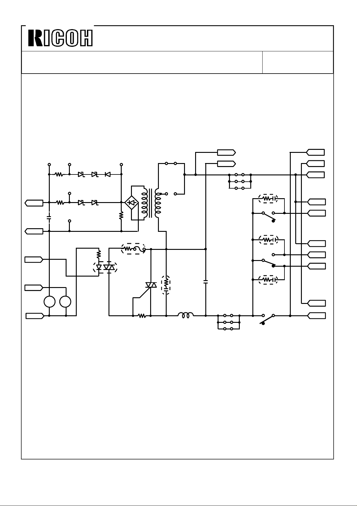
As a permanent countermeasure against electrical malfunction, three noise killers (CR402,
CR403, and CR404)) have been added to the ac drive board circuit. (For the detailed
information of the electrical malfunction, please refer to RTB No. 4.)
The schematics of the ac drive board have been changed as a result of this modification.
See the following pages:
Revision of service manual
Information only
Other
FROM: Copier Technical Support Sec.
MODEL: M210
Page 2
Technical Bulletin No. RTB-006
SUBJECT: AC Drive Board Schematics DATE: Nov. 15, ’90
PAGE: 2 of 3
(For 115V version machines)
Zoom Voltage
CN407-1
C401
0.01
50V
CN407-2
GND
Exposure
Trigger
CN407-3
Main Motor
RA
CN407-4
CN407-5
+24V
TP402
R402
15K 9B2
µ
RA
402
R403
10K
TP403
ZD401 ZD402 D401
TP404
ZD403 ZD404
TP401
1/2W 2.2K
RA
401
R405
9C2
6B35B1
PC401
S22MD3
1S1588
R401
2.4K
TP405
DB401
1B4B42 TR401
R404
1/2W 100
DB402
1J4B42
Ω
TRC401
R406
82
CN406-1
JP403
115V
100V
JP402
CR401
AU1201
Ω
L401
250
µH64
C402
0.1
125V
JP408
JP409
CN406-2
JP405
JP406
µ
JP407
LAMP (H)
LAMP (N)
JP404
CR402
RA401-1
C
CR404
C
CR403
RA402
NO
NC
ND
NO
NO
NC
C
CN401-1
AC (N)
CN401-2
AC (H)
CN401-3
AC (H)
MOTOR (H)
CN402-1
MOTOR (L)
CN402-2
CN403-1
FAN-1 (H)
CN403-2
FAN1-H (N)
CN403-3
FAN1-L (N)
Optics
Anticondensation
Heater (H)
CN405-1
CN405-2
Optics
Anticondensation
Heater (N)
Page 3

Technical Bulletin No. RTB-006
SUBJECT: AC Drive Board Schematics DATE: Nov. 15, ’90
PAGE: 3 of 3
(For 220/240V version machines)
Lamp Voltage
CN407-1
C401
0.01
µ
50V
CN407-2
GND
Temperature
Trigger
CN407-3
Main Motor
RA
CN407-4
CN407-5
+24V
TP402
R402
15K 9B2
R403
10K
RA
402
TP403
ZD401 ZD402 D401
TP404
ZD403 ZD404
5B1 6B4
TP401
1/2W 2.2K
RA
401
R405
9C2
PC401
S22MD3
1S1588
R401
2.4K
TP405
DB401
1B1588 TR401
R404
1/2W 100
Ω
TRC401
R406
82
240V T402
Ω
JP401
220V
T401
CR401
XE1201
L401
800
µH
L402
8mH
C402
0.1
250V
µ
CN406-1
CN406-2
LAMP (H)
LAMP (N)
C403
µ
10
250V
R407
56K
2W
CR402
RA401-1
C
CR404
C
CR403
RA402
NO
NC
NC
NO
ND
C
NO
CN401-1
AC (N)
CN401-2
AC (H)
CN401-3
AC (H)
MOTOR (H)
CN402-1
MOTOR (L)
CN402-2
CN403-1
FAN-1 (H)
CN403-2
FAN1-H (N)
CN403-3
FAN1-L (N)
Optics
Anticondensation
Heater (H)
CN405-1
CN405-2
Optics
Anticondensation
Heater (N)
Page 4

Technical Bulletin No. RTB-007
SUBJECT: To reset original misfeeds in a single step DATE: 30 Sep.’91
PAGE: 1 of 1
PREPARED BY: S. Orita
CHECKED BY:
CLASSIFICATION:
Action Required
Troubleshooting
Retrofit Information
Due to software change for the Japanese version, the part number of the ROM on the DF
main board was changed from A4655160 to A4655180.(See MB No.18 for A465 issued
on March 31,1990.)
However, we found the following problem when P/N A4655180 is installed on the DF main
board.
When an original misfeeds, it is necessary to open and close the DF cover two times to
reset the original misfeed. (The original misfeed cannot be removed by opening and
closing the DF cover only once.)
NOTE: This problem occurs only when the P/N A4655180 is installed on the DF main
and the DF is installed on the M210.
Revision of service manual
Information only
Other
TO: Copier Technical Support Section
MODEL:
M210 ARDF
(A318 and A465)
To prevent this problem, the ROM on the DF main board has been changed.
The part number for the new ROM is A4655185.
Please refer to the MB No.3 for A318.
 Loading...