

Page 1
Technical Bulletin No. RTB-013
SUBJECT: Retrofit for Transfer Current Leakage DATE: Mar.15,1991
PAGE: 1 of 5
PREPARED BY: M.Ishihara
CHECKED BY:
CLASSIFICATION:
Action Required
Troubleshooting
Retrofit Information
1. SYMPTOM
Light or fuzzy image copy appears due to leaking of the transfer corona current.
The red LED on the transfer/separation power pack lights during copying cycles.
2. POSSIBLE CAUSES
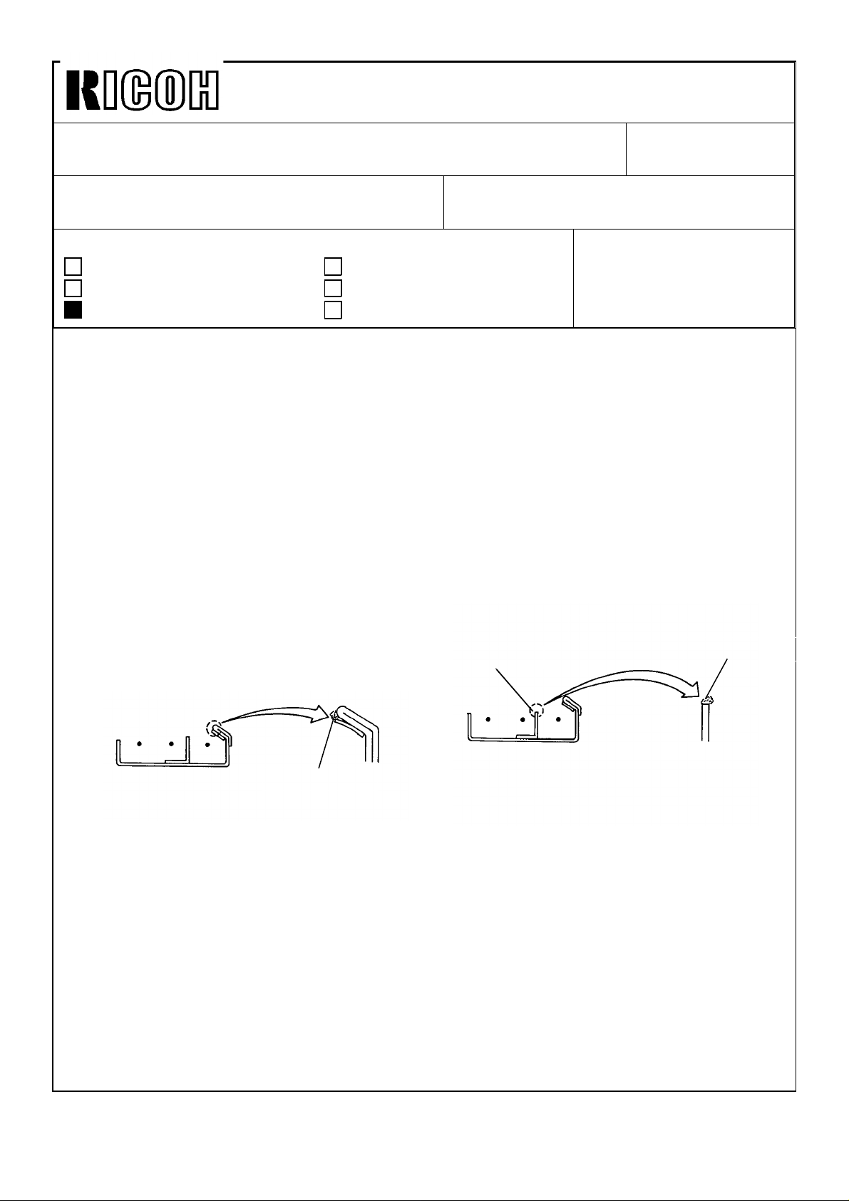
2-1 Foreign matter
There is mylar under the guide plate shown in Fig.1. Glue comes out to the side of the
mylar and foreign matter adheres to this glue. Transfer current leaks from wire to this
foreign matter.
Revision of service manual
Information only
Other
FROM: Copier Tech Support Sec.
MODEL:J1
Fig 1
Rough Edge
Foreign Matter
There is a rough edge at the top of the plate between transfer and separation sections.
(See Fig.2)
A foreign matter sticks to this rough edge and transfer current leaks from wire to this
foreign matter.
2-2 Wire vibration
Wire will always vibrate with a certain amplitude when transfer charge voltage is applied.
Wire amplitude changes depend on wire tension and current frequency. The larger
amplitude becomes the narrower distance between the corona casing and the wire and it
makes easier to leak.
Fig 2
Foreign Matter
Page 2
Technical Bulletin No. RTB-013
SUBJECT: Retrofit for Transfer Current Leakage DATE: Mar.15,1991
PAGE: 2 of 5
3. COUNTERMEASURE
3-1 Retrofit kit parts
P/N. Description
A0239450 T/S Corona Retrofit Kit
Note: A0239450 is arranged as retrofit kit for the specific field. Therefore the kit
(A0239450) is no longer available as service parts but the following component
parts are available as service parts.
Q’ty/Machine P/N Description
1
1
1
1
A0233857
A0233858
AA060124
AD020044
Teflon Tape-13mm
Teflon Tape-6mm
Tension Spring
Corona Wire
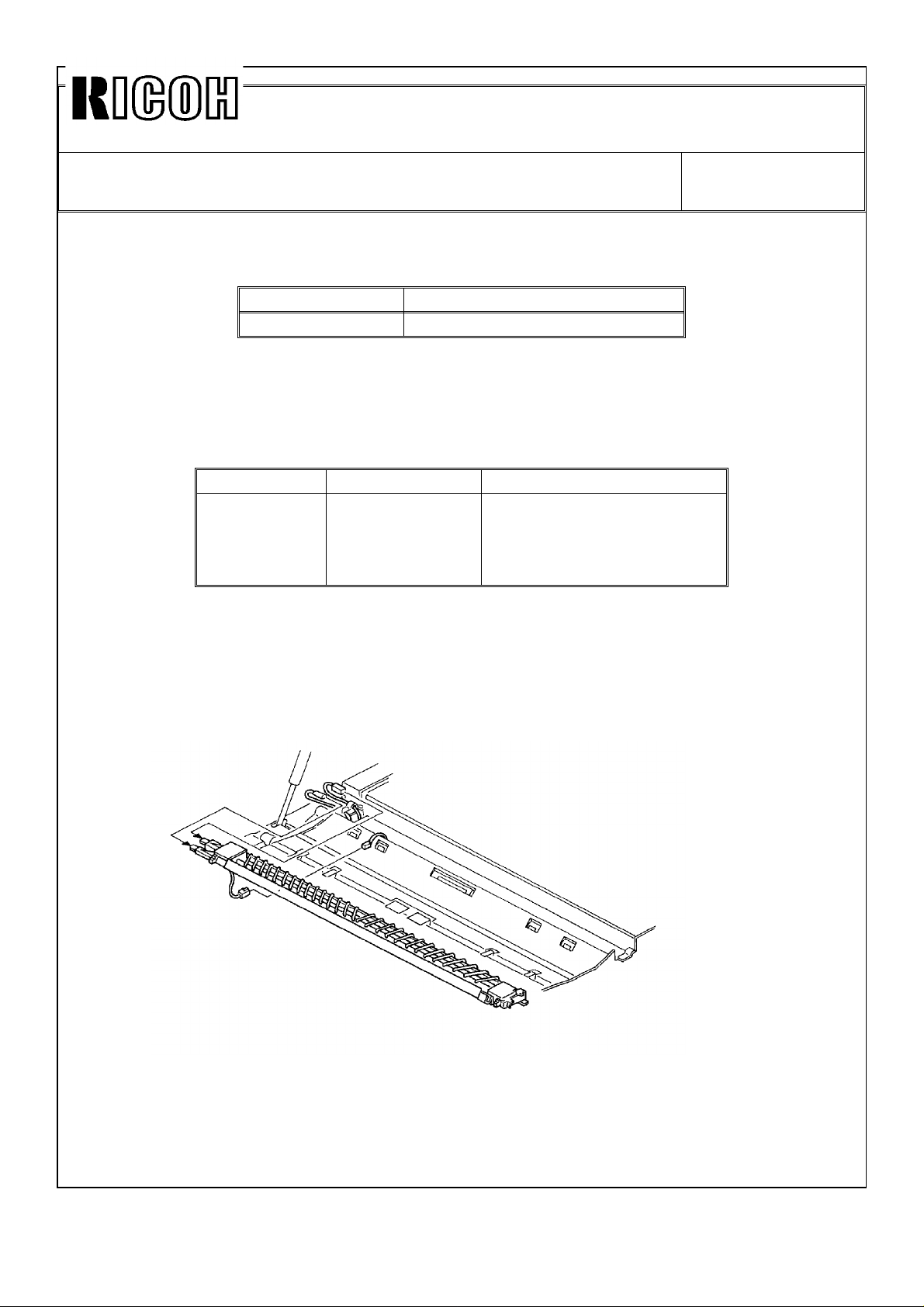
3-2 Procedure for the retrofit parts installation
1. Open the middle unit.
2. Disconnect the connectors of transfer, separation,and ground on the T/S corona unit
and remove the unit from the main frame. (See Fig. 3.)
Fig 3
3. Remove the left and right casing of the corona unit and remove the transfer wire.
Page 3
Technical Bulletin No. RTB-013
SUBJECT: Retrofit for Transfer Current Leakage DATE: Mar.15,1991
PAGE: 3 of 5
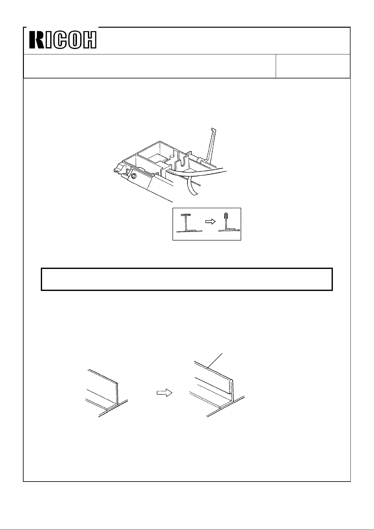
4. Clean the plate between transfer and separation sections with alcohol.
5. Peel off the yellow backing of the 6 mm wide teflon tape (A0233858).
6. Place the center of the teflon tape to the top of the plate between transfer and
separation section. (See Fig. 4.)
Fig 4
7. Stick the tape as shown above. Cover the whole edge between end blocks.
Caution: If the tape is stuck incorrectly,foreign matter may stick to the glue and it is
possible that the leak occurs.
In the future,the plate between transfer and separation sections in the corona unit will be
changed to hemming bent instead of 6 mm wide teflon tape. (See Fig. 5)
Hemming Bent
Fig 5
Page 4
Technical Bulletin No. RTB-013
SUBJECT: Retrofit for Transfer Current Leakage DATE: Mar.15,1991
PAGE: 4 of 5
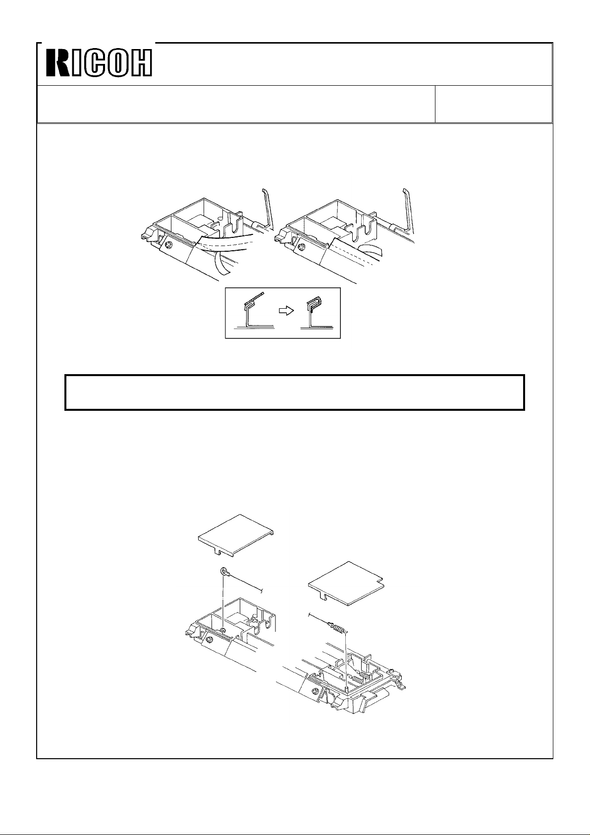
8. Peel off the yellow backing of the 13 mm teflon tape (A0233857) and stick it to the
transfer guide plate as shown in Fig.6.
Fig 6
Caution: Stick the tape evenly. If there is a tape buckle on the upper side of the
guide plate,it is possible that this part touch the drum and will cause damage.
9. To reduce the vibration of the transfer wire, increasing the wire tension is effective.
In order to increase wire tension, we made tighter tension spring and short length type
transfer wire. Also we remove carbon coat on the surface of the transfer wire to
prevent current leakage.
Install the corona wire (AD020044) and the tension spring (AA060124) shown in Fig. 7.
Fig 7
Page 5
Technical Bulletin No. RTB-013
SUBJECT: Retrofit for Transfer Current Leakage DATE: Mar.15,1991
PAGE: 5 of 5
The retrofit parts have been applied to the production machines at the factory as follows.
For. Cut-in Serial Number Starting Month
Ricoh
Bruning
Hoechst
Regma
25601200019360120001667011000128800459-
December,1990
December,1990
December,1990
December,1990
Page 6

Technical Bulletin No. RTB-014
SUBJECT: Technical Information on the Rear Feeder DATE: Mar. 15, ’99
PAGE: 1 of 9
PREPARED BY: M. Ishihara
CHECKED BY:
CLASSIFICATION:
Action Required
Troubleshooting
Retrofit Information
1. SPECIFICATIONS
Size of Original: Maximum: 914 x 3,600 mm
Minimum: 182 x 257 mm
Maximum Passage Width: 1,030 mm
Maximum Thickness of Original: 1 mm
Minimum Thickness of Original: 0.035 mm
Weight: 3.1 kg
Dimensions (W x D x H): 1,350 mm x 120 mm x 60 mm
FROM: Copier technical support section
MODEL: J1
Revision of service manual
Information only
Other
Power Source: +24 volts and +5 volts from the copier
Page 7
Technical Bulletin No. RTB-014
SUBJECT: Technical Information on the Rear Feeder DATE: Mar. 15, ’99
PAGE: 2 of 9
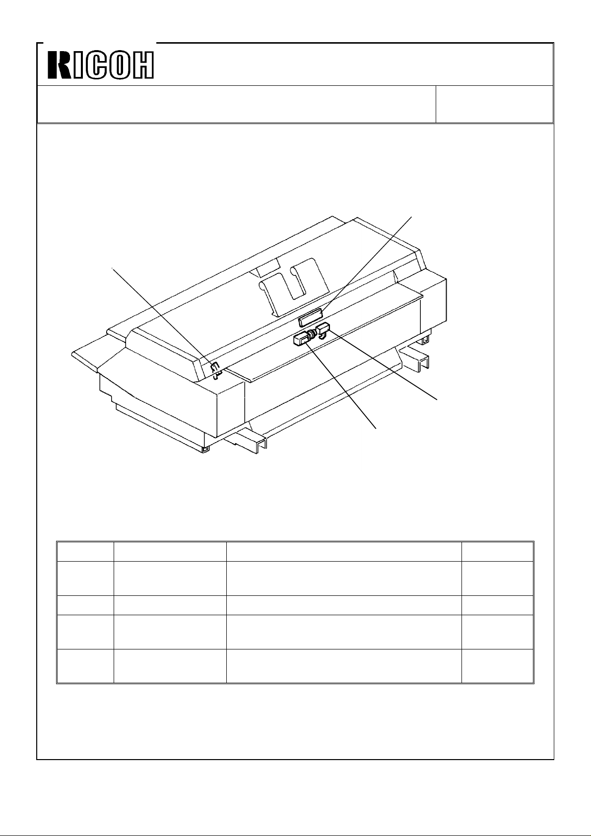
2. ELECTRICAL COMPONENT LAYOUT
4
1
2
3
SYMBOL NAME FUNCTION LOCATION
SW7 Rear Feeder Switch Turns on when the rear feed table is
opened.
S20 Rear Feed Detector Detects when an original is inserted. 2
SOL12 Rear Original
Stopper Solenoid
PCB8 Rear Indicator
Panel
Moves the original stopper down to
prevent an original from being inserted.
Contains the paper and original insertion
indicators and the original stop key.
1
3
4
Page 8

Technical Bulletin No. RTB-014
SUBJECT: Technical Information on the Rear Feeder DATE: Mar. 15, ’99
PAGE: 3 of 9
3. BASIC OPERATION
Basic operation using the rear feeder is same as main copier exept the following points.
1. When the rear feeder opens the rear feeder switch turns on so that the copy exit way
indicator changes from upper way to lower automatically.
2. When the leading edge of the original passes the rear feed detector, the rear original
feed rollers turns and the original is fed straight into the exposure section.
3. When the rear feeder is used, multiple copy cannot be made.
Page 9
Technical Bulletin No. RTB-014
SUBJECT: Technical Information on the Rear Feeder DATE: Mar. 15, ’99
PAGE: 4 of 9
4. INSTALLATION PROCEDURE
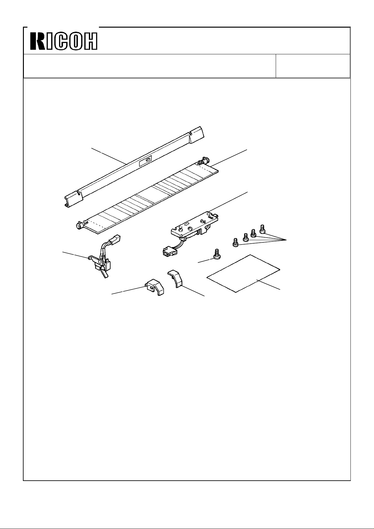
1. ACCESSORY CHECK
1
3
5
Make sure you have all the items listed below.
2
4
8
7
9
6
1. Rear Cover.................................................................................... 1 pc
2. Original Feed Table......................................................................1 pc
3. Microswitch...................................................................................1 pc
4. Original Stopper............................................................................ 1 pc
5. Left Leaf Spring ............................................................................ 1 pc
6. Right Leaf Spring.......................................................................... 1 pc
7. Shoulder Screw ............................................................................ 1 pc
8. Pan Head Screw - M4 x 6............................................................. 4 pcs
9. Installation Procedure................................................................... 1 pc
Page 10
Technical Bulletin No. RTB-014
SUBJECT: Technical Information on the Rear Feeder DATE: Mar. 15, ’99
PAGE: 5 of 9
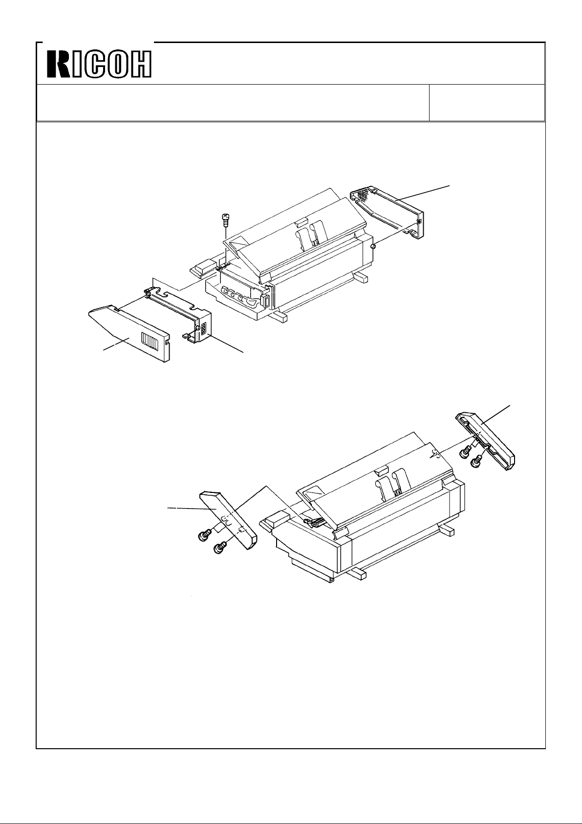
2. INSTALLATION PROCEDURE
[A]
[B]
[C]
[D]
[E]
1. Remove the middle left cover [A] (4 screws).
2. Remove the middle right cover [B] (4 screws).
3. Remove the right horizontal cover [C] (6 screws).
4. Remove the top left cover [D] (4 screws).
5. Remove the top right cover [E] (4 screws).
Page 11

Technical Bulletin No. RTB-014
SUBJECT: Technical Information on the Rear Feeder DATE: Mar. 15, ’99
PAGE: 6 of 9
[A]
6. Remove the rear cover [A] (3 screws).
7. Mount the original stopper [B] (two M4 x 6 screws).
8. Plug in the 2P [C] and 3P [D] connectors.
[B]
[D]
[C]
Page 12

Technical Bulletin No. RTB-014
SUBJECT: Technical Information on the Rear Feeder DATE: Mar. 15, ’99
PAGE: 7 of 9
[B]
[A]
[C]
[D]
9. Mount the microswitch [A] in the upper position as shown (one M4 x 6 screw).
10. Connect the 2P connector [B].
11. Open the original feed unit [C].
12. Mount the left leaf spring [D] (one M4 x 6 screw).
13. Mount the right leaf spring [E] (one M4 x 6 screw).
[E]
Page 13

Technical Bulletin No. RTB-014
SUBJECT: Technical Information on the Rear Feeder DATE: Mar. 15, ’99
PAGE: 8 of 9
[D]
[E]
[C]
[B]
[A]
[G]
[F]
14. Insert pin [A] on the right side of the original feed table [B] into the hole in the frame.
15. Insert the pin [C] on the left side of the table into the frame hole and secure it with a
shoulder screw [D].
16. Apply grease to the left and right leaf springs at the points where they come into contact
with the original feed table.
17. Close the original feed unit.
18. Loosen screw [E] securing the microswitch. Adjust the switch position so that the switch
turns on when the original feed table is opened and turns off when the table is closed.
19. Plug in the 8P connector [F].
20. Mount the rear cover [G] (3 screws).
21. Put back and secure the covers removed in steps 1 -- 5.
Page 14

Technical Bulletin No. RTB-014
SUBJECT: Technical Information on the Rear Feeder DATE: Mar. 15, ’99
PAGE: 9 of 9
5. POINT TO POINT DIAGRAM
Rear Feeder Switch (SW7)
CN106
-A19
-B18
Rear Feeder Detector (S20)
-B19
-B20
-A20
Rear Original Stopper (SOL12)
1
SOL
2
Copier Main Board (PCB1)
[ 0 ↔ 0/5]
Rear Feeder SW
C.GND
[5] VC
C.GND
[ 0/5 → 0]
Rear Feeder Detector
-B8
-A8
[ 24]
Rear Original Stopper
VA [24]
SCN8 [24]
KEY1
LED a
LED b
LED c
LED e
LED f
LED g
CN106
-A14
-A15
-A7
-A6
-A5
-A4
-A3
-A2
CN301
-1
-2
-3
-4
-5
-6
-7
-8
Rear Indicator Panel
(PCB8)
SCAN8
KEY1-SW301/302
a
LED301
LED302
b
c
LED302
e
LED303
LED304
f
g
LED304
Page 15

Technical Bulletin No. RTB-015
SUBJECT: Developer moves to the right or left DATE: July 31,1991
PAGE: 1 of 3
PREPARED BY: M.Ishihara
CHECKED BY:
CLASSIFICATION:
Action Required
Troubleshooting
Retrofit Information
--PROBLEM--
1. Uneven image on copy
2. Service Call condition " Ed "
--CAUSE--
1. Improper machine installation level
2. Excessive developer
2.6 Kg or more of the old developer must be removed from the development tank
when replacing developer with new one.
If there is too much developer in the tank, it moves to the right side and stays in the
the development tank.
Revision of service manual
Information only
Other
FROM: Copier Technical Support Section
MODEL: J1
3. When developer moves to the right or left area, the Toner Density Sensor in the
development tank does not correctly determine toner density. This cause the service
call condition "Ed".
--REMEDY--
1. Adjust and correct the machine level.
2. Remove 500 g of developer from the tank when the developer moves to the right. If
the developer is not replaced, there is no need to remove the developer from the tank.
3. Adjust position of the mylar seals (#A0233095) on the scrapers (#AD036012 and
#AD036013).
Page 16

Technical Bulletin No. RTB-015
SUBJECT: Developer moves to the right or left DATE: July 31,1991
PAGE: 2 of 3
[Adjustment Standard]
1) Factory Setting: A=3.8±0.5mm, B=10±0.5mm
2) In case the developer moves to the right: A=10mm, B=10mm
3) In case the developer moves to the left: A=3mm, B=5mm
Scraper -- B (#AD036012)
Scraper -- C (#AD036013)
A
Mylar Seal -- 15 x 23 (#A0233095)
B
Fig.1
Page 17

Technical Bulletin No. RTB-015
SUBJECT: Developer moves to the right or left DATE: July 31,1991
PAGE: 3 of 3
[Adjustment Procedure]
1) Remove the left and right middle
covers.
(See S/M page 5-1 and 5-2)
2) Open the top unit and the toner
cartridge cover.
Fig.2
3) Remove the toner cartridge and
clean the toner entrance area.
(Fig.2)
4) Remove the screw[A] and push
down the harness guide bracket
[B]. (Fig.3)
5) Remove the development filter. (1
screw)
6) Remove the screws [C,D] fixing
the right side of the toner
cartridge holder (#A0233117).
(Fig.3)
7) Remove the screw [E] fixing the
left side of the toner cartridge
holder. (Fig,4)
8) Remove or cut the left and right
stopper seals (#A0233122,
#A0233121). (Fig.5)
9) Remove the toner cartridge
holder [F].
10) Remove the mylar seals and put
them in their proper position as
shown in Fig.1.
[C]
Fig.4
[D]
[B]
[A]
Fig.3
[E]
Cutter
[F]
11) Before re-assembling the parts
removed,check the developer flow
using the Out Put Test mode No.1
and 2. (See S/M page 4-18) From
the right side confirm that the
shafts of the Paddle Roller
(#AD038009) and the
Development Auger (#AD037003)
turn.
12) Re-assemble the parts removed.
Fig.5
Page 18

Technical Bulletin No. RTB-016
SUBJECT: Fuzzy image on copy DATE: July 31, ’91
PAGE: 1 of 2
PREPARED BY: M. Ishihara
CHECKED BY:
CLASSIFICATION:
Action Required
Troubleshooting
Retrofit Information
-- PROBLEM --
Fuzzy or blurred image appears on copy.
-- CAUSE --
1. T & S corona guide plate (P/N A0233861) is mounted on the corona unit at the lowest
position.
2. The resistance of the copy paper is too high and the transfer current adjusted at the
factory does not match the paper.
-- REMEDY --
1. Adjust the position of the T & S corona guide plate as follows.
1) Measure the distance "A" (between the leading edge of the mylar seal and the edge
of the guide plate) shown in fig 1.
2) loosen two screws fixing the guide plate.
3) Place the guide plate on the corona unit shown in Fig. Adjust the distance [B]
between the edge of the guide plate and the edge of the plate support (on the
corona unit).
Tighten the two screws to determine proper distence.
Refer to the table.
For example, if the distance "A" is measured as 3.5 mm, make the distance "B" 2.5 mm
and tighten two secrews.
Revision of service manual
Information only
Other
FROM: Copier Technical Support Section
MODEL: J1
NOTE: If the plate is fixed at highest position the distance "B" becomes too narrow, and
the drum may be damaged by the plate.
T & S Corona Unit
A B
2.5 mm 3.5 mm
3.0 mm 3.0 mm
3.5 mm 2.5 mm
4.0 mm 2.0 mm
A
A
B
T & S Corona Guide Plate
(P/N A0233861)
Fig. 1
Page 19

Technical Bulletin No. RTB-016
SUBJECT: Fuzzy image on copy DATE: July 31, ’91
PAGE: 2 of 2
2. Reduce the transfer current as follows.
Standard Setting (Factory Setting): T1: DC--150 ± 5 µA
T2: DC--250
-- When using the current measuring drum --
1) Set the current measuring drum in the copier.
(See page 5-13 to 5-15 in Service Manual)
2) Remove the lower rear cover.
3) Reduce the current of T1 and T2 by turning VRs on the T & S power pack as
shown below.
T1: DC--110 µA
T2: DC--210 µA
−10
+5
µA
Lower Rear Cover
(P/N A0231295)
Power Pack - T/S
(P/N AZ320027)
-- When not in use current measuring drum --
1) Obtain the T1 and T2 current using the output mode No. 62 and No. 63 connecting
the digital multi meter leads to the transfer lead and the ground. The current
obtained may be 3 or 4 times as great as standard current.
2) Reduce the current by turning the T1 and T2 VRs on the T & S power pack using
the following formula.
T1 =
A: obtained current of T1
B: obtained current of T2
110
x A, T2 =
150
210
250
x B
Page 20

Technical Bulletin No. RTB-017
SUBJECT: Trailing edge erase margin feature DATE: Aug. 15, ’91
PAGE: 1 of 1
PREPARED BY: M. Ishihara
CHECKED BY: T. Ito
CLASSIFICATION:
Action Required
Troubleshooting
Retrofit Information
Ricoh announced that the formal specification of the erase margin is 5 mm, 10 mm, 15
mm and 20 mm on both the leading trailing edges.
However, the following margin is available for copiers with EPROM version "C" (P/N
A0235732C) onward on the main board.
Mode No.
Erase Margin Indicator 0 1 2 3 4 5 6 7 8 9
LED OFF 0 0 0 0 0 0 0 0 0 0
LED ON at: 5 mm +5 --5 --15 --25 --35 --45 --55 --65 --75 --85
10 mm +10 --10 --20 --30 --40 --50 --60 --70 --80 --90
15 mm +15 --15 --25 --35 --45 --55 --65 --75 --85 --95
Revision of service manual
Information only
Other
FROM: Copier Technical Support Section
MODEL: J1
20 mm +20 --20 --30 --40 --50 --60 --70 --80 --90 --100
-- Procedure for the new margin --
Use SP mode
1. Turn on the DIP SW 101-8 and the main switch.
2. Select the "Auto Image Density".
3. Select the Lead Edge Erase at "5 mm".
4. Press key for desirable mode. See the table.
Ex.
5. Press the copy exit way key to set.
6. Turn off the DIP SW 101-8.
If you select --85 mm, --90 mm, --95 mm, --100 mm, press the key till the
counter indicates "9".
+: Leading Edge Erase Margin
-- : Trailing Edge Erase Margin
Page 21

Technical Bulletin No. RTB-018
SUBJECT: Fusing temperature fixing mode DATE: Aug. 15, ’91
PAGE: 1 of 1
PREPARED BY: M. Ishihara
CHECKED BY: T. Ito
CLASSIFICATION:
Action Required
Troubleshooting
Retrofit Information
To reduce the buckle ( ) on the translucent paper, some examination were
performed at our laboratory and it was found that fixing the fusing temperature at 185°C is
effective.
-- Procedure to fix the temperature at 185°C --
1. Confirm the EPROM on the main board version "C" or later (P/N A0235732C). The
EPROM (A0235732C) has been applied to the July, 1990 mass-production machines
onward.
2. Turn on DIP SW 101-8 and the main switch.
3. Select the manual ID level at 8.
Revision of service manual
Information only
Other
FROM: Copier Technical Support Section
MODEL:
J1
Lighter Copy Indicator
4. Select the Lead Edge Erase Margin at 20 mm.
5. Press the key once to indicate "1" in the copy counter.
6. Press the copy exit way key to set.
7. Turn off DIP SW 101-8.
NOTE: When returning to normal mode, follow the above procedure changing step 5) as
follows.
5) Press the key once to indicate "0" in the copy counter.
Page 22

Technica l Bulletin No . RTB-02 0
SUBJ ECT: DLE DATE: M ay 15, ’93
PAGE: 1 o f 3
PREPARED BY: H . Ko b ayas hi
CHECKED BY:
CLASSIFICATION:
Action Required
Troubleshooting
Retrofit Information
Pheno men on : To ner is su pp lied exc essively and DLE (Vsp / Vsg > 50%) is d isp layed on
the cop y co unter after initial c onditioning when the developer has been
replaced with new developer.
Cause: The surface voltage on drum may sometimes drop due to drum fatigue. This
causes a low density sensor pattern on the drum.
Solution: The ROM software on the main board has been changed as follows (P/N
A0235732D → P/N A0235732E):
The range of the ID sensor grid voltage adjustment has been made wider.
Old ID Sens o r g r id
voltage Adjustment
(SP m o d e # 2 2)
0 -460 -460
1 -380 -400
2 -400 -440
3 -420 -500
4 -440 -540
5 -480 -600
6 -500 -640
New ID Sensor grid
voltage Adjustment
(SP m o d e # 2 2)
Revision of service manual
Information only
Other
FROM: Copier Technical Support Section
MODEL: J1
Page 23

Technica l Bulletin No . RTB-02 0
SUBJ ECT: DLE DATE: M ay 15, ’93
PAGE: 2 o f 3
To reduce the toner supply amount, the toner supply control has been changed as
follows:
Old
Toner Density Sensor
Output (= Vts)
Vts≥ 4.7 Service C all "Ed"
Ton er Near End
Condition
4.7> Vts≥ 3.5 Toner Density sensor
co nt ro l ( Ton er is
supplied)
3.5> Vts≥ 2.2 ID sensor contr ol Vsp/Vsg= 0.225 or
2.2> Vts≥ 1.9 ID sensor control Vsp/Vsg= 0.225 or
1.9> Vts> 1.6 Toner density sensor
control
(no toner supply)
1.6≥ Vts Service Call "Ed"
New: The upper limit has been changed from 1.9 to 2.4. To prevent malfunction of toner
near end c o nd itio n , it is p ro h ib ited un d er t he c o nd itio n (1. 9 ≤ Vts < 2.4).
Toner Density Sensor
Output (= Vts)
Vts ≥ 4.7 Service Call "Ed"
Vsp/ Vsg = 0.225 o r
more is detected by 5
times in a lo w.
more is detected by 5
times in a lo w.
more is detected by
10 tim es in a lo w.
Ton er Near End
Condition
4.7> Vts> 3.5 Toner Density sensor
co nt ro l ( Ton er is
supplied)
3.5≥ Vts≥ 2.4 ID sensor control Vsp/Vsg= 0.225 or more
2.4> Vts > 1.6 Toner density sensor
control
(no toner supply)
1.6≥ Vts Service Call "Ed"
Vsp/ Vsg = 0.225 or mo re
is detected by 5 times in
a low.
is detected by 5 times in
a low.
Page 24

Technica l Bulletin No . RTB-02 0
SUBJ ECT: DLE DATE: M ay 15, ’93
PAGE: 3 o f 3
Action required: When the DLE is displayed in the copy counter after the developer is
replaced. Replace the ROM on the main board with the new one
(P/N: A0235732E).Th en, ch ang e th e ID sens o r g rid vo ltag e fr om
-460 volts to -600 vo lts b y SP mod e # 22 (fr om 0 to 5) .
Perform intial c o nd itio nin g ag ain.
Remarks: When the DLE is displayed on the copy co unter a second time, even after
car ryin g o ut th e abo ve, rep lace t he d ru m wit h a n ew o ne an d retu rn t he ID s enso r
gr id vo ltag e t o -460 volt s b y SP mod e.
This mo d ific atio n h as b een ap p lied to th e pr o d uc tio n m ach ines fro m Ap ril 1993.
Page 25

Technical Bulletin No. RTB-021
SUBJECT: Developer moves to the sides DATE: July 15, ’93
PAGE: 1 of 7
PREPARED BY: H. Kobayashi
CHECKED BY:
CLASSIFICATION:
Action Required
Troubleshooting
Retrofit Information
FROM: Copier Technical Support Section
MODEL: J1
Revision of service manual
Information only
Other
Page 26

Technical Bulletin No. RTB-021
SUBJECT: Developer moves to the sides DATE: July 15, ’93
PAGE: 2 of 7
[1] DEVELOPER LIFE
Cause:
Developer moves to the right due to decreasing fluidity because of the developer has
reached the end of its life.
Developer Life:
K+E: 20,000 – 40,000 copies/D size sideways
Ricoh & Others: 12,000 – 24,000 meters/A1 sideways
Note: Developer life becomes shorter when copying 1 to 1 and the life will be longer when
multi-copying. (The drum life is same as developer.)
Remedy:
Replace developer with new one in the above condition
[2] MIXED DEVELOPER (Old & New)
Cause:
Some amount of old developer remains in the tank when removing it using SP mode only.
Then new one (3 kg) is poured in the tank so that the old and new developer are mixed in
the tank. As a result, the charge ability of the developer does not stay constant and the
fluidity becomes worse. Also the volume of the developer in the tank in creases (3 kg + old
one).
Under these conditions, the developer moves to the right.
Remedy:
1) Remove the old developer using SP mode (See S/M P.5-27, 5- 28)
To remove the old developer as much as possible, place a block of wood or equivalent on
the left side under the copier. (See Fig. 1)
Block of wood or
equivalent
[Fig. 1]
Page 27

Technical Bulletin No. RTB-021
Drum
SUBJECT: Developer moves to the sides DATE: July 15, ’93
PAGE: 3 of 7
2) Move the upper unit up and down several times when the developer seems to be
removed completely after using SP mode to remove the remaining developer in the tank.
(See Fig. 2)
[Fig. 2]
3) Remove the drum.
4) Remove the developer on the development roller (magnetic roller) with a vacuum cleaner
while turning the development motor fin clockwise. (See Fig. 3)
Dev. Motor Fin
[Fig. 3]
5) Re-assemble the parts removed.
6) Pour the new developer (3 kg) in the tank. (See S/M P.3-9, 3-10)
7) Adjust the toner density sensor voltage to 4.0 V. (See S/M P.5-22)
Dev. Roller
Vacuum
Cleaner Drum
8) Perform the initial conditioning (See S/M P.3-12.)
Page 28

Technical Bulletin No. RTB-021
SUBJECT: Developer moves to the sides DATE: July 15, ’93
PAGE: 4 of 7
[3] CHECK FLUIDITY
1) Remove the toner cartridge.
2) Remove the toner cartridge holder (P/N A0233117).
(See Fig. 4)
Toner Cortridge
Holder
[Fig. 4]
3) Make the developer level even using a folded paper, or equivalent, by hand. (See Fig. 5)
Scraper Plate
[Fig. 5]
4) Set "Free run mode". (DIP SW 101-1 ON, Wait for Ready, insert original and pull it back.)
5) Visually check the developer fluidity on the scraper plates.
Page 29

Technical Bulletin No. RTB-021
SUBJECT: Developer moves to the sides DATE: July 15, ’93
PAGE: 5 of 7
[4] FLOATING GROUND
Bias voltage influences the developer fluidity in case of a high copy volume range.
Cause:
A ground wire is connected to the development auger casing (P/N A0233091) and the bias
voltage is applied to the casing during the copying process.
It makes the developer fluidity worse.
Remedy:
1) Remove the right middle cover.
2) Open the main board bracket.
3) Remove the development filter. (See Fig. 6)
[Fig. 6]
4) Remove screw A and the red wire. (See Fig. 7)
5) Remove screw B in Fig. 7 and fix the orange wire together with the red wire at the same
position [C].
6) Fix the screw A only at the same position [D].
[C]
[D]
[B]
Orange Wire
[A]
Red Wire
[Fig. 7]
Page 30

Technical Bulletin No. RTB-021
SUBJECT: Developer moves to the sides DATE: July 15, ’93
PAGE: 6 of 7
[5] AUGER CASING RE-POSITIONING
When the developer moves to the right, try the following procedure.
1) Remove the developer.
2) Remove the toner cartridge holder (P/N A0233117).
3) Remove the left scraper (P/N AD036011). (One screw)
4) Remove the middle and right scrapers (P/N AD036012, A0236013) sliding them to the
left end.
5) Loosen the two screws [A] fixing the auger casing (P/N A0233091). (See Fig. 8)
Auger
Casing
[Fig. 8]
6) Lift the right side of the auger casing with your finger and fix the two screws [A] again.
(See Fig. 8)
This makes the gap between the dev. roller and the casing on the right side a bit wider so
that the developer accumulator on the right side will be broken.
[A]
Page 31

Technical Bulletin No. RTB-021
SUBJECT: Developer moves to the sides DATE: July 15, ’93
PAGE: 7 of 7
[6] ADDITIONAL REMEDY TO THE RTB-015
Even if the developer moves to the right after the adjustment described in RTB-015 is
done, remove the two seals shown in Fig. 9.
[Fig. 9]
[7] MACHINE LEVEL ADJUSTMENT
Check the developer fluidity (See [5]), then loosen the nut [A] and turn the nut [B] to lift the
right side of the machine when developer moves to the right.
[B]
[A]
[Fig. 10]
Page 32

Technical Bulletin No. RTB-022
SUBJECT: Possible poor connection on the terminal block DATE: June 15, ’96
PAGE: 1 of 1
PREPARED BY: A. Sasaki
CHECKED BY:
CLASSIFICATION:
Action Required
Troubleshooting
Retrofit Information
[Symptom]
Possible poor connection of the power supply cables on the terminal block [A]. This
causes the terminal to overheat. However, it does not damage any other parts.
[Cause]
The solder, which is used to fix the wires in the cables firmly, is melted and
deformed and finally a small gap is created between the solder and the fixing screw.
[Action required]
Revision of service manual
Information only
Other
FROM: 1st Field Information Dept. QAC
MODEL: J1
During the next visit, to secure the wires, please tighten all the screws [B] fixing the
power supply cables on the terminal block.
[A]
Rear View
[A]
[B]
 Loading...