

Page 1
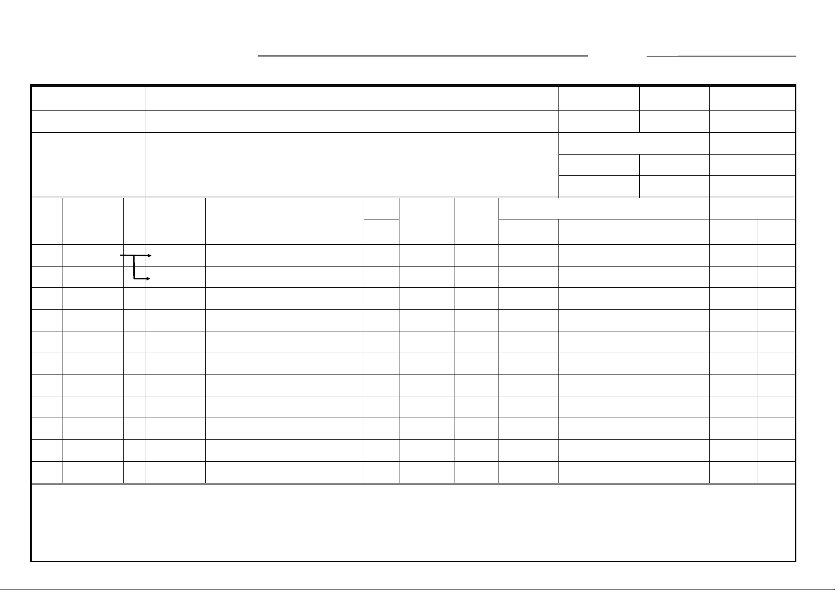
MODIFICATION BULL E TIN NO. 70 Page 1 of 2 ISSUED ON: October 31, ’92
Model V30 Volt/Hz
Mod i fied Article Optic s
Reason for
Modification
Draw
No.
Old Parts
No.
A0001629 A0001629 Wing - Side 5 → 25329
A0421363 A0421364 Left Scale Bracket 1 → 1 X/O * New Index No. 8 29
Date of
Modification
Service Parts Only
To prevent SC22
New Parts
No.
A0521668 Wing - Center 0 → 3 X/O * 66 29
Description
A.B.C.
Rank Part No. Description Index No. Page
Q’ty Used
Old → New
Inter-
change-
ability
Part needed for replacement by new part Parts Catalog
Serial Numbe r
Rank: A : Replace wit h new parts immediately. B : Repl ace with new par t s at time of repair. C : Replace w ith new parts at time of overhaul .
Interchangeability:
(1) W hen old and new parts are not mutually interchangeable, use a dditional parts or an assembly part as indicated in "Parts needed for replacement by new part" to
install the ne w pa rt.
(2) The mark to the left of the sl ash indicates whethe r the old part can be used in the ne w ma chine, and the mark to the right indicates whether the new part can be use d
in the old machine. x = Not interchangeable o = I nterchangea ble
Page 2

MODIFICATION BULL E TIN NO. 70 Page 2 of 2 ISSUED ON: October 31, ’92
DETAILS OF MODIFICATION
When the screws which fix the exposure lamp wings are caught at the edge of the exposure glass, SC22 turns on.
To prevent this, the gap between the exposure glass and the first scanner has been widen by modifying the wings.
Also, the left scale bracket has been modified to minimize the warp.
T. Ito, Man ager
Copier Technical Support
Page 3
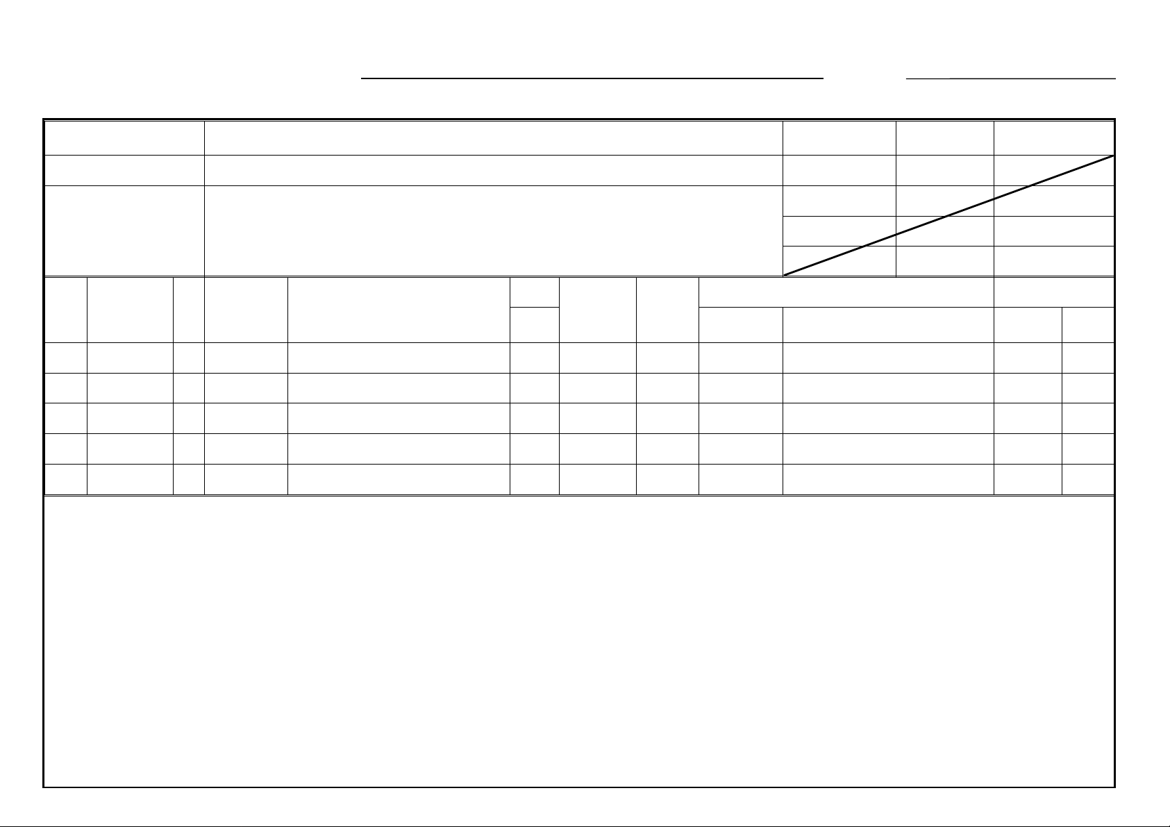
MODIFICATION BULLETIN NO. 71 Page 1 of 1 ISSUED ON: October 31, ’92
Model V30 Volt/Hz
Mod i fied Article Paper Feed Section/ Development Tank Unit
Reason for
Due to part standa rdization
Modification
Draw
No.
Old Parts
No.
A0422710 A0892710 Front Cassette Holder 1 → 1O/O 39 9
A0422715 A0892715 Rear Cassette Holder 1 → 1O/O 69 9
A0422607 A0892607 Relay Sensor Actuator 1 → 1 O/O 32 11
A0002621 A0892621 Upper Guide Plate - Upper Feed 1 → 1 O/O 17 11
A0422635 A0892635 Guide Plate - Cover Feed 1 → 1 O/O 21 11
New Parts
No.
Description
Date of
Modification
A.B.C.
Rank Part No. Description Index No. Page
Q’ty Used
Old → New
Inter-
change-
ability
Part needed for replacement by new part Parts Catalog
Serial Numbe r
T. Ito, Man ager
Copier Technical Support
Page 4

MODIFICATION BULLETIN NO. 72 Page 1 of 2 ISSUED ON: October 31, ’92
Model V30 Volt/Hz
Mod i fied Article Clea ning Unit
Reason for
To minimize a drum scratch when removing a cleaning unit
Modification
Draw
No.
Old Parts
No.
A0523600 A0893601 Cleaning Unit Cas ing 1 → 1 X/O 29 17
AA143001 1 → 0817
AA143002 1 → 02417
AA140005 AA140450 Cleaning Drive Shaft 1 → 1 X/O 14 17
09514014W A0893607 Shoulder Screw 3 → 3 X/O 107 17
New Parts
A0893614 Pressure Bracket 0 → 1 * 48 17
No.
Description
Date of
Modification
Service Parts Only
A.B.C.
Rank Part No. Description Index No. Page
Q’ty Used
Old → New
Inter-
change-
ability
Part needed for replacement by new part Parts Catalog
Serial Numbe r
AA063212 Spring 0 → 1 * 49 17
AA143076 Shoulder Screw 0 → 1 * 50 17
* New Index No.
Rank: A : Replace with new parts immediately. B : Repl ace with new par t s at time of repair. C : Replace w ith new parts at time of overhall.
Interchangeability:
(1) W hen old and new parts are not mutually interchangeable, use a dditional parts or an assembly part as indicated in "Parts needed for replacement by new part" to
install the ne w pa rt.
(2) The mark to the left of the sl ash indicates whethe r the old part can be used in the ne w ma chine, and the mark to the right indicates whether the new part can be use d
in the old machine. x = Not interchangeable o = I nterchangea ble
Page 5

MODIFICATION BULLETIN NO. 72 Page 2 of 2 ISSUED ON: October 31, ’92
DETAILS OF MODIFICATION
To minimize drum scratches when removing the cleaning unit, a cleaning unit release mechanism has been added. When
the drum stay is removed, the pressure bracket on the cleaning unit pushes the guide rail to make a gap between the
pick-off pawls and the drum. In accordance with this modification, the shape of the positioning studs also has been
modified to install the cleaning unit and the drum stay easily.
50
48
49
T. Ito, Man ager
Copier Technical Support
Page 6

MODIFICATION BULLETIN NO. 73 Page 1 of 2 ISSUED ON: October 31, ’92
Model V30 Volt/Hz
Mod i fied Article Optic s
Reason for
Modification
Draw
No.
Old Parts
No.
A0422694 A0892694 Pressure Solenoid Bracket O/O 50 9
A0011650 A0011664 First Scanner O/O 41 29
A0421860 A0891860 Front Optics Frame O/O 19 31
A0421847 A0891848 Lens Housing Plate O/O 24 31
A0521854 A0891854 Front Mirror Plate O/O * 54 31
A0521858 A0891858 Rear Mirror Pl ate O/O * 55 31
Due to part standa rdization
New Parts
No.
Description
Date of
Modification
A.B.C.
Rank Part No. Description Index No. Page
Q’ty Used
Old → New
Inter-
change-
ability
Part needed for replacement by new part Parts Catalog
Serial Numbe r
Rank: A : Replace with new parts immediately. B : Repl ace with new par t s at time of repair. C : Replace w ith new parts at time of overhaul .
Interchangeability:
(1) W hen old and new parts are not mutually interchangeable, use a dditional parts or an assembly part as indicated in "Parts needed for replacement by new part" to
install the ne w pa rt.
(2) The mark to the left of the sl ash indicates whethe r the old part can be used in the ne w ma chine, and the mark to the right indicates whether the new part can be use d
in the old machine. x = Not interchangeable o = I nterchangea ble
Page 7

DETAILS OF MODIFICATION
MODIFICATION BULLETIN NO. 73 Page 2 of 2 ISSUED ON: October 31, ’92
*55
*54
T. Ito, Man ager
Copier Technical Support
Page 8

T. Ito, Man ager
Copier Technical Support
MODIFICATION BULLETIN NO. 74 Page 1 of 1 ISSUED ON: October 31, ’92
Model V30 Volt/Hz
Mod i fied Article Clea ning Unit
Reason for
Due to part standa rdization
Modification
Draw
No.
Old Parts
No.
A0423604 A0893604 Developer Supply Pipe O/O 5 17
A0003416 A0893416 Tube Connector O/O 3 13
54093600 A0893401 Faucet - Drain Tube O/O 8 15
54093601 A0893402 Cap - Faucet O/O 7 15
New Parts
No.
Description
Date of
Modification
A.B.C.
Rank Part No. Description Index No. Page
Q’ty Used
Old → New
Inter-
change-
ability
Part needed for replacement by new part Parts Catalog
Serial Numbe r
Page 9

T. Ito, Man ager
Copier Thchnical Support
MODIFICATION BULLETIN NO. 75 Page 1 of 1 ISSUED ON: October 31, ’92
Model V30 Volt/Hz
Mod i fied Article Paper Feed
Reason for
Due to part standa rdization
Modification
Draw
No.
Old Parts
No.
A0002633 A0892633 Paper Feed Mylar O/O 19 11
A4012205 A0892605 Paper Guide Adapter O/O 29 5
New Parts
No.
Description
Date of
Modification
A.B.C.
Rank Part No. Description Index No. Page
Q’ty Used
Old → New
Inter-
change-
ability
Part needed for replacement by new part Parts Catalog
Serial Numbe r
Page 10

MODIFICATION BULLETIN NO. 76 Page 1 of 1 ISSUED ON: November 15, ’92
Model V30 Volt/Hz
Modified Article Cleaning
Reason for
Part standardization
Modification
Old P/N New P/N Description Interchangeability Index No. Page
A0003585 A0893585 Cleaning Solenoid O/O 12 23
Date of
Modification
Serial Number
T. Ito, Manager
Copier Technical Support
 Loading...