

Page 1

FT4220/4222/4215
SERVICE TRAINING MANUAL
Page 2

IMPORTANT SAFETY NOTICES
PREVENTION OF PHYSICAL INJURY
1. Before disassembling or assembling parts of the copier and peripherals,
make sure that the copier power cord is unplugged.
2. The wall outlet should be near the copier and easily accessible.
3. Note that some components of the copier and the paper tray unit are
supplied with electrical voltage even if the main switch is turned off.
4. If any adjustment or operation check has to be made with exterior covers
off or open while the main switch is turned on, keep hands away from
electrified or mechanically driven components.
5. The inside and the metal parts of the fusing unit become extremely hot
while the copier is operating. Be careful to avoid touching those
components with your bare hands.
HEALTH SAFETY CONDITIONS
1. Never operate the copier without the ozone filter installed.
2. Always replace the ozone filter with the specified one at the specified
interval.
3. Toner and developer are non-toxic, but if you get either of them in your
eyes by accident, it may cause temporary eye discomfort. Try to remove
with eye drops or flush with water as first aid. If unsuccessful, get medical
attention.
OBSERVANCE OF ELECTRICAL SAFETY STANDARDS
1. The copier and its peripheral must be installed and maintained by a
customer service representative who has completed the training course
on those models.
-- CAUTION --
2. The RAM pack has a lithium battery which can explode if handled
incorrectly, replace only with same RAM pack. Do not recharge, or burn
this battery. Used RAM pack must be handled in accordance with local
regulations.
Page 3

SAFETY AND ECOLOGICAL NOTES FOR DISPOSAL
1. Do not incinerate the toner cartridge or the used toner. Toner dust may
ignite suddenly when exposed to open flame.
2. Dispose of used toner, developer, and organic photoconductors
according to local regulations. (These are non-toxic supplies.)
3. Dispose of replaced parts in accordance with local regulations.
Page 4

MAJOR DIFFERENCES BETWEEN THE FT4220/4222 AND FT4418/4421 SERIES
The FT4220/4222 were developed based on the FT4418/4421.
The following table shows the major differences between the FT4220/4222 and the
FT4418/4421 series.
No. Section/Item FT4220/4222
(A110 and A111)
Major Features
1 Copy Speed FT4220:
20 copies/minute
(A4/11" x 81/2" sideways)
10 copies/minute (A3/11" x 17")
FT4222
22 copies/minute
(A4/11" x 81/2" sideways)
11 copies/minute (A3/11" x 17")
2 Energy Saver
Function
3 User Program
Mode
4 Edge Erase,
Center Erase,
Edge/Center
Erase
The energy saver function
reduces power consumption by
decreasing the fusing
temperature when the copier is
not in use.
The energy saving ratio can be
changed by SP mode.
The automatic energy saver
mode is selected by SP mode.
FT4220 Yes
FT4222 Yes
The edge erase, center erase
and edge/center erase modes
are added as preset user
program modes.
The erase margin can be
changed by SP mode.
FT4418/4421
(A048 and A054)
FT4418
18 copies/minute
(A4/11" x 81/2" sideways)
10 copies/minute (A3/11" x 17")
FT4421
20 or 21 copies/minute
(A4/11" x 81/2" sideways)
11 copies/minute (A3/11" x 17")
----
FT4418 No
FT4421 Yes
----
Copier Installation
1 Shipping
Retainers
2 Toner Supply
Unit Initial
Setting (SP63)
The following shipping retainers
are removed to reduce the
installation time:
• Optics Lock Pins
• Scanner Lock Plate and Plugs
• Drum Protective Sheet
The toner supply unit initial
setting (SP63) is not required.
For the color development unit
installation, SP63 must be
performed as for the FT4418
series.
1
----
SP63 must be performed to
prevent toner end from being
falsely detected because the
toner supply unit is empty.
Page 5

No. Section/Item FT4220/4222
(A110 and A111)
Peripheral
1 Duplex Unit The duplex unit is unique to the
Pigeon series.
The differences from the FT4418
series duplex unit are as follows:
1) A projection is added to
actuate all the paper size
switches.
2) Duplex front cover
3) Duplex main board
(Communication signal between
the duplex and copier main
boards is different from the
FT4418 series.)
4) A ground wire is added to the
duplex frame in order to absorb
electrical noise.
The duplex unit for the FT4418
series cannot be installed on the
Pigeon series.
2 Optional DC
Power Supply
Unit
FT4220 only
The optional dc power supply
unit (Model Code: A525) is
unique to the FT4220. The
optional dc power supply unit
consists of the following parts:
• DC power supply board
• Transformer
• DF interface harness
FT4418/4421
(A048 and A054)
The duplex unit for the Pigeon
series cannot be installed on the
FT4418 series.
FT4418 only
The optional dc power unit
(Model Code: A494) consists of
the following parts:
• DC power supply board
• Transformer
• Interface board
• DF/Sorter/Duplex interface
harness
The optional dc power supply
unit is required when the DF
and/or duplex unit is installed on
the FT4220.
Peripheral Installation
The optional dc power supply
unit is required when the DF,
duplex, and/or sorter is installed
on the FT4418.
2
Page 6

No. Section/Item FT4220/4222
(A110 and A111)
1 Sorter
Installation
The optional dc power supply
unit (A525) is not required.
The interface harness is an
accessory of the sorter.
2 DF Installation FT4220:
The optional dc power supply
unit (A525) is required.
The DF interface harness is an
accessory of the optional dc
power supply unit.
FT4222:
The optional dc power supply
unit is not required.
The DF interface harness is not
required either.
3 Duplex
Installation
FT4220:
The optional dc power supply
unit (A525) is required.
The duplex harness is an
accessory of the duplex unit.
FT4222:
The optional dc power supply
unit is not required.
The duplex interface harness is
an accessory of the duplex unit.
FT4418/4421
(A048 and A054)
FT4418:
The optional dc power supply
unit (A494) is required.
The sorter interface harness is
an accessory of the optional dc
power supply unit.
FT4421:
The optional dc power supply
unit and the sorter interface
harness are installed on the
machine at the factory.
FT4418:
The optional dc power supply
unit (A494) is required.
The DF interface harness is an
accessory of the optional dc
power supply unit.
FT4421:
The optional dc power supply
unit and the DF interface
harness are installed on the
machine at the factory.
FT4418:
The optional dc power supply
unit (A494) is required.
The duplex interface harness is
an accessory of the optional dc
power supply unit.
FT4421:
The optional dc power supply
unit and the duplex interface
harness are installed on the
machine at the factory.
Drum
1 Drum The drum is common with that of
the FT5733 and FT4727 series.
The expected yield is increased
to 80K copies.
Drum Charge
3
The expected yield is 60K copies.
Page 7

No. Section/Item FT4220/4222
(A110 and A111)
1 Vp Correction The interval of the grid voltage
increment is changed as the
drum changes.
Drum Counter Vp Correction
Factor
0 to 1,999 copies ±0 volt
Over 2,000 copies --20 volts
Optics
1 1st Scanner The configuration of the main
and sub reflectors is changed.
The proportion of the light
reflected from the main and sub
reflectors is almost 50% each.
Under this condition, both the
lead and trail edges of the
pasted parts of an original will
not make shadows. This
mechanism is the same as for
the FT4727 series.
2 Dirty
Background
Copy
To prevent the dirty backgrounds
on copies caused by dust
accumulated on optics parts, the
following items are modified.
1) The toner shield glass is
removed and a green color filter
is installed on the lens unit.
2) VL correction is added. The
exposure voltage increases at
set intervals of the machine on
time.
3 Drum Wear
Correction
The interval of the exposure
lamp voltage increment is
changed because the drum is a
new type. Same as FT5733/4727.
Drum rotation Change of
time exposure lamp
data
0 to 24h ±0
25 to 49h +1
50 to 74h +2
75 to 99h +3
More than 99h +4
FT4418/4421
(A048 and A054)
Drum Counter Vp Correction
Factor
0 to 999 copies ±0 volt
1,000 to 1,999 copies --20 volts
Over 2,000 copies --40 volts
The light intensity reflected from
the main reflector is stronger
than that reflected from the sub
reflector (about 65% to 35%).
----
FT5733 drum cannot be used in
FT4418 due to diffrences in
drum wear correction.
Drum rotation Change of
time exposure lamp
data
0 to 9h ±0
10 to 19h +1
20 to 29h +2
: :
: :
More than 80h +8
4
Page 8

No. Section/Item FT4220/4222
(A110 and A111)
4 Green Filter A green filter has been added
before the lens, to enable red
originals to be copied with
greater contrast.
5 Scanner Motor
Drive Circuit
Development
1 Bias Voltage in
ADS mode
The scanner motor drive circuit
is located on the ac drive board.
The main board sends the
control signal to the scanner
motor drive circuit to regulate the
scanner motor speed.
The number of base bias voltage
levels corresponding to the ADS
output voltage is increased (6
levels).
This change will minimize the
possibility of dirty background
copies with the various originals.
This change also helps to
prevent dirty background copies
caused by dust accumulated on
the exposure glass, 1st, 2nd,
and 3rd mirrors.
FT4418/4421
(A048 and A054)
----
The main board directly controls
the scanner motor.
4 levels
2 Development
Unit Set Sensor
Toner Density Detection And Toner Supply
1 Black Toner
End Detection
2 Black Toner
End Recovery
No Yes
The ID sensor is used for black
toner end detection.
The black development unit for
the Pigeon series cannot be
used for the FT4418 series.
The toner end detection for the
color toner is the same as that of
the FT4418 series.
If the front cover is opened and
closed, or the main switch is
turned off and on in the near end
and toner end conditions, no
copy can be made.
For the color toner, only one
copy can be made (same as for
the FT4418 series).
The toner end sensor is used for
both black and color toner end
detection. The ID sensor is used
as a back-up system
Only one copy can be made in
black and color.
5
Page 9

No. Section/Item FT4220/4222
(A110 and A111)
Cleaning
1 Cleaning Blade The plate on the rubber blade is
removed.
2 Toner
Overflow
Sensor
Paper Feed
1 Paper Size
Detection in
2nd and 3rd
Feed Station
2 2nd and 3rd
Paper Feed
Roller
3 Corner
Separators on
Paper Tray
4 Tray Lock
Solenoid
Same as FT4418
The paper size switches are
actuated by a paper size
detection block. To change the
paper size, it is necessary to set
the paper size detection block of
the paper tray to match the
paper size.
To achieve 22 CPM from the 3rd
paper feed station, the stop
angle of the paper feed roller is
changed.
To prevent the corner of the feed
roller from hitting the paper stack
when the paper tray is pulled
out, the corner of the paper feed
roller is cut.
To reduce the occurrence of dog
ear and double feed, the shape
of the corner separators on the
paper tray is changed.
No
U7 is displayed when the duplex
unit is opened during the duplex
operation.
FT4418/4421
(A048 and A054)
----
When the paper end guide is
pushed against the paper stack,
the actuator plate slides into
position and actuates the
appropriate paper size switches.
----
----
Yes
Others
1 RAM Clear To prevent false RAM clear, the
following items are modified.
1) To minimize electrical noise,
the main board is secured by
four ground screws.
2) Optional equipment is on the
main board.
6
----
Page 10

MAJOR UNIQUE PARTS FOR PIGEON SERIES
(Compare with FT4418 Series)
PM Parts
Parts Number Description Remarks
A0699510 Drum Common with the FT5733 series
A0063570 Cleaning Blade Common with the FT4460
A1109500 Paper Feed Roller (4 pcs/set) for
2nd and 3rd feed stations.
AA010072 Ozone Filter This ozone filter will be used for
This roller will be used for the
FT4418 series.
the FT4418 series.
Electrical Parts
Parts Number Description Remarks
A1105160 Main Board for FT4220
A1115160 Main Board for FT4222
AZ230039 DC Power Supply Board for
FT4222
A1115520 AC Drive Board - 115 V
A1115620 AC Drive Board - 220 V
AZ320069 Power Pack - CC/Grid/Bias
AX530017 Exposure Lamp - 115 V
AX530016 Exposure Lamp - 220 V
A1105235 Erase Lamp
AX440066 Fusing Lamp - 115 V
AX440067 Fusing Lamp - 220 V
A1105640 Noise Filter Board (for 220 V only)
AX200095 Registration Clutch
Relay Roller Clutch
A1105214 Scanner Motor
A1105550 Operation Panel Ass’y
- LT, FT4220(Ricoh)
A1115551 Operation Panel Ass’y
- LT, FT4222 (Ricoh)
A1105650 Operation Panel Ass’y
- A4, FT4220(Ricoh)
A1115651 Operation Panel Ass’y
- A4, FT4222 (Ricoh)
A1106692 Operation Panel Ass’y
- FT4220(SAVIN)
A1116692 Operation Panel Ass’y
- FT4222 (SAVIN)
A1106492 Operation Panel Ass’y
- LT, FT4220(GES)
DC power supply for FT4222
same as FT4418
Electrical Spring Type Magnetic
Clutch.
7
Page 11

Parts Number Description Remarks
A1116492 Operation Panel Ass’y
- LT, FT4222 (GES)
A1106292 Operation Panel Ass’y
- A4, FT4220(GES)
A1116292 Operation Panel Ass’y
- A4, FT4222 (GES)
A1106094 Operation Panel Ass’y
- FT4220(Infotec)
A1116094 Operation Panel Ass’y
- FT4222 (Infotec)
8
Page 12

SECTION 1
OVERALL MACHINE
INFORMATION
Page 13

1. SPECIFICATIONS
Configuration: Desk top
Copy Process: Dry electrostatic transfer system
Originals: Sheet/Book
Original Size: Maximum: A3/11" x 17"
Copy Paper Size: Maximum: A3/11" x 17"
Minimum: A6/51/2" x 81/2" (lengthwise )
..... Manual and cassette feeds
A5/11" x 81/2" (sideways)
..... Paper tray feed
(Duplex Copying) A4/11" x 81/2" (sideways)
Copy Paper Weight: Cassette feed: 52 to 157 g/m2 (14 to 42 lb)
Paper tray feed: 64 to 90 g/m2 (17 to 22 lb)
Manual feed: 52 to 157 g/m2 (14 to 42 lb)
Duplex: 58 to 104 g/m2 (16 to 28 lb)
Reproduction Ratio: 2 Enlargement and 3 Reduction
A4/A3 version LT/LDG version
Enlargement 141%
122%
Full size 100% 100%
Reduction 93%
82%
71%
155%
129%
93%
74%
65%
Zoom: From 50% to 200% in 1% steps
Copying Speed: (FT4220 copier)
20 copies/minute (A4/11" x 81/2" sideways)
10 copies/minute (A3/11" x 17")
(FT4222 copier)
22 copies/minute (A4/11" x 81/2" sideways)
11 copies/minute (A3/11" x 17")
Warm-Up Time: Less than 60 seconds (at 20°C)
First Copy Time: 5.9 seconds (A4/11" x 81/2" sideways for cassette
feed)
Copy Number Input: Ten keys, 1 to 99 (count up)
STM 1-1 FT4220/4222
Page 14

Manual Image Density
7 steps
Selection:
Automatic Reset: All input modes are reset 1 minute after the copier
is not in use; can also be set to 3 minutes or no
auto reset.
Energy Saver Function: Saving the electricity consumption
(Manual or manual/auto)
Paper Capacity: Cassettes: 500 sheets
Paper tray: 250 sheets
(FT4220 copier ... 1 paper tray)
(FT4222 copier ... 2 paper trays)
Manual feed table: 50 sheets
Toner Replenishment: Black: Cartridge exchange (370 g/car tr idge)
YIELD 9500 COPIES
Color (red, blue, & green):
Cartridge exchan ge (310 g/cartridge)
Developer
YIELD 6000 COPIES
Replenishment: Black (1KG/bag.) Yeild 60000 copies.
Color (1KG/bag.) Yeild 30000 copies.
Copy Tray Capacity: 250 sheets (B4/81/2" x 14" and smaller)
100 sheets (A3/11" x 17")
Power Source: 110 V/ 60 Hz/ 15 A (for Taiwan)
115 V/ 60 Hz/ 15 A (for North America)
220/230/240 V/ 50 Hz/ 8 A (for Europe)
220 V/ 60 Hz/ 8 A (for Middle East)
(Refer to the serial number plate (rating plate) to
determine the power source required by the
machine.)
Power Consumptio n:
FT4220 copier FT4222 copier
Maximum 1.2 kVA 1.3 kVA
Warm-up 720 VA (average) 720 VA (average)
Copy cycle 810 VA (average) 830 VA (average)
Stand-by
(without energy
saver function)
160 VA (average) 160 VA (average)
FT4220/4222 1-2 STM
Page 15

Dimensions:
Width Depth Height
Copier only FT4220
copier
FT4222
copier
Full system FT4220
copier
FT4222
copier
( ): when the cassette and platen cover are installed and the copy tray is extended.
672 mm (1130 mm)
26.5" (44.5")
672 mm (1130 mm)
26.5" (44.5")
1149 mm
45.3"
1149 mm
45.3"
600 mm
23.7"
600 mm
23.7"
600 mm
23.7"
600 mm
23.7"
410 mm (464 mm)
16.1" (18.3")
530 mm (584 mm)
20.9" (23.0")
513 mm
20.2"
633 mm
25.0"
Noise Emissions:
Maximum Copy cycle Stand-by
Copier only less than 58 dB less than 55 dB less than 40 dB
Full system less than 60 dB less than 58 dB less than 40 dB
Weight:
FT4220 copier FT4222 copier
Copier only 55 kg (121.3 lb) 64 kg (141.1 lb)
Full system 78 kg (172 lb) 83.5 kg (184 lb)
Optional Equipment and Machine Configuration:
( ) Machine Code
Configuration Optional dc power supply unit (A525)
Main frame Optional equipment Required Not required
FT4220
copier
(A110)
FT4222
copier
(A111)
CS110 10 bin sorter (A490) O
DF57 Document feeder (A318) O
AD130 Duplex unit (A491) O
Color development unit (A313) O
CS110 10 bin sorter (A490) O
DF57 Document feeder (A318) O
AD130 Duplex unit (A491) O
Color development unit (A313) O
Other Optional Equipment:• Key counter
• Universal cassette
• Optics anti-condensation heater
• Specifications are subject to change without notice.
STM 1-3 FT4220/4222
Page 16

2. COPY PROCESSES AROUND THE DRUM
(PTL)
2. EXPOSURE
1. DRUM CHARGE
3. ERASE
9. QUENCHING
4. DEVELOPMENT
8. CLEANING
7. PAPER
SEPARATION
5. PRE-TRANSFER LAMP
6. IMAGE TRANSFER
FT4220/4222 1-4 STM
Page 17

1. DRUM CHARGE
In the dark, the charge corona unit gives a uniform negative charge to the organic
photoconductive (OPC) drum. The charge remains on the surface of the drum because the
OPC drum has a high electrical resistance in the dark.
2. EXPOSURE
An image of the original is reflected to the OPC drum surface via the optics assembly. Th e
charge on the drum surface is dissipated in direct proportion to the intensity of the reflected
light, thus producing an electrical latent image on the drum surface.
3. ERASE
The erase lamp illuminates the areas of the charged drum surface that will not be used for
the copy image. The resistance of the drum in the illuminated areas drops and the charge on
those areas dissipates.
4. DEVELOPMENT
Positively charged toner is attracted to the negatively charged areas of the drum, thus
developing the latent image. (The positive triboelectric charge is caused by frict ion between
the carrier and toner particles.)
5. PRE-TRANSFER LAMP (PT L)
The PTL illuminates the drum to remove all negative charge from the exposed areas of the
drum. This prevents the toner particles from being reattrac ted to the drum surf ace during
paper separation and makes paper separation easier.
6. IMAGE TRANSFER
Paper is fed to the drum surface at the proper time so as to align the copy paper and the
developed image on the drum surface. Then, a strong negative charge is applied to the back
side of the copy paper, producing an electrical force which pulls the toner particles from the
drum surface to the copy paper. At the same time, the copy paper is electrically attracted to
the drum surface.
7. PAPER SEPARATION
A strong ac corona discharge is applied to the back side of the copy paper, reducing the
negative charge on the copy paper and breaking the electrical attraction between the paper
and the drum. Then, the stiffness of the copy paper causes it to separate from the drum
surface. The pick-off pawls help to separat e paper.
8. CLEANING
The cleaning brush removes most of the toner on the drum and loosens the remainder. Then
the cleaning blade scrapes off the loosened toner.
9. QUENCHING
Light from the quenching lamp electrically neutralizes the surface of the drum.
STM 1-5 FT4220/4222
Page 18

3. COPY PROCESS CONTROL
Image
Density
Control
Toner
Density
Detection
Residual
Voltage
(Vr)
Detection
Between
Copies
(Nonimage
area)
Grid Voltage E xposure Lamp
Voltage
Standard image
density grid
voltage (–920V)
+
Drum residual
voltage (Vr)
correction factor
(SP67) +
Standard ID
sensor grid
voltage (–560V)
+
Vp correction
factor (SP69)
–500 bolts
(Fixed)
0 volt (Fixed) Exposure lamp turns
Base exposure lamp
voltage
1. Manual mode
[SP48]
2. ADS mode [SP48]
and [SP34]
VL correction factor
[SP61] and [SP57]
+
Drum wear correction
factor (SP58)
+
Reproduction ratio
correction factor
Same as image
density control
Same as image
density control
off
Development Bias
Voltage
Base bias voltage
1. Manual mode
2. ADS mode
[SP34]
+
Base bias voltage
adjustment factor
[SP37].....Black
[SP79].....Color
+
Drum residual voltage
(Vr) correction fac tor
(SP67)
Toner density
adjustment factor
[SP33].....Black
[SP75].....Color
+
Vd correction factor
(Black only) (SP64)
0 volt (Fixed) Full erase
–200 volts (Fixed)
+
Base bias voltage
adjustment factor
[SP37].....Black
[SP79].....Color
+
Drum residual voltage
(Vr) correction fac tor
(SP67)
Erase Lamp
Depending
on paper
size and
reproduction
ratio
ID sensor
pattern
erase (Vsg
detection:
Full erase)
(All LEDs
ON)
Full erase
(All LEDs
ON)
NOTE: a) Boxed items can be adjusted by SP modes surroun ded by square
brackets [ ].
b) Data which determines the corre ction facto r ca n be observed by
SP modes surrounded by parenthesis ( ).
FT4220/4222 1-6 STM
Page 19

4. MECHANICAL COMPONENT LAYOUT
1 2 3 4 5 6 7 8 9 10 11 12 13 14
35
34
33
32
15
16
17
18
19
31
1. Third Mirror
2. Second Mirror
3. First Mirror
4. Exposure Lamp
5. Ozone Filter
6. Cleaning Unit
7. Lens
8. Quenching Lamp (QL)
9. Charge Corona Unit
10. Sixth Mirror
11. Erase Lamp
12. OPC Drum
13. Development Unit
14. Toner Supply Unit
15. Optics Cooling Fans
16. 1st Feed Roller
17. Manual Feed Table
18. Pick-up Roller
222324252627282930
19. Separation Roller
20. 1st Relay Rollers
21. 2nd Relay Rollers (FT4222 copier only)
22. 2nd Feed Rollers (Semi-circular)
23. 3rd Feed Rollers (Semi-circular)
(FT4222 copier only)
24. Registration Rollers
25. Pre-transfer Lamp (PTL )
26. Transfer and Separation Corona Unit
27. Pick-off Pawls
28. Cleaning Brush
29. Cleaning Blade
30. Pressure Roller
31. Hot Roller
32. Duplex Turn Guide (Option)
33. Exit Rollers
34. Hot Roller Strippers
35. Exhaust Blower
21
20
STM 1-7 FT4220/4222
Page 20

5. DRIVE LAYOUT
G23
Cleaning
G11
G5
G6
G7
G9
G8
G10
G4
BP3
G12
BP4
G13
G14
G1: Main Motor Gear
TB2
BP5
G17 BP2 G16 TB1 G19 G18 G22
G3BP1G15G33G32G31
G20: Relay Gear
G24
G26
G27
G28
G29G25G21G20G1G2
G2: Relay Gear G18: Relay Gear
Gear
Drum Fusing and Exit Section
BP1: Timing Belt Pulley
TB1: Timing Belt
A
Development
Section
BP2: Timing Belt Pulley
G16: Development
CL Gear
G17: Toner Supply CL Gear
G21: Cleaning Drive
G22: Relay GearG19: Drum Drive GearG3: Timing Belt Drive
G23: Relay Gear
G24: Relay Gear
G25: Hot Roller Gear
G26: Relay Gear
G27: Relay Gear
G28: Exit Roller Gear
G29: Duplex
Transport
Gear (Option)
Development UnitDevelopment CL Solenoid
Toner Supply CL Toner Supply Unit
FT4220/4222 1-8 STM
Page 21

A
Paper Feed Section
BP3: Timing Belt Pulley
G11: Registration CL
Gear
Registration CL
Registration Roller
1st Feed Station
1st Paper Feed CL Solenoid
1st Paper Feed Rollers
G4: Relay Gear G12: Relay Roller CL Gear
G5: Relay Gear
G6: 1st Paper Feed CL Gear
G7: Relay Gear
G8: Paper Lift CL Gear
Paper Lift CL
G9: Paper Lift Gear
G10: Sector Gear
2nd Feed Station Upper Relay Roller
G13: Upper Relay
Roller Gear
Relay Roller CL
3rd Feed Station
(FT4222 copier only)
G14: Relay Gear
G15: 2nd Paper Feed
CL Gear
2nd Paper Feed CL
2nd Paper Feed Roller
STM 1-9 FT4220/4222
BP4: Timing Belt Pulley
TB2: Timing Belt
BP5: Timing Belt Pulley
Lower Relay Roller
G31: Lower Relay Roller Gear
G32: Relay Gear
G33: 3rd Paper Feed CL Gear
3rd Paper Feed CL
3rd Paper Feed Roller
Page 22

6. ELECTRICAL COMPONENT LAYOUT
567
15
16
17
26
32
31
30
29
28
27
25
34
33
1
2
3
4
8
9
10
11
12
13
14
24
23
22
21
1. Scanner H.P. Sensor
2. Lens H.P. Sensor
3. Scanner Motor
4. Main Motor
5. Development Clutch Solenoid
6. Toner Supply Clutch
7. 4th/5th Mirror H.P. Sensor
8. Color Toner End Sensor
9. 4th/5th Mirror Motor
10. Pick-up Roller Release Solenoid
11. Manual Feed Table Switch
12. Color Switch
13. Paper Lift Clutch
14. 1st Paper Feed Clutch Solenoid
15. Registration Clutch
16. Right Cover Switch
17. Relay Roller Clutch
18
19
20
18. 1st Paper Size Switch
19. 1st Paper End Sensor
20. Relay Sensor (FT4222 Copier Only)
21. Paper Lift Sensor
22. Registration Sensor
23. Total Counter
24. Pre-transfer Lamp (PTL)
25. ID Sensor Board
26. Erase Lamp
27. Fusing Lamp
28. Quenching Lamp (QL)
29. Auto image Density Sensor
30. Fusing Thermistor
31. Toner Overflow Sensor
32. Fusing Thermofuse
33. Exit Sensor
34. Lens Motor
FT4220/4222 1-10 STM
Page 23

38
39
46
47
35 36
37
62
59
58
57
56
55
60
54
61
53
52
51
50
40
41
42
43
44
45
48
49
35. Platen Cover Closed Switch
(FT4222 copier only)
36. Operation Panel Board
37. Original Length Sensor
(FT4222 copier only)
38. Optics Thermoswitch
39. Exposure Lamp
40. Original Width Sensor
(FT4222 copier only)
41. Cover Safety Switch
42. Main Switch
43. Exhaust Blower Motor
44. Drum Anti-condensation Heater
45. Main DC Power Supply Board
46. Option DC Power Supply Board
(FT4220 copier only)
47. Option Transformer
(FT4220 copier only)
48. 3rd Paper Size Switches
(FT4222 copier only)
49. Noise Filter Board
(220/230/240 V only)
50. 2nd Paper Size Switches
51. Main Transformer
52. 3rd Paper End Sensor
(FT4222 copier only)
53. AC Drive Board
54. 3rd Paper Feed Clutch
(FT4222 copier only)
55. 2nd Paper End Sensor
56. 2nd Paper Feed Clutch
57. Main Motor Capacit or
58. Main Board
59. TC/SC Power Pack
60. CC/Grid/Bias Power Pack
61. Platen Cover Position Sensor
(FT4222 copier only)
62. Optics Cooling Fan Motors
STM 1-11 FT4220/4222
Page 24

7. ELECTRICAL COMPONENT DESCRIPTIONS
Symbol Name Function Index No.
Motors
M1 Main Motor Drives all the main unit components except
for the optics unit and fans.
(115/220/230/240 Vac)
M2 Scanner Motor Drives the scanners (1st and 2nd). (dc
stepper)
M3 Lens Motor Moves the lens posit ion according to the
selected magnification. (dc stepper)
M4 4th/5t h Mirror Mot or Move the 4th/5th mirror position according to
the selected magnification. (dc stepper)
M5 Optics Cooling Fan
Motor-1
M6 Optics Cooling Fan
Motor-2
M7 Exhaust Blower
Motor
Magnet ic Clu tch
MC1 Toner Supply Clutch Drives the toner supply roller. 6
Prevents built up of hot air in the optics
cavity. (24 Vdc)
Prevents built up of hot air in the optics
cavity. (24 Vdc)
Removes heat from around the fusing unit
and blower the ozone built up around the
charge section to the ozone filter.
(115/220/230/240 Vac)
4
3
34
9
62
62
43
Magnetic Sprin g Clutches
MSC1 2nd Paper Feed
Clutch
MSC2 Paper Lift Clutch Lifts paper to the appropriate feed station. 13
MSC3 Registration Clutch Drives the registration rollers. 15
MSC4 Relay Roller Clutch Drives the relay rollers for the 2nd or 3rd
MSC5 3rd Paper Feed
Clutch
Solenoids
SOL1 1st Paper Feed
Clutch Solenoid
SOL2 Pick-up Roller
Release Solenoid
SOL3 Development
Clutch Solenoid
Switches
SW1 Main Switch Supplies power to the copier. 42
SW2 Cover Safety Switch Cuts the ac power line when the front cover
Starts paper feed from the 2nd paper feed
station.
paper feed station.
Starts paper feed from the 3rd paper feed
station. (FT4222 copier only)
Starts paper feed from the first paper station. 14
a) After the paper is fed, releases the
pick-up roller from next paper.
b) When the manual feed table is used,
releases the pick-up roller from the table.
Drives the development unit. 5
or/and exit cover is open.
56
17
54
10
41
FT4220/4222 1-12 STM
Page 25

Symbol Name Function Index No.
SW3 1st Paper Size
Switch
SW4 2nd Paper Size
Switch-1 (Upper)
SW5 2nd Paper Size
Switch-2 (Lower)
SW6 Color Switch Determines which color development unit is
Determines what size paper is in the
cassette.
Determines what size paper is in the upper
paper tray.
Determines what size paper is in the upper
paper tray.
18
50
50
12
installed.
SW7 Manual Feed Table
Detects when the manual feed table is open. 11
Switch
SW8 Right Cover Switch Detects when the right cover is open. 16
SW9 3rd Paper Size
Switch-1 (Upper)
SW10 3rd Paper Size
Switch-2 (Lower)
SW11 Platen Cover
Closed Switch
Determines what size paper is in the lower
tray. (FT4222 copier on ly)
Determines what size paper is in the lower
tray. (FT4222 copier on ly)
Detects when the platen cover or the
document feeder is closed.
48
48
35
(FT4222 copier only)
Sensors
S1 Scanner Home
Position Sensor
S2 Lens Home
Position Sensor
S3 4th/5th Mirror Home
Position Sensor
Informs the CPU when the 1st scanner is at
the home position.
Informs the CPU when the lens is at the
home position (full size position).
Informs the CPU when the 4th/5th mirrors
assembly is at the home position (full size
1
2
7
position).
S4 Registration Sensor Detects misfeeds. 22
S5 Exit Sensor Detects misfeeds. 33
S6 1st Paper End
Sensor
S7 2nd Paper End
Sensor
S8 Color Toner End
Sensor
S9 Paper Lift Sensor Detects the correct feed height of the
Informs CPU when the cassette runs out of
paper.
Informs CPU when the upper paper tray
runs out of paper.
Detects when it is time to add toner for the
color development unit.
19
55
8
21
cassette.
S10 Image Density (ID)
Sensor
S11 Auto Image Density
Sensor (ADS)
S12 3rd Paper End
Sensor
Detects the density of the image on the
drum to control the toner density.
Senses the background density of the
original.
Informs CPU when the lower paper tray runs
out of paper. (FT4222 copier only)
25
29
52
S13 Relay Sensor Detects misfeeds. (FT4222 copier o nly) 20
S14 Platen Cover
Position Sensor
Detects when the platen cover is positioned
about 10 cm (4") above the exposure glass.
61
(FT4222 copier only)
STM 1-13 FT4220/4222
Page 26

Symbol Name Function Index No.
S15 Original Width
Sensor
S16 Original Length
Sensor
S17 Toner Overflow
Detects the original width. (FT 4222 copier
40
only)
Detects the original length.
37
(FT4222 copier only)
Detects when the used toner tank is full. 31
Sensor
Printed Circuit Boards
PCB1 Main Board Controls all copier functions both direct ly
58
and through the other PCBs.
PCB2 AC Drive Board Drives all ac motors, the exposure lamp,
53
fusing lamp, quenching lamp, exhaust
blower motor.
PCB3 Main DC Power
Supply Board
PCB4 Operation Panel
Board
PCB5 Noise Filter Board Removes the electrical noise.
Rectifies 26 (31) Vac and 10 Vac input and
outputs dc voltages.
Informs the CPU of the selected modes and
displays the situations on the panel.
45
36
49
(220/230/240 V only)
PCB6 Option DC Power
Supply Board
Rectifies 26 and 10 Vac input and outputs
dc voltages. This board is required when the
46
document feeder or/and duplex unit is
installed. (FT4220 copier on ly)
Lamps
L1 Exposure Lamp Applies high intensity light to the original for
exposure.
L2 Fusing Lamp Provides heat to the hot roller. 27
L3 Quenching Lamp Neutralizes any charge remaining on the
drum surface after cleaning.
L4 Erase Lamp Discharge the drum outside of the imag e
area. Provides leading/tr ailing edge, side
and editing erases.
L5 Pre-transfer Lamp Reduces charge on the drum surface before
transfer.
Power Packs
P1 CC/Grid/Bias
Power Pack
Provides high voltage for the charge corona,
grid, and the development roller bias.
P2 TC/SC Power Pack Provides high voltage for the transfer and
separation corona.
Heaters
H1 Drum
Prevents moisture around the drum. 44
Anti-condensation
Heater
39
28
26
24
60
59
FT4220/4222 1-14 STM
Page 27

Symbol Name Function Index No.
H2 Optics
Anti-condensation
Heater (Option)
Counters
CO1 Total Counter Keeps track of the total number of copies
CO2 Key Counter
(Option)
Transformer
TR1 Main Transforme r Steps down the wall voltage to 26 (31) Vac
TR2 Option Transformer Steps down the wall voltage to 26 Vac and
Others
TH Fusing Thermistor Monitors the fusing temperature. 30
TF Fusing Thermofuse Provides back-up overheat protection in th e
TS Optics
Thermoswitch
C Main Motor
Capacitor
Prevents moisture from forming on the
optics.
made.
Used for control of authorized use. Copier
will not operate until installed.
and 10 Vac.
10 Vac. This transformer is required when
the document feeder or/and duplex unit is
installed. (FT4220 copier on ly)
fusing unit.
Provides back-up overheat protection
around the exposure lamp.
Start capacitor 57
N/A
23
N/A
51
47
32
38
STM 1-15 FT4220/4222
Page 28
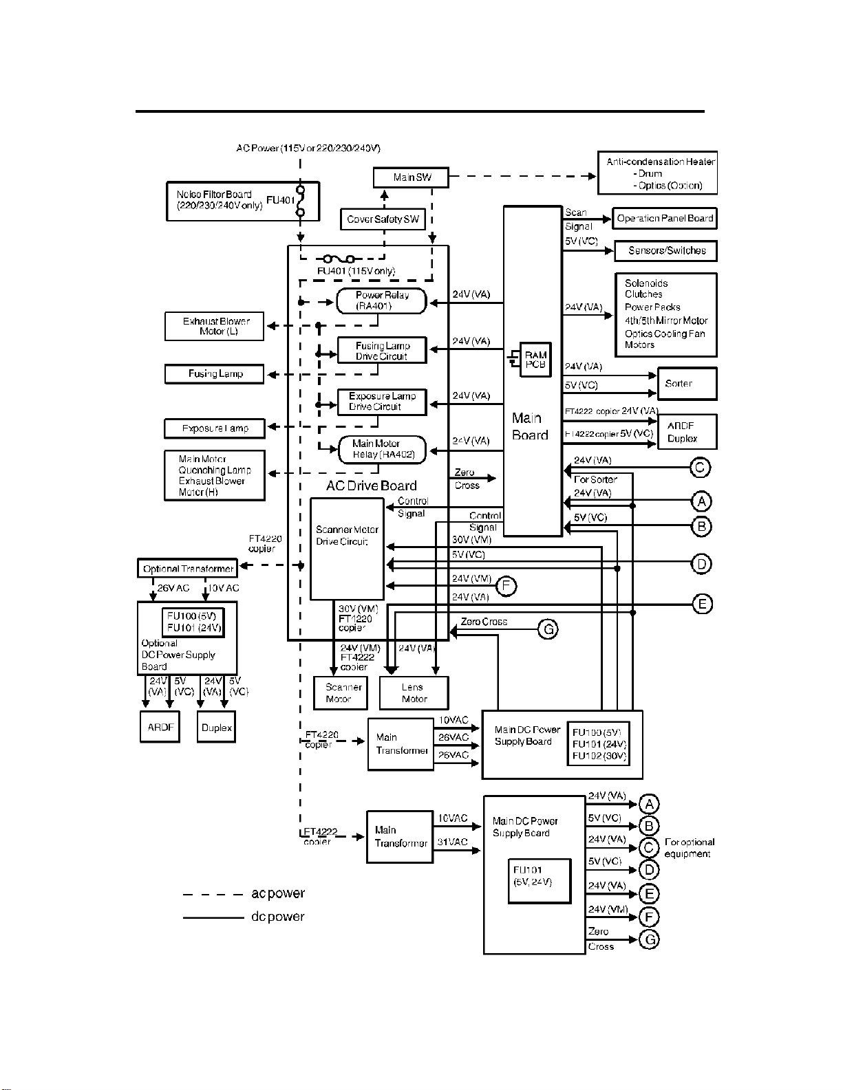
8. AC POWER AND DC POWER DISTRIBUTION
FT4220/4222 1-16 STM
Page 29

When this copier is plugged in and the main switch is turned off, ac power is
supplied via the ac drive board to the anti-condensation heater. When the
front cover and/or the exit cover is open, the cover safet y switch comp letely
cuts off power to all ac and dc components. The RAM board has a back up
power supply (dc battery) for the service program mode and misfeed job
recovery.
(FT4220)
When the main switch is turned on, the ac power supply to the
anti-condensation heater is cut off and ac power is supplied to the ac
drive board. The main and optional tra nsformers receive wall outlet ac
power through the ac drive boar d. It outpu ts 10 volts ac and 26 volts ac to
the main and optional dc power supply boards.
The main dc power supply board conver ts the 10 volts ac to +5 volts and
a zero cross signal. There are two 26 volts ac inputs. The main dc power
supply board converts them to +24 volts and +30 volts.
The +5 volt and +24 volt currents are supplied to the copier main board
and ac drive board. The +30 volt current is supplied to the ac drive board.
The zero cross signal is supplied to the copier main board thr ough the ac
drive board.
The copier main board supplies dc power to all copier dc components
except the scanner motor and lens motor. All sensors and switches
operate on +5 volts. All other dc compone nts including the power relay
(RA401) and the main motor relay (RA402) operate on +24 volts. The
copier main board also supplies the +5 volt and +24 volt currents to the
sorter.
The ac drive board supplies +30 volts to the scanner motor and +24 volts
to the lens motor. The +5 volt current is dc power for the ICs on the
scanner motor drive circuit. The main board sends the control signals to
the scanner motor and lens motor through the ac drive board.
The optional dc power supply board supplies +5 volts and +24 volts to the
duplex unit and ARDF.
STM 1-17 FT4220/4222
Page 30

(FT4222)
When the main switch is turned on, the ac power supply to the
anti-condensation heater is cut off and ac power is supplied to the ac
drive board. The main transfo rm er rece ives wall outlet ac power throu gh
the ac drive board and outputs 10 volts ac and 31 volts ac to the main dc
power supply board.
The main dc power supply board conver ts the 10 volts ac input to +5 volts
and a zero cross signal. The dc power supply board converts the 31 volts
ac to +24 volts.
The +5 volt and +24 volt currents are supplied to the copier main board,
ac drive board. The zero cross signal is supplied to the copier main board
through the ac drive board.
The copier main board supplies dc powers to all copier dc components
except the scanner motor and lens motor. All sensors and switches
operate on +5 volts. All other dc compone nts including the power relay
(RA401) and the main motor relay (RA402) operate on +24 volts.
The copier main board also supplies the +5 volt and +24 volt currents to
the sorter, ARDF and duplex unit.
The ac drive board supplies +24 volts to the scanner motor and lens
motor. The +5 volt current is dc power for the ICs on the scanner motor
drive circuit. The main board sends the control signals to the scanner
motor and lens motor through the ac drive board.
When the main board receives power, it activates the power relay (RA401 )
which then supplies ac power to the fusing lamp drive circuit, and the
exposure lamp drive circuit on the ac drive board. The exhaust blower motor
begins rotating at low speed. The fusing lamp drive circuit receives a trigger
signal from the main board and the fusing lamp lights. T he exposur e lamp
does not turn on until the main board send a trigger pulse to the exposure
lamp drive circuit.
When the Start key is pressed, the main board ener gizes the main motor
relay (RA402). Then, the main motor and the quenching lamp turn on and the
exhaust blower starts rotating at high speed.
When the main switch is turned off, power is cut off to the main board and to
RA401, and the drum and option al anticond ensat ion heaters are turned on.
The exposure lamp and the fusing lamp power lines are completely
disconnected from the line voltage .
FT4220/4222 1-18 STM
Page 31

SECTION 2
DETAILED SECTION
DESCRIPTIONS
Page 32

1. DRUM
1.1 OPC DRUM CHARACTERISTICS
An OPC has the characteristics of:
1. Being able to accept a high negative electrical charge in the dark. (The
electrical resistance of a photoconductor is high in the absence of light.)
2. Dissipating the electrical charge when expose d to light. (Exp osur e to light
greatly increases the condu ctivity of a photocond uctor .)
3. Dissipating an amount of charge in direct proportion to the intensity of the
light. That is, where stronger light is directed to the photoconductor
surface, a smaller voltage remain s on the OPC.
4. Being less sensitive to changes in temperature (when compared to
selenium F type drums) .
5. During the drum’s life, drum resid ual voltage gradua lly increases and the
photoconductive surface becomes worn. Therefore, some compensation
for these character istics is require d.
STM 2-1 FT4220/4222
Page 33

1.2 DRUM UNIT
[B]
[A]
[C]
[H]
[F]
[G]
[E]
[C]
An organic photoconductor drum [A] is used on this model.
A drum unit [B] is used to hold the drum to prevent stress on the drum. The
drum unit consists of an OPC drum, ID sensor [C] and pick-off pawls [D].
When the drum is replaced, and/or the pick-off pawls and/or the ID sensor
are cleaned, the drum unit must be rem oved fro m the copier as a unit.
The drum is driven by the main motor [E] through the main motor gear [F], a
relay gear and the drum drive gear [G]. The pick-off pawls are always in
contact with the drum surface. The ID sensor is electrically connected to the
ID sensor connector [H].
[D]
FT4220/4222 2-2 STM
Page 34

2. DRUM CHARGE
2.1 OVERVIEW
[A]
[D] [B]
[C]
[D]
[A]
This copier uses a single wire scorotron and a highly sensitive OPC drum [A].
The corona wire [B] generates a corona of negative ions when the
CC/Grid/Bias power pack [C] applies a high voltage. The CC/Grid/Bias power
pack also applies a negative high voltage to a stainless steel grid plate [D].
This insures that the drum coating rece ives a uniform negative char ge as it
rotates past the corona unit.
The exhaust blower, located above the copy exit, causes a flow of air from
the upper area of the developme nt unit through the charge corona unit. This
prevents uneven build-u p of negative ions that can ca use uneven image
density. The exhaust blower runs at half speed when in the stand- by
condition and runs at full speed while copying.
The exhaust blower has an ozone filter (active carbons) which adsor bs ozone
(O3) generat ed by the corona char ge. The ozone filter decreases in efficiency
over time as it adsorbs ozone. The ozone filter should be replaced at every
60,000 copies.
The flow of air around the charge corona wire may deposit paper dust or
toner particles on the corona wire. These particles may interfere with
charging and cause low density bands on copies. The wire cleaner cleans
the corona wire when the operator slides the corona unit in and out.
STM 2-3 FT4220/4222
Page 35

2.2 CHARGE CORONA WIRE CLEANER MECHANISM
[B]
[A]
[D]
Pads [A] above and below the charge corona wire clean the wire as the
charge unit is manually slid in and out.
The cleaner pad bracket [B] rotate s when the charge unit is fully extended
and the bracket is pulled up against the rear block [C]. This moves the pads
against the corona wire (see illustration). If the charge unit is not fully
extended, the pads do not touch the corona wire.
The pads move away from the wire when the charge unit is fully inserted and
the cleaning bracket is pushed against the front block [D].
After copier installation the key operator should be instructed how to use this
mechanism when copies have white streaks.
[C]
FT4220/4222 2-4 STM
Page 36

2.3 CHARGE CORONA CIRCUIT
VA [24]
VC [5]
CC Trig [▼24 ]
Grid Trig (PWM) [▲0→0/5]
Not Used
GND [0]
CN112-8
CN112-7
CN112-6
CN112-5
CN112-4
CN112-3
CN112-2
CN112-1
CN1-1
CN1-2
CN1-3
CN1-4
CN1-5
CN1-6
CN1-7
CN1-8
CC/Grid/Bias
Power Pack
(P1)
M
Charge
Corona Wire
G
Grid
Development
B
Roller
Main Board (PCB 1)
The main board supplies +24 volts to the CC/Grid/Bias power pack at CN1-1
as the power supply source. After the Start key is pressed, the CPU drops
CN1-3 from +24 volts to 0 volts. This energizes the charge corona circuit
within the CC/Grid/Bias power pack, which applies a high negative voltage of
approximately –5.6 kv to the charge coro na wire. The corona wire then
generates a negative corona charge.
The grid limits the charge voltage to ensure that the charge does not fluctuate
and an even charge is applied to the drum surfa ce.
The grid trigger pulse applied to CN1-5 is a pulse width modulated signal
(PWM signal). This signal is not only a trigger signal; it also changes the
voltage level of the grid. As the width of the pulse applied increases, the
voltage of the grid also increases.
STM 2-5 FT4220/4222
Page 37

2.4 GRID VOLTAGE CORRECTION
To maintain good copy quality over the drum ’s life, the grid voltage is
changed by the following:
• Drum residual voltage correction (Vr correction)
• Vp correction
2.4.1 Drum Residual Voltage Correction (Vr correction)
During the drum’s life, the drum may fatigue electrically and residual voltage
(Vr) on the drum may gradually incre ase. When this happens, the corona
charged voltage on the drum is not discharged enough in the quenching and
exposure processes. Even if the developme nt bias is applied in the
development process, the background area of the original on the drum may
attract some toner. This may cause dirty background on copies. The Vr
correction prevents this phenomenon as follows:
A pattern (Vr patter n) is developed on the drum every 1000 copie s and its
reflectivity is detected by the ID sensor to measure the residual voltage. This
is called residual voltage detection. If the reflectivity is low, the residual
voltage will be high.) When the Vr pattern is developed, all blocks of the
erase lamp turn on, the grid voltage is –500 volts and the development bias
voltage is 0 volt. (See page 2-8 for standard image density grid voltage.)
The CPU determines what level of Vr correction is necessary depending on
the output (Vr ratio [L]) from the ID sensor.
Vrp
L =
x 100(%)
Vsg
Vrp: ID sensor output for Vr pattern
Vsg: ID sensor output for bare drum
The current Vr ratio is displayed by SP67.
The CPU increases the development bias voltage depe nding on the Vr ratio
to prevent dirty background on copies. (See page 2-33 for more information.)
The CPU also increases the grid voltage to ensure proper image density
depending on the Vr ratio. (See page 2-8.)
FT4220/4222 2-6 STM
Page 38

2.4.2 Vp Correction
Due to the OPC drum’s characteristics, the chargeability of the
photoconductor may decrease until around 2,000 copies after installation. It
will stay stable after 2,000 copies. This characteristic especially affects
developing of the ID sensor pattern. The ID sensor pattern developed on the
drum becomes lighter after 2,000 copies causing higher toner concentration
in the developer. Vp correct ion is made to prevent this phenomenon and
functions as follows:
The CPU keeps track of the total number of copies made with the drum. The
grid voltage for the toner density dete ction incre ases by –20 volts after 2,000
copies (see page 2-8). The drum counter is displayed by SP69. The counter
must be reset by SP66 when the drum is replaced with a new one.
STM 2-7 FT4220/4222
Page 39

2.5 GRID VOLTAGE CONTROL
The main board controls the grid voltage for a copy image and the toner
density detection through the CC/Grid/Bias power pack. As the grid voltage
for the image density control becomes less, the copy image becomes lighter
and vice versa.
As the grid voltage for the toner density dete ction becom es less, th e toner
concentration in the developer becomes higher and vice versa.
The grid voltage is based on the standard grid voltage and the correction
factor as follows:
2.5.1 Image Density Control
Grid Voltage = Standard image density grid voltage (–920 volts [SP60 = 5])
+
Vr correction factor
Vr Correction Factor
L Change of grid voltage
100 to 89 (%)
88 to 76 (%)
75 to 62 (%)
61 to 45 (%)
44 to 0 (%)
±0 (volt)
–40 (volts)
–80 (volts)
–120 (volts)
–160 (volts)
L = Vrp/Vsg x 100 (Vr correction ratio)
Vrp: ID sensor output for Vr correction pattern
Vsg: ID sensor output for bare drum
NOTE: The grid voltage for between copies (non-image area) is 0 volt
(Fixed).
2.5.2 Toner Density Detection
Grid Voltage = Standard ID sensor grid voltage (–560 volts [SP62 = 5])
+
Vp correction factor
Drum counter Vp correction factor
0 to 1,999 (copies)
Over 2,000 (copies)
±0 (volt)
–20 (volts)
2.5.3 Vr Detection
Grid Voltage = –500 volts (Fixed)
FT4220/4222 2-8 STM
Page 40

3. OPTICS
[G]
[H]
3.1 OVERVIEW
[C] [B] [A] [F]
[D] [J]
During the copy cycle, an image of the original is reflected onto the drum
surface through the optics assem bly as follows.
Light Path:
Exposure Lamp [A] → Original → Fir st Mirror [B] → Second Mirror [C]
→ Third Mirror [D] → Green Color Filter [E] → Lens [F] → Fourth Mirror [G]
→ Fifth Mirror [H] → Sixth Mirror [I] → Drum [J]
[I]
[K][E]
The two optics cooling fans [K] draw cool air into the optics cavity. The air
flows from the right to the left in the optics cavity and exhausts through the
vents in the left cover. These fans operate during the copy cycle.
This copier has six standard reproduction ratios: Three redu ction rat ios, two
enlargement ratios, and full size. It also has a zoom function . The oper ator
can change the reproduction ratio in one percent steps from 50% to 200%.
Stepper motors are used to change the positions of the lens and mirrors.
Separate motors are used because the wide range of reproduction ratios
makes it mechanically difficult for one motor to position both the lens and
mirrors. A stepper motor is also used to drive the scanner. This motor
changes the scanner speed according to the reproduction ratio.
The thermoswitch opens at 140°C and removes ac power to the exposure
lamp to prevent overheat ing. The therm oswitch can be reset man ually when
the exposure lamp area cools.
A green color filter [E] is located just in front of the lens to enable the OPC to
more effectively reproduce red image areas.
STM 2-9 FT4220/4222
Page 41

3.2 SCANNER DRIVE
[D]
[E]
[A]
[G]
3.2.1 1st and 2nd Scanner Drive Mechanism
This model uses a stepping motor [A] to drive the scanners. Bo th ends of
each scanner are driven to prevent skewing. The scanners have sliders [B],
which ride on guide rails.
The scanner home position is detected by the home position sensor [C]. The
scanner return positio n is determined by counting the scanner motor drive
pulses.
[B]
[F]
[C]
The first scanner [D], which consists of the exposure lamp and the first mirro r,
is connected to the scanner drive wire by the wire clamps [E]. The second
scanner [F], which consists of the second and third mirr ors, is connecte d to
the scanner drive wire by movable pulleys (the second scanne r pulley [G]) .
The pulley moves the second scanner at half the velocity of the first scanner.
This is to maintain the focal distance between the original and the lens durin g
scanning. This relationship can be expressed as:
V1r = 2 (V2r) = VD/r
where r = Reproduction ratio
V1r = First scanner velocity (when the reproduction ratio
is "r")
V2r = Second scanner velocity (when the reproductio n ratio
is "r")
VD = Drum peripheral velocity (120 mm/s)
FT4220/4222 2-10 STM
Page 42

3.3 LENS DRIVE
: Reduction
: Enlargement
[D]
[C]
[E]
[B]
[G]
[A]
3.3.1 Lens Drive
The lens motor [A] (stepper mot or) changes the lens [B] position thro ugh the
lens drive wire [C] in accordance with the selected reprodu ction rat io to
provide the proper optical distance between the lens and the drum surface.
The rotation of the lens drive pulley moves the lens back and forth in discrete
steps. The home position of the lens is detected by the home position sensor
[D]. The main board keeps track of the lens position based on the number of
pulses sent to the lens motor.
3.3.2 Shading Mechanism
The shading plates [E] are installed on the lens housing [F] and are slid open
and shut by the groove cams [G]. When the lens moves in the reduction
direction, the groove cams move the shading plates closer together. The
plate blocks part of the light passing through the lens to keep the intensity of
the light on the drum even.
[F]
STM 2-11 FT4220/4222
Page 43

3.3.3 Lens Positioning
[D]
Reduction Side
[A]
[C]
Home Position (100%)
(100% → 141/155%)
[B]
(141/155% → 71/65%)
(71/65% → 93%)
(93% → 71/65%)
(71/65% → 141/155%)
(141/155% → 122/129%)
(122/129% → 141/155%)
(141/155% → 100%)
(100% → 71/65%)
(71/65% → 100%)
Enlargement Side
The lens home position sensor [A] informs the main board when the lens is at
full size position (home position). The main board determ ines the lens stop
position in reduction and enlargement modes by counting the number of
steps the motor makes with refere nce to th e lens home position . When a new
reproduction ratio is selected, the lens [B] moves directly to the selected
magnification position.
The lens home position is registered each time the lens starts from or passes
through the lens home position sensor. As the lens moves from the
enlargement side to the reduction side, the sensor registers the home
position. This occurs when the actuator plate [C] enters the lens home
position sensor.
A small vibration can be observed when the lens moves through home
position from the reduction side to the enlargem ent side because the lens is
going in the wrong direction to register the home position. The lens
overshoots the home position by only one pulse before going back to register
the home position.
The lens always stops while moving from left to right (as viewed from the
front) to minimize the err or caused by mechanical play in the drive gears [D].
FT4220/4222 2-12 STM
Page 44

3.4 4TH AND 5TH MIRROR DRIVE
(100% → 71/65%)
[B]
[A]
Home Position (100%)
(100% → 141/155%)
(141/155% → 71/65%)
(71/65% → 93%)
(93% → 71/65%)
(71/65% → 141/155%)
(141/155% → 122/129%)
(122/129% → 100%)
(71/65% → 100%)
3.4.1 Drive
The 4th/5th mirro r drive motor (stepper motor ) chang es th e 4th/5t h mirr or
assembly position through the pinion gears [A] and the rack gear [B] in
accordance with the selected repr oduct ion ratio to provide the proper optical
distance between the lens and drum surface.
3.4.2 Positioning
The positioning mechanism is similar to that of lens positioning, as shown in
the above positioning chart. The scanner always stops while moving fro m
right to left (as viewed from the front).
STM 2-13 FT4220/4222
Page 45

3.5 ORIGINAL SIZE DETECTION IN PLATEN MODE
[C]
(FT4222 Copier Only)
[E]
[B]
[G]
[D]
[A]
[F]
An original width sensor [A] and an original length sensor [B] are under the
exposure glass [C]. The original width sensor consist s of two reflective
photosensors. The original lengt h sen sor consists of four reflective
photosensors (five for european version).
These sensors are used for the original size detection.
When the main switch is on, these sensors are active and the original size
data is always sent to the main CPU. The CPU checks the data twice in
platen mode for determining the original size for APS or ARE modes.
The first check is done when the platen cover position sensor [D] or DF
position sensor [E] is actuated. At this time the platen cover (or DF) is
lowered to about 10 cm (4") above the exposure glass. Only the sensors
underneath the original receive the reflected light and output a low signal.
The other sensors output a high signal.
The second check is done when the platen cover (or DF) is closed and the
platen cover closed switch [F] is actuated. The platen cover closed switch is
a lead switch. A magnet [G] mounted on the platen cover (or DF) actuates
the lead switch.
FT4220/4222 2-14 STM
Page 46

The CPU compares the second check with the first one to judge if the original
S16-1
is present above the sensor or not according to the following table.
First
data
High High Original exists
High Low No original
Low High
Low Low Original exists
Second
data
Judgement
Displays "Check Paper
Size" indicator
Original
Width
Sensors
S15-2
S15-1
Original Length Sensors
S16-2
S16-4
S16-5
The CPU finally determines the original size from the above judgements. The
following table shows how the original size is determined with information of
each sensor.
Sensors
Original Size
A3 11" x 17" 0 0 0 0 - 0 0
B4
—
F4 — 1000-11
A4 lengthwise 8
B5 lengthwise 8" x 10" 1 0 0 1 - 1 1
A5 lengthwise
or smaller
A4 sideways 11" x 8
B5 sideways 8
A5 sideways 1 0 1 1 - 1 1
11" x 15"
10" x 14"
81/2" x 14"1000-01
1/2" x 11"1000-11
5
1/2" x 81/2" or
smaller
1/2"0001-11
1/2" x 51/2" 0011-11
Original Width
Sensor
S15-1 S15-2 S16-1 S16-2 S16-3 S16-4 S16-5
0000-01
1111-11
0: Original exists 1: No original
Original Length Sensor
NOTE: 1. The inch version machine does not have S16-3.
2. When the original size is A5 lengthwise/51/2" x 81/2" or smaller, the
machine cannot detect the original size.
When a copy is made with the platen cover (DF) open, the CPU uses the
original size data detected when the Start key is pressed.
When an original is fed to the exposure glass through the DF, the CPU uses
the original size data from the DF.
STM 2-15 FT4220/4222
Page 47

3.6 AUTOMATIC IMAGE DENSITY SENSING
70 mm
B
Sampled area
A
[A]
[C]
[B]
Light from the exposure lamp is reflect ed from the original and travels to the
lens [A] via the mirrors. The auto ID sensor [B], a photodiode, is mounted on
the upper front frame. The sensor cover [C] has a hole in it to allow light to
fall directly onto the sensor. Sampling starts 10 millimeters from the leading
edge of the original and continues to 50 millimeters from the leading edge of
original in full size mode. The length of "A" and "B" will vary depending on the
selected reproduction ratio.
The lengths "A" and "B" in each reproduction ratio are calculated as follows:
A =
Reproduction Ratio (%)
The photosensor circuit converts the light intensity to a voltage. The detected
10 mm
x 100 B =
Reproduction Ratio (%)
50 mm
x 100
voltage is amplified and sent to the main PCB. The CPU stores the voltage of
each sampled point in RAM. It then computes the image density of the
original from the maximum sample voltage and changes the development
bias accordingly. (See page 2-31 for deta ils.) The exposure lamp voltage is
constant regardle ss of the image density of the origina l.
FT4220/4222 2-16 STM
Page 48

3.7 EXPOSURE LAMP VOLTAGE CORRECTION
To maintain good copy quality, the exposure lamp voltage is changed by the
following:
• VL correction
• Drum wear correction
• Reproduction ratio correction
3.7.1 VL Correction
The light intensity may decrease because of dust accumulated on the optics
parts. This may cause dirty backgrounds on copies. To compensate for this
phenomenon, VL correction is done as follows:
The CPU keeps track of the amount of time that the main switch is on. The
exposure lamp voltage increa ses at set intervals, which ca n be changed by
SP61 (see page 2-20).
3.7.2 Drum Wear Correction
During the drum’s life, the photoconductive surface of the drum becomes
worn by contact with the cleaning brush. This affects the drop of the drum
photosensitivity. This may cause dirty backgrounds on copies.
To compensate for this phenomenon, drum wear correction is made as
follows:
The CPU keeps track of the drum rotation time. The exposu re lamp voltage
increases at set intervals (see page 2-21).
3.7.3 Reproduction Ratio Correction
To compensate for the change in the concentration of light on the drum, the
exposure lamp voltage increases depending on the selected reproduction
ratio (see page 2-21).
STM 2-17 FT4220/4222
Page 49

3.8 EXPOSURE LAMP VOLTAGE CONTROL
The main board controls the exposu re lamp voltage through the ac drive
board. The exposure lamp voltage is based on the base lamp voltage and
various correction factors. The exposure lamp data setting determines the
base lamp voltage. The following table gives the approximate lamp voltage
for each data setting.
Exposure Lamp Data/Voltage Reference Table (SP48)
Exposure lamp voltage
Exposure
lamp data
machine
100 57.1 105.9 126 71.9 133.4
101 57.6 106.9 127 72.5 134.5
102 58.2 108.0 128 73.0 135.5
103 58.8 109.1 129 73.6 136.6
104 59.3 110.1 130 74.2 137.6
105 59.9 111.2 131 74.7 138.7
106 60.5 112.2 132 75.3 139.8
107 61.1 113.3 133 75.9 140.8
108 61.6 114.4 134 76.5 141.9
109 62.2 115.4 135 77.0 142.9
110 62.8 116.5 136 77.6 144.0
111 63.3 117.5 137 78.2 145.1
112 63.9 118.6 138 78.7 146.1
113 64.5 119.6 139 79.3 147.2
114 65.0 120.7 140 79.9 148.2
115 65.6 121.8 141 80.5 149.3
116 66.2 122.8 142 81.0 150.4
117 66.8 123.9 143 81.6 151.4
118 67.3 124.9 144 82.2 152.5
119 67.9 126.0 145 82.7 153.5
120 68.5 127.1 146 83.3 154.6
121 69.0 128.1 147 83.9 155.6
122 69.6 129.2 148 84.4 156.7
123 70.2 130.2 149 85.0 157.8
124 70.8 131.3 150 85.6 158.8
125 71.3 132.4
115V
(standard)
220/230/240V
machine
Exposure
lamp data
Exposure lamp voltage
(standard)
115V
machine
NOTE: Exposure lamp rating: 115 V machine: 97 V/280 W
220/230/240 V machine: 180 V/310 W
220/230/240V
machine
Default data value: 126
FT4220/4222 2-18 STM
Page 50

The method of control is different depending on whether the image density is
manually selected or the auto image density mode is selected.
The exposure lamp voltage consists of the following factors:
Exposure lamp voltage = Base exposure lamp voltage factor
(Manual or auto ima ge density mod e)
+
VL correction factor
+
Drum wear correction factor
+
Reproduction ratio correction factor
3.8.1 Base Lamp Voltage Factor in Manua l Imag e Densi ty Mo de
Manual ID level 1234567
Exposure lamp data Vo –4 Vo Vo Vo Vo +4 Vo +8 V o +12
Darker Lighter
The above table shows changes in the exposure lamp data in manual image
density mode.
SP48 sets the exposure lamp data for level 4 (Vo) of manual image density
mode. A value from 100 to 150 can be selected.
3.8.2 Base Lamp Voltage Facto r in Aut o Ima ge Dens ity Mode
In auto ID mode, the CPU selects the level 4 (Vo) exposure lamp data
regardless of the input from the auto image density sensor. When the auto
image density level is set to lighter in SP34, the exposure lamp data changes
to that of manual ID level 5 as shown below. When the auto image density
level is set to darker, the development bias shifts +40 volts. Only the
development bias varies according to the input from the auto image density
sensor. (See page 2-31.)
Auto Image Density Level (SP34)
Auto image density level SP data (SP34) Exposure lamp data Development bias shift
Normal 0
Darker 1
Lighter 2
STM 2-19 FT4220/4222
Same as level 4
(Vo ±0)
Same as level 4
(Vo ±0)
Same as level 5
(Vo +4)
±0 volts
+40 volts
±0 volts
Page 51

3.8.3 VL Correction Factor
SP data (SP61) Change of exposur e lamp data /Ma chine on time
0 +1/70H
1 +1/140H
2 +1/40H
3 +1/20H
4 +1/10H
5 +1/5H
6 No Correction
(Factory Setting: SP61 = 0)
The exposure lamp data increases by +1 at set intervals of the machine on
time. This interval can be changed by SP61 as shown in the above table.
The total increase for VL correction cannot exceed +20. When cleaning the
optics parts, SP94 should be performed to clear VL correction.
VL correction clear (S P94)
SP data (SP94) VL correction
0 Not clear
1 Clear
NOTE: When "1" is input in SP94, the machine on time (SP57) data is
cleared. Perform SP94 whenever optics parts are cleaned.
FT4220/4222 2-20 STM
Page 52

3.8.4 Drum Wear Correction Factor
Drum rotation time (SP58) Change of exposure lamp data
0 to 24 H ±0
25 to 49 H +1
50 to 74 H +2
75 to 99 H +3
More than 99 H +4
To compensate for OPC dru m wear caused by contact with the cleanin g
brush, the exposure lamp data increases at set interval of drum rotation time
as shown in the above table.
The drum rotation time is displayed by SP58. This time must be reset by
SP66 when the drum is replaced with a new one.
3.8.5 Reproduction Ratio Correction Factor
Reproduction rat io Change of exposure lamp data
50 to 61% +2
62 to 139% ±0
140 to 159% +2
160 to 179% +6
180 to 200% +10
The exposure lamp data increases depending on the selected reproduction
ratio as shown in the above table.
STM 2-21 FT4220/4222
Page 53

3.9 EXPOSURE LAMP CONTROL CIRCUIT
Main Board (PCB1)
Zero Cross
TP105
(LAMP)
E
Feed back
signal
CPU
+24V
C
24V
0V
Trigger Pulse
B
CN435-1
CN122-8
CN122-5
To dc power
supply board
CN122-4
CN122-7
CN435-4
CN437-4
CN435-5
CN435-2
AC power
Zero cross
Trigger pulse
Lamp power
A
B
C
D
To dc power
supply board
CN437-6
VR401
R403
R401
AC Drive Board (PCB2)
ZD
401ZD402
R404
ZD
403ZD404
R411
D401
R406
TRC401
R413
R404
C401
PC401
DB401
CR401
L401
L402
TR401
C411
T402
CN419-1
Thermo-SW
(TS)
Exposure
Lamp
(L1)
D
CN419-2
T407
A
AC115V
/220V
/230V
/240V
Feedback
signal
E
Feedback
The main board sends lamp trigger pulses to the ac drive board from
CN122-7. PC401 activates TRC401, which provides ac power to the
exposure lamp, at the trailing edge of each trigger pulse.
The voltage applied to the exposure lamp is also provided to the feedback
circuit. The feedback circuit steps down (TR401), rectifies (DB401), and
smoothes (zener diode s and capacitors) the lamp voltage. The CPU monitor s
the lowest point of the smoothed wave (feedba ck signal), which is dire ctly
proportional to the actual lamp voltage.
The CPU changes the timing of the trigger pulses in response to the
feedback voltage. If the lamp voltage is too low, the CPU sends the trigger
pulses earlier so that more ac power is applied to the exposure lamp . This
feedback control is performed instantly; so, the lamp voltage is always stable
even under fluctuating ac power condit ions.
The voltage applied to the exposure lamp can be changed with SP48 (Light
Intensity Adjustment). The ADS voltage adjustment (SP56) must be done
whenever the light intensity adjustm ent is done.
FT4220/4222 2-22 STM
Page 54

4. ERASE
Lo
Lc
4.1 OVERVIEW
[A]
LE
EL
[B]
SE
ES
LE: Lead edge erase margin 2.5 ±1.5 mm
SE: Side erase margin 2.0 ±2.0 mm on each side;
total of both sides 4 mm or less
LO: Original width
LC: Charged width of drum
EL: Lead edge erase
ES: Side erase
The erase lamp [A] consists of a line of LEDs (43 LEDs) extending across the
full width of the drum [B].
The erase lamp has four functions: lead edge erase, side erase, trail edge
erase and editing mode erase (erase edge or/and erase center ). Trail edge
erase begins after the trailing edge of the copy paper; therefore, the trailing
edge of the copy will not be erased.
STM 2-23 FT4220/4222
Page 55

Front
Rear
4.1.1 Lead Edge Erase
The entire line of LEDs turns on when the main motor turns o n. They stay on
until the erase margin slightly overlaps the lead edge of the original image
area on the drum (Lead Edge Erase Margin). This prevents the toner density
sensor pattern from being developed every copy cycle and the shadow of the
original edge from being develo ped on the paper. At this point, side erase
starts. The width of the lead edge erase marg in can be adjusted using SP41.
During the toner density detection cycle (once every ten copy cycles), a block
of erase lamps (labeled "o" above) turns off long enough for the sensor
pattern to be developed.
The entire line of LEDs turns on when the residual voltage on the OPC drum
is being detected (Vr detection).
4.1.2 Side Erase
Based on the combination of copy paper size and the reproduction ratio data,
the LEDs turn on in blocks (labeled "a" – "p" above). This reduces toner
consumption and drum cleaning load.
FT4220/4222 2-24 STM
Page 56

The following table shows which blocks of erase lamp LEDs turn on
depending on the paper size and the repro duction ratio:
Blocks ON Paper size Reproduction ratio (%)
None
a 95–98
a–b 91–94
a–c B4, B5 Sideways 87–90
a–d 83–86
a–e 79–82
a–f 8
a–g A4 Lengthwise 70–73
a–h 67–69
a–i 64–66
a–j 61–63
a–k 57–60
a–l 54–56
a–m 52–53
a–n A5 Lengthwise, 5
All (a–p) Lead Edge and Trail Edge Erase/For Vr Detection Cycles
a–n, p For Toner Density Detection Cycles
A3, A4 Sideways, 11" x 17",
11" x 8
1/2", Manual Feed
1/2" x 11", 81/2" x 51/2", F4 74–78
1/2" x 81/2" 50–51
99–200
4.1.3 Trail Edge Erase
The entire line of LEDs turns on after the trailing edge of the latent image has
passed. Therefor e, a trailing erase mar gin cannot be observed on the copy.
The LEDs stay on to erase the leading edge of the latent image in the next
copy cycle. After the final copy, the erase lamps turn off at the same time as
the main motor.
4.1.4 Editing Mode Erase
When copying a thick book original, the binding margin at the center and the
edges may appear dirty on copies. To prevent this, the erase center mode,
erase edge mode, or erase cente r and edge mod e can be selected as follows:
1. Press the Program key.
2. Press one of the following numbers:
Erase center..................... Press "6"
Erase edge....................... Press "7"
Erase center and edge..... Press "8"
a) Center Erase
The erase margin of the center is done through the timing of when the entire
line of LEDs turns on. The margin can be changed by SP26 as shown.
STM 2-25 FT4220/4222
Page 57

SP data (SP26) Margin of the center
0 20 mm
1 10 mm
b) Lead and Trail Edge Erase
The erase margin of the lead and
2 15 mm
3 25 mm
(Factory setting: SP26 = 0)
trail edges is done through the
timing of when the entire line of
LEDs turns on. The margin can be changed by SP18 as shown.
Margin of the lead and
trail edges
c) Si d e Edge Erase
The erase margin of the side
edges is done through which
blocks of the LEDs turn on. The
SP data (SP18)
0 10 mm
1 5 mm
2 15 mm
3 20 mm
(Factory setting: SP18 = 0)
margin can be changed by SP13.
The margin of the side edges
depends on the paper size and reproduction ratio.
The right table show the margin of the side edges for the various paper sizes
in the full size copy mode.
Paper Size
A3, A4,
11" x 17", 11" x 8.5",
11" x 15"
B4, B5, 10" x 14" 13.5 mm 7.5 mm
8.5" x 14", 8.5" x 13",
8.5" x 11", 8.5" x 5.5"
A4R, A5, 8" x 13",
8" x 10.5", 8" x 10"
B5R, B6 10 mm 5 mm
*
(Factory setting: SP13 = 0)
Margin of side edges
SP13 = 0 SP13 = 1
13 mm 5.5 mm
11 mm 3.5 mm
12 mm 6 mm
11 mm 6 mm
* Non-standard paper size
FT4220/4222 2-26 STM
Page 58

5. DEVELOPMENT
5.1 OVERVIEW
When the main motor turns on and the development clutch solenoid is
de-energized , the paddle roller [A] development rolle r [B] the auger [C], and
the agitator [D] start turnin g. The padd le roller picks up developer in its
paddles and transports it to the development roller. Internal permanent
magnets in the development roller attract the developer to the developme nt
roller sleeve.
[B]
[E]
[A] [D]
[F][C]
The turning sleeve of the development roller then carries the developer past
the doctor blade [E]. The doctor blade trim s the developer to the desired
thickness and creates backspill to the cross-mixing mechanism .
The development rolle r continues to turn, carrying the developer to the OPC
drum. When the developer brush contact s the drum surf ace, the negatively
charged areas of the drum surface attract and hold the positively charged
toner. In this way, the latent image is developed.
The development rolle r is given a negative bias to prevent toner from being
attracted to non-im age areas on the drum that may have residual negative
charge. The bias also controls image density.
After turning about 100 degrees more, the development roller releases the
developer to the developer tank. The developer is agitated by the paddle
roller, agitator [D], and the cross-mixing mechanism.
Rotation of the paddle roller and development roller tend to cause air
pressure inside the unit to become higher than the air pressure around the
development unit. A hole, fitted with a filter [F], has been added to the top of
the unit to relieve air pressure and to minimize toner scattering.
STM 2-27 FT4220/4222
Page 59

5.2 DRIVE MECHANISM
[E]
[I]
[G]
[H]
[J]
[A]
[D]
When the main motor turns, the rot ation is transm itte d from the developm ent
drive gear [A] to the development roller gear [B] through the development
clutch [C]. (The rotation is transmitted to the development drive gear when
the development solenoid [D] is de-ene rgize d.) Then, the rot ation is
transmitted from the development roller gear to the paddle roller gear [E]
through the idle gear [F].
A gear [G] on the front end of the paddle roller shaft drives the auger gear [H]
and the agitator gear [I]. The paddle roller shaft has a knob [J] on the front
end so that it can be turned manually to exchange developer. The knob has a
one-way clutch inside. The one-way clutch pre vents the develo pme nt roller
from turning in the wrong direction.
[B]
[F]
[C]
The development clutch solenoid energizes each copy cycle after image
development is completed. This stops the rollers, thereby reducing developer
fatigue.
FT4220/4222 2-28 STM
Page 60

5.3 CROSS-MIXING
[A]
[B]
[F]
[D]
[E]
This copier uses a standard cross-mixing mechanism to keep the toner and
developer evenly mixed. It also helps agitate the developer to prevent
developer clumps from forming and helps create the triboelectric charge.
The developer on the turning development roller is split into two parts by the
doctor blade [A]. The part that stays on the development roller [B] forms the
magnetic brush and develops the laten t image on t he drum. The par t th at is
trimmed off by the doctor blade goes to the backspill plate [C].
As the developer slides down the backspill plate to the agitator [D], the mixing
vanes [E] move it slightly toward the rear of the unit. Part of the developer
falls into the auger inlet and is transported to the front of the unit by the auger
[F].
The agitator moves the developer slightly to the front as it turns, so the
developer stays level in the development unit.
[C]
STM 2-29 FT4220/4222
Page 61

5.4 DEVELOPMENT BIAS FOR IMAGE DENSITY CONTROL
Image density is controlled by changing two items: (1) the strength of the bias
voltage applied to the developmen t roller sleeve, and (2) the strength of the
voltage applied to the exposure lamp.
Applying a bias voltage to the development sleeve reduces the potential
between the development roller and the drum, thereby reducing the amount
of toner transferr ed. As the bias voltage becomes greater, the copy image
becomes lighter. Similarly, increasing the voltage to the exposure lamp
causes an increase in light intensity which also results in lighter copies.
The method of control is different depending on whether the image density is
manually selected or the automatic ID mode is used.
The development bias applied to the developme nt roller sleeve has the
following three factors:
Development bias voltage = Base bias voltage factor
(Manual or automatic image density control)
+
Base bias voltage adjustment facto r
+
Vr correction factor
The base bias voltage for non-image areas (between copies) is –200 volts.
The above correction factors are also applied .
5.4.1 Base Bias Voltage Factor in Manual Image Density Control
Darker Lighter
Manual ID level 1 2 34567
Base bias voltage –120 –120 –160 –200 –200 –240 –280
Exposure lamp data Vo –4 Vo Vo Vo Vo +4 Vo+8 Vo+12
In manual ID control mode, the base bias voltage depends on the manually
selected ID level. The voltage applied at each ID level is shown in the above
table. The base exposure lamp voltage also varies depending on the manual
ID level as shown in the table. (See page 2-19 for more information.)
FT4220/4222 2-30 STM
Page 62

5.4.2 Base Bias Voltage Factor in Automatic Image Density Control
In automatic image density control mode, the base exposure lamp voltage is
fixed to Vo. (See page 2-19 for more informa tion. ) Imag e density is contr olled
by changing only the base bias voltage.
The base bias voltage depends on the backgroun d image densit y of the
original, which is measured using the auto ID sensor. (See page 2-16 for
more information.)
The CPU checks the voltage output from the automat ic ID circuit. This circuit
has a peak hold function. The peak hold voltage corresponds to the
maximum reflectivity of the orig inal. The CPU then deter mine s the proper
base bias level with reference to the peak hold voltage.
The following table gives the base bias voltages at each ADS output level.
When the automatic density level is set to darker by SP34, the base bias
voltage shifts +40 volts as shown in the following table.
K
Base bias voltage
Normal or lighter (S P34 = 0 or 2) Darker (SP34 = 1)
K ≥ TL1 –200 volts –160 volts
TL1 > K ≥ TL2 –240 volts –200 volts
TL2 > K ≥ TL3 –280 volts –240 volts
TL3 > K ≥ TL4 –320 volts –280 volts
TL4 > K ≥ TL5 –360 volts –320 volts
TL5 > K –380 volts –340 volts
K =
ADS Output Voltage (Peak Hold Voltage)
ADS Reference Voltage (SP56)
TL1 to TL5: Threshold level (see the following table)
STM 2-31 FT4220/4222
Page 63

To maintain the correct imag e density, the lamp data is incremented when
the reproduction ratio is changed or drum wear correction or VL correction is
done. This increment in the lamp data incre ases the intensit y of light reflected
from the original. Therefore, the auto ID sensor output voltage also changes.
In order to maintain a constant voltage for the same original when the lamp
data is incremented, the threshold levels are shifted with each increment in
the lamp data as shown in the following table.
❋ Increase of lamp data
+0 +1 +2 +3 +4 +5 +6 +7 +8 +9 +10 +11 +12
❋
TL1 0.80 0.82 0.86 0.89 0.91 0.93 0.95 0.99 1.01 1.04 1.05 1.07 1.10
TL2 0.75 0.77 0.81 0.83 0.86 0.88 0.90 0.92 0.95 0.97 1.00 1.02 1.04
TL3 0.70 0.72 0.75 0.76 0.79 0.81 0.83 0.84 0.88 0.90 0.93 0.95 0.97
TL4 0.60 0.62 0.64 0.66 0.69 0.70 0.72 0.74 0.76 0.77 0.80 0.81 0.83
TL5 0.29 0.29 0.30 0.31 0.33 0.33 0.34 0.35 0.36 0.36 0.37 0.38 0.37
+13 +14 +15 +16 +17 +18 +19 +20 +21 +22 +23 +24
❋
TL1 1.11 1.11 1.11 1.12 1.13 1.13 1.13 1.13 1.13 1.13 1.13 1.13
TL2 1.05 1.06 1.07 1.08 1.10 1.11 1.13 1.13 1.13 1.13 1.13 1.13
TL3 0.98 0.99 1.02 1.05 1.07 1.09 1.12 1.13 1.13 1.13 1.13 1.13
TL4 0.85 0.86 0.86 0.88 0.91 0.93 0.95 0.98 0.99 1.02 1.05 1.08
TL5 0.38 0.39 0.42 0.43 0.44 0.45 0.46 0.47 0.48 0.49 0.51 0.52
5.4.3 Base Bias Voltage Adjustment Factor
Base Bias Adjustment
(Black toner: SP37, Color Toner: SP79)
Image density SP data (SP37 or 79) Change of base bias voltage
Normal 0 ±0 volts
Darkest 1 +40 volts
Darker 2 +20 volts
Lighter 3 –20 volts
Lightest 4 –40 volts
The base bias voltage can be changed in SP37 for black toner or SP79 for
color toner to adjust the image density level. The above table gives the base
bias voltage for each SP mode setting. This adjustment should be done only
when the exposure lamp voltage adjustm ent (SP48) fails to achieve the
desired image density.
FT4220/4222 2-32 STM
Page 64

5.4.4 Vr Correction Factor
As the OPC drum is used, drum residual voltage (Vr) gradually incre ases. Vr
correction compen sates for residual voltage on the drum. Vr correction is
done every 1,000 copies based on the data of the drum counter (SP69) and
the Vr correction ratio (L) (SP67). The following chart shows how the bias
voltage changes depending on the Vr correction ratio (L).
Vr Correction Factor
L Change of bias voltage
100 to 89 (%)
88 to 76 (%)
75 to 62 (%)
61 to 45 (%)
44 to 0 (%)
±0 (volts)
–40 (volts)
–80 (volts)
–120 (volts)
–160 (volts)
NOTE: L = Vrp/Vsg x 100 (Vr correction ratio)
Vrp: ID sensor output for Vr correction pattern
Vsg: ID sensor output for bare drum
When the Vr correction is made every 1,000 copies, all blocks of erase lamps
turn on and the development bias becomes 0 volt to develop the Vr
correction pattern.
STM 2-33 FT4220/4222
Page 65

5.5 DEVELOPMENT BIAS CIRCUIT
VA [24]
VC [5]
Bias Trig (PWM) [▲0→0/5]
Bias FB
GND [0]
CN112-8
CN112-7
CN112-6
CN112-5
CN112-4
CN112-3
CN112-2
CN112-1
CN1-1
CN1-2
CN1-3
CN1-4
CN1-5
CN1-6
CN1-7
CN1-8
CC/Grid/Bias
Power Pack
(P1)
M
Charge
Corona Wire
G
Grid
Development
B
Roller
Main Board (PCB 1)
The main board supplies +24 volts to the CC/Grid/Bias power pack at CN1-1
as the power supply source. When the Start key is pressed, the CPU starts
sending the bias trigger pulse to CN1-4. This energizes the development bias
circuit within the CC/Grid/Bias power pack, which applies a high negative
voltage to the development rolle r. The developm ent bias is applied whenever
the drum is rotating except when the Vr pattern is developed.
The bias trigger pulse applied to CN1-4 is a pulse width modulated signal
(PWM signal). This signal is also used to change the voltage level of the
development roller. As the width of the trigger pulses increase, the voltage of
the development roller also increases. The CPU monitors the development
bias voltage at CN1-6 and controls the width of the bias trigger pulses based
on this feedback.
FT4220/4222 2-34 STM
Page 66

5.6 COLOR DEVELOPMENT UNIT DETECTION
[C]
[D]
[A]
[B]
[C]
[A]
[D]
Color Development Unit Detection Table
SW6-1 SW6-2 Color
OFF
ON
OFF
ON
When a color development unit is installed in the copier, the color switch [A]
is activated by screw [B] at the rear side of the development unit. The color
switch has two microswitches (SW6-1 [C] and 6-2 [D]) inside. The CPU
receives a LOW signal from the microswitch activated by the screw and
determines which color unit has been installed.
OFF
OFF
ON
ON
Black
Red
Green
Blue
ON: LOW
OFF: PULSE
STM 2-35 FT4220/4222
Page 67

6. TONER DENSITY DETECTION AND SUPPLY
6.1 DETECT SUPPLY MODE
Sensor
Pattern
ON OFF ON OFF
ABC
RAM Clear
1234567891011121314 202122
Toner Density Detection Toner Density Detection Toner Density
1st
The CPU checks toner density by directly sensing the image density every 10
Original Lead Edge
Original
Leading Edge Erase
DE
Detection
2nd 3rd
Low Toner Density
Toner Supply Timing
Toner Add
Toner Supply Clutch ON
(10 times)
ID Sensor
Pattern
Detection
Detection
Development
Bias
copy cycles (every 5 copies for the color development unit). If the RAM is
cleared (SP99), or a new RAM is installed, the CPU checks the image
density at the beginning of the first copy cycle.
During the check cycles, the sensor pattern is exposed prior to exposure of
the original. After the sensor pattern is developed, its reflectivity is checked
by the image density sensor (a photosensor). The CPU notes the reflectivity.
If the reflected light is too strong, indicating a too low toner density condit ion,
toner is added to the development unit.
The toner is not added all at once. The CPU energizes the toner supply
clutch for the proper amount of time to add a selected amount of toner over
the next 10 cycles.
When a color development unit is used, the CPU automat ically selects fixed
toner supply mode.
STM 2-36 FT4220/4222
Page 68

6.2 ID SENSOR FUNCTION IN DETECT SUPPLY MODE
A
K
I/D Sensor
R
B
C
E
C
ID Sensor Output
A
ID Sensor LED
Vsg 4V
CN110-2
CN110-3
CN110-1
+5V
TP 106
(PIN)
VR102
Main Board
+24V
CPU
Low Density
CN118-2
MC1
CN118-1
Toner
Supply
CL
(1/8 Vsg)
Vsp
[BLACK]
High Density
The image density sensor checks the density of the sensor pattern image
once every 10 copy cycles. The CPU receives two voltage values directly
from the sensor: the value for the bare drum (Vsg) and the value for the
sensor pattern (Vsp). These two values are then compared to determine
whether more toner should be added.
1. Vsp ≤ 1/8 Vsg .....No toner is added. (High density)
2. Vsp > 1/8 Vsg .....Toner is added. (Low density)
When the image density is too low, the CPU activates the toner supply clutch
to add toner over the next 10 copy cycles. The amount of toner added
depends on the value of Vsp, the selected toner supply ratio (SP31), ID
sensor data and the paper size in use. (See page 2-43 for more information.)
When the data of SP35 is set to "1" (factory setting = "0"), the CPU changes
the interval of the ID check from every 10 copies to every 5 copies for the
black development unit.
FT4220/4222 2-37 STM
Page 69

6.3 FIXED SUPPLY MODE
When the data of SP30 is "1" (factory setting = "0") or a color developmen t
unit is installed, the fixed supply mode is selected. In this case, a fixed
amount of toner is added every copy cycle depending on the selected toner
supply ratio (SP32 (black toner ), SP70 (color tone r) ), the pape r size in use,
and the color data. (See page 2-45 for mor e inform atio n.)
STM 2-38 FT4220/4222
Page 70

6.4 ID SENSOR FUNCTION IN FIXED SUPPLY MODE
Low Density
High Density
6.4.1 Black Development Unit
In fixed supply mode, toner is supplied every copy cycle according to the
fixed toner supply ratio data (SP mode), the paper size data and the color
data. However, the toner supply clutch is de-energized to prevent over-toning
when Vsp is lower than 1/8 Vsg.
Vsg 4V
Low Density
Vsp
[BLACK]
1/8 Vsg
High Density
6.4.2 Color Development Unit
When a color development unit is installed, the CPU automatically selects the
fixed toner supply mode. The amount of toner supplied depends on the fixed
toner supply ratio (SP70), the paper size data and the kind of color data.
The CPU calculates the threshold level for toner supply when the color
developer initial setting (SP10) procedure is completed. This level is
determined by calculating the average of Vsp/Vsg x 100(%).
Since the fixed supply mode is selected when in color toner mode, it is
necessary to inhibit toner supply if the toner density becom es high t o prevent
over-toning. The CPU checks Vsp once every 5 copy cycles. If Vsp becomes
lower than the threshold level, the CPU stops supplying toner. Toner supply
resumes when Vsp rises above the threshold level again.
Vsg 4V
Vsp
[COLOR]
Threshold Level
The threshold level (a percentage) for each color can be monitored in SP80
(Red), 81 (Green) and 82 (Blue).
FT4220/4222 2-39 STM
Page 71

6.5 ABNORMAL CONDITION IN TONER DENSITY
DETECTION
If the Vsg goes below 2.5 volts (Vsg abnormal) or Vsp goes above 2.5 volts
(Vsp abnormal) 5 times in a row, the CPU determines that toner density
detection is abnormal. The CPU changes from the detect supply mod e to the
fixed supply mode. At the same time either the Auto ID indicator or the
selected manual ID level starts blinking, and the machine can be operated.
Abnormal Condition In Toner Density Detection
SP55 display
Vsp Vsg
varies 0.00 Vsg ≤ 2.5 (Vsg abnormal)
varies 5.00 Vsp ≥ 2.5 (Vsp abnormal)
Conditions
6.6 DEVELOPMENT BIAS TONER DENSITY DETECTION
The development bias for the tone r density dete ction consists of the following
2 factors:
Development bias voltage = Toner density adjustment factor
+
Vd correction factor (Black toner only)
The development voltage for the Vr correction is 0 volt.
6.6.1 Toner Density Adjustment Factor
Toner
density
Normal 0 –280 volts –240 volts –320 volts –300 volts
Low 1 –240 volts –200 volts –280 volts –260 volts
High 2 –300 volts –260 volts –340 volts –320 volts
Higher 3 –320 volts –280 volts –360 volts –340 volts
Lower 4 –200 volts — — —
Highest 5 –340 volts — — —
Developer initial setting –340 volts –280 volts –320 volts –300 volts
SP data
(SP33 and SP75)
Development bias voltage
Black toner Red toner Green toner Blue toner
The development bias can be adjusted by SP33 for black toner or SP75 for
color toner to adjust the toner density level. The above chart shows t he
development bias voltage corr espo nding to setting of SP33 or SP75. This
adjustment should be used only when the exposure lamp voltage adjustment
(SP48) and the base bias adjustment (SP37 or SP79) for copy image can not
achieve the desired image density.
STM 2-40 FT4220/4222
Page 72

6.6.2 Vd Correction Factor (Only for Black Toner)
The development bias for tone r density dete ction is changed auto mat ically to
compensate for variations of the triboelectric charge of the developer.
The CPU monitors Vsp and Vsg and calculates the average of Vsp/Vsg x
100(%) during the black developer initial setting (SP65). The result of the
calculation can be monitored by SP64.
The CPU has a software counter (no SP mode display) to count the number
of copies made with the developer. The counte r reset s to "0" when SP65 is
performed.
Vd correction is made based on the results of the calculation and the data of
the software counter as shown in the following table:
SP data (SP64) Vsp/Vsg x 100 (%)
0
1
2
3
4
12 to 15
0 to 7
8 to 11
16 to 21
More than 22
Change of development bias voltage
0 to 499 copies More than 500 copies
±0 volts
–40 volts
–20 volts
±0 volts
±0 volts
±0 volts
±0 volts
±0 volts
+20 volts
+40 volts
FT4220/4222 2-41 STM
Page 73

6.7 TONER SUPPLY AND AGITATOR DRIVE MECHANISM
[H]
[F]
[J]
[I]
[E]
[F]
The toner supply clutch gear [A] turns when the main moto r [B] is on and the
development clutch solenoid is de-energized. The transmission of this
rotation to the toner supply drive gear [C] is controlled by the toner supply
clutch [D].
When the toner supply clutch energizes, the tone r supply clutch engag es and
starts turning the toner supply drive gear. The toner supply drive gear turns
the toner supply roller gear [E]. Toner catches in the grooves on the toner
supply roller [F]. Then, as the grooves turn past the pin hole plate [G], the
toner drops into the developm ent unit through the pin holes.
[G]
[A]
[D]
[B]
[C]
The toner agitator [H] mech anism , which is contained in the toner cartr idge,
prevents toner from blocking. The toner agita tor gear [I] turns whenever the
toner supply clutch solenoid is engaged. Rotation passes through the toner
cartridge casing to the agitator junction [J].
STM 2-42 FT4220/4222
Page 74

6.8 TONER SUPPLY AMOUNT
This copier has two different ways of controlling the amo unt of toner supplied.
Normally, the detect supply mode contr ols toner supply for the black
development unit; howeve r, a fixed supply mode also can be selected by
SP30. When the color development unit is installed, the fixed supply mode
controls toner supply regardless of the setting of SP30.
6.8.1 Detect Supply Mode (SP30 = 0)
The amount of toner supplied depends on the ID sensor data, the detect
toner supply ratio data, and the paper size. The toner supply clutch on time in
each copy cycle is calculated as follows:
Toner Supply Clutch ON Time = I x T x P (pulses)
Where: I = ID Sensor Data
T = Detect Toner Supply Ratio Data
P = Paper Size Data
For example: Vsp = 0.65 volts, which means the toner
supply level is "2" and the ID sensor = 29.
The data of SP31 is set to "0".
The toner supply ratio is 15 % and the toner
supply data = 2.
Paper size is A4 or LT.
The paper size data = 1.
Toner Supply Clutch ON Time = I x T x P
= 29 x 2 x 1
= 58 (pulses)
= 232 (m sec.) (1 pulse = 4.0 m sec.)
FT4220/4222 2-43 STM
Page 75

ID Sensor Data
Vsp/Vsg x100
(Vsp, if Vsg = 4.0 volts)
0 to 12.5%
(0 to 0.5 volts)
12.5 to 15.0%
(0.5 to 0.6 volts)
15.0 to 17.5%
(0.6 to 0.7 volts)
17.5 to 22.5%
(0.7 to 0.9 volts)
22.5 to 62.5 %
(0.9 to 2.5 volts)
(See note below.)
62.5 to more than 100 %
(2.5 to 5.0 volts)
Toner supply level
(Toner supply ratio, if SP31 = 0)
No toner supply
(0 %)
1
(3.75 %)
2
(7.5 %)
3
(15 %)
4
(30 %)
Fixed supply mode
ID sensor data
0
15
29
59
118
(Toner end level)
N/A
(Abnormal condition)
NOTE: If this condition is detected three times consecutively, the toner
supply ratio rises to 60% (ID Sensor Data = 236), which is double
that at toner supply level 4.
Detect Toner Supply Ratio Data (S P31)
SP data (SP31) Toner supply ratio Toner supply ratio data
0 15% 2
17%1
2 30% 4
3 60% 8
Paper Size Data
Paper size Paper size data
Paper size ≤ A4 or LT 1
Paper size > A4 or LT 2
STM 2-44 FT4220/4222
Page 76

6.8.2 Fixed Supply Mode (SP30 = 1)
The amount of toner supplied depends on the fixed toner supply ratio data,
the paper size data and the color data. The toner supply clutch on time in
each copy cycle is calculated as follows:
Toner Supply Clutch ON Time = T x P x 2 x C (pulses)
Where: T = Fixed Toner Supply Ratio Data
P = Paper Size Data
C = Color Data
For example: The data of SP32 is set to "0".
The toner supply ratio is 7.0% and the toner
supply data = 2.
Paper size is A4. The paper size data = 29.
Black toner is used. The color data = 1.
Toner Supply Clutch ON Time = T x P x 2 x C
= 2 x 29 x 2 x 1
= 116 (pulses)
= 464 (m sec.) (1 pulse = 4.0 m sec.)
FT4220/4222 2-45 STM
Page 77

Fixed Toner Supply Ratio Data (Black Toner: SP32)
SP data (SP32) Toner supply ratio Toner supply ratio data
0 7.0% 2
1 3.5% 1
2 10.5% 3
3 14.0% 4
Fixed Toner Supply Ratio Data (Color Toner: SP70)
SP data (SP70) Toner supply ratio Toner supply ratio data
0 14.0% 2
17 .0%1
2 21.0% 3
3 28.0% 4
Paper Size Data
Paper size Paper size data
A3 58
B4 43
A4 29
B5 23
A5 15
B6 11
11" x 17" 55
1/2" x 14" 37
8
1/2" x 11" 27
8
1/2" x 81/2"14
5
Universal (
Paper size not detected 0
)
*
29
Color Data
Color Color data
Black 1
Red 2
Blue or Green 1.2
STM 2-46 FT4220/4222
Page 78

6.9 BLACK TONER END DETECTION
The image density sensor is used to detect a toner end condition in both
detect and fixed supply modes for the black toner.
6.9.1 Near Toner End Condition
When (Vsp/Vsg x 100) becomes greater than 22.5, the toner density
detection cycle changes from every 10 copies to 5 copies.
When this condition is detected three times consecutively, the toner supply
ratio becomes two times the amount of toner supply level 4. The resulting
toner supply ratio is 60%, and the ID sensor data is 236.
Then, when this condition is detected five times consecutively, the CPU
determines that it is the near end condition and star ts blinking the Add Toner
indicators.
6.9.2 Toner End Condition
After the Add Toner indicator starts blinking (Near Toner End Condition), the
operator can make 50 copies. If th e toner cartrid ge is not replaced within 50
copies, copying is inhibited and a toner end condition is determined. In this
condition, the Add Toner indicator ligh ts.
Example:
Copy number
1st ~ 5th copies 1st copy 22.6 30%
6th ~ 10th copies 6th copy 22.6 30%
11th ~ 15th copies 11th copy 22.6 60%
16th ~ 20th copies 16th copy 22.6 60%
21st copy 21st copy 22.6 60%
l
l
l
71st copy — — —
Toner density
detection cycle
l
l
l
Vsp/Vsg
x 100
l
l
l
Toner supply ratio
(If SP31 = 0)
Indicator
Add Toner indicator
starts blinking (near
toner end condition)
l
l
l
Add Toner indicator
blinks (near toner
end condition)
Add Toner indicator
lights (toner end
condition)
FT4220/4222 2-47 STM
Page 79

When (Vsp/Vsg x 100) becomes greater than 37.5 two times consecutive ly,
the CPU determines immediately that there is a toner end condition and
copying is inhibited. This causes the Add Toner indicator to light.
Example:
Copy number
1st~5th copies 1st copy 30.5 30%
6th~10th copies 6th copy 37.7 30%
16th copy 16th copy 37.7 —
Toner density
detection cycle
Vsp/Vsg
x 100
Toner supply ratio
(If SP31 = 0)
Indicator
Add Toner indicator
lights (toner end
condition)
6.9.3 Toner End Recovery
After the toner cartridge is replaced and the front cover is closed, the CPU
turns on the main motor, de-energizes the development clutch solenoid, and
turns on the toner supply clutch for 35 seconds to supply toner to the empty
toner supply unit from the toner cartridge.
The CPU checks Vsg and Vsp four times at the end of this period to clear the
toner end condition.
When the average of (Vsp/Vsg x 100) becomes less than 22.5 or the average
of (Vsp/Vsg x 100) becomes less than 80% of the last detection before
replacing the toner cartr idge, the toner end or near end condition is cleared.
If the toner end or near end condition is not cleared, copying is inhibited.
This prevents the customer from clear ing the near end or toner end condition
by simply opening and closing the front cover or turning off and on the main
switch.
STM 2-48 FT4220/4222
Page 80

6.10 COLOR TONER END DETECTION
[F]
[E]
[C]
[A]
The toner agitator gear [A] has a cam [B] (the toner end cam) on its inner
surface, and it rotates only when toner is supplied. The cam follower on the
end of the toner end lever [C] rides on the surface of the toner end cam
(spring pressure ). The opposite end of the toner end lever alternate ly presses
and releases the toner end arm [D] as the cam turns. The toner end plate [E],
which is in the toner hopper, is mounted on the same shaft as the toner end
arm.
[D]
[G]
[B]
When there is sufficient toner in the hopper, the toner end plate is prevented
from moving by the toner. Therefore, even when the toner end lever drops to
the lowest position on the cam (releasing the toner end arm), the toner end
arm does not move and the toner end sensor [F] is not activated.
When there is insufficient toner in the hopper, the toner end plate can move.
When the toner end lever releases the toner end arm, the toner end plate
lowers and the actuator [G] on the toner end arm moves into the toner end
sensor. The CPU receives a single pulse from the toner end sensor.
FT4220/4222 2-49 STM
Page 81

If this condition is detected by the CPU two times consecutively, the Add
Toner indicator starts blin king.
After the indicator starts blinking, 50 copies can be made. If a new toner
cartridge is not added within that 50 copy interval, the Add Toner indicator
stops blinking (stays on) and copying is inhibited. If the main switch is turned
off and on after this, only 1 copy can be made each time.
The toner end condition is normally dete cted by the mechan ism described
here. However, it can also be detected using the ID sensor. The Add Toner
indicator will start blinking if Vsp/Vsg exceeds 1.1 x threshold level 10 times
in a row. The threshold level is the average of Vsp x Vsg, which is calculated
and stored in RAM when the color developer initial setting (SP10) procedure
is completed.
When the toner cartridge is replace d and the front cover is closed, the CPU
turns on the main motor, de-energizes the development clutch solenoid, and
turns on the toner supply clutch for approxim ately 3 seconds to supply toner
to the empty toner supply unit from the toner cartridge. A toner end detection
is also done during this 3 second period. The CPU performs this operation a
maximum of 3 times (9 seconds) to clear the toner end condition.
6.11 COLOR TONER SUPPLY UNIT INITIAL SETTING (SP63)
When the new color development unit is installed or the color toner supply
unit is replaced with a new one, the toner supply unit initial setting (SP63)
must be performed to prevent the C PU from falsely d etect ing toner end.
When SP63 is performed, the CPU turns on the main motor , de-e ner gizes
the development clutch solenoid, and turns on the toner supply clutch for
approximately 3 seconds to supply toner to the empty toner supply unit from
the toner cartridge. A toner end detection is also done during this 3 second
period. The CPU performs this oper ation a maximum of 3 tim es (9 seconds)
to clear the toner end condition.
STM 2-50 FT4220/4222
Page 82

7. IMAGE TRANSFER & PAPER SEPARATION
[B]
[F]
[E] [D] [C]
[A]
7.1 PRE-TRANSFER LAMP (PTL)
After the latent image is developed but before the image is transferred to the
copy paper, the drum surface is illuminated by the pre-transfer lamp [A]. This
illumination reduces the nega tive poten tial on the drum surface [B]. This
prevents the toner part icles from being re-a ttracted to the negatively charged
drum during the paper separation process. It also makes image transfer and
paper separation easier.
7.2 IMAGE TRANSFER
A high negative voltage (–4.8 kilovolts) is applied to the transfer corona wire
[C], and the corona wire generate s negative ions. These negative ions are
applied to the copy paper, and the negative charg e attracts the positively
charged toner away from the drum and onto the paper. In addit ion, the pape r
is held against the drum by the positive counter charge on the drum.
FT4220/4222 2-51 STM
Page 83

7.3 PAPER SEPARATION
After image transfer the copy must be separated from the drum. To break the
attraction between the paper and the drum, the separation corona wire [D]
applies an ac corona to the reverse side of the paper. The stiffness and
weight of the paper causes it to separate from the drum.
The negative charge on the paper (from the transfer corona) is not
completely discharged until the paper is far enough from the dru m that the
toner will not be reattracted to the drum . The two pick-of f pawls [E] ensure
that thin, low stiffness paper and upward curled paper separate completely.
The spurs [F] prevents the unfused toner on the paper from being smeared
by the pick-off pawls.
STM 2-52 FT4220/4222
Page 84

7.4 PRE-TRANSFER LAMP AND TRANSFER/SEPARATION CORONA CIRCUIT
CN121-2
CN121-1
[24] VA
TC2 Trig [▼24]
TC1 Trig [▼24]
SC Trig [▼24]
[▼24] PTL
VA [24]
GND [0]
CN112-14
CN112-11
CN112-12
CN112-13
CN112-10
CN1-1
CN1-4
CN1-3
CN1-2
CN1-5
TC/SC
Power Pack
(P2)
T
Transfer Corona
D
Separation Corona
Main Board
PTL (L5)
(PCB1)
When the Start key is pressed, the main board outp uts Low signals to turn on
the pre-transf er lamp (PTL) and the TC/SC power pack for the transfer and
separation coronas.
The pre-transfer lamp is composed of 50 LEDs supplied by +24 volts.
The TC/SC power pack has a dc to dc converter and a dc to ac inverter. The
dc to dc converter changes +24 volts to –4.8 kilovolts for the transfer corona.
The inverter changes +24 volts to the 5.0 kilovolts ac (500 Hz) for the
separation corona.
The TC2 trigger is only used for the second side copies in duplex copy mode.
This shifts the corona current to increa se transf er efficie ncy.
The separation corona circuit in the TC/SC power pack has a current leak
detection circuit for safety. When this circuit dete cts that mor e than 2
milliampere is supplied to the separation corona, the separation corona turns
off immediately. When the main switch is turned off and on, or the front cover
or the exit cover is opened and closed, this condition is cleared.
FT4220/4222 2-53 STM
Page 85

8. DRUM CLEANING
[F]
8.1 OVERVIEW
[D]
[E]
[A]
[B]
[C]
The cleaning brush [A] and cleaning blade [B] remove any toner remaining
on the drum [C] after the imag e is transfer red to the paper.
The cleaning brush and drum move in opposite directions at their point of
contact. The cleaning brush rem oves pape r dust and near ly half of the tone r
from the drum surface to reduce the cleaning load placed on the blade.
The cleaning blade removes the remaining toner. The falling toner catches in
the fibers of the cleaning brush and is carried inside the cleaning unit. The
toner collection roller [D] carries th e used toner to the used toner tank. The
light of the quenching lamp [E] neutralizes any charge remaining on the drum
in preparation for the next copy cycle.
The cleaning blade releases when the release knob is pressed. This cleans
the edge of the cleaning blade using the blade scraper [F], which is mounted
under the cleaning blade.
STM 2-54 FT4220/4222
Page 86

8.2 DRIVE MECHANISM
[D]
[H]
[F]
[E]
[G]
[C]
[B]
[A]
The rotation of the main motor is transmitted to the cleaning unit through the
main motor gear [A], the relay gear [B], and the cleaning drive gear [C].
The gear [D] driven by the cleaning drive gear passes the rotation to the
toner collection roller gear [E] and to the cleaning brush gear [F] throu gh the
idle gears [G].
The cleaning blade [H] is mounted in the center of the blade and is tilted to
apply even pressure.
FT4220/4222 2-55 STM
Page 87

8.3 TONER OVERFLOW DETECTION
[C]
[B]
[A]
The toner overflow detect ion mecha nism stops copier operation when the
used toner tank gets full. When the tank gets full, the pressure of the used
toner pushes up a movable plate [A] mounted in the top of the used toner
tank. As this plate moves up, it raises the toner overflow actuator [B]. Wh en
the actuator moves into the toner overflow sensor [C], the CPU starts to blink
"E70" on the operation panel. After the "E70" star ts to blink, 250 copies can
be made. Then, after 250 copies the "E70" stops blinking (stays on) and
copying is inhibited.
STM 2-56 FT4220/4222
Page 88

9. QUENCHING
[A]
[B]
In preparation for the next copy cycle, light from the quenching lamp (QL) [A]
neutralizes any charge rem aining on the drum [B] .
The neon lamp is used for quenching and it is turned on wheneve r the main
motor rotates.
FT4220/4222 2-57 STM
Page 89

10.PAPER FEED AND REGISTRATION
10.1 OVERVIEW
[A]
[D]
[E]
[H]
[C]
[J]
[I]
FT4220 copier has two paper feed stations (1 cassette + 2 paper trays) and
manual feed table [A]. FT4222 copier has three paper feed stations (1
cassette + 2 paper trays) and manual feed table.
The first feed station uses a cassette [B] which can load 500 sheets, and the
second and third feed stations use a paper tray [C] which can load 250
sheets. The manual feed table can load 50 sheets. The manual feed table
utilizes the feed mechanism of the first feed station .
The first feed station uses a FRR feed system. Rotation of the pick-up roller
[D] drives the top sheet of paper from the cassette to the feed and the
reverse rollers. The feed [E] and reverse [F] rollers then take over the paper
drive. If more than one sheet is fed by the pick-up roller, the reverse roller
rotates in the opposite direction and prevents all but the top sheet from
passing through to the registration rollers [G].
[B]
[F]
[G]
The second and third feed stations use the semicircular feed roller [H] and
corner separato r [I] system. The semicircular feed roller make s one rotatio n
to drive the top sheet of paper to the relay rollers [J], which then feed the
sheet to the registration rolle rs. The corner sepa rat or allows only one sheet to
feed.
STM 2-58 FT4220/4222
Page 90

10.2 FRR FEED SYSTEM
[B]
[A]
[C]
This copier uses an FRR (Feed + Reverse Roller) paper feed system which
utilizes three rollers.
10.2.1 Pick-up Roller
The pick-up roller [A] is not in contact with the paper stack before it starts
feeding paper. Shortly after the Start key is pressed, the pick-up roller drops
down and feeds the top sheet between the feed [B] and the reve rse rolle rs
[C]. At almost the same time that the paper’s leading edge arrives at the feed
roller, the pick-up roller lifts off the paper stack so that it does not interfere
with the operation of the feed and reverse rollers. The feed and reverse
rollers then take over the paper feed process.
10.2.2 Feed and Reverse Rollers
There is a one-way bearing inside the feed roller so it can turn only in one
direction. The reverse roller is driven in the opposite direction to the feed
roller. The reverse roller, however, is driven through a slip clutch (torque
limiter clutch) which allows it to turn in either direction depending on the
friction between the roller s. A spring keeps the reverse roller in contact with
the feed roller.
FT4220/4222 2-59 STM
Page 91

F1
[B]
F1
F2
F2 F1
[B]
[A]
F2
F3
F1
F3
[A]
The direction that the reverse roller [A] turns depends on the frictional forces
acting on it. The slip clutch applies a constant clockwise force (F1). When
there is a single sheet of paper being driven between the rollers, the force of
friction between the feed roller [B] and the pape r (F2) is gre ater then F1. So,
the reverse roller turn s counter clockwise.
If two or more sheets are fed between the rollers, the forward force on the
second sheet (F3), becomes less than F1 because the coefficient of friction
between the two sheets is small. So, the reverse roller starts turning
clockwise and drives the second sheet back to the cassette.
STM 2-60 FT4220/4222
Page 92

10.3 1ST FEED STATION PAPER LIFT MECHANISM AND PAPER END DETECTION
[H]
[K]
[J]
[I]
[A]
[G]
[F]
[E]
[C][B]
10.3.1 Paper Lift Mechanism
When the cassette [A] is inserted into the copier, the cassette actuator pin [B]
is pushed down by the cassette. The paper lift clutch unit [C] moves down
and then the paper lift gear [D] engages with th e sector gear [E].
Simultaneously, th e paper size actuator [F] actuates the pape r size switch [G].
Under the following conditions, the CPU checks the paper lift sensor [H] to
see if the paper is at the feed position:
1. When the Start key is pressed.
2. When the warm-up condition changes to the ready condit ion.
3. When the manual feed table is closed.
[D]
FT4220/4222 2-61 STM
Page 93

If the paper has not been raised to the feed position, the CPU turns on the
main motor and the paper lift clutch. The paper lift gear turns the sector gear
and the bottom plate raises until the top sheet pushes up the paper lift sensor
feeler [I]. When the paper lift sensor is de-actuated, the paper lift sensor
sends a Low signal to the main board, and then the main motor and the
paper lift clutch are turned off.
If the tray lift sensor stays HIGH for 7 seconds after the paper lift clutch is
turned on, "U5" lights in the operation pane l. ( See troub leshooting section for
details.)
As paper is fed into the copier, the level of paper stack gets lower. If the level
becomes too low, the paper lift sensor is actuated and the CPU energizes the
paper lift clutch until the top sheet raises the feeler to de-actuate the paper lift
sensor again. This ensures that the pape r is always at the correct feed height .
10.3.2 Paper End Detection
When the cassette runs out of paper, the paper end feeler [J] drops through a
slot in the cassette bottom plate. As it drops, the paper end sensor [K] is
actuated by the feeler. The paper end sensor then sends a HIGH signal to
the main board. The Add Paper indicator then turns on. The Wait indicator
keeps turning on and the machine stops after the copy cycle is finished.
STM 2-62 FT4220/4222
Page 94

10.4 2ND/3RD FEED STATION PAPER LIFT MECHANISM
[D]
[J]
AND PAPER END DETECTION
[A]
10.4.1 Paper Lift Mechanism
When the paper tray [A] is closed after paper is loaded, the plate release
slider [B], which is mounted on the bottom part of the paper tra y, is pushed by
the projection [C] of the copier frame and the release slider comes off the
bottom plate hook [D].
[G]
[I]
[F]
[H]
[B]
[K]
[E]
[C]
Once the release slider comes off, the bottom plate is raised by the pressure
springs [E] and the top sheet pushes up the corner separat ors [F] . This keeps
the stack of paper at the correct height.
10.4.2 Paper End Detection
When the paper tray runs out paper, the paper end feeler [G] drops thr oug h a
slot in the tray bottom plate. The paper end actua tor [H], which is on the
same shaft as the paper end feeler, pivots into the paper end sensor [I]. The
paper end sensor sends a HIGH signal to the main board and then the Add
Paper indicator turns on. The Wait indicator keeps turning on and the
machine stops after the copy cycle is finished.
When the paper tray is pulled out, the release arm [J], which is spring loaded,
rotates clockwise and raises the paper end actuat or and the paper end
feeler. This prevents the pape r end feeler from being damaged by the paper
tray. When the paper tray is closed, the projection [K] on the paper tray
pushes the release arm to release the pape r end actuat or and the pape r end
feeler.
FT4220/4222 2-63 STM
Page 95

10.5 PAPER SIZE DETECTION
1 2 3 4 5
10.5.1 1st Feed Station
[A]
SW3–
[B]
The paper size switch (SW3) [A] in the cassette entrance detects the paper
size. The paper size switch has five microswitches (SW3-1 through 3-5)
inside. The paper size switch is actuated by an actuator plate [B] on the rear
of the cassette. Each paper size has its own unique combination of notches
in the plate. The CPU receives a LOW signal from the microswitches
activated by the actuator and determines which cassette was inserted.
STM 2-64 FT4220/4222
Page 96

Paper Size Detection Table (1st Feed Station)
Paper Size
Switch 3 –
Size Indication
1 2 3 4 5
Universal 0 0 0 0 0
A3
B4
A4 (sideways)
A4 (lengthwise)
B5 (sideways)
B5 (lengthwise)
A5 (sideways)
A5 (lengthwise)
B6 (sideways)
B6 (lengthwise)
F (8" x 13")
Return Post Card
Post Card
1 0 0 0 0
1 1 0 0 0
0 0 1 0 0
1 0 1 0 0
0 1 1 0 0
1 1 1 0 0
0 0 0 1 0
1 0 0 1 0
0 1 0 1 0
1 1 0 1 0
1 0 0 1 1
0 0 1 1 0
1 0 1 1 0
❋
A3
B4
A4
A4
❋
❋
A5
A5
❋
❋
F
❋
❋
11" x 17"
11" x 81/2"
11" x 15"
10" x 14"
81/2" x 14"
81/2" x 13"
81/2" x 11"
81/2" x 51/2"
81/4" x 13" (14")
8" x 101/2"
8" x 10"
51/2" x 81/2"
0 0 0 0 1
1 0 0 0 1
0 1 0 0 1
1 1 0 0 1
0 0 1 0 1
1 0 1 0 1
0 1 1 0 1
1 1 1 0 1
0 0 0 1 1
0 1 0 1 1
1 1 0 1 1
0 0 1 1 1
11 x 17
81/2 x 11
❋
❋
81/2 x 14
❋
81/2 x 11
51/2 x 81/2
❋
❋
❋
51/2 x 81/2
No Cassette 1 1 1 1 1 —
0: Actuated (Low)
1: Not Actuated (High)
FT4220/4222 2-65 STM
Page 97

10.5.2 2nd/3rd Feed Station
[A] SW4/SW9
2
1
[C]
1
2
[B]
SW5/SW10
Two paper size switches (SW4 [A] and SW5 [B] for 2nd feed station, SW9 [A]
and SW10 [B] for 3rd feed station) on the rear frame detect the paper size.
Each paper size switch has two microswitches.
The paper size switches are actuated by a paper size detection block [C] on
the rear of the paper tray. Each paper size has its own unique combination of
holes in the block.
The CPU receives a LOW signal from the microswitches activated by the
block and determines which paper size is used in the paper tray.
STM 2-66 FT4220/4222
Page 98

Paper Size Detection Table (2nd and 3rd Feed Station)
Paper Size
SW4/SW9 SW5/SW10
Size Indication
1 2 1 2
❋ (See Note)
A3
B4
A4 (sideways)
A4 (lengthwise)
B5 (sideways)
A5 (sideways)
F (8" x 13")
0 0 0 1
1 1
0 1
0 1
1 1
0 0
1 0
1 0
1 0
0 0
1 1
0 1
1 0
1 1
0 0
❋
A3
B4
A4
A4
❋
A5
F
11" x 17"
11" x 81/2"
81/2" x 14"
81/2" x 11"
1 1
0 1
0 1
1 1
1 0
1 1
0 0
0 1
11" x 17"
81/2" x 11"
81/2" x 14"
81/2" x 11"
0 0 0 0 Duplex Unit
0: Actuated (Low)
1: Not Actuated (High)
NOTE: 1. SP96 (special paper size setting) sets the appropriate paper size
for special paper when setting the "❋" mark on the paper size
detection block.
2. Duplex modes cannot be selected.
FT4220/4222 2-67 STM
Page 99

10.6 PAPER FEED DRIVE MECHANISM
10.6.1 1st Feed Station
[F]
[E]
[G]
[B]
[C]
[H]
[A]
[D]
Through several gear s and a timing belt, main mot or rotation is transmitted to
the relay gear [A] and then the 1st paper feed clutch gear [B]. The 1st paper
feed clutch gear turns the reverse roller drive gear [C]. The paper feed timing
is controlled by the 1st paper feed clutch solenoid [D].
The pick-up roller [E] is normally in contact with the paper stack. When the
leading edge of the paper passes between the feed roller [F] and the reverse
roller [G], the pick-up roller is then lifted up by the pick-up roller release
solenoid [H]. After the trailing edge of the paper passes under the pick-up
roller, the pick-up roller release soleno id is de-e ner gized and the pick-u p
roller drops back onto the paper stack in prepar ation for the next copy cycle.
STM 2-68 FT4220/4222
Page 100

10.6.2 2nd Feed Station
[G]
[B]
[E]
[C]
[F]
[A]
[D]
Main motor rotation is transmitted to the relay roller clutch gear [A] through
gears and a timing belt. The paper feed timing is controlled by the relay roller
clutch [B] and the 2nd feed clutch [C]. The upper relay roller gear [D]
transmits rotation to the 2nd feed clutch gear [E] through the relay gear [F]
only when the relay roller clutch is on.
Both the relay roller clutch and the 2nd paper feed clutch turn on at the same
time to start paper feed. The 2nd feed clutch is energized for 500
milliseconds to transfer drive to the 2nd feed roller shaft and turns the 2nd
feed rollers [G]. The 2nd feed rollers stop turning when the 2nd feed clutch
gear completes one rotation. The relay roller clutch stays energized until the
leading edge of the paper reaches the registration rollers.
FT4220/4222 2-69 STM
 Loading...