

Page 1

Model RN-MF1
Machine Codes: M016/M017
Field Service Manual
30 November, 2009
Page 2

Page 3

Safety Notices
Important Safety Notices
Prevention of Physical Injury
1. Before disassembling or assembling parts of the machine and peripherals, make sure that the machine
power cord is unplugged.
2. The wall outlet should be near the machine and easily accessible.
3. If any adjustment or operation check has to be made with exterior covers off or open while the main
switch is turned on, keep hands away from electrified or mechanically driven components.
4. The machine drives some of its components when it completes the warm-up period. Be careful to keep
hands away from the mechanical and electrical components as the machine starts operation.
5. The inside and the metal parts of the fusing unit become extremely hot while the machine is operating.
Be careful to avoid touching those components with your bare hands.
Health Safety Conditions
Toner is non-toxic, but if you get either of them in your eyes by accident, it may cause temporary eye
discomfort. Try to remove with eye drops or flush with water as first aid. If unsuccessful, get medical attention.
Observance of Electrical Safety Standards
The machine and its peripherals must be serviced by a customer service representative who has completed
the training course on those models.
Safety and Ecological Notes for Disposal
1. Do not incinerate toner bottles or used toner. Toner dust may ignite suddenly when exposed to an
open flame.
2. Dispose of used toner, the maintenance unit which includes developer or the organic photoconductor
in accordance with local regulations. (These are non-toxic supplies.)
3. Dispose of replaced parts in accordance with local regulations.
• To prevent a fire or explosion, keep the machine away from flammable liquids, gases, and aerosols.
A fire or an explosion might occur.
1
Page 4

• The Controller board on the MF model contains a lithium battery. The danger of explosion exists if a
battery of this type is incorrectly replaced. Replace only with the same or an equivalent type
recommended by the manufacturer. Discard batteries in accordance with the manufacturer's
instructions and local regulations
Laser Safety
The Center for Devices and Radiological Health (CDRH) prohibits the repair of laser-based optical units
in the field. The optical housing unit can only be repaired in a factory or at a location with the requisite
equipment. The laser subsystem is replaceable in the field by a qualified Customer Engineer. The laser
chassis is not repairable in the field. Customer engineers are therefore directed to return all chassis and
laser subsystems to the factory or service depot when replacement of the optical subsystem is required.
• Use of controls, or adjustment, or performance of procedures other than those specified in this manual
may result in hazardous radiation exposure.
WARNING
WARNING:
Turn off
the main switch before attempting any of the procedures in the Laser Optics Housing Unit section.
Laser beams can seriously damage your eyes.
CAUTION MARKING:
2
Page 5
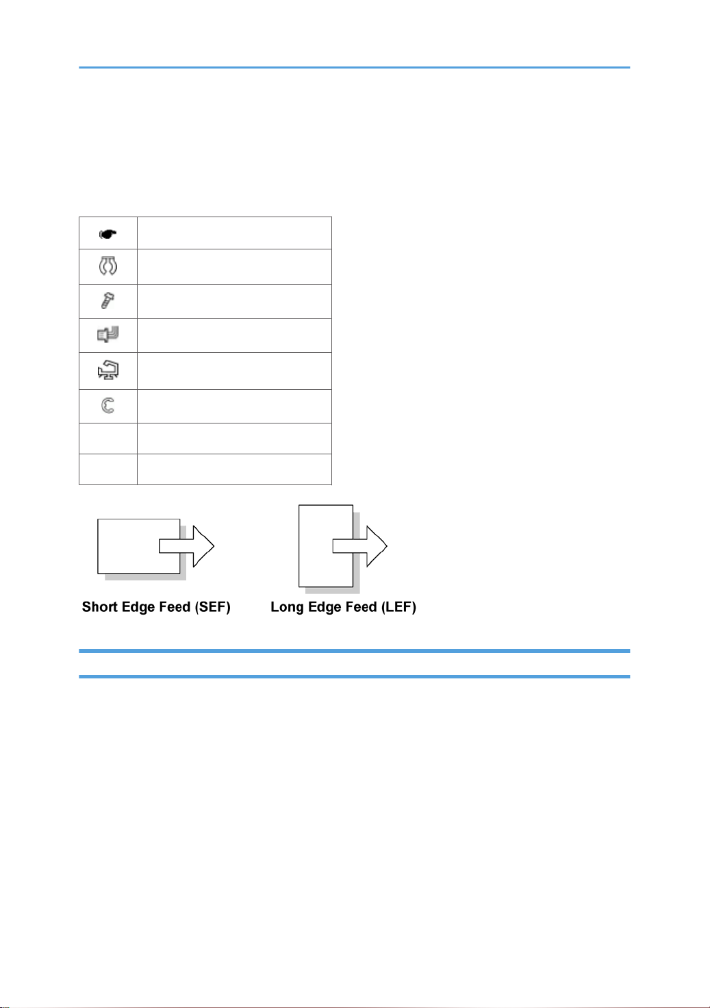
Symbols, Abbreviations and Trademarks
This manual
as follows:
SEF Short Edge Feed
LEF Long Edge Feed
uses several symbols and abbreviations. The meaning of those symbols and abbreviations are
See or Refer to
Clip ring
Screw
Connector
Clamp
E-ring
Trademarks
Microsoft®, Windows®,
States and /or other countries.
PostScript® is a registered trademark of Adobe Systems, Incorporated.
PCL® is a registered trademark of Hewlett-Packard Company.
Ethernet® is a registered trademark of Xerox Corporation.
PowerPC® is a registered trademark of International Business Machines Corporation.
Other product names used herein are for identification purposes only and may be trademarks of their
respective companies. We disclaim any and all rights involved with those marks.
and MS-DOS® are registered trademarks of Microsoft Corporation in the United
3
Page 6

TABLE OF CONTENTS
Safety Notices.....................................................................................................................................................1
Important Safety Notices...............................................................................................................................1
Laser Safety.....................................................................................................................................................2
Symbols, Abbreviations and Trademarks
Trademarks.....................................................................................................................................................3
.........................................................................................................3
1. Product Information
Specifications......................................................................................................................................................9
Machine Overview..........................................................................................................................................10
Component Layout.......................................................................................................................................10
Paper Path
Drive Layout..................................................................................................................................................12
Machine Configuration....................................................................................................................................13
....................................................................................................................................................11
2. Installation
Installation Requirements.................................................................................................................................15
Environment..................................................................................................................................................15
Machine Level..............................................................................................................................................16
Machine Space Requirement.....................................................................................................................16
Power Requirements....................................................................................................................................16
Installation Procedure..................................................................................................................................17
3. Preventive Maintenance
PM Intervals......................................................................................................................................................19
PM Parts........................................................................................................................................................19
Yield Counter................................................................................................................................................19
4. Replacement and Adjustment
Before You Start...............................................................................................................................................21
Special Tools....................................................................................................................................................22
Exterior Covers.................................................................................................................................................23
Front Cover...................................................................................................................................................23
Left Cover......................................................................................................................................................24
Rear Cover
Right Cover...................................................................................................................................................28
Top Cover.....................................................................................................................................................29
ADF....................................................................................................................................................................31
4
...................................................................................................................................................27
Page 7

ADF Unit........................................................................................................................................................31
Original Tray................................................................................................................................................32
ADF Feed Unit..............................................................................................................................................32
ADF Separation Pad....................................................................................................................................33
ADF Front Cover .........................................................................................................................................33
ADF Rear Cover...........................................................................................................................................34
ADF Cover....................................................................................................................................................34
ADF Motor....................................................................................................................................................35
Original Set Sensor......................................................................................................................................36
ADF Cover Open Sensor............................................................................................................................37
ADF Feed Sensor.........................................................................................................................................38
ADF Drive Board..........................................................................................................................................39
Scanner Unit.....................................................................................................................................................40
Operation Panel...........................................................................................................................................40
Scanner Top Cover......................................................................................................................................41
Scanner Carriage Unit.................................................................................................................................42
Exposure Lamp.............................................................................................................................................44
Lamp Stabilizer Board.................................................................................................................................45
Scanner Motor.............................................................................................................................................46
Laser Unit..........................................................................................................................................................48
Caution Decal Locations.............................................................................................................................48
Laser Unit......................................................................................................................................................48
Polygon Mirror Motor.................................................................................................................................49
Paper Feed and Exit.........................................................................................................................................51
Paper Feed Roller........................................................................................................................................51
Friction Pad...................................................................................................................................................52
Paper End Sensor.........................................................................................................................................52
By-pass Feed Roller.....................................................................................................................................52
By-Pass Feed Roller Friction Pad.................................................................................................................54
By-pass Feed Sensor...................................................................................................................................55
Paper Feed Clutch.......................................................................................................................................55
Relay Clutch.................................................................................................................................................57
Registration Clutch.......................................................................................................................................57
5
Page 8

Toner End Sensor.........................................................................................................................................57
Paper Exit Sensor.........................................................................................................................................58
Relay Sensor.................................................................................................................................................58
Inverter Sensor.............................................................................................................................................59
Registration Roller and Sensor....................................................................................................................59
Paper Transfer..................................................................................................................................................63
Transfer Roller..............................................................................................................................................63
Fusing................................................................................................................................................................64
Fusing Unit....................................................................................................................................................64
Thermostat....................................................................................................................................................66
Thermistor.....................................................................................................................................................67
Fusing Lamp..................................................................................................................................................68
Hot Roller......................................................................................................................................................69
Pressure Roller..............................................................................................................................................70
Hot Roller Stripper Pawls.............................................................................................................................70
Motors...............................................................................................................................................................72
Main Motor..................................................................................................................................................72
Duplex Motor (For M017)..........................................................................................................................72
Electrical Components.....................................................................................................................................74
Layout of PC Boards....................................................................................................................................74
PSU................................................................................................................................................................78
Charge Terminal Case................................................................................................................................82
Others................................................................................................................................................................83
Cooling Fan..................................................................................................................................................83
Speaker........................................................................................................................................................83
Quenching Lamp..........................................................................................................................................84
Image Adjustment.............................................................................................................................................85
Registration Adjustment...............................................................................................................................85
5. System Maintenance Reference
Service Program Mode....................................................................................................................................87
Overview......................................................................................................................................................87
Maintenance Mode Menu..........................................................................................................................87
Fax Service Test Menu..............................................................................................................................104
6
Page 9

Configuration and Maintenance Page .......................................................................................................106
Overview....................................................................................................................................................106
Firmware Updating........................................................................................................................................108
Checking the Machine Firmware Version...............................................................................................108
Updating the Controller Firmware...........................................................................................................108
Updating the Engine Firmware.................................................................................................................110
Updating the Boot Loader Firmware.......................................................................................................112
Updating Failure........................................................................................................................................112
FW Update Tool Messages......................................................................................................................112
6. Troubleshooting
Service Call Conditions.................................................................................................................................117
Summary....................................................................................................................................................117
Engine SC...................................................................................................................................................117
Image Problems.............................................................................................................................................124
Overview....................................................................................................................................................124
Test Page Printing......................................................................................................................................124
Test Pattern Printing....................................................................................................................................125
Dark lines in halftone areas at 75mm Intervals.......................................................................................126
Jam..................................................................................................................................................................127
Jam Sensor Layout.....................................................................................................................................127
Jam Message List.......................................................................................................................................128
7. Energy Saving
Energy Save...................................................................................................................................................131
Energy Saver Modes................................................................................................................................131
Paper Save.....................................................................................................................................................133
Effectiveness of Duplex/Combine Function............................................................................................133
7
Page 10

8
Page 11

1. Product Information
1
Specifications
See "Appendices" for the following information:
• "General Specifications"
"Printer"
•
• "Copier"
• "Scanner"
• "Fax"
• "Supported Paper Sizes"
9
Page 12
1. Product Information
1
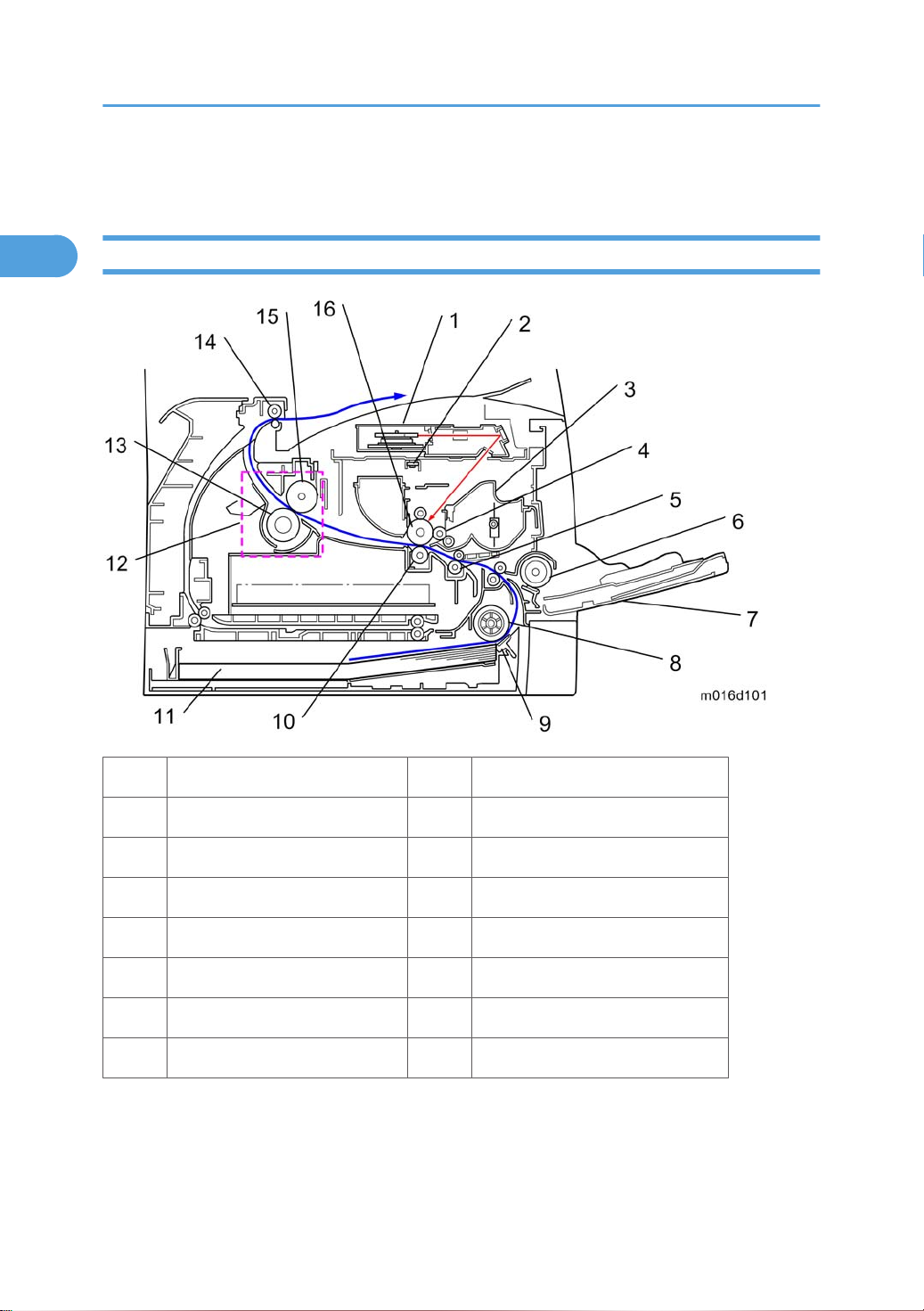
Machine Overview
Component Layout
10
1. Laser unit 9. Friction pad
2. Quenching lamp 10. Transfer roller
3. Cartridge (AIO-type) 11. Paper Tray
4. Development roller 12. Fusing Unit
5. Registration roller 13. Pressure Roller
6. By-pass feed roller 14. Paper exit roller
7. By-pass feed tray 15. Hot Roller
8. Paper feed roller 16. Drum
Page 13
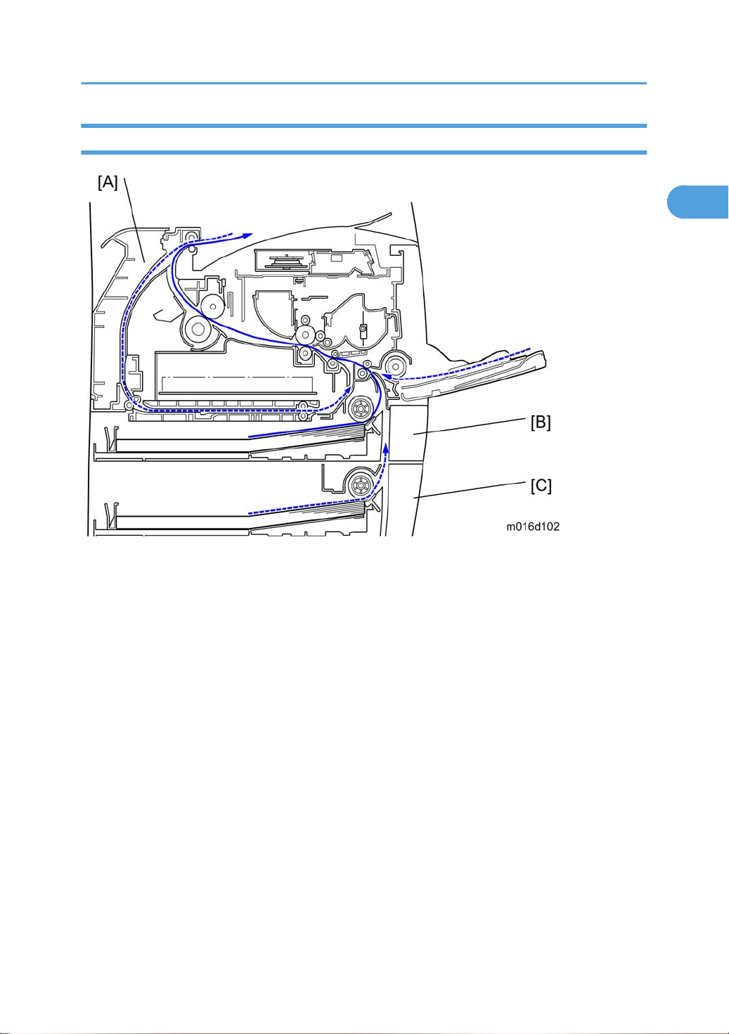
Paper Path
1
Machine Overview
[A] Duplex section (For M017)
[B] Standard paper tray unit
[C] Optional paper tray unit
11
Page 14
1. Product Information
1
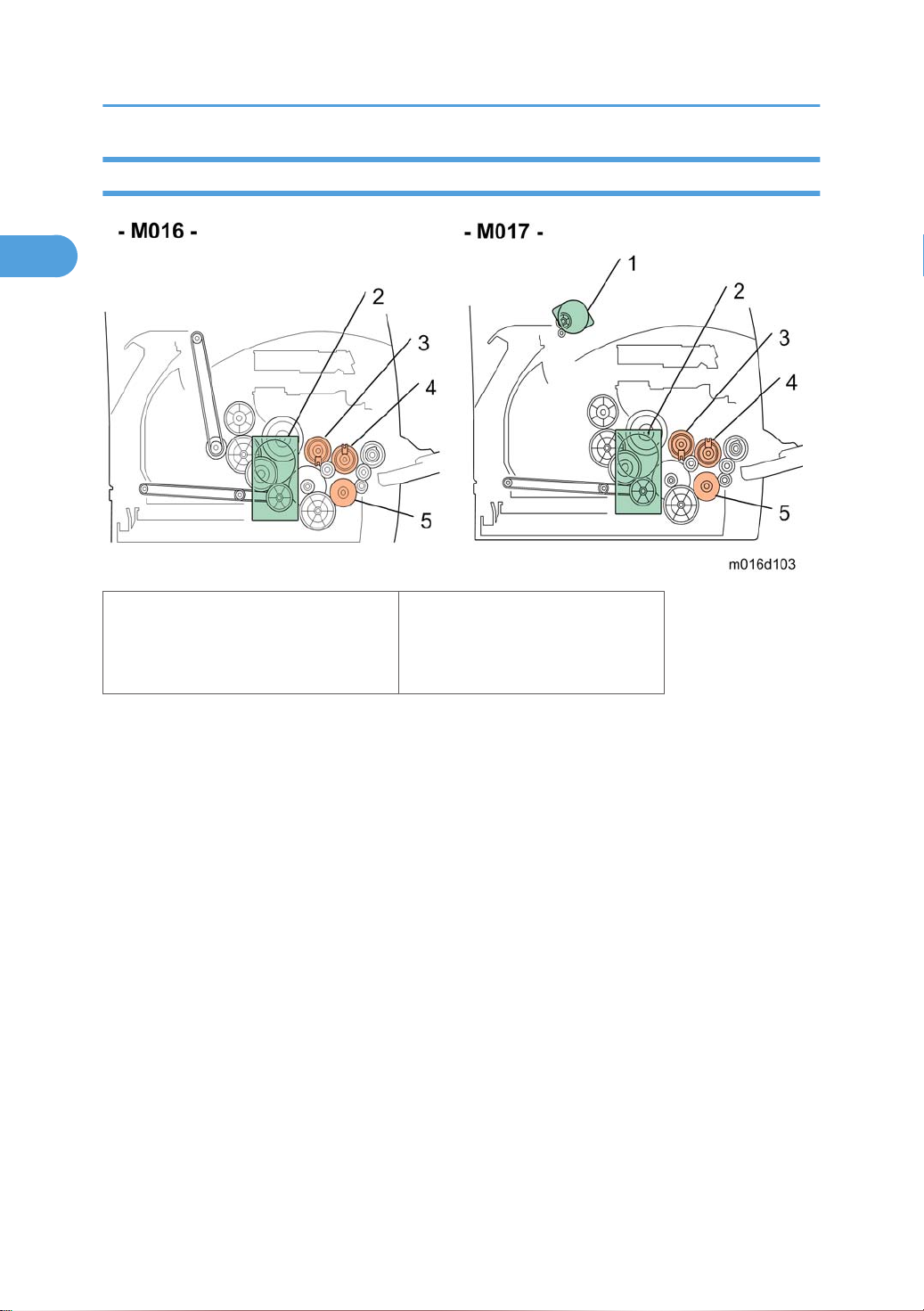
Drive Layout
1. Duplex Motor
2. Main Motor
3. Registration Clutch
4. Replay Clutch
5. Paper Feed Clutch
12
Page 15
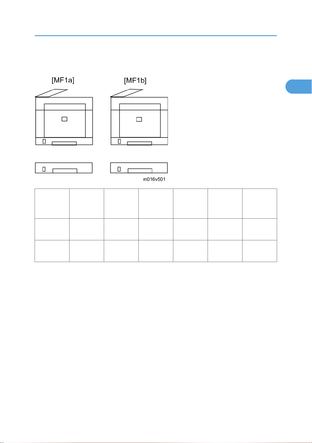
Machine Configuration
1
Machine Configuration
Models Duplex Unit
RN-MF1a
(M016)
RN-MF1b
(M017)
NA: Not Available
Optional
Memory
NA NA 250x1 Yes Yes Yes
Auto NA 250x1 Yes Yes Yes
Optional
Tray
(M355)
PCL PS Fax USB Host
13
Page 16

1. Product Information
1
14
Page 17
2. Installation
2
Installation Requirements
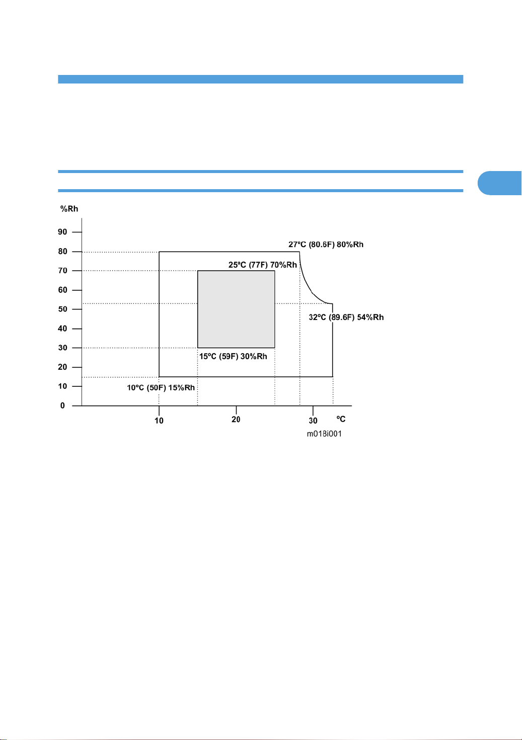
Environment
1. Temperature Rage: 10°C to 32°C (50°F to 89.6°F)
Humidity Range: 15% to 80% RH
2.
3.
Ambient Illumination: Less than 2,000 lux (do not expose to direct sunlight)
4. Ventilation: 3 times/hr/person
5. Do not put the machine in areas with sudden temperature changes. This includes:
• Areas directly exposed to cool air from air conditioning
• Areas directly exposed to heat from a heating system.
6. Do not put the machine in areas exposed to corrosive gas.
7. Do not install the machine at locations over 2,000 m (6,562 ft.) above sea level.
8. Put the machine on a strong, level base. (Tilting towards any side must be no more than 3 mm.)
9. Do not put the machine in areas with strong vibrations.
15
Page 18
2. Installation
2
Machine Level
Front to back: Within 5 mm (0.2") of level
Right to left: Within 5 mm (0.2") of level
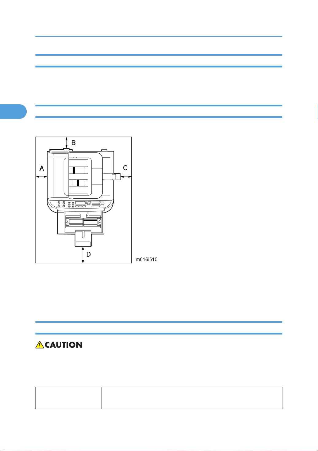
Machine Space Requirement
Put the machine near a power source with these clearances:
A: Over 10 cm (4")
B: Over 20 cm (7.9")
C: Over 20 cm (7.9")
D: Over 70 cm (27.6")
Power Requirements
• Make sure that the plug is tightly in the outlet.
• Avoid multi-wiring.
Make sure that you ground the machine.
•
Input voltage level
16
NA: 120 V, TW: 110 V, 60 Hz: Less than 10 A
EU/ Asia/ CHN: 220 V to 240 V, 50 Hz/60 Hz: Less than 5 A
Page 19

Permitted voltage fluctuation: 10%
2
Do not set anything on the power cord.
Installation Procedure
Refer to the "User Guide".
Installation Requirements
17
Page 20

2. Installation
2
18
Page 21
3. Preventive Maintenance
3
PM Intervals
PM Parts
There are no PM parts in this machine.
• Other than the three Yield Parts listed below, there are essentially no PM parts required for this product.
• These three items will need to be replaced in cases where their yield is near, however, given the ACV
(Average Copy Volume) for this product, these "yield parts*1 " are expected to outlast the working
life of the machine.
*1 "Yield Parts": Parts whose expected yield is longer than the machine lifetime when taking into
consideration the machine's ACV.
Description Expected Yield Q'ty/unit
Paper Feed Roller 120 K prints 1
Transfer Roller 120 K prints 1
Fusing Unit 120 K prints 1
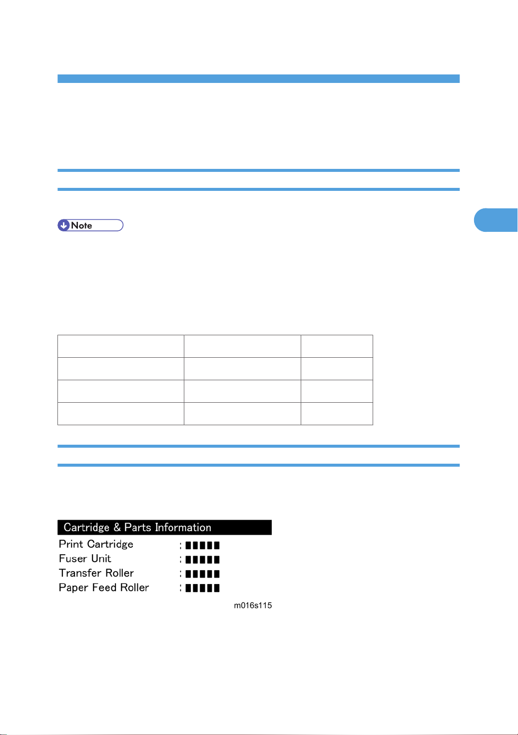
Yield Counter
Yield counters for each yield part can be checked by the following methods.
Configuration Page
These yield counters are printed under the supplies Info on the "Configuration Page" as shown above.
19
Page 22
3. Preventive Maintenance
3
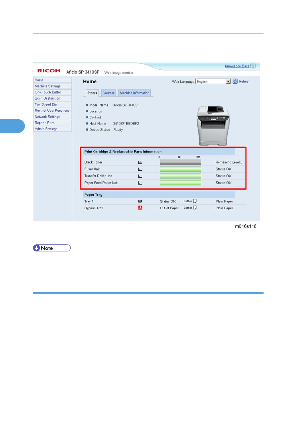
Web Image Monitor
These yield counters are displayed under the "Toner" on the "Status" page as shown above.
• The machine displays "Life End Feed Roller", "Life End Transfer Roller" or "Life End Fuser Unit" when
one of these counters reaches each yield.
Counter Reset
The process below shows how to reset the yield counters.
1. Enter the "Maintenance Mode".
Select "Engine Maintenance", and then press "OK" key.
2.
3. Select "Reset Fusing Unit Life", "Reset Transfer Roller Life" or "Reset Paper Feed Life" and then press
"OK" key.
4. Select "Execute" and then press "OK" key.
5. Exit the "Maintenance Mode".
20
Page 23

4. Replacement and Adjustment
4
Before You Start
• If there are printer jobs in the machine, print out all jobs in the printer buffer.
• Turn off the main power switch and unplug the machine before you do the procedures in this section.
21
Page 24

4. Replacement and Adjustment
4
Special Tools
• PC: Windows 2000/XP/Vista, Windows Server 2003/2003 R2, 2008.
•
USB or network cable
• A computer is necessary to update the firmware.
22
Page 25
Exterior Covers
4
Front Cover
Exterior Covers
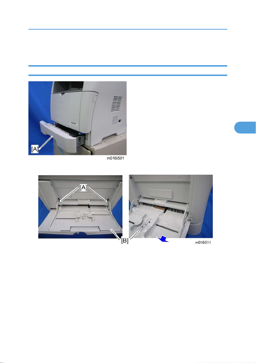
1. Pull out the standard paper tray [A].
2. Remove two tabs [A].
3. Pull out the bypass tray [B].
23
Page 26
4. Replacement and Adjustment
4
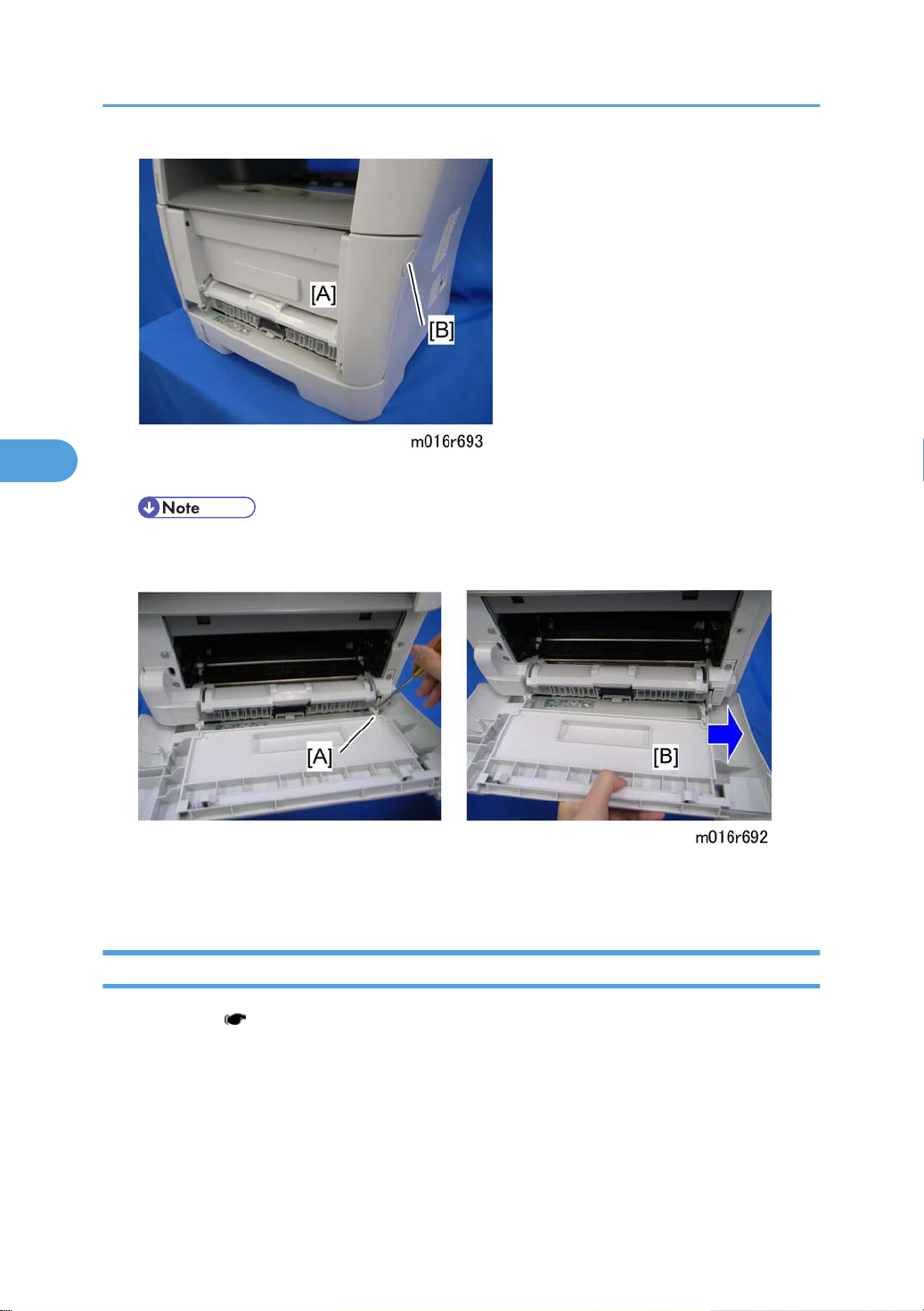
4. Open the front cover [A].
• To open the front cover, push the cover release button [B] and (carefully) pull the cover forward
and open (it hinges downward).
5. Push the right hinge [A] to release.
6. Front cover [B]
Left Cover
1. Front cover ( p.23)
24
Page 27
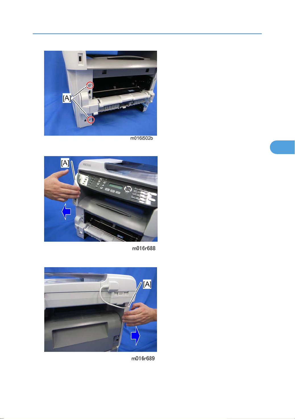
2. Remove two screws [A] on the left cover.
4
Exterior Covers
3. Pull the front upper part [A] of the left cover (as shown above) to release the hooks.
4. Pull the rear upper part [A] of the left cover (as shown above) to release the hooks.
25
Page 28
4. Replacement and Adjustment
4
5. Pull the front bottom part of the left cover [A] (as shown above) to release the hooks.
6. Remove the Left cover [A] as shown above.
• There are many hooks and tabs inside the left cover. See the images below in the Note section
before removing the left cover.
26
Page 29
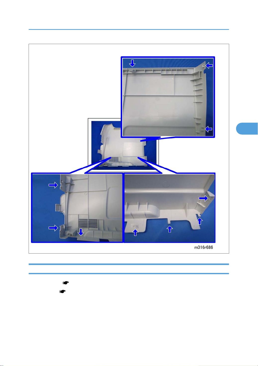
NOTE:
4
Exterior Covers
Rear Cover
1. Front cover ( p.23)
2. Left cover ( p.24)
27
Page 30
4. Replacement and Adjustment
4
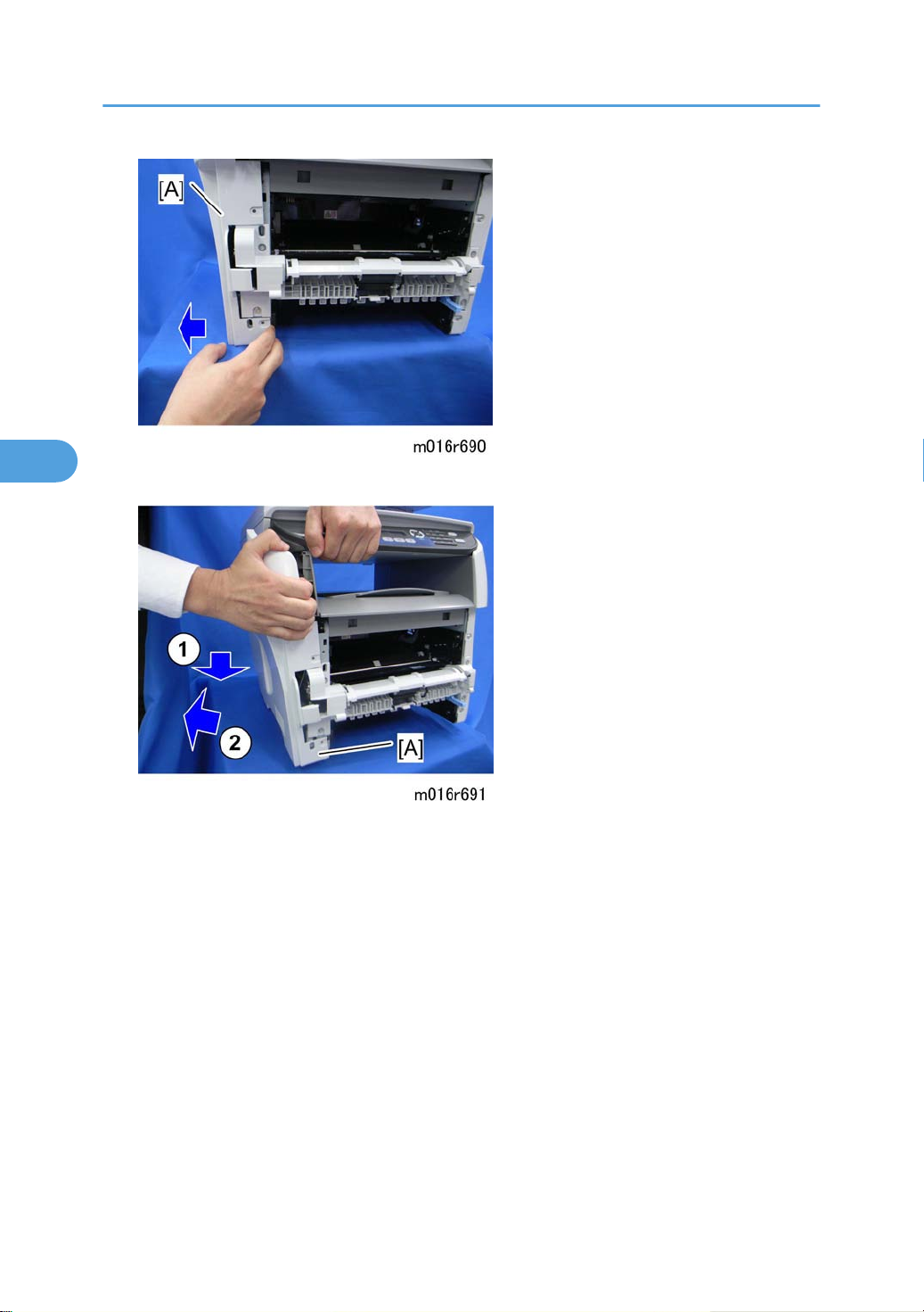
3. Open the rear cover [A]
4. Slide the shaft [B] in the direction of the blue arrow, and remove the rear cover [A].
Right Cover
1. Front cover ( p.23)
2. Rear cover ( p.27)
3. Right cover [A] ( x 3, hook at arrow mark)
• There are
before removing the right cover.
many hooks and tabs inside the right cover. See the images below in the Note section
28
Page 31

NOTE:
4
Exterior Covers
Top Cover
1. Front cover ( p.23)
2. Left cover ( p.24)
3. Rear cover ( p.27)
4. Scanner unit ( p.40)
29
Page 32

4. Replacement and Adjustment
4
5. Top cover [A] ( x 3, x 4)
When installing the top cover
• When re-installing the top cover, always verify that the two paperweights [A] are lifted. If they are
not lifted to fit into the paper slot, the paperweights [A] could be damaged.
• Make sure
cover. If these paperweights do not move smoothly, try installing the top cover again.
that these paperweights [A] can be moved smoothly (up and down) after installing the top
30
Page 33

ADF
4
ADF Unit
1. Left cover ( p.24)
ADF
2. Disconnect the ADF harness [A] and ground-wire [B] ( x 1).
3. Open the ADF unit [A]
31
Page 34

4. Replacement and Adjustment
4
4. Release the three hooks of the right hinge [A] with a screw driver, as shown above.
5. Lift the ADF unit.
Original Tray
1. Open the ADF cover [A].
2. Original tray [B] (Two tabs)
ADF Feed Unit
1. Open the ADF cover.
32
Page 35

2. Release the lock lever [A]
4
3. ADF feed unit [B]
ADF Separation Pad
1. Open the ADF cover.
ADF
2. ADF feed unit ( p.32)
3. ADF separation pad [A] (hook x 2, spring x 1)
ADF Front Cover
1. ADF unit ( p.31)
2. Original Tray ( p.32)
3. ADF feed unit ( p.32)
33
Page 36

4. Replacement and Adjustment
4
4. ADF front cover [A] ( x 1)
ADF Rear Cover
1. ADF unit ( p.31)
2. Original Tray ( p.32)
3. ADF feed unit ( p.32)
4. ADF rear cover [A] ( x 2)
ADF Cover
1. ADF unit ( p.31)
2. ADF front cover ( p.33)
3. ADF rear cover ( p.34)
34
Page 37

4. ADF top cover [A] (two tabs, two hooks)
4
ADF Motor
ADF
1. ADF unit ( p.31)
2. Original Tray ( p.32)
3. ADF feed unit ( p.32)
4. ADF front cover ( p.33)
5. ADF rear cover ( p.34)
6. ADF drive unit [A] ( x 4, all s)
35
Page 38

4. Replacement and Adjustment
4
7. ADF motor assembly [A] ( x 2)
8. ADF motor [A] ( x 2)
Original Set Sensor
1. ADF unit ( p.31)
2. ADF feed unit ( p.32)
3. ADF motor assembly ( p.35)
36
Page 39

4. Feed roller holder [A] ( x 1)
4
5. Upper guide [B] ( x 2)
ADF
6. Original set sensor [A] (hooks)
ADF Cover Open Sensor
1. Original tray ( p.32)
2. ADF rear cover ( p.34)
37
Page 40

4. Replacement and Adjustment
4
3. ADF cover open sensor [A] ( x 1, x 1)
ADF Feed Sensor
1. ADF unit ( p.31)
2. ADF feed unit ( p.32)
3. Sensor cover [A] ( x 2)
38
Page 41

4. ADF feed sensor [A] (hooks, x 1)
4
ADF Drive Board
1. Original tray ( p.32)
2. ADF rear cover ( p.34)
ADF
3. ADF drive board [A] (no screws, all plugs ( )s and hooks)
39
Page 42

4. Replacement and Adjustment
4
Scanner Unit
1. Front cover ( p.23)
2. Left cover ( p.24)
3. Rear cover ( p.27)
4. Slide the scanner unit [A] in the direction of the blue arrow, and remove it ( x 4, ground cable x 2,
flat cable x 1, x 3, x 3).
5. ADF unit ( p.31)
6. Operation Panel ( p.40)
7. Scanner Unit [A]
Operation Panel
1. Scanner unit ( p.40)
2. ADF unit ( p.31)
40
Page 43

3. Turn the scanner unit over.
4
4. Operation panel [A] ( x 3, hooks)
Scanner Top Cover
1. Scanner unit ( p.40)
2. Turn the scanner unit over.
Scanner Unit
3. Remove the six screws on the bottom of the scanner base [A].
41
Page 44

4. Replacement and Adjustment
4
4. Scanner top cover [A] (hooks)
Scanner Carriage Unit
1. Scanner unit ( p.40)
2. Scanner top cover ( p.41)
3. Slide the scanner carriage unit [A] to the right side.
42
Page 45

4. Loosen the timing belt [A] as shown above, and remove it.
4
Scanner Unit
5. Remove the flat cable [A] from the scanner carriage unit.
6. Bar holder [A] ( x 1)
43
Page 46

4. Replacement and Adjustment
4
7. Carriage bar [A] and scanner carriage unit [B]
Exposure Lamp
1. Scanner carriage unit ( p.42)
2. Carriage top cover [A] ( x 2, x 1)
44
Page 47

3. Exposure lamp [A] (hooks)
4
When reinstalling the exposure lamp
Scanner Unit
Place the lamp cord wires as shown above. Otherwise, the top cover could pinch the lamp cords and
damage them when reinstalling the top cover on the scanner carriage unit.
Lamp Stabilizer Board
1. Scanner carriage unit
45
Page 48

4. Replacement and Adjustment
4
2. Carriage bottom cover [A] ( x 2)
3. Lamp stabilizer [A] ( x 1)
Scanner Motor
1. Scanner carriage unit ( p.42)
46
Page 49

2. Scanner motor [A] ( x 3)
4
Scanner Unit
3. Carriage rail [A] ( x 2)
4. Ground plate [B] (double-sided tape)
5.
Conductance tape [C]
6. Scanner motor
47
Page 50

4. Replacement and Adjustment
4
Laser Unit
• Turn off the main power switch and unplug the machine before attempting any of the procedures in
this section. Laser beams can seriously damage your eyes.
Caution Decal Locations
Caution decal is attached as shown below.
• Be sure to turn off the main switch and disconnect the power plug from the power outlet before
beginning any disassembly or adjustment of the laser unit. This machine uses a class IIIB laser beam
with a wavelength of 648 to 663 nm and an output of 9 mW. The laser can cause serious eye injury.
Laser Unit
1. Front cover ( p.23)
2. Left cover ( p.24)
3. Rear cover ( p.27)
4. Scanner unit ( p.40)
5. Top cover ( p.29)
48
Page 51

6. Laser unit [A] ( x 3, ground screw x 3, x 2)
4
Polygon Mirror Motor
• Turn off the main switch and unplug the machine before attempting any of the procedures in this
section. Laser beams can seriously damage your eyes.
Laser Unit
1. Laser unit ( p.48)
2. Polygon mirror cover [A] ( x 2)
49
Page 52

4. Replacement and Adjustment
4
3. Polygon mirror motor [A] ( x 4, x 1)
• Never touch the surface of the mirror with bare hands.
50
Page 53

Paper Feed and Exit
4
Paper Feed Roller
1. Pull out the standard paper tray.
2. Remove the AIO.
Paper Feed and Exit
3. Set the machine with the rear side facing down, resting on the table.
4. Slide the paper feed shaft [A] to the left side ( x 2).
5. Slide the paper feed roller [B] to right side, and remove it (hook).
After installing a new paper feed roller
1. Enter the "Maintenance Mode".
2. Select "Engine Maintenance", and then press "OK" key.
3.
Select "Reset Paper Feed Life" and then press "OK" key.
4. Select "Execute" and then press "OK" key.
51
Page 54

4. Replacement and Adjustment
4
Friction Pad
1. Remove the paper tray unit from the machine before removing the friction pad.
2. Friction pad [A] (2 hooks, 1 spring)
When reinstalling the friction pad follow this order:
Replace the spring.
1.
2. Insert the right side of the friction pad first, followed by the left side.
3. Gently push the friction pad down into the slot and then pull forward very slightly.
Paper End Sensor
1. Set the machine with the rear side facing down, resting on the table.
2. Paper end sensor [A] (hooks, x 1)
By-pass Feed Roller
1. Front cover ( p.23)
52
Page 55

2. Left cover ( p.24)
4
3. Right cover ( p.28)
4. Pull out the paper tray.
5. By-pass lower guide plate [A] ( x 4, x 2)
NOTE:
• Reinstall the by-pass lower guide plate [A] while pressing the spring [B].
Paper Feed and Exit
Be careful for the spring [B] and the ground plate [C] not to fall inside the machine during
•
reinstallation.
53
Page 56

4. Replacement and Adjustment
4
6. By-pass upper guide plate [A] (hooks)
7. By-pass solenoid cover, by-pass solenoid [B] ( x 1)
8. Gear [C] (hook)
9. Slide the by-pass feed roller shaft [A] to the left side, and remove it.
10. Remove the metal cover [B] from the by-pass feed roller [C].
By-Pass Feed Roller Friction Pad
1. By-pass feed roller ( p.52)
54
Page 57

2. By-pass feed roller friction pad [A] (hooks, spring x 1)
4
By-pass Feed Sensor
1. Front cover ( p.23)
2. Right cover ( p.28)
Paper Feed and Exit
3. By-pass feed sensor [A] (hooks, x 1)
Paper Feed Clutch
1. Top cover ( p.29)
2. Scanner unit ( p.40)
3. ECB ( p.74)
4. Controller board ( p.76)
5. FCU ( p.77)
55
Page 58

4. Replacement and Adjustment
4
6. Release all harnesses [A] from the clamps.
7. Harness guide plate [B] ( x 2)
8. Drive unit [A] ( x 5, x 1, x 2, timing belt)
9. Paper feed clutch [A] ( x 1, x 1)
56
Page 59

Relay Clutch
4
1. Drive unit ( p.55 "Paper Feed Clutch")
2. Relay clutch [A] ( x 1)
Paper Feed and Exit
Registration Clutch
1. Drive unit ( p.55 "Paper Feed Clutch")
2. Registration clutch [A] ( x 1)
Toner End Sensor
1. Drive unit ( p.55 "Paper Feed Clutch")
57
Page 60

4. Replacement and Adjustment
4
2. Reflective sensor with bracket [A] ( x 1)
3. Reflective sensor [B]
Paper Exit Sensor
1. Rear cover ( p.27)
2. Paper exit sensor [A] ( x 1, hooks)
Relay Sensor
1. Rear cover ( p.27)
58
Page 61

2. Relay sensor [A] ( x 1, hooks)
4
Inverter Sensor
1. Duplex transport guide ( p.78 "PSU")
Paper Feed and Exit
2. Inverter sensor [A] ( x 1, hooks)
Registration Roller and Sensor
1. Pull out the paper tray.
2. PSU ( p.78 "PSU")
3. Paper feed clutch ( p.55 "Paper Feed Clutch")
4. Relay clutch ( p.57)
5. Registration clutch ( p.57)
59
Page 62

4. Replacement and Adjustment
4
6. Heat insulating plate [A] ( x 2)
7. Exit roller base [B] ( x 2)
8. Imaging unit base [A] ( x 4)
9. Remove the four screws in the right frame [A].
60
Page 63

10. Remove the four screws in the left frame [A].
4
Paper Feed and Exit
11. Registration unit [A]
12. Upper guide plate [B]
13. Registration roller [A]
61
Page 64

4. Replacement and Adjustment
4
14. Registration sensor [A]
62
Page 65

Paper Transfer
4
Transfer Roller
1. Front cover ( p.23)
2. Remove the AIO.
Paper Transfer
3. Remove the transfer roller [A] (Bushing x 1, spring x 2, gear x 1) as shown above.
• Do not touch the transfer roller surface, when reinstalling the new transfer roller.
After installing a new transfer roller
1. Enter the "Maintenance Mode".
2. Select "Engine Maintenance", and then press "OK" key.
3.
Select "Reset Transfer Roller Life" and then press "OK" key.
4. Select "Execute" and then press "OK" key.
63
Page 66

4. Replacement and Adjustment
4
Fusing
• Switch off the main power, unplug the machine from its power source, and allow the fusing unit to
cool before removing it.
Fusing Unit
1. Front cover ( p.23)
2. Left cover ( p.24)
3. Rear cover ( p.27)
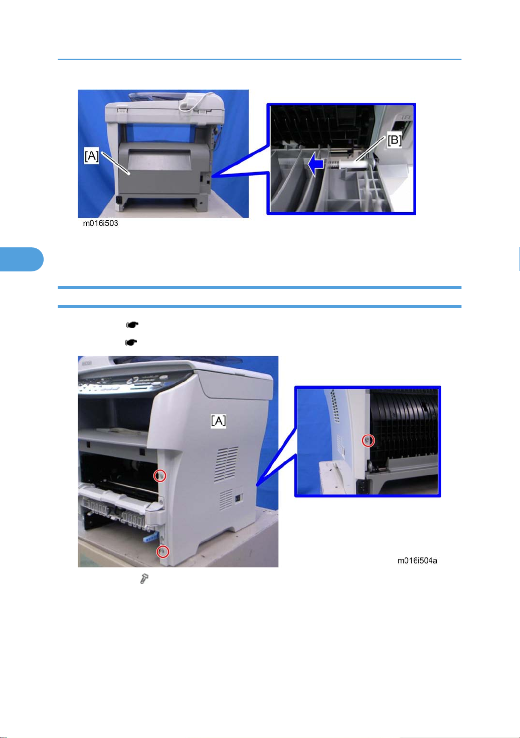
4. Entrance guide [A] ( x 1)
5. Disconnect the three harnesses ( x 2)
64
Page 67

Fusing
4
6. Pass the cable [A] through the hole [B] inside the machine.
7. Fusing unit [C] ( x 4)
NOTE:
Make sure that the two bushings [A] remain be setting.
65
Page 68

4. Replacement and Adjustment
4
Reinstallation
Pass the cable [A] of fusing unit through the hole [B] outside, after setting the fusing unit.
After installing a new fusing unit
1. Enter the "Maintenance Mode".
2. Select "Engine Maintenance", and then press "OK" key.
Select "Reset Fusing Unit Life" and then press "OK" key.
3.
4. Select "Execute" and then press "OK" key.
Thermostat
• Do not recycle a thermoswitch that is already opened. Safety is not guaranteed if you do this.
1. Fusing unit [A] ( x 3)
2. Fusing upper cover [A] ( x 4)
66
Page 69

3. Thermostat [A] ( x 2)
4
Thermistor
1. Fusing unit ( p.64)
Fusing
2. Fusing front cover [A] ( x 2)
3. Thermistor [A] ( x 1)
67
Page 70

4. Replacement and Adjustment
4
Fusing Lamp
1. Fusing Unit ( p.64)
2. Fusing side covers [A] ( x 2 each)
3. Ground-wires ( x 1 each)
4. Fusing lamp [A]
68
Page 71

When reinstall the fusing lamp
4
The flat terminal [A] must be placed on the right side of the fusing unit (fusing cable side).
Hot Roller
Fusing
1. Fusing lamp ( p.68)
2. Brackets [A] ( x 2)
69
Page 72

4. Replacement and Adjustment
4
3. Hot roller [A] (C-ring x 2, gear x 1, bushing x 2)
Pressure Roller
1. Hot roller ( p.69)
2. Pressure roller [A] (Bearing x 2)
Hot Roller Stripper Pawls
1. Fusing unit ( p.64)
2. Fusing unit upper cover ( p.66)
70
Page 73

3. Metal holders [A] (1 holder for each pawl: x 2 each)
4
Fusing
4. Hot roller stripper pawls [A] (1 spring for each pawl)
71
Page 74

4. Replacement and Adjustment
4
Motors
Main Motor
1. Front cover ( p.23)
2. Left cover ( p.24)
3. Harness guide [A] ( x 2)
4. Main motor [B] ( x 4, x 1)
Duplex Motor (For M017)
1. Front cover ( p.23)
2. Left cover ( p.24)
3. Rear cover ( p.27)
4. Right cover ( p.28)
5. Top cover ( p.29)
72
Page 75

6. Duplex motor [A] ( x 2, x 1)
4
Motors
73
Page 76

4. Replacement and Adjustment
4
Electrical Components
Layout of PC Boards
[A] ECB (Engine Controller Board)
[B] Controller Board
[C] FCU (Fax Control Unit) - behind the main controller board
[D] USB Board
ECB (Engine Controller Board)
1. Front cover ( p.23)
2. Left cover ( p.24)
74
Page 77

Electrical Components
4
3. ECB [A] ( x 4, all s)
• Do not connect any connectors to CN181 when reinstalling the ECB [A]. CN181 is only used
for factory.
• Do not change the dip switch. The dip switch is only for factory use.
4. EEPROM (Electronically Erasable Programmable Read Only Memory) [A]
When installing the new ECB (Engine Controller Board)
75
Page 78

4. Replacement and Adjustment
4
1. Remove the EEPROM from the old ECB.
2. Install it on the new ECB after replacing the ECB.
3. Replace the EEPROM if the EEPROM on the old ECB is defective.
• Keep the EEPROM away from any objects that can cause static electricity. Static electricity can
damage EEPROM data.
Make sure that the EEPROM is correctly installed on the ECB.
•
EEPROM
• Replacement procedures for the new EEPROM are included in the "ECB (Engine Controller Board)"
replacement procedure. Refer to "ECB (Engine Controller Board)" for details.
• Do the following settings after installing a "new" EEPROM.
-Input the PnP Name, Destination in Maintenance mode.
-Adjust registration in Maintenance mode.
-Input serial number on the serial number input display after installing the new EEPROM
• Ask your supervisor about how to access the serial number input display.
Controller Board
• Risk of explosion if battery is replaced by an incorrect type. Dispose of used batteries according to
the instructions.
1. ECB ( p.74)
76
Page 79

2. Controller board [A] ( x 4, flat cable x 1, all s)
4
FCU
1. ECB ( p.74)
2. Controller board( p.76)
Electrical Components
3. Controller board bracket [A] ( x 3)
4. FCU [A] ( x 4)
77
Page 80

4. Replacement and Adjustment
4
USB Host Board
1. Left cover ( p.24)
2. USB host board [A] ( x 2, x 1)
PSU
1. Pull out the standard paper tray.
2. Front cover ( p.23)
3. Left cover ( p.24)
4. Rear cover ( p.27)
5. Right cover ( p.28)
6. Scanner unit ( p.40)
7. Top cover ( p.29)
8. ECB ( p.74)
9. Controller board bracket ( p.77)
10. Drive unit ( p.55 "Paper Feed Clutch")
78
Page 81

Electrical Components
4
11. Disconnect three connectors in left frame( x 1)
12. Bracket [A] ( x 2)
13. Main power switch bracket [A] in right frame( x 2)
14. Remove the main power cord [B] as sown above( x 2).
15. Remove the ground wire and two connectors.
79
Page 82

4. Replacement and Adjustment
4
16. Rear low cover [A] ( x 3)
17. Entrance guide [A]
18. Fusing Unit( p.64)
19. For M017 only: Duplex transport guide [A] ( x 2)
80
Page 83

Electrical Components
4
20. For M017 only: Set the machine with the front side facing down, resting on the table.
21. For M017 only: Release the link [A] ( x 1)
22. For M017 only: Duplex cover [A] ( x 4, x 1, gear x 1)
81
Page 84

4. Replacement and Adjustment
4
23. PSU [A] ( x 4, x 1)
Charge Terminal Case
1. Right cover ( p.28)
2. Charge terminal case [A] with the harness ( x 2, x 1, hooks)
3. Remove the harness [A] ( x 4).
4. Remove the four springs and terminal pins [B].
5.
Charge terminal case [C]
82
Page 85

Others
4
Cooling Fan
1. Right cover ( p.28)
2. Cooling fan [A] ( x 2, x 1)
Others
• Install the Cooling fan [A] with its decal facing the outside of the machine.
Speaker
1. Left cover ( p.24)
2. Speaker [A] ( x 2, x 1, x 1)
83
Page 86

4. Replacement and Adjustment
4
Quenching Lamp
1. Top Cover ( p.29)
2. Release two hooks of the quenching lamp with the case [A], and remove it.
3. Remove the quenching lamp [A] from the case (hook x 3).
84
Page 87

Image Adjustment
4
Image Adjustment
Registration Adjustment
User Adjustment
The paper registration can also be adjusted with the user mode ("Engine Maintenance Registration"). For
details, see the "User Guide".
Service Adjustment
1. Print the test page ( p.124).
• Print out the test pattern before changing the paper registration setting.
2. Enter the "Maintenance Mode".
3. Select "Engine Maintenance", and then press "OK" key.
4. Select the "Registration", and then press "OK" key.
(1): Feed Direction
(2): Vertical Adjustment
(3): Horizontal Adjustment
(4): Print Area
5. Press the "Up" or "Down" keys to set the registration value (mm).
85
Page 88

4. Replacement and Adjustment
4
• Increase the value to shift the print area in the plus direction.
• Decrease to shift in the minus direction.
6. Adjust the margins of the test page so that they are equal in size.
86
Page 89

5. System Maintenance Reference
5
Service Program Mode
Overview
This model has several service menus. Each service menu has several adjustment items. This section explains
how to enter each service menu and what you can do in each service menu.
Maintenance Mode Menu
Selecting an Item
To select an item, press the "Up" or "Down" key.
Going into the Next Level/ Returning to the Previous Level
• To go into the next level of an item, select an item then press the "OK" key.
• To return to the previous level of an item, press the "Return" key.
Exiting the Maintenance Mode Menu
To exit the maintenance mode menu, press the "Clear/Stop" or "Return" key until the "Ready" display
appears.
Menu List
Display Info
Model Name
CTL FW Ver. Displays the Firmware Version
FAX FW Ver. Displays the FAX Firmware Version.
FW Ver.
Engine FW Version Displays the Engine Firmware Version
Displays the Model Name, Depends on Engine
Firmware Settings
PDL FW Ver. Displays the PDL Firmware Version.
87
Page 90

5. System Maintenance Reference
5
Display Info
Counter
Print Reports
G3 Protocol dump list
Engine Maintenance
Printer Counter
Scanner Counter
Jam Counter
Displays the following counters of the printer engine.
Total Page
Displays the sum total of scanner counters for each
mode.
Total Page/ Black Page/ Color Page
/ ADF Used
Displays the number of paper jams at each location.
Total/ ADF/ Outer/ Inner/ Tray1 Misfeed/
Tray2 Misfeed/ Duplex Misfeed/ Bypass Tray
Misfeed
G3 protocol dump of the latest communication is
printed.
Off (Default)/ Error/ On
88
NA Model: RICOH/ 'nul'
EU Model: RICOH/ NRG/ LANIER
PNP Name
ASIA Model: RICOH/ LANIER
China Model: RICOH
Sets the destination and updates the engine setting.
Destination
JPN/ NA/ EU (Default)/ ASIA/ China/ TAIWAN/ COREA
Page 91

Engine Maintenance
5
Registration
Horiz. Tray1
Vert. Tray1 Plain
Paper
Vert. Tray1 Thick
Paper
Vert. Tray1 Thin
Paper
Service Program Mode
Adjusts the horizontal registration for tray 1. If the machine
settings are reset to the factory defaults, this value does not
change.
[-40 to 40 / 0 (Default) / 0.1 mm/step]
Adjusts the vertical registration of plain paper for tray1. If the
machine settings are reset to the factory defaults, this value
does not change.
[-40 to 40 / 0 (Default) / 0.1 mm/step]
Adjusts the vertical registration of thick paper for tray 1. If the
machine settings are reset to the factory defaults, this value
does not change.
[-40 to 40 / 0 (Default) / 0.1 mm/step]
Adjusts the vertical registration of thin paper for tray 1. If the
machine settings are reset to the factory defaults, this value
does not change.
[-40 to 40 / 0 (Default) / 0.1 mm/step]
Registration
Horiz. Tray2
Vert. Tray2 Plain
Paper
Vert. Tray2 Thin
Paper
Vert. Tray2 Thick
Paper
Adjusts the horizontal registration for tray 1. If the machine
settings are reset to the factory defaults, this value does not
change.
[-40 to 40 / 0 (Default) / 0.1 mm/step]
Adjusts the vertical registration of plain paper for tray 2. If the
machine settings are reset to the factory defaults, this value
does not change.
[-40 to 40 / 0 (Default) / 0.1 mm/step]
Adjusts the vertical registration of thin paper for tray 2. If the
machine settings are reset to the factory defaults, this value
does not change.
[-40 to 40 / 0 (Default) / 0.1 mm/step]
Adjusts the vertical registration of thick paper for tray 2. If the
machine settings are reset to the factory defaults, this value
does not change.
[-40 to 40 / 0 (Default) / 0.1 mm/step]
89
Page 92

5. System Maintenance Reference
5
Engine Maintenance
Horiz.Bypass
Vert. Bypass Plain
Paper
Registration
Vert. Bypass Thick
Paper
Vert. Bypass Thin
Paper
Adjusts the horizontal registration for the bypass tray. If the
machine settings are reset to the factory defaults, this value
does not change.
[-40 to 40 / 0 (Default) / 0.1 mm/step]
Adjusts the vertical registration of plain paper for the bypass
tray. If the machine settings are reset to the factory defaults,
this value does not change.
[-40 to 40 / 0 (Default) / 0.1 mm/step]
Adjusts the vertical registration of thick paper for the bypass
tray. If the machine settings are reset to the factory defaults,
this value does not change.
[-40 to 40 / 0 (Default) / 0.1 mm/step]
Adjusts the vertical registration of thin paper for t the bypass
tray. If the machine settings are reset to the factory defaults,
this value does not change.
[-40 to 40 / 0 (Default) / 0.1 mm/step]
Registration
Horiz. Dup. Back
Vert. Dup. Plain
Paper
Vert. Dup. Thin
Paper
Vert. Dup. Thick
Paper
Adjusts the horizontal registration the back side in duplex
mode. If
this value does not change.
[-40 to 40 / 0 (Default) / 0.1 mm/step]
Adjusts the vertical registration of plain paper for the back side
in duplex
defaults, this value does not change.
[-40 to 40 / 0 (Default) / 0.1 mm/step]
Adjusts the vertical registration of thin paper for the back side
in duplex
defaults, this value does not change.
[-40 to 40 / 0 (Default) / 0.1 mm/step]
Adjusts the vertical registration of thick paper for the back side
in
defaults, this value does not change.
[-40 to 40 / 0 (Default) / 0.1 mm/step]
the machine settings are reset to the factory defaults,
mode. If the machine settings are reset to the factory
mode. If the machine settings are reset to the factory
duplex
mode. If the machine settings are reset to the factory
90
Page 93

Engine Maintenance
5
Service Program Mode
00* – 7F
Brand ID
Fuser SC Reset This button is for resetting an SC related with the fusing errors.
Bypass Tray
Priority
Reset Transfer
Roller Life
Reset Paper
Feed Roller Life
Reset Fusing Unit
Life
Motor Rotation
Time
Print Cartridge
Info
Displays the current brand ID number.
Do not change this setting (Designed for Factory Use).
Turns on or off the paper priority feeding from the bypass tray.
[On or Off]
Clears the EM counter of the transfer roller.
Clears the EM counter of the paper feed roller.
Clears the EM counter of the fusing unit.
Displays the main motor rotation time.
Kind ID Displays the toner cartridge (AIO) information (Kind ID).
Toner End History
Refill Flag Status
Displays the toner cartridge (AIO) information (Toner
End History).
Displays the toner cartridge (AIO) information (Refill
flag status).
OPC Life Info
Unit Print Counter
OPC Rotation Time Displays the OPC life information (OPC rotation time).
Pre-OPC Rotation Time
OPC Alert Status Displays the OPC life information (Alert status)
OPC Pre-Alert Status Displays the OPC life information (Pre-Alert status)
Displays the toner cartridge (AIO) information (Unit Print
Counter).
Displays the OPC life information (Pre-OPC rotation
time)
91
Page 94

5. System Maintenance Reference
5
Engine Maintenance
Remain of Transfer Roller Displays the total counter (Remain of Transfer Roller).
Transfer Roller - Time Displays the EM counter (Transfer Roller: Time).
Transfer Roller - Pages Displays the EM counter (Transfer Roller: pages).
EM Counter Info
Total Counter
Info
Clear Engine
Memory
SC559
Detection
EM Life Display
Remain of Paper Feed
Roller
Paper Feed Roller - Pages Displays the EM counter (Paper Feed Roller: pages).
Remain of Fusing Unit Displays the total counter (Remain of Fusing Unit).
Fusing Unit - Time Displays the EM counter (Fusing Unit: time).
Fusing Unit - Pages Displays the EM counter (Fusing Unit: pages).
Engine Counter Displays the total counter (Engine).
Resets the engine settings stored in the EEPROM to factory default.
[On or Off (Default)]
Sets the display of alert when each EM parts yield of this machine is reached.
[On or Off (Default)]
Displays the total counter (Remain of Paper Feed Roller).
92
Page 95

Engine Maintenance
5
Service Program Mode
Main Motor Output check (Main Motor)
Middle clutch Output check (Relay Clutch)
Tray1 clutch Output check (Paper Feed Clutch)
Bypass solenoid Output check (Bypass solenoid)
Regist clutch Output check (Registration Clutch)
Reserve clutch Output check (Reserve clutch)
Output check
Fan High Speed Output check (Fan High Speed)
Fan Low Speed Output check (Fan Low Speed)
Erase Lamp Output check (Quenching Lamp)
Polygon Motor Output check (Polygon Motor)
Tray2 Motor Output check (Tray2 Motor)
Dup Motor Normal Output check (Duplex Motor Normal)
Dup Motor Reserve Output check (Duplex Motor Reverse)
93
Page 96

5. System Maintenance Reference
5
Engine Maintenance
Vert. Tray1 Plain Paper Adjusts the amount of paper buckle at the registration
Vert. Tray1 Thick Paper
Vert. Tray1 Thin Paper
roller for each tray and paper type.
[-8 to 8 / 0 (Default) / 1 mm/step]
Adjusts the amount of paper buckle at the registration
roller for each tray and paper type.
[-8 to 8 / -2 (Default) / 1 mm/step]
Paper Buckle
Amount
Fusing Unit
Temperature
Vert. Bypass Plain Paper
Vert. Bypass Thick Paper
Vert. Bypass Thin Paper
Vert. Tray2 Plain Paper
Vert. Tray2 Thin Paper
Vert. Tray2 Thick Paper
Vert. Dup. Plain Paper
Vert.Dup. Thin Paper
Vert Dup. Thick Paper
Plain Paper
Thick1 Paper
Thick2 Paper
Adjusts the amount of paper buckle at the registration
roller for each tray and paper type.
[-8 to 8 / 0 (Default) / 1 mm/step]
Adjusts the amount of paper buckle at the registration
roller for each tray and paper type.
[-8 to 8 / 0 (Default) / 1 mm/step]
Adjusts the amount of paper buckle at the registration
roller for each tray and paper type.
[-8 to 8 / 0 (Default) / 1 mm/step]
Adjusts the fusing temperature for plain paper.
[150 to 190 / 175 (Default) / 5°C/step]
Adjusts the fusing temperature for thick 1 paper.
[160 to 200 / 185 (Default) / 5°C /step]
Adjusts the fusing temperature for thick 2 paper.
[160 to 200 / 185 (Default) / 5°C/step]
Standby
Adjusts the fusing temperature in the standby mode.
[120 to 175 / 155 (Default) / 1°C/step]
Adjusts the fusing temperature in the low power mode.
Low Power
[80 to 135 / 120 (Default) / 5°C/step]
94
Page 97

Engine Maintenance
5
Service Program Mode
Fusing Unit
Temperature
Charge Bias
Developer Bias
Trans. Roller Bias
Subscan
Magnification
Thin Paper
Adjusts the fusing temperature for thin paper.
[140 to 165 / 150 (Default) / 5°C/step]
Adjusts the fusing temperature for envelope.
Envelope
[170 to 200 / 200 (Default) / 5°C/step]
Adjusts the fusing temperature for postcard.
Postcard
[160 to 200 / 185 (Default) / 5°C/step]
Adjusts the fusing temperature for recycled paper.
Recycled
[150 to 180 / 160 (Default) / 5°C/step]
Adjusts the charge bias.
[1100 to 1300 / 1200 / 20 /step]
Adjusts the developer bias.
[270 to 330 / 300 / 15 /step]
Adjusts the transfer roller bias.
[-6 to 6 / 0 / 1 /step]
Adjusts the sub scan magnification.
[-8 to 8 / 0 / 1 /step]
Toner Near End
To Toner End
Sheets
Dot Count
Adjusts the printable sheets between "toner near end" to
"toner end".
[0 to 255 / 200 / 1 sheet/step]
Adjusts the printable dot count between "toner near end"
to "toner end".
[0 to 255 / 100 / 1 dot/step]
95
Page 98

5. System Maintenance Reference
5
Engine Maintenance
Sets the machine operation at "waste toner full" of the
refilled AIO.
[On or Off (Default)]
Waste toner
disposal
Test Pattern Prints the test pattern.
Curl Control
mode
Adjust of Charge
Bias
Independent-Supply
Toner
Corrects the face curl of paper.
0: OFF (28ppm)
1: Sets the engine speed at 14ppm after printing 1 minute.
2: Sets the engine speed at 14ppm.
3 to 255: not available
[0 to 255 / 0 / 1 /step]
Charge bias correction for dirty background
0: OFF (Default)
1: ON
2 to 255: not available
• With main motor rotation count feature, machine
set to stop printing after print total exceeds a
can be
certain set value. If print count exceeds this value,
then "Replace Print Cartridge" remains in display.
Then a new AIO cartridge must be installed. This
feature is a safety measure to prevent the used toner
tank from becoming full (there is no toner overflow
detection mechanism).
96
Scan Maintenance
Mono Compression
Setting
[0 to 255 / 0 / 1 /step]
Sets the monochrome compression type for scanning.
MH (Default)/ MR/ MMR
Page 99

Scan Maintenance
5
Service Program Mode
Regist Adjust
Size Adjust
ADF Main Reg.
Adjusts the ADF Scan main-scan registration.
[-2.0 to 2.0 / 0 (Default)/ 0.1 mm/step]
Adjusts the ADF Scan sub-scan registration.
ADF Sub Reg.
[-2.0 to 2.0 / 0 (Default)/ 0.1 mm/step]
Adjusts the Flatbed Scan main-scan registration.
Flatbed Main Reg.
[-2.0 to 2.0 / 0 (Default)/ 0.1 mm/step]
Adjusts the Flatbed Scan sub-scan registration.
Flatbed Sub Reg.
[-2.0 to 2.0 / 0 (Default)/ 0.1 mm/step]
Adjusts the ADF Scan main-scan magnification.
ADF Main Reg.
[-0.9 to 0.9 / 0 (Default)/ 0.1 %/step]
Adjusts the ADF Scan sub-scan magnification.
ADF Sub Reg.
[-0.9 to 0.9 / 0 (Default)/ 0.1 %/step]
Adjusts the Flatbed Scan main-scan magnification.
Flatbed Main Reg.
[-0.9 to 0.9 / 0 (Default)/ 0.1 %/step]
Adjusts the Flatbed Scan sub-scan magnification.
Flatbed Sub Reg.
[-0.9 to 0.9 / 0 (Default)/ 0.1 %/step]
97
Page 100

5. System Maintenance Reference
5
Fax Maintenance
Sets the reception level.
Modem Settings
Protocol Definition
RX Level
TX Level
Cable Equalizer
Training Retries
Encoding
[-43 dBm (Default)/ -33 dBm/ -26 dBm
/ -16 dBm]
Sets the transmission level.
[0 dBm/ -1 dBm/ -2 dBm/ -3 dBm/ -4 dBm
/ -5 dBm/ -6 dBm/ -7 dBm/ -8 dBm/ -9 dBm
/ -10 dBm/ -11 dBm/ -12 dBm/ -13 dBm
/ -14 dBm/ -15 dBm]
These selectors are used to improve the pass-band
characteristics of analogue signals on the telephone
line.
[0Km (Default)/ 1.8Km/ 3.6Km/ 7.2Km]
This sets the number of training retries to be repeated
before automatic fallback.
[1 Time/ 2 Times (Default)/ 3 Times/ 4 Times]
Sets the compression method for Tx/Rx.
[MMR+MR+MH (Default)/ MR+MH/ MH]
98
Protocol Definition
Timer
T0 Timer
T1 Timer
T4 Timer
Timeout for response from the called station in automatic
sending mode
[35 Sec/
140 Sec]
Set the time length for the T1 timer.
[40 Sec (Default)/ 50 Sec]
Set the time length for the T4 timer.
[3 Sec (Default/ 4.5 Sec]
45 Sec/ 55 Sec (Default)/ 60 Sec/ 90 Sec/
 Loading...