

Page 1
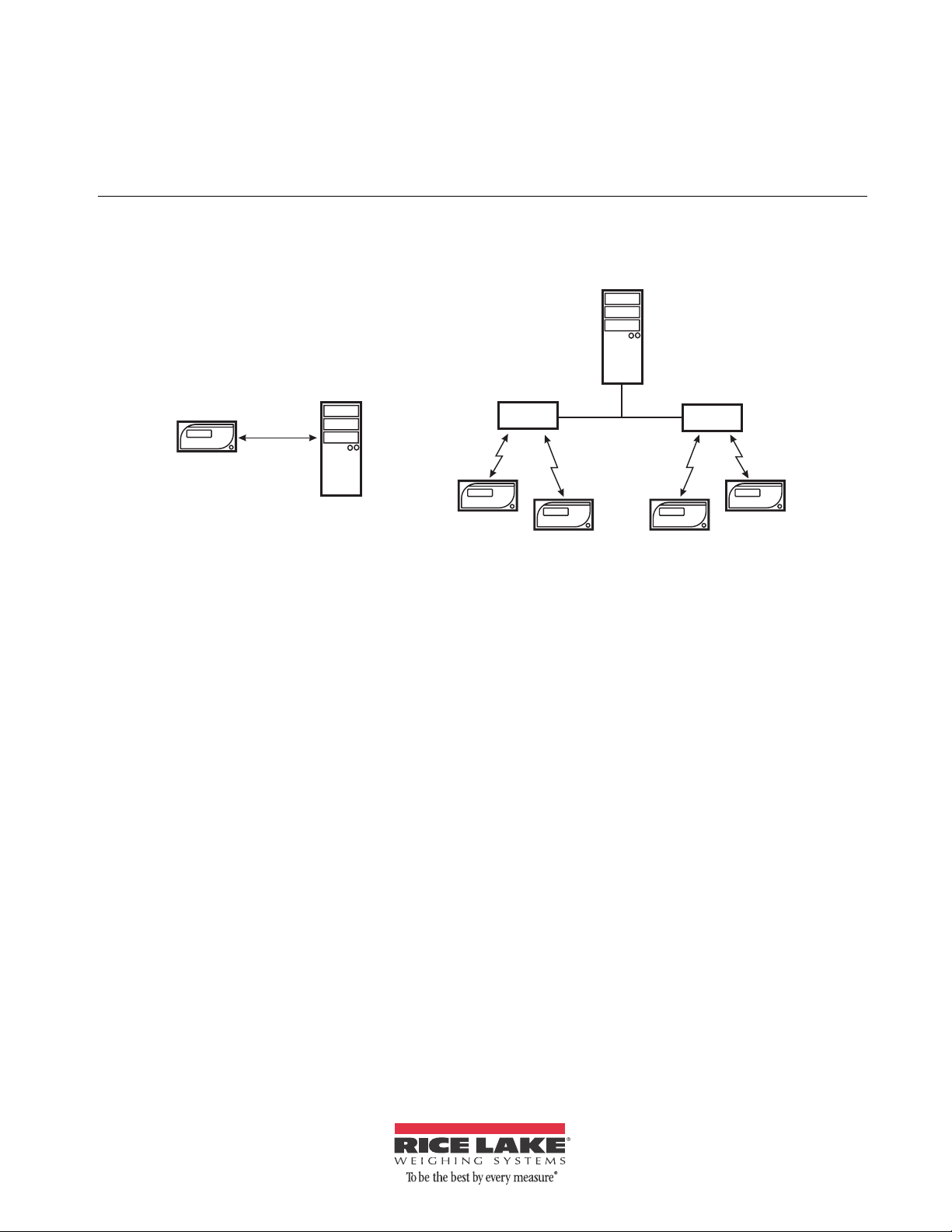
Counterpart
WLAN or
Ethernet
PC
Network
Server
AdHoc connection with
a single Counterpart and PC
Router or
Access Point
Router or
Access Point
Infrastructure connection with multiple Counterparts
Company Network
WeighVault™ Installation Instructions
Option PN 125546
WeighVault allows users to add, edit, and access IDs ove r a Eth ernet or WLAN network connection. WeighVault
surpasses the
data as transactions occur, and provides detailed reports which can be exported to Excel, Word, or PDF.
Counterpart’s 150 ID limitation and eliminates front-panel entry of ID parameters. It also collects
Pre-Installation Checklist
Minimum System Requirements
• 1.0 GHz Intel compatible processor
• 1 GB of RAM
• 850 MB hard drive space (32-bit)
2 GB hard drive space (64-bit)
• Microsoft Windows® XP SP3 (32-bit),
W
indows Vista™ (32-bit or 64-bit) or newer
32-bit or 64-bit Windows operating system
• TCP/IP connections to the
Recommended System Requirements
• 1.0+ GHz Intel compatible processor
• 2 GB of RAM
• 4 GB of hard drive space
• Microsoft Windows® XP SP3 (32-bit),
W
indows Vista™ (32-bit or 64-bit) or newer
32-bit or 64-bit Windows operating system
• TCP/IP connections to the
Figure 1. WeighVault possible connections
Network Requirements
• The PC running the WeighVault service must
have a static IP address
• Known IP address and subnet of the host PC;
if co
SSID and security settings (pass keys and
phrases)
• Network policy must allow passwords of 10
indicator
Other Requirements
charac
• Indicator must be connected to a PC via a
wired Ethernet or wireless network.
• Specific WeighVault settings must be
configured in the indicator
Ethernet/WLAN Connection
The physical connection between the indicator and a
network can be accomplished using:
indicator
• Onboard Ethernet TCP/IP Interface
• Internal WLAN Interface Option, PN 125495
nnecting via WLAN, known network
ters
’s menu.
July 2013 125561
Page 2
Installation
Note
Setting up WLAN Options
NOTE: For detailed instructions, refer to the manuals supplied
with the option kits. Perform the installation at an ESD-safe
workstation.
1. Disconnect the indicator from its power
source.
2. Remove the back cover from the indicator.
3. Remove the option cover plate.
4. Remove the WLAN option card from its ESD
ba
g.
5. If installing WLAN, carefully screw the
included
antenna onto the white RF cable on
the cover plate. In addition, set the WiPt/Xcvr
switch to the Xcvr position, and place both
CFG/LOOP jumpers in the CFG position.
6. Install the 2 plastic standoffs into the two holes
on the indica
tor's CPU board located
approximately 1.5 inches to the left of J5.
7. Carefully align the Ethernet / WLAN option
ard connector with the J14 COMM-OPTION
c
connector on the indicator's CPU board. Press
down to seat the card in the connector and the
two standoffs.
8. If installing WLAN, the antenna is on the
plate. In washdown environments, we
cover
recommend the antenna joint not be exposed to
the environment as the product may become
trapped in the joint. In non-washdown
applications, the joint should be exposed and
positioned to follow the travel of the indicator's
tilt direction.
9. Hardware installation is complete. Do not
install the
indicator's cover until configuration
is complete.
WeighVault service and editor installation
1. Insert the WeighVault DVD (PN 125546).
2. Click
Install WeighVault Service for 32-bit or
64-bit, depending on your system type.
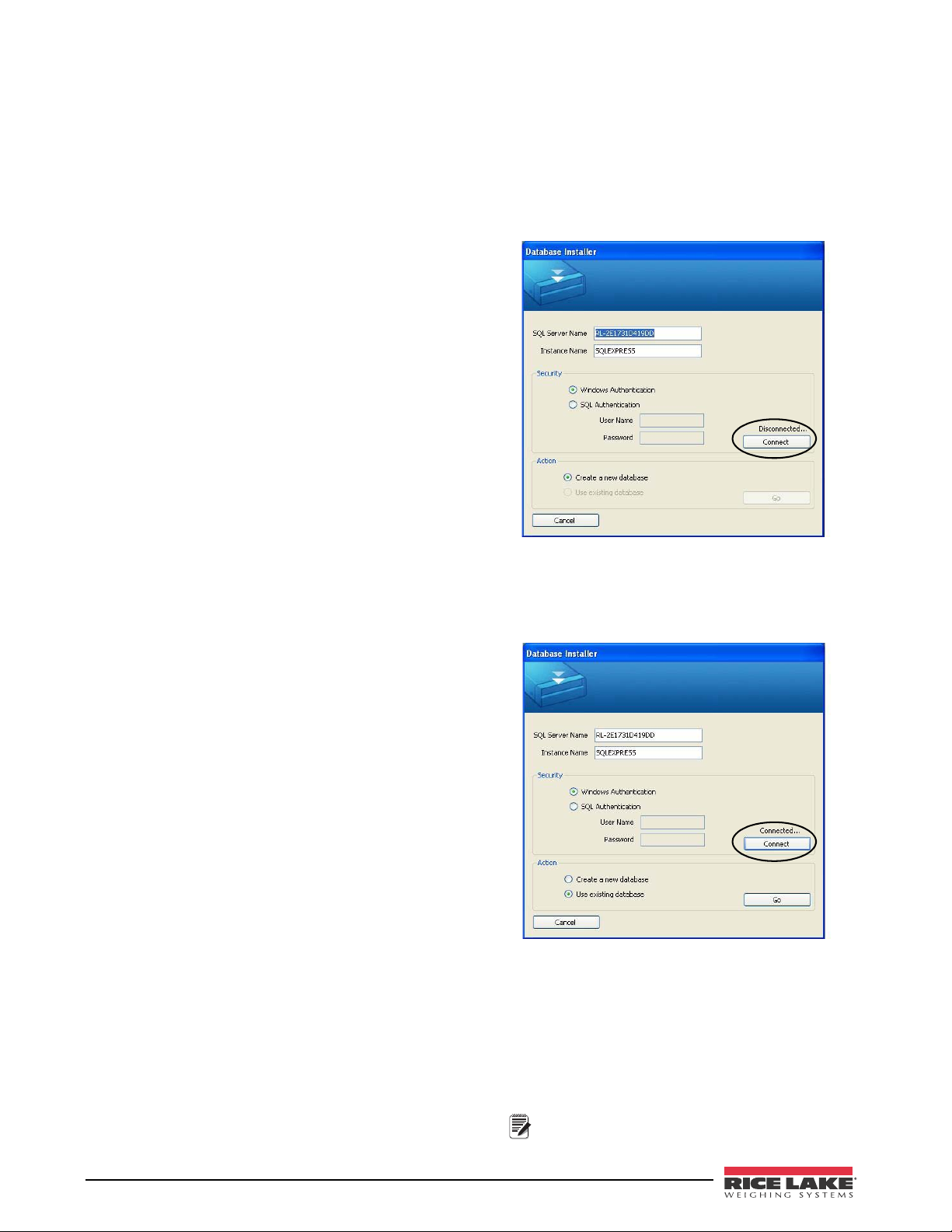
3. Follow the on-screen steps unti
l you reach the
Database Installer shown in Figure 2.
Figure 2. Database Installer screen (disconnected)
4. Click Connect.
5. When the status changes from Disc
Connected, click Go.
onnected to
2 WeighVault Installation Instructions
Figure 3. Database Installer screen (connected)
6. Upon successful installation, click Close.
7. Click
Install WeighVault Editor for 32-bit or 64-bit,
depending on your system.
8. Follow the steps until installation is complete;
then, click
Close.
9. Restart your PC.
Computer must be restarted for the WeighVault
service to load.
Page 3

SCALES FEATUR
PFORMT
VERS
XXXXXXX
ID ACCUM DISPLAYTESTSETUPAUDIT CALIBR
CONFIG
DIGI/O
SERIAL ETHERNET
DHCP
NET MASK
DFLTGTWY
PORT
LC LMSTNM
DNSPRI
REMOTE IP
REMOTE PT
MAC
IP ADDRESS
VAULT
DNSSEC
Configuring the Counterpart
1. From the SETUP menu, navigate to CONFIG » ETHERNET.
2. Configure the ETHERNET menu’s parameters as shown in Table 1.
Figure 4. Counterpart’s ETHERNET menu
IP ADDRESS
NET MASK Sets a subnet mask, if necessary 255.255.255.0 (consult with n
DFLTGTWY Sets the default gateway, if necessary Consult with network administrator
LC LMSTNM LCL name Consult with network administrator
REMOTE IP Remote IP address IP address of the server/computer running WeighVault
REMOTE PT Remote port 5466
Parameter Description Selection
DHCP Dynamic Host Control Protocol OFF (consult with network administrator)
Assigns an IP address to the
Counterpart
Set to an available static IP address
(consult with network administrator)
etwork administrator)
DNSPRI Primary DNS, if necessary Consult with network administrator
DNSSEC Secondary DNS, if necessary Consult with network administrator
PORT Port number Port 10001
MAC MAC address Addres of Ethernet (not changeable)
VAULT Enable WeighVault
Set to ONBOARD to use the
Counterpart’s onboard
Ethernet connection. Set to EXTERNAL to use the WLAN
option card (if installed)
Table 1. ETHERNET menu parameters and selections
3
Page 4

PC or Server configuration
Important
Note
Note
Indicators communicate with the host PC through TCP
Port #5466. In order for this communication to take
place, the indicator's Ethernet or WLAN option card
needs to know the IP address of the host PC. Therefore,
the host will need a static (not dynamic) IP address.
If using a network server, ask your network
administrator for the IP a
ddress of the server, and
confirm the address is static. If using a PC, refer to the
instructions supplied with the PC, or Windows, to help
you set up the computer with a static IP address.
If your PC or network is running a
firewall, it may be necessary to create
an exception for TCP Port 5466.
Configuration WLAN Option Card
The WLAN option card will require specific
configuration to work properly with WeighVault. It can
be configured using a network-based Windows
application called Device Installer, which is provided
on the WeighVault DVD and the CD included with the
option card. However, with the WLAN option card, an
initial configuration is required via RS-232 before
Device Installer can be used.
Configuration of the WLAN option card should
be performed by someone familiar wit
familiar with the network the card is going to attach to. At
minimum, you must know the IP address and subnet of the
host PC, and if connecting via WLAN, the network SSID and
security settings (pass keys and phrases).
More detailed configuration instructions are available on the CD
and in the manuals provided with the option card.
computer networking, and more specifically,
h general
Installer). This address must be on the
same subnet as the address for the host PC
or server .
• The IP Subnet Mask (can be set with
vice Installer).
De
• Network type: AdHoc or Infrastructure.
• Network SSID, or name.
• Channel Number (if AdHoc only).
• All required security parameters (i.e.,
WEP
, WPA, associated pass keys or
phrases).
4. Save the settings.
The card should now be able to connect to the network.
ake note of the WLANACT LED on the card. If it is
T
on, or blinking, you do NOT have a connection. If it is
off, the connection is successful. You may now use
Device Installer to perform the remaining settings.
Ethernet WLAN Option Card Configuration using Device Installer
1. Start the Device Installer program.
Upon opening, the program will search the
network for any Lantronix WLAN optio
n
cards available.
2. Once it finds your option card, you may select
and perform the following configuration
it
using the Web Browser Configuration Tool:
Please refer to the manual included with the
option card, along with the complete Lantronix
User Guide provided on the CD,
instructions for configuration of the option card.
for detailed
Installing Device Installer on your PC
1. Insert the CD included with the WLAN option
card and select Install Device Installer. Follow the
onscreen instructions.
Initial Configuration of WLAN Option Card via RS-232
The first step required for using the WLAN option card
is to configure its Network Type, IP address and
subnet, and the SSID and network security settings.
Because the card can not connect to the network until
these settings are made, it must first be configured
through an RS-232 connection and a simple terminal
program, such as Hyperterminal, Procomm, or Putty.
1. Connect a PC's RS-232 port to J2 on the
WLAN o
ption card. If the PC is equipped with
a 9-pin connection, connect pin 3 to J2-TX, pin
2 to J2-RX, and pin 5 to J2-Gnd.
2. Set both CFG/LOOP jumpers to CFG.
3. Using the instructions co
ntained in the manual
supplied with the WLAN Option card, set the
following parameters:
• Set the Network Mode to Wireless Only.
• The IP address you want to assign to the
Option Card (can
be set with Device
• If using Ethernet, you will need to assign the IP
address and subnet first.
• Make the following settings to Channel 1
(Chann
el 2 if WLAN):
• Connect Mode to “Connect With Any
Charac
ter.”
• Remote Port to “5466.”
• Remote Host to the IP address of the host
PC or S
erver that is running the
We ighVault service.
• All other settings should remain default, aside
the initial WLAN settings set above.
from
3. Click
Settings.
Configuring an External RS-232 to Ethernet or WLAN converter
OK on every page, then click Apply
Rice Lake Weighing System does not directly support
third-party converters. If used, the converter must be
set up using the manufacturer's instructions. You will
need to match the RS-232 settings, as well as set the
unit up to initiate a TCP connection to TCP Port 5466
on the WeighVault host any time data is presented by
Counterpart on the RS-232 side.
the
4 WeighVault Installation Instructions
Page 5

After a short period of LAN inactivity, the host will
terminate the connection, so the converter will have to
reinitiate the connection anytime the
Counterpart
requests an ID, or transmits weighment data.
Using WeighVault
The Counterpart WeighVault system should now be
ready to use.
1. Start the WeighVault editor and add an ID to
the database.
2. On the Counterpart, attempt to recall that ID
by pressing the ID key, entering the ID
number, and pressing
Enter.
3. The Counterpart will scroll a message stating
it is loading the ID.
4. If the connection to WeighVault is successful,
the message will change to Loading ID from
PC.
If the connection is not successful, it will
respond with No ID, or it will load that ID from
its local memory, if programmed. Try to
establish the connection again.
If the ID continues to fail to load, verify all
settings in the
Counterpart, option card, and
host PC. Also verify a firewall in the system is
not blocking access to port 5466 of the host,
and that all wiring is correct.
5
 Loading...