

Page 1
INST ALLA TION AND
SYSTEM GUIDELINES
43918
Page 2

CONTENTS
Vessel W eighing System Design......................................................... Section 1
Bulk Material Weighing Systems • Load Introduction Principles • Maximizing System Accuracy •
Selecting Number of Supports & Load Cell Capacity • Choosing the Correct Load Cell • Calibrating
Thermal Expansion of Vessels & Stay Rods • Calculating T ank V olumes • Densities of Common Materials
• Load Cell Bolt Torque Values • Wind and Seismic Effects on Vessel Stability
Weigh Modules ................................................................................ Section 2
Single-End Beam Load Cell Modules • Double-End Beam Load Cell Modules • Compression Canister
Load Cell Modules • S-Beam Load Cell Modules • Mounting Assemblies and Compatible Load Cells
Vessel Attachments .......................................................................... Section 3
Attaching Piping to Weigh Vessels • Piping Guidelines • Vessel Restraint Systems • Low-Accuracy
Systems: Partial Mounting on Flexures
Installation & Service Tips ............................................................... Section 4
Before Installing • Determining Microvolts per Graduation • Load Cell Mounting Hardware Safety
Guidelines • Load Cell T rimming • Load Cell Troubleshooting • Selecting Replacement Load Cells •
Load Cell Wiring Guide • Calibrating Vessel W eighing Systems
Glossary.......................................................................................... Section G
!
All vessel weighing system installations should be planned by a qualified structural engineer.
Warning
This manual is intended to serve only as a general guide to planning, installation, and servicing of these
systems; no attempt has been made to provide a comprehensive study of all possible system configurations.
Copyright © 1997 Rice Lake Weighing Systems. All rights reserved. Printed in the United States of America.
Specifications of products described in this handbook are subject to change without notice.
December 1997
Page 3

SYSTEM DESIGN
VESSEL WEIGHING SYSTEM DESIGN
Bulk Material Weighing Systems ...................................................................................1-2
Custody T ransfer................................................................................................................................................................ 1-2
Material Proportioning ...................................................................................................................................................... 1-2
Loss in Weight ................................................................................................................................................................... 1-2
Common Hopper Scale Arrangements .............................................................................................................................. 1-3
Load Introduction Principles......................................................................................... 1-6
The Ideal... ......................................................................................................................................................................... 1-6
Angular Loading ................................................................................................................................................................ 1-6
Eccentric Loading.............................................................................................................................................................. 1-6
Side Loading ...................................................................................................................................................................... 1-7
Twisting Loads ................................................................................................................................................................... 1-7
Contents
Maximizing System Accuracy ........................................................................................ 1-8
Environmental................................................................................................................................................................... 1-8
Load Cell and Mount.......................................................................................................................................................... 1-8
Mechanical/Structural ....................................................................................................................................................... 1-8
Calibration ......................................................................................................................................................................... 1-8
Operational Considerations ............................................................................................................................................... 1-8
Selecting Number of Supports & Load Cell Capacity....................................................... 1-9
Number of Supports .......................................................................................................................................................... 1-9
Load Cell Capacity ............................................................................................................................................................. 1-9
Choosing the Correct Load Cell ................................................................................... 1-10
Environmentally Protected...............................................................................................................................................1-10
Hermetically Sealed ..........................................................................................................................................................1-10
International Protection (IP) Rating Guide ......................................................................................................................1-11
Calculating Thermal Expansion of Vessels & Stay Rods ................................................ 1-12
Stay Rod Expansion/Contraction.................................................................................................................................................1-12
Vessel Expansion/Contraction .....................................................................................................................................................1-12
Calculating Tank Volumes........................................................................................... 1-14
Formulas for Various Tank Shapes and Sections ..............................................................................................................1-14
Calculation Examples .......................................................................................................................................................1-17
Densities of Common Materials ................................................................................... 1-19
Load Cell Bolt Torque Values....................................................................................... 1-23
Wind and Seismic Effects on Vessel Stability................................................................ 1-24
1-1
Page 4
SYSTEM DESIGN
a
a
a
a
a
a
a
a
a
a
a
a
a
a
aa
a
aa
aaa
a
a
a
a
a
a
a
a
a
a
a
a
a
a
a
a
a
a
a
a
a
a
a
a
a
a
a
a
a
a
a
a
a
a
a
aa
a
aa
aaa
a
a
a
a
a
a
a
aa
a
a
aa
a
a
a
a
a
aa
aa
a
a
a
a
aa
a
a
a
a
a
a
a
a
a
a
a
a
a
a
a
aa
a
a
a
a
a
a
a
a
a
a
a
a
a
a
a
a
a
a
a
a
a
a
a
a
a
a
aa
a
a
a
a
a
a
a
a
a
a
a
a
a
a
a
a
a
a
a
a
a
a
a
a
a
a
a
a
aa
a
aa
a
a
a
a
a
aaa
a
aa
a
a
a
a
aa
a
a
a
a
a
a
a
a
a
a
a
a
a
aa
aa
a
a
aa
a
a
a
a
a
a
a
a
a
aa
a
a
aa
a
a
aaa
a
a
a
a
a
a
a
a
a
a
a
a
a
a
a
a
a
a
a
a
a
a
a
a
a
a
a
a
a
a
a
a
a
a
a
a
a
a
a
a
a
a
a
a
a
a
a
a
a
a
a
a
a
a
a
a
a
a
a
a
a
a
a
a
a
a
a
a
a
a
a
a
aa
a
a
a
a
a
a
a
aa
a
a
a
a
a
a
a
a
a
aa
a
a
a
a
a
a
a
a
a
a
a
a
a
a
a
a
a
a
a
a
aaa
a
a
a
a
a
Bulk Material W eighing Systems
Bulk materials are weighed for various reasons. Although this discussion focuses on the weighing of bulk solids, many of the principles
are equally applicable to the weighing of bulk liquids. For the sake of convenience, we have classified bulk material weighing into three
general types:
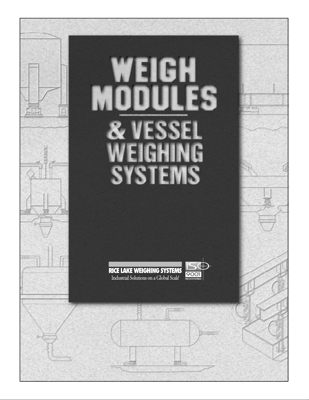
Custody Transfer
Figure 1-1
Weighing bulk material on a truck scale is a typical example of
custody transfer weighing where material is being traded for
dollars. The filled truck is weighed and the known tare weight of
the truck is subtracted to determine the net weight of product. This
may be done for invoicing or inventory-control purposes. Typically, achieving a predetermined weight is not important in this
situation. What is important is knowing how much material
entered or left the facility.
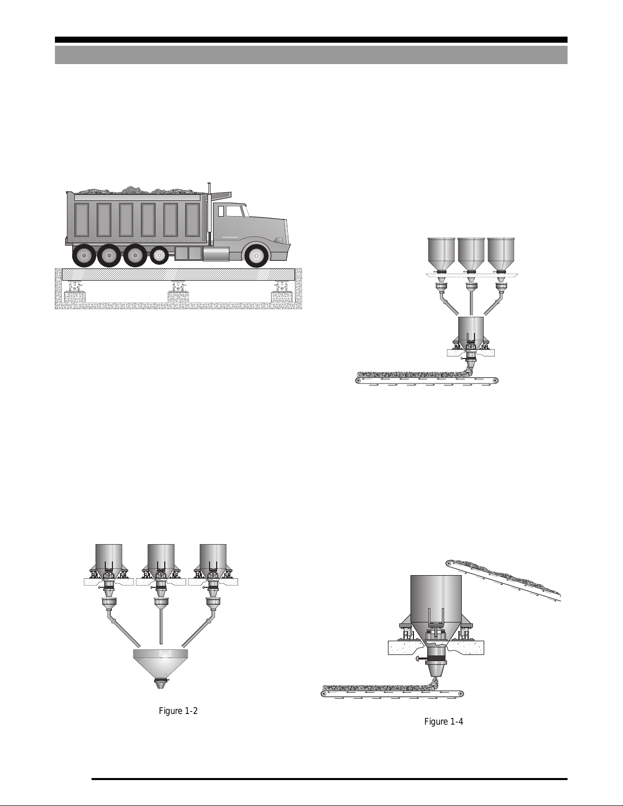
Material Proportioning
Figure 1-2 shows various ingredients being weighed on separate
scales, then mixed. Each scale must be accurate, or there could
be a detrimental effect on the proportions of each ingredient in
the finished product.
Figure 1-3 shows several materials being mixed to a given recipe
and batched one at a time into a single weigh hopper. As all
ingredients are weighed in the same weigh hopper, the weighing
system must be linear to achieve correct proportioning. It does not
need to be calibrated accurately if the final net weight of product
is not critical.
Loss in Weight
Figure 1-4 shows a situation where the weigh hopper is first topped
up and when the filling process stops, the material is fed out at a
controlled rate. The total amount of material supplied to the
process may be important, but the rate at which product is fed into
the batching process from the weigh hopper is usually more
important.
Bulk Material Weighing Systems
Figure 1-3
Figure 1-2
Figure 1-4
1-2
Page 5
Bulk Material Weighing Systems
a
a
a
a
a
a
a
aa
a
aa
aaa
a
a
a
a
a
a
a
a
a
a
a
a
a
a
a
a
a
a
a
a
a
a
a
a
a
a
a
a
aa
a
aa
aaa
a
a
a
a
a
a
a
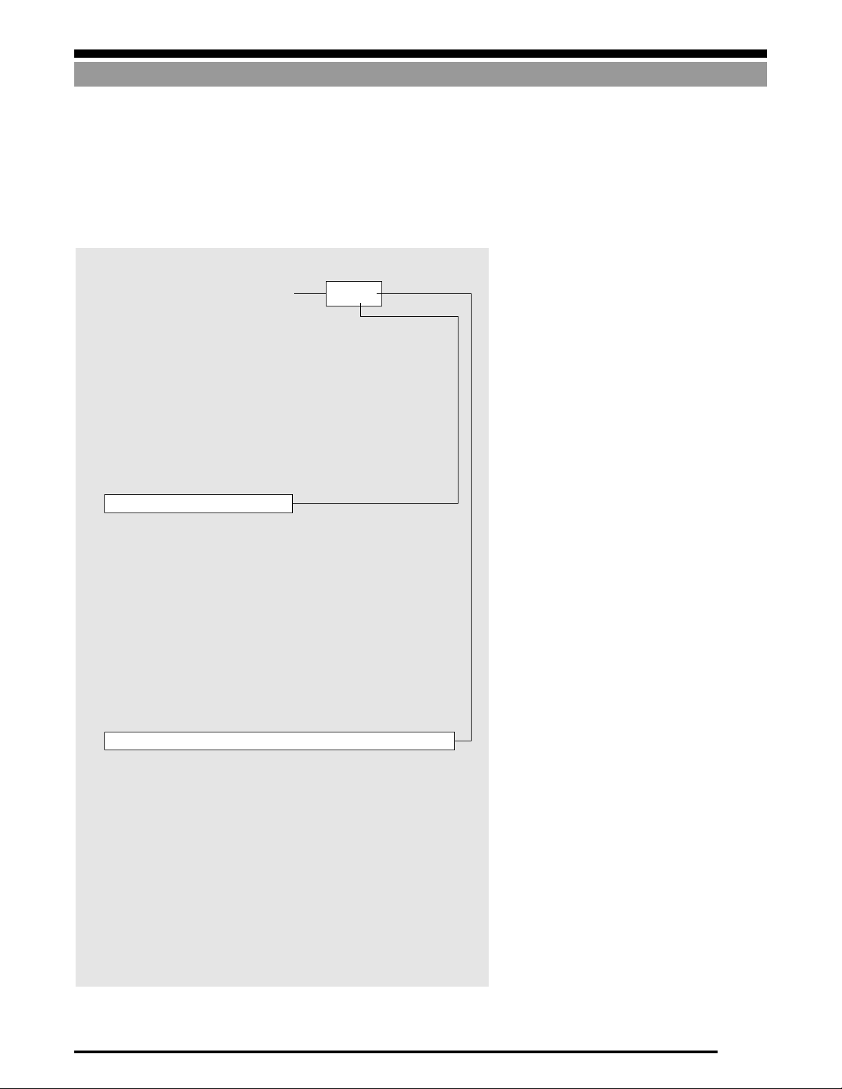
Common Hopper Scale Arrangements
SYSTEM DESIGN
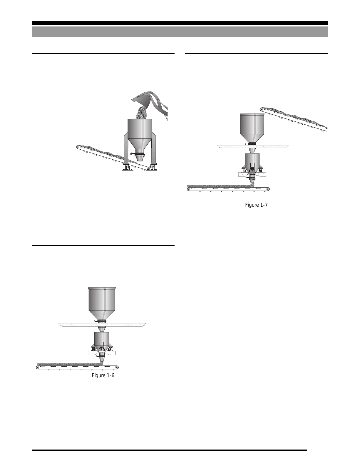
A. One of the simplest hopper weighing systems is illustrated
below in Figure 1-5. The weigh hopper may be filled using a
feed conveyor, front-end loader, auger, etc., and the material
may be removed from the hopper using a discharge conveyor.
Figure 1-5
Advantages of this system are:
• Low cost compared to other systems.
• Low overall height.
Disadvantages of this system are:
• Slow fill and discharge (low throughput).
• Difficult to achieve an accurate prescribed weight because
of inconsistency in input material flow.
B. Figure 1-6 below illustrates a weigh hopper positioned
directly under the storage silo.
Advantages of this system are:
C. A conveyor-fed system can be improved by adding an upper
surge hopper as shown in Figure 1-7. The surge hopper allows
the conveyor to be run continuously and isolates the weigh
hopper from the sometimes erratic flow of material from the
conveyor.
Figure 1-7
Advantages of this system are:
• Weigh hopper isolated from the feed conveyor.
• The input conveyor can run continuously.
• Surge hopper serves as a buffer to smooth out demand.
• 2-speed fill is possible.
• Faster fill and higher throughput possible.
Disadvantages of this system are:
• Higher overall height.
• Higher cost.
• More complex controls and mechanical arrangement.
Figure 1-6
• The weigh hopper is gravity-fed, simplifying the feed process
and providing a more uniform flow.
• Faster fill cycle and hence greater throughput.
• 2-speed fill may be used for greater target accuracy.
Disadvantages of this system are:
• Higher overall height.
• Material must be conveyed higher to storage silo.
1-3
Page 6
SYSTEM DESIGN
a
a
a
a
a
a
a
a
a
a
a
a
a
a
a
a
a
a
a
a
a
aa
a
aa
aaa
a
a
a
a
a
a
a
a
a
a
a
a
a
a
a
a
a
a
a
a
a
aa
a
aa
aaa
a
a
a
a
a
a
a
a
a
a
a
a
a
a
aa
a
aa
aaa
a
a
a
a
a
a
a
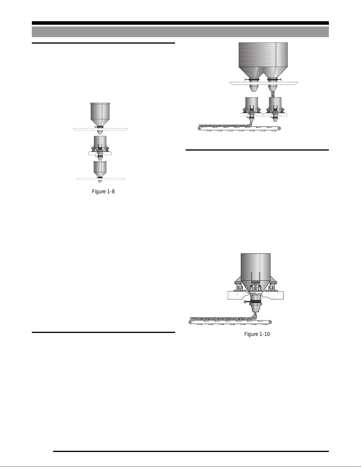
D. This arrangement is similar to Example C, however, a lower
surge hopper has been added to speed up the discharge cycle.
This system, shown in Figure 1-8, is typically used in multidraft grain loadout systems where multiple drafts are required to fill a rail car or barge. The weight of each draft can
be accumulated and the target weight of the final draft
adjusted to achieve the desired car net load.
Figure 1-8
Advantages of this system are:
• Weigh hopper isolated from feed conveyor.
• Surge hopper serves as a buffer to smooth out demand.
• 2-speed fill is possible.
• Faster fill, discharge, and throughput possible.
Bulk Material Weighing Systems
Figure 1-9
F. Figure 1-10 illustrates a loss in weight system. This is used
where a process needs a batch of material (not more than the
capacity of the weigh hopper), but that material needs to be
fed to the process at a controlled rate.
The process starts by filling the hopper with at least enough
material for the upcoming process. The fill is then stopped
and the discharge commences. The rate at which the discharge takes place is controlled by monitoring the “loss in
weight” of the hopper and then modulating the discharge
rates to maintain the desired flow rate. The discharge may be
ended at the completion of the process step, or when a specific
amount of material has been discharged.
Disadvantages of this system are:
• Higher overall height.
• Higher cost.
• More complex controls and mechanical arrangement.
The systems described up to this point deliver a single material in
pulses rather than from a continuous flow. They may be used for
in-plant process weighing or custody transfer. Figures 1-9 and 110, described below, provide a continuous material flow and are
more often used for process weighing.
E. Figure 1-9 illustrates a single storage silo with two weigh
hoppers suspended underneath. This arrangement can be
used to provide material continuously to a process. As one
hopper is emptying, the other can be filling If the system is
sized correctly, there is no interruption to the material flow
on the discharge belt.
Advantages of this system are:
• Continuous material flow.
• High throughput possible.
Disadvantages of this system are:
• Higher overall height.
• Higher cost than pulse discharge systems.
• More complex controls and mechanical arrangement.
Advantages of this system are:
• Gives the ability to supply material at a constant rate
Disadvantages of this system are:
• Complex controls and mechanical arrangement
• Higher cost than pulse discharge systems.
Figure 1-10
1-4
Page 7
Bulk Material Weighing Systems
a
a
a
a
a
a
a
a
a
a
a
a
a
a
aa
a
aa
aaa
a
a
a
a
a
a
a
a
a
a
a
a
a
a
aa
a
aa
aaa
a
a
a
a
a
a
a
a
a
a
a
a
a
a
a
a
a
a
a
a
a
a
a
a
a
a
a
a
a
a
a
SYSTEM DESIGN
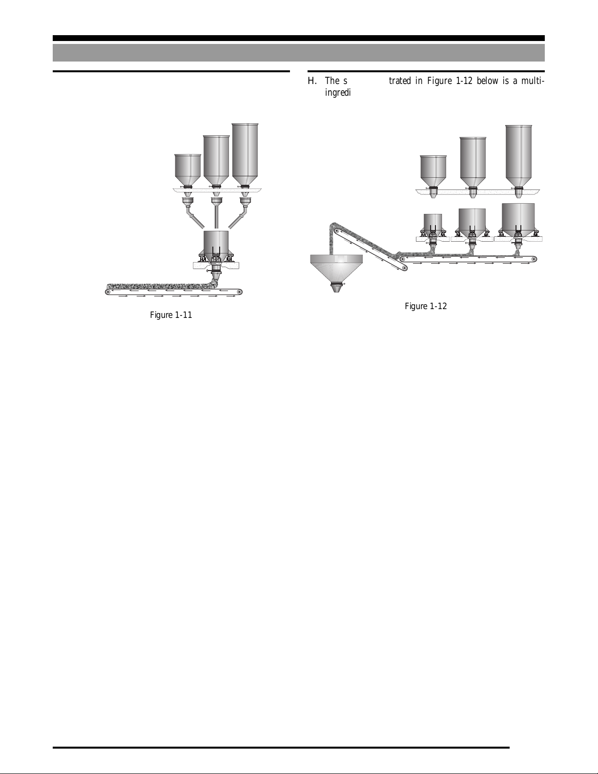
G. Figure 1-11 illustrates a multiple-ingredient batching sys-
tem where all the ingredients are weighed one at a time in a
single weigh hopper.
Figure 1-11
Advantages of this system are:
• Lower cost than multiple-weigh hoppers
• Scale calibration may not be critical, as all ingredients are
weighed in a single scale, assuring correct proportions.
Disadvantages of this system are:
• The accuracy of minor ingredients may suffer where the scale
capacity is large compared to the weight of ingredient.
• System is somewhat slow because each material must be
batched in one at a time, and the cycle cannot repeat until the
weigh hopper has been discharged.
H. The system illustrated in Figure 1-12 below is a multi-
ingredient batching system which has a separate weigh hopper for each ingredient.
Figure 1-12
Advantages of this system are:
• Weigh hopper capacity can be sized appropriately for each
material so that each weighment is close to the scale capacity,
providing greater accuracy.
• Faster throughput, since all materials can be weighed and
discharged simultaneously.
Disadvantages of this system are:
• Higher cost.
• Each scale must be accurate to ensure correct proportioning.
Note: We recommend that you do not attempt to weigh a batch of
material which is less than 20 scale divisions since the accuracy
will be questionable.
For example, if a hopper scale has a .5 lb division size, we recommend that you not weigh less than a 10-lb batch on that scale. It’s
better to weigh minor ingredients accurately on a scale suited to
the purpose, and add those ingredients to the batch by hand. For
example, if making raisin oatmeal cookies, it may not be too much
of a problem to batch-weigh the raisins along with the oatmeal.
However, it may be prudent to weigh the salt on a more sensitive
bench scale and hand-add it to the hopper at completion of the
weigh cycle.
1-5
Page 8
SYSTEM DESIGN
Load Introduction Principles
Load Introduction Principles
A clear understanding of the exact manner in which a load must be placed on a load cell will assist you in both designing a vessel that is
to be equipped with load cells, and in choosing the correct type of load cells and mounts for your application.
The Ideal...
Load cell specifications are derived under laboratory conditions,
where load is applied to the cell under near-perfect conditions. The
performance of load cells in an actual process weighing application
can be greatly degraded if care is not taken in the means by which
the load is applied to the cell.
If the direction of the force is constant, calibration will compensate
for this and the scale will weigh accurately. However, if the angle
changes as the force is applied, it will cause nonlinearity and if
there is friction in the mechanical system, hysteresis will also be
present. Angular loads can be caused by mounts that are out of
level, a nonrigid foundation, thermal expansion/contraction, structure deflection under load, and the unavoidable deflection of the
load cell itself.
C
L
C
L
Figure 1-14
Figure 1-13
Figure 1-13 shows a typical mounting arrangement for a singleended beam. The fixed end is fastened to a “rigid” foundation, while
the free end is cantilevered to allow downward deflection as load
(F) is applied. Under ideal conditions, the mounting surface would
be flat, horizontal and perfectly rigid. The load F would be introduced vertically with minimal extraneous forces applied, and the
load cell would be totally insensitive to all forces other than
precisely vertical ones.
However, in the real world, load cell mounting and loading conditions are far from ideal. Incorrect loading is by far the most
common cause of accuracy problems encountered by service
technicians. Understanding the following common load introduction problems will prevent loading errors in your vessel weighing
application.
Though the discussion is confined to single-ended beams, many of
the principles apply equally to other load cell types.
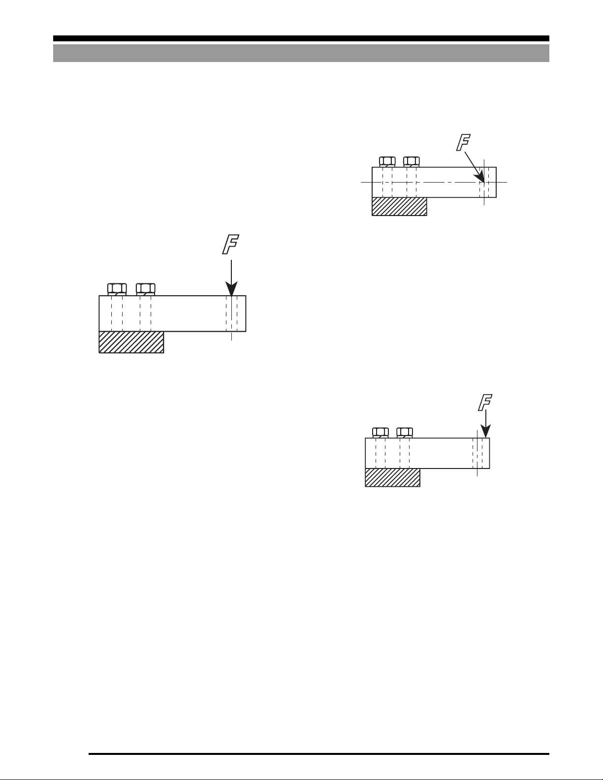
Angular Loading
This is a condition where the load F is introduced through the
loading hole, but at an angle to its center line. This angular force
can be broken up into its vertical component along the loading
hole center line which the cell will register and its horizontal
component at 90° from the center line. This horizontal component
is a side force to which, ideally, the load cell would be totally
insensitive. For example, if force F is inclined to the load hole
center line at an angle of 5°, then the force registered by the cell is
reduced by .4% while a side force of .01F is also applied.
Eccentric Loading
This is a condition where the force F is applied vertically to the cell,
but its line of action is shifted away from the vertical line through
the loading hole. This is not a detrimental condition if the force is
applied consistently at the same point, since calibration will
compensate for this effect. However, if the point of application
moves horizontally as the scale is loaded, it will cause nonlinearity
and possibly hysteresis. Eccentric loads may be caused by poorlydesigned mounting arrangements and thermal expansion/contraction of the scale.
Figure 1-15
1-6
Page 9
Load Introduction Principles
SYSTEM DESIGN
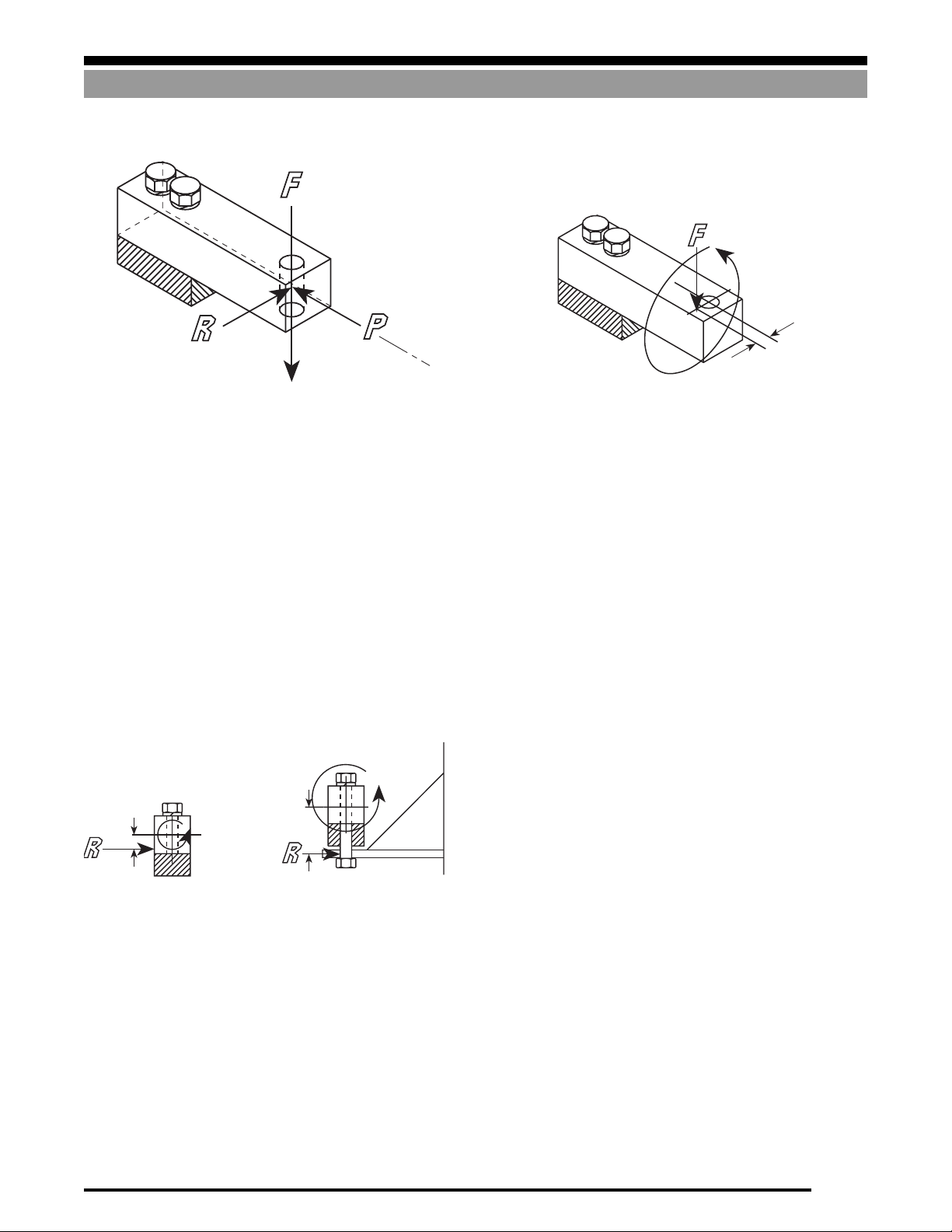
Side Loading
Figure 1-18 illustrates a torque of magnitude Fy exerted as the
result of the load F being applied at a distance y from the loading
hole center line.
Figure 1-16
This is a condition where the vertical force F (which you are trying
to measure) is accompanied by a side force R applied at 90° to F.
This force can be constant, but more typically is a force that varies
over time and hence affects the linearity and possibly the hysteresis
of the scale. The ideal load cell would be totally insensitive to side
loads. However, in practice these extraneous forces do affect the
Mounts which are out of level, thermal expansion/contraction,
structure deflection under load and dynamic side forces (caused by
rotating mixers, etc.) all cause twisting of the load cell. Since these
forces tend to vary in magnitude as a function of time, temperature
and/or load, the effects are not predictable, and will degrade system
accuracy.
output of the cell and two seemingly identical cells can react
differently to the same side load. A related condition is the END
FORCE, P, which is similar to a side force, except that it acts on the
end face of the cell. Side forces are the result, typically, of thermal
expansion/contraction, mounts which are not level, and vessel
dynamics (caused by mixers, etc.).
T
y
Figure 1-18
Twisting Loads
T
T
C
h
L
(a) (b)
Figure 1-17
Typically, a side force does not act exactly at the neutral axis and
hence produces a torque or twisting effect in addition to the side
force. A load cell can be subjected to a torque (T) in a number of
ways. Figure 1-17 (a) illustrates a condition where the line of action
of a side force is moved away from the neutral axis by a distance h
resulting in a torque of Rh. Figure 1-17 (b) illustrates a situation
where the load is hung from the cell using a bolt. Any side force
applied by this arrangement has a much larger twisting effect on
the cell because of the increased distance h1 to the neutral axis.
h
1
1-7
Page 10

SYSTEM DESIGN
Design Elements
Maximizing System Accuracy
High-accuracy systems are generally considered to have system errors of ±.25% or less; lower accuracy systems will have system errors
of ±.50% or greater. Most weight indicators typically have an error of ±.01%, hence, the main source of error will be the load cells and,
more importantly, the mechanical arrangement of the scale itself. In vessel weighing, each installation is unique in terms of the
mechanical arrangement, site conditions and environmental factors. Therefore, it is impossible to be specific in this publication about
the system accuracy that can be achieved. The first requirement is to determine what the customer’s accuracy expectations/requirements
are, then design the system accordingly. Grouped under various subheadings below are various recommendations that contribute to high
accuracy. It will not be possible to comply with all these recommendations; however, they should be kept in mind when designing a system.
Environmental
■ Install the vessel in a controlled environment where seasonal
temperature fluctuations are minimized. If this is not feasible, use load cells with temperature compensation specifications that will allow satisfactory performance over the expected temperature range.
■ Use a metal shield to protect the load cells from radiant heat
sources. Use an insulating pad between the vessel and load cell
mount if heat is being conducted.
■ If thermal expansion/contraction of the vessel is expected,
choose a mount which will allow unhindered lateral movement. If stay rods are required, position them so that thermally-induced movement is minimized. See Vessel Restraint
Systems in Section 3 for more information.
■ Place the vessel indoors, if possible, where it will be protected
from wind and drafts.
■ Do not place the vessel in an environment where its support
structure is subject to vibration. Ensure that vibrations are
not transmitted via attached piping or stay rods.
■ Select load cells and mounts that will give the degree of
corrosion protection required.
■ Use load cells that have the degree of environmental protection required for the application. For example, avoid possible
drifting problems with standard load cells in washdown applications by specifying hermetically-sealed cells.
Load Cell and Mount
■ Choose load cells whose accuracy is consistent with the
desired system accuracy.
■ Do not grossly oversize the load cells; see Load Cell Capacity
on page 1-9. Best accuracy will be achieved when weighing
loads close to the vessel capacity. As a general rule, do not
attempt to weigh a load of less than 20 graduations.
■ If it is not possible to trim the corners, use load cells with
matched outputs, particularly if the vessel is not symmetrical
and/or the material is not self-leveling. Otherwise, use a
pretrimmed junction box.
■ Support the vessel entirely on load cells; do not use dummy
cells or flexures that would hinder a good calibration. See
Partial Mounting on Flexures on page 3-11.
■ Use proven load cell mounts that will provide optimal loading
conditions.
■ Orient the mounts as recommended in the installation manual.
Mechanical/Structural
■ Support the load cell mounts on a rigid structure; this will
ensure a high natural frequency and reduce the amount of
bounce and instability. All support points must be equally
rigid to avoid tipping of the vessel as load is applied. Minimize
interaction between adjacent weigh vessels mounted on the
same structure. Vehicular traffic must not cause deflection of
the vessel’s support structure.
■ Ladders, pipes and check rods, etc. should not be allowed to
shunt the weight that should rest on the load cells.
■ Where piping or conduit must be attached to the vessel, use
the smallest diameter acceptable for the application. Use the
longest unsupported horizontal length of pipe possible to
connect to the vessel.
■ Use an indicator that is EMI/RFI protected. Provide grounding and transient protection in accordance with the
manufacturer’s recommendations. In general, take measures
to reduce electrical interference.
■ Use a good-quality junction box which remains stable with
changing temperatures. Look for a junction board which has
a solder mask at a minimum and which preferably is
conformally coated also. Ensure that the enclosure is suited
to the environment.
Calibration
■ Design in a convenient means of hanging weight from the
corners of the vessel to trim the load cell outputs and for
calibration. Use weights as described above, or known weight
of material to perform the calibration. See Calibrating Vessel
Weighing Systems in Section 4.
Operational Considerations
■ Maintain an even and consistent flow of material.
■ Avoid simultaneous fill/discharge of weigh vessel.
■ Slow down the filling cycle as much as possible and/or use a
2-speed fill cycle.
■ Reduce to a minimum the amount of “in flight” material.
■ Use preact learning to predict the optimum cutoff point based
on past performance.
■ Use Auto Jog to top off contents after fill.
■ If possible, switch off any vibrating or mixing equipment
while the weight is being determined.
■ Reduce to a minimum the surging of liquids while a weight
reading is being taken.
1-8
Page 11

Design Elements
VESSEL WEIGHING SYSTEMS
Selecting Number of Supports & Load Cell Capacity
Number of Supports
The number of supports to be recommended is dependent on the
geometry, gross weight, structural strength and stability of the
vessel. The number of supports chosen for a vessel obviously
influences the capacity of the load cells required. In general, no
more than eight supports should be used. It becomes more difficult
to get even weight distribution on all supports as the number
increases beyond three. Below is a look at a number of examples.
Suspended Vessels
These vessels are very often suspended from an existing structure
which will sometimes dictate how many supports will be used. In
general, one or more supports may be used. Using three supports
or fewer has the advantage of not requiring adjustment of
the length of the support linkages to distribute the load
equally between all supports (assuming the cells are arranged
symmetrically on the vessel).
Upright cylindrical vessels in compression
The most convenient method of mounting is with three supports
arranged at 120° degree intervals. Correct weight distribution is
inherent to 3-point support and is preferred whenever possible.
With tall slender vessels or vessels subject to fluid sloshing, wind
or seismic loads, stability against tipping becomes a consideration.
In these situations, four or more supports should be considered.
See Appendix section on wind and seismic effects.
Square, rectangular or horizontal cylindrical
vessels mounted in compression
Because of geometry, it is usually most convenient to mount these
vessels on four supports, close to each corner. Higher capacities
may, of course, require more than four.
Load Cell Capacity
It is vital to the performance of a weighing system to select load
cells of the correct capacity. Here are some guidelines:
■ All load cells selected must be of the same capacity.
■ Estimate the vessel dead weight, including all piping, pumps,
■ Add the maximum live weight of product to be weighed to the
■ Divide the gross weight by the number of legs or support
■ Select a load cell with a capacity somewhat greater than the
A good rule of thumb is to select a load cell with a capacity 50 –
100% in excess of the calculated nominal load per cell. Once the
load cell capacity has been determined, check that the live weight
signal is adequate for the instrumentation selected; see Section 4
for information on how to determine the microvolt-per-graduation for your system. This is particularly important when the ratio
of dead weight to live weight is high.
■ Additional factors to consider:
■ See page 2-22 for compatibility information on mounts and
agitators, insulation and vessel heating fluids.
dead weight. This is the gross weight of the vessel and
contents.
points. This is the nominal weight which will be carried by
each load cell.
nominal weight. The following should be considered when
determining how much greater the load cell capacity should
be:
1. Is your dead weight accurate?
2. Will the load be evenly distributed on all cells?
3. Is the vessel fitted with an agitator or subjected to shock
loading?
4. Is it possible the vessel will be overfilled, exceeding your
live weight value?
5. Will the vessel be subjected to wind or seismic loading?
For more information, see Wind and Seismic Effects on
Vessel Stability.
Load Cell Construction Material — In a corrosive environment, stainless steel outperforms nickel-plated alloy steel.
Load Cell Protection — The ultimate degree of protection
can be achieved with hermetically-sealed load cells which
ensure the integrity of the strain gauge section of the cell in
corrosive or washdown applications.
Cable Length — Check that the standard cable length will
be adequate for your installation. Longer cable lengths are
available on special order.
load cells by capacity. Capacity requirements may limit
practical applications of many models.
1-9
Page 12
SYSTEM DESIGN
Choosing the Correct Load Cell
Misuse of any product can cause major cost and safety problems;
load cells are no exception. Unfortunately, the load cell protection
rating systems used in the industry today are inadequate in some
ways. That’s why Rice Lake Weighing Systems, with years of load
cell experience, has developed its own rating system for load cells.
Our system categorizes load cells in two major groups: hermetically-sealed (HS), and environmentally-protected (EP). Hermetically-sealed cells are then further characterized by IP (International Protection) numbers. We feel this system effectively matches
load cell to application for optimal results.
To choose the proper load cell protection qualities, a fundamental
understanding of the differences between “environmentally-protected” and “hermetically-sealed” load cells is necessary. The
inappropriate use of environmentally-protected load cells in harsh
conditions is a prescription for load cell failure. Because of the
extra manufacturing steps, hermetically-sealed load cells cost
more than environmentally-protected versions. Despite the higher
initial cost, hermetically-sealed load cells may be the best longterm choice for harsh chemical, washdown, and unprotected
outdoor applications.
Environmentally Protected
Environmentally-protected load cells are designed for “normal”
environmental factors encountered in indoor or protected outdoor
weighing applications. By far the most popular type, these load
cells may employ strategies like potting, rubber booting, or redundant sealing to afford some protection from moisture infiltration.
Potted load cells utilize one of several types of industrial potting
materials. The liquid potting material fills the strain gauge cavity
then gels, completely covering the strain gauge and wiring surfaces. While this may significantly diminish the chance of moisture contamination, it does not guarantee extended waterproof
performance, nor does it withstand corrosive attack.
A second method of protection uses an adhesive foam-backed plate.
This protection affords some moisture and foreign object protection, but less than potted cells. In many cases, manufacturers will
use a caulking material to seal the plate to decrease the potential
for cavity contamination. A common approach among manufacturers to further decrease the entry of moisture to the strain gauge
combines both a potted cavity and a foam-backed plate, in a process
called redundant sealing.
Yet another strain gauge cavity protection strategy is the rubber
boot. Commonly employed with cantilever and bending beam
models, the boot covers the cavity and is secured by clamps. While
this provides easy access for repairs, the boot may crack if not
lubricated regularly, allowing contaminants into the load cell
cavity. Lubricating the rubber boot during routine inspections will
contribute to the long-term durability of the load cell.
Protecting the strain gauge cavity is just one consideration in
protecting a load cell from contamination. Another susceptible
area is the cable entry into the body of the load cell. Most environmentally-protected load cells incorporate an “O” ring and cable
compression fitting to seal the entry area. This design provides
protection only in applications with minimal moisture. In highmoisture areas, it is safest to install all cabling in conduit, providing both a moisture barrier and mechanical protection.
Although environmentally-protected load cells keep out unwanted
contaminants, they are not suited for high moisture, steam, or
direct washdown applications. The only long-term strategy for
these applications is to use true hermetically-sealed load cells.
Hermetically Sealed
Hermetically-sealed load cells offer the best protection available
for the weighing market. Using advanced welding techniques and
ultra-thin metal seals, these load cells handle the extremes of
harsh chemical and washdown applications. What makes the seal
unique is the process of laser-welding metal covers to protect the
strain gauge and compensation chambers. The cavities are then
injected with potting or, in the case of glass-to-metal seals, filled
with a pressurized inert gas, providing a redundant seal. As a final
assurance of the integrity of the seal, a leak test is conducted to
reveal any microscopic flaws in the sealing weld.
True hermetic protection addresses both the strain gauge cavity
and cable entry area. The most advanced cable entry design
employs a unique glass-to-metal bonding seal which makes the
cable termination area impervious to moisture. Cable wires terminate at the point of connection to the load cell, where they are
soldered to hermetically-sealed pins that carry signals to the sealed
strain gauge area through a glass-to-metal seal. Water or other
contaminants cannot “wick up” into the load cell, since the cable
ends at the entry point. This design allows for field-replaceable
cable, since the connection is outside the load cell.
A word of caution: stainless steel load cells are not synonymous
with hermetically-sealed load cells. While environmentally-
protected stainless steel load cells may be suitable for dry
chemical corrosive environments, hermetically-sealed stainless
steel models are the appropriate choice for high moisture or
washdown applications.
Design Elements
1-10
Page 13
Design Elements
VESSEL WEIGHING SYSTEMS
International Protection (IP) Rating Guide
If a hermetically-sealed cell is necessary, further classification is needed to be sure of the type of protection a particular cell offers. For
hermetically-sealed cells, Rice Lake Weighing Systems uses the International Protection (IP) rating system. We find the IP numbers and
their definitions are suitable for the classification of hermetically-sealed load cells, and only apply IP numbers to such cells. The IP
numbers on a hermetically-sealed cell further specify the treatment a specific cell can endure in environments more severe than simple
washdown. The following tables define the IP numbers alone and in conjunction with the hermetically-sealed rating.
▲
Example: Protection level offered
by an IP67 rated product
▲
Protection against solid objects
First number (in this case 6)
No protection
0
1
Protected from solid objects up to 50 mm (e.g., accidental touch
by hands)
2
Protected from solid objects up to 12 mm (e.g., fingers)
3
Protected from solid objects more than 2.5 mm (e.g., tools and
small wires)
4
Protected from solid objects more than 1 mm (e.g., small wires)
5
Protected from dust; limited entrance (no harmful deposit)
6
Totally protected from dust
IP 67
Manufacturers may give a NEMA rating to
cells. This system was established for electrical enclosures and is difficult to apply to load
cells. However, if you see a NEMA rating and
need a general idea of what it means, IP67
and NEMA 6 cells are comparable and meet
similar requirements.
Time invested in a well-considered choice
offers large returns in the long run. If there
is any doubt as to which cell to use, consult
with a company such as Rice Lake Weighing
Systems that offers experience and knowledge with every load cell.
▲
Protection against liquids
Second number (in this case 7)
No protection
0
1
Protected from vertically-falling drops of water (e.g.,
condensation)
2
Protected from direct sprays of water up to 15° from vertical
3
Protected from direct sprays of water up to 60° from vertical
4
Protected from water sprayed
entrance allowed
5
Protected from low pressure jets of water from all directions;
limited entrance allowed
6
Protected from strong jets of water (e.g., for use on ship decks);
limited entrance allowed
7
Protected from the effects of immersion between 15cm and 1m
8
Protected from extended periods of immersion under pressure
from all directions; limited
IP Numbers with Hermetically Sealed (HS) or Environmentally
Protected (EP) Ratings
Rating Protection
EP
HS-IP65
HS-IP66
HS-IP67
HS-IP68
HS-IP66/68
Dust proof, not protected from moisture or water
Dust proof, protected from splashes and low-pressure jets
Dust proof, protected from strong water jets
Dust proof, protected from temporary immersion in
water 1 meter deep for 30 minutes
Dust proof, protected from continuous immersion in
water under more severe conditions than IP67
Dust proof, protected from strong water jets and/or
constant immersion
1-11
Page 14
SYSTEM DESIGN
Thermal Expansion
Calculating Thermal Expansion of V essels & Stay Rods
Stay Rod Expansion/Contraction
Stay rods attached to vessels subjected to thermal changes can
introduce significant forces which affect system accuracy. The
method of attachment and the length of the stay rods directly affect
these forces.
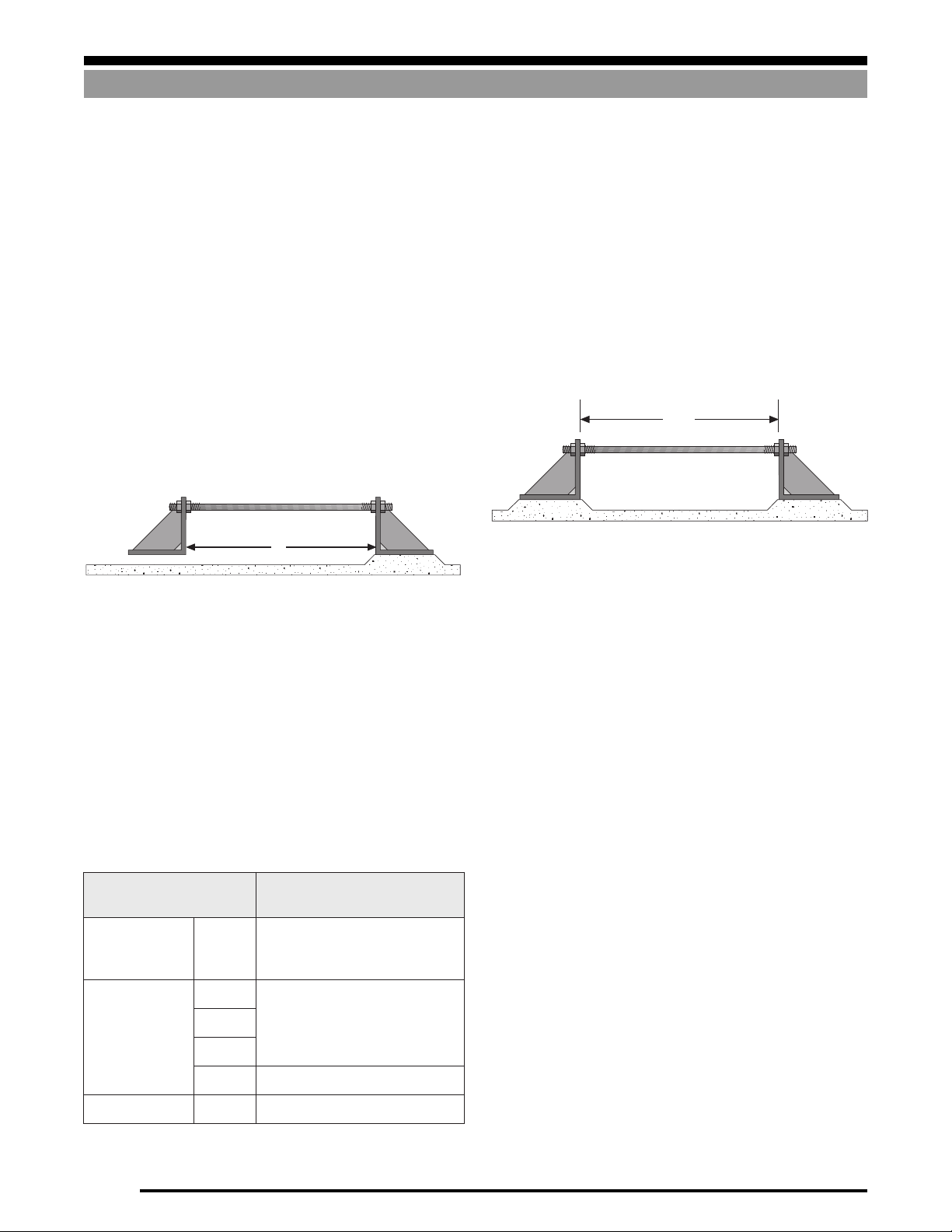
Figure 1-19 illustrates a stay rod rigidly attached to a bracket on
each end—one bracket is rigidly mounted, the other is unattached,
thus allowing the rod to expand and contract freely. As the temperature rises or drops, the length of the rod will increase or
decrease respectively. The change in length (∆L) is proportional to
the original length (L), the change in temperature (∆T), and the
This shows that a 48" steel rod will increase by .019" as a result of
a 60°F temperature rise. This may seem insignificant, until you
consider the forces which can result if the stay rod is confined
rigidly at each end, as in Figure 1-20.
In Figure 1-20, a 1" steel rod 48" long is attached to a bracket on
each end, and both brackets are rigidly attached. If the rod is
initially adjusted so that there is no strain, a subsequent 60°F rise
in temperature will cause the rod to exert a force of 9,000 lb on each
bracket. Hence, vessel restraint systems must be designed and
installed properly so that they don’t move and/or apply large lateral
forces to the weigh vessel.
coefficient of linear expansion (a) which is a characteristic of the
rod material.
∆L can be calculated from the following equation:
∆L = a x L x ∆T
L
Vessel Expansion/Contraction
Figure 1-19
Table 1-1 below lists the coefficient of thermal expansion (α) for
various materials used to construct vessels and stay rods.
Example:
If the rod in Figure 1-19 is made from 1018 steel, then a = 6.5 x 10
6
from Table 1-1. If the rod is 48" long and the temperature
increases by 60°F, the length of the rod will increase by:
∆L = a x L x ∆T
∆L = 6.5 x 10-6 x 48" x 60
∆L = .019
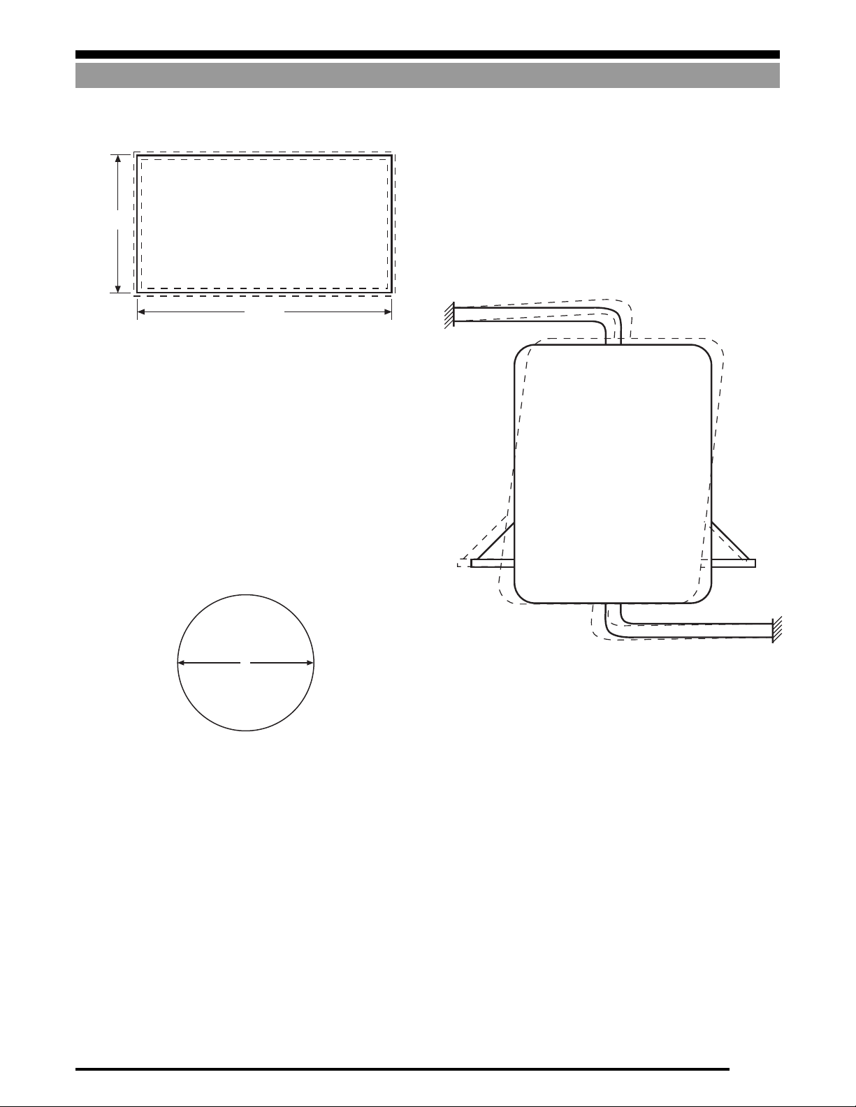
Temperature fluctuations will cause weigh vessels to grow and
contract. Figure 1-21 on the following page best illustrates this.
Shown is a top view of a rectangular vessel. The solid line repre-
sents its size at 70°F and the inner and outer broken lines represent
its size at 40°F and 100°F respectively. The amount that the sides
-
will increase/decrease in length can be found using the expansion
formula discussed previously.
48"
1" Dia
Figure 1-20
Therefore: ∆L = X x L x ∆T
lairetaM
leetSwoL
nobrac
)8101(
leetssselniatS20301x6.9
303
403
61301x9.8
munimulA160601x0.31
Table 1-1
1-12
6-
01x5.6
6-
6-
6-
noisnapxEraeniLfotneiciffeoC
repsehcni( ° )F
Page 15
Thermal Expansion
Vessels with attached piping can be subjected to severe side forces
as a result of temperature variations if the connections are not
executed properly. It is worth noting that vessels expand and
84.0"
144.0"
Figure 1-21
If the vessel is made from mild steel, the length will vary by ± .028"
(6.5 x 10-6 x 144 x 30), and the width will vary by ± .016"
(6.5 x 10-6 x 84 x 30) as the temperature fluctuates by ± 30°F. It will
be apparent that if the load cell is held rigidly by the mount,
enormous side forces will be applied to the cell, hence the need to
use a mount which can accommodate vessel expansion/contraction due to changes in temperature.
In the case of a cylindrical vessel, the change in diameter (∆D)
resulting from a change in temperature (∆T) is given by:
∆D = a x D x ∆T
contract vertically as well as horizontally with changes in tempera-
ture. Rigidly-attached piping may magnify the effects of this
expansion, as seen in Figure 1-23. See Attaching Piping to Weigh
Vessels in Section 3 for detailed guidelines on this subject.
SYSTEM DESIGN
D
Figure 1-22
Example:
If a cylindrical vessel is 96" in diameter and made from 304
stainless steel and is subjected to a temperature rise of 80°F
as the result of being filled with a hot liquid, then the diameter
will increase by:
∆D = 9.6 x 10-6 x 96 x 80
= .074"
Figure 1-23
1-13
Page 16
SYSTEM DESIGN
Calculating Tank V olumes
Calculating Tank Volumes
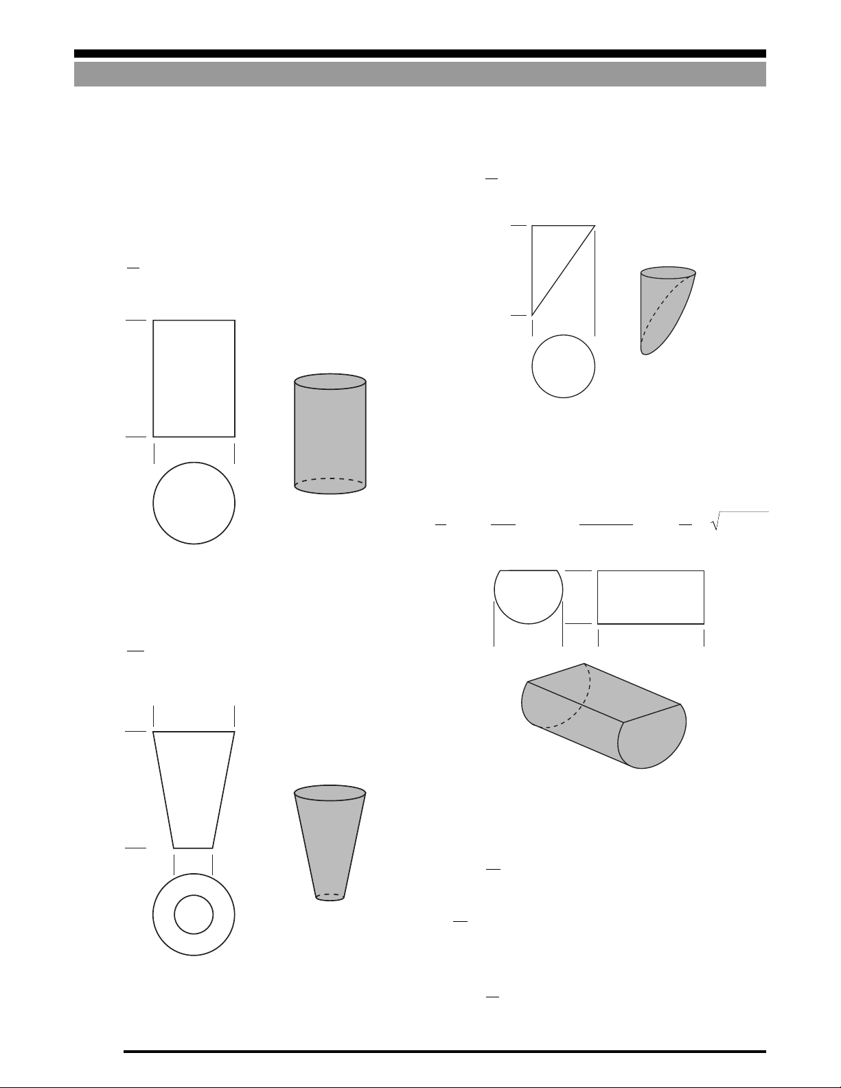
Formulas for V arious Tank Shapes and Sections
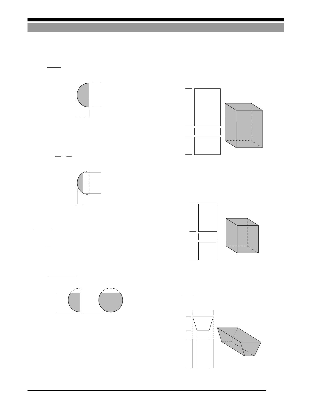
Cylinder
π
Volume =
D2H
4
H
D
Portion of Cylinder
π
2
Volume =
hD
8
h
D
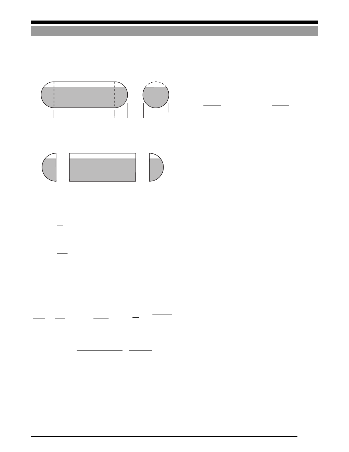
Horizontal Cylinder (Partially Filled)
Volume =
π
D2L −
4
π
720
D2Lcos
2h − D
()
−1
D
+h−
D
2
LhD−h
2
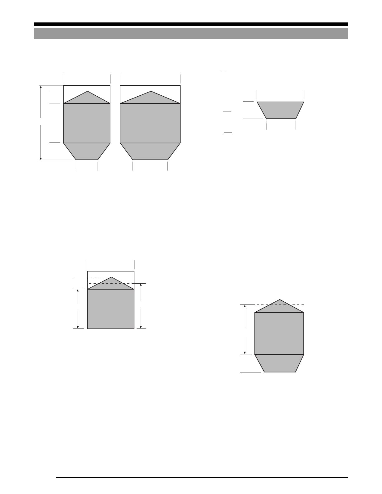
Frustum of Cone
π
hD2+dD+ d
Volume =
()
12
D
h
d
h
L
π
4
D
D2L
2
In the special cases where h=D (that is, the vessel is filled com-
pletely) then this formula reduces to:
Volume =
D
h =
(that is, the vessel is filled half way) then this formula
2
reduces to:
π
Volume =
D2L
8
1-14
Page 17
Calculating Tank Volumes
SYSTEM DESIGN
Hemispherical End
3
π
D
Volume =
12
Spherical Segment
2
Volume =
π
L
2
D
L
+
8
6
Square Prism
(Rectangular Cross Section)
Volume =ABH
D
H
D
2
A
B
Square Prism (Square Cr oss Section)
D
Volume = A2H
L
The radius of the sphere from which the segment is cut is
2
D2+ 4L
r =
8L
D
Note: r
≠
(D is the diameter of the vessel)
2
Hemispherical End (Partially Filled)
π
Volume =
(3h2D− 2h3)
12
h
Wedge I
Volume =
D
a + A
H
A
A
Bh
2
A
h
a
B
1-15
Page 18
SYSTEM DESIGN
13'
4.5'
15'
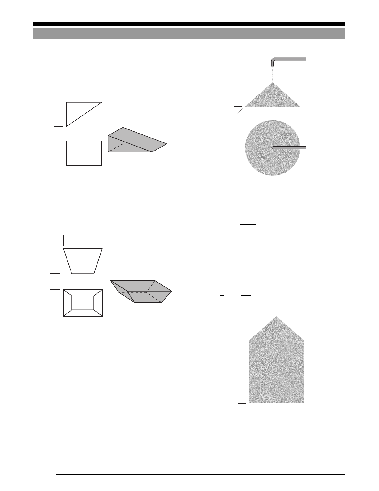
Wedge II
Volume =
hAB
2
Calculating Tank Volumes
h
h
A
B
Frustum of Pyramid
Volume =
h
2 AB + Ab + aB + 2ab
()
6
A
h
a
B
b
α
D
Figure 1-24
The volume of any cone is:
height
x area of base
3
In calculating the volume of material in a vessel, an adequate
approximation can be made by adding 1/3 of the height of the cone
to the height of material up to the cone.
For example, in Figure 1-25, assume the height of the material in
the cylindrical vessel to be 15'+1.5'=16.5 feet.
Thus the volume is calculated using the following formula:
Volume =
π
4
D2h
=
3.14
x (13)2 x 16.5 = 2190 cubic feet
4
Angle of Repose
When a granular material is dropped from above onto a flat surface
it tends to form a cone, as shown in Figure 1-24. The shape of this
cone is described by the angle of repose, α, which is a characteristic
of the material. The angle of repose varies somewhat with particle
size, moisture content, etc. The relationship between α, h, and D
(see Figure 1-24) is:
α
D tan
h =
2
1-16
Figure 1-25
Page 19
Calculating Tank Volumes
SYSTEM DESIGN
Calculation Examples
Example 1
Calculate the volume of liquid in the horizontal tank shown below.
It has hemispherical ends and is filled to a height of 4.5 feet.
4.5'
3' 20' 3' 6'
For ease of calculation, this can be broken into 3 sections
Example 2
If, in the last example, the vessel were filled completely, then the
volume would be:
Total Volume = Volume(a) + Volume(b) + Volume(c)
Example 3
If the vessel in Example 2 is filled with linseed oil, calculate the
weight of material when the vessel is full.
From the section Density of Common Materials, we know that the
density of linseed oil is 58.5 lb/cu. ft. From Example 2, we know
(a) (b) (c)
Step 1
The volume of section (a) or (c) is given by the formula:
Volume =
π
12
where
(3h2D – 2h3)
π
= 3.14,
h = 4.5
,
D = 6
that the volume of the vessel is 678.2 cubic feet.
Weight of Material = Volume x Density
3
π
D
π
D2L
π
D
+
12
3.14(62) x 20
4
= 678.2 x 58.5
= 39,675 lb
12
3.14(63)
12
+
4
+
=
= 56.5 + 565.2 + 56.5
= 678.2 cu ft
3
3.14(63)
+
12
=
3.14
=
=
= 47.7 cu ft
((3 x 4.52 x 6) – (2 x 4.53))
12
3.14
(182.25)
12
Step 2
The volume of (b) is given by the formula:
πD2L
4
3.14 x 62 x 20
π
–
720
where π = 3.14, h = 4.5, D = 6, L = 20
4
=
565.2 – 3.14cos
= 565.2 – 188.4 + 77.94
= 454.7 cu ft
2h – D
D2Lcos
–1
( )
3.14 x 62 x 20cos
–
720
+ h –
D
–1
(.5) + 30√6.75
D
( )
2
–1
2 x 4.5 – 6
( )
6
Step 3
Total Volume=Volume(a)+Volume (b)+Volume(c)
= 47.7 + 454.7 + 47.7
= 550.1 cu ft
L√hD – h
+ 4.5 –
( )
2
6
20√4.5 x 6 – 4.5
2
2
1-17
Page 20
SYSTEM DESIGN
5'
3'
3'
(b)
9.7'
Volume (a)
Volume (b)
3'
Calculating Tank Volumes
Example 4
Calculate the volume of material in the hopper shown below.
Step 2
The volume of section (b) is given by:
Volume =
12'
5'
2'
6'
3'
3'
7'
5'
Step 3
For ease of calculation, this may be broken into 2 sections as
follows:
Step 1
The volume of section (a) is given by:
Volume = ABh
= 5 x 7 x 6.7 = 234.5 cu ft
Example 5
If, in the last example, the vessel was filled to overflowing, then the
volume would be :
5'
Volume(Total) =Volume (a) + Volume (b)
Volume(b) is same as the previous example (73.0 cu ft)
2'
Volume(a) = 5 x 7 x 9.7 = 339.5 cu ft
h
2AB+ Ab + aB +2ab
()
6
3
6
3
6
= x ((2 x 5 x 7) + (5 x 5) + (3 x 7) + (2 x 3 x 5))
= x 146 = 73.0 cu ft
Total Volume=Volume (a) + Volume (b)
= 234.5 + 73.0
= 307.5 cu ft
6'
(a)
6.7'
where the “leveled height” is assumed to be 6.7'.
1-18
Volume(Total) = 339.5 + 73.0 = 412.5 cu ft
Page 21

Material Densities
Densities of Common Materials
SYSTEM DESIGN
Bulk Density Angle of
Material lb/cu. ft. Repose
Abrasive 150
Abrasive Mix 153
Acetylenogen 70-80
Acid Phosphate 60
Adipic Acid 45
Alfalfa, ground 16 45
Alfalfa, seed 48
Almonds, broken or whole 28-30
Alum, pulverized 45-50 30-45
Alumina 60-120 30-45
Aluminate Gell 45
Aluminum Chips 7-15
Aluminum Etchant 54
Aluminum Filament 74
Aluminum Ore (Bauxite) 89-94
Aluminum Powder 47-79
Aluminum Sulfate 58-69
Amianthus 20-40
Ammonium Chloride 52
Ammonium Nitrate 45-62
Andalusite 49
Antimony Oxide 45
Apple Slices, dried 15
Apple Pumice, dried 15
Arsenic 30
Arsenic Oxide 100-120
Asbestos Fiber 19
Asbestos Ore 81
Asbestos Shorts 25
Ashes, dry 35-40 45+
Asphalt, crushed 45 30-45
Bagasse 7-10 45+
Bakelite, powdered 30-40
Barite 100-160
Barium Carbonate 45-97
Bark, wood 10-20 45+
Barley 38 up to 30
Basalt 184
Batch, glass 90-100
Bauxite, crushed 75-85 30-45
Beans, castor 36 up to 30
Beans, navy 48-54 up to 30
Beans, soy 45 up to 30
Beets 45
Beet pulp 25-45
Benzene Hexachloride 56
Bicarbonate of Soda 41
Binder 812 41
Black Coloring 30
Blood, ground 30
Bluestone 60-70
Bulk Density Angle of
Material lb/cu. ft. Repose
Bones, crushed 35-40
Bones, ground 50
Boneblack 20-25
Bonechar 40
Borax 60
Borax, powdered 53
Borton 75
Bran 10-20 30-45
Brass, cast 519
Brass, rolled 534
Brewers grain, wet 55-60 45 & up
Brick, best pressed 150
Brick, tire 137
Brick, soft interior 100
Bromoseltzer 37
Bronze chips 30-50
Bronze powder 75
Cab O Sil 1
Calcin flour 75-85
Calcium Fluoride 82
Calcium Lactate 26-29
Calcium Phosphate 40-50
Carbon activated 8-20
Carbon, black pellet 25 up to 30
Carbon, black powdered 4-6
Carbon lampback 7
Carbon, masterbatch 40
Carborundum 100
Casem 38
Caustic, soda 88
Caustic, soda flakes 47
Celation FP4 14
Celite 535 9
Cement Bulk 75-95
Cement, clinker 75-85 30-40
Cement, portland 90 30-45
Cement, slurry 90-100
Chalk, crushed 85-90
Chalk, ground 70-75
Chalk, lumpy 82-95 45 & up
Chalk, pulverized 70-75
Charcoal 18-25
Cherry wood 42
Chickory 33
Chili spice 45
Chocolate powder 40
Chrome ore 125-150
Cinders, coal 40 25-40
Clay, ceramic, dry 65-80
Clay, fire 40
Clay 96
1-19
Page 22

SYSTEM DESIGN
Material Densities
Bulk Density Angle of
Material lb/cu. ft. Repose
Clay, potters 100-120
Clay, product 36
Clover, seed 48
CMC Powder 52
Coal Anthracite (solid) 94
Coal Bituminous (loose) 43-50 30-45
Coal Char 24
Coal, dust 35
Coal, sized 50
Cobalt Oxide 114
Cocoa, beans 30-45
Cocoa, flavoring 55
Cocoa, powdered 33-35
Coconut 20-22
Coconut, shredded 20-25 45 & up
Coffee 20
Coffee, fresh beans 30-40 30-45
Coffee, green beans 32-45
Coffee, roasted bean 22-30 up to 30
Coffee, soluble 19
Coke, calcined 35-45
Coke, loose 23-32 30-45
Collupulin 19
Compost 28 30-45
Concrete, sand & gravel 150
Cookie Meal 38
Copper, cast 542
Copper, ore 120-150 30-45
Copper, sulfate 60-70 31
Copra 22-33
Copra, cake ground 40-45
Copra, meal 40-45
Cork, granulate (1/2) 12-15
Cork, granules 4
Cork, solid 15
Corn, cracked 40-50
Corn, grits 40-45 30-45
Corn, meal 32-40
Corn, seed 45
Corn, shelled 45 up to 30
Cottonseed, cake 40-45 30-45
Cottonseed, flakes 20-25
Cottonseed, meals 35-40 30-45
Cottonseed, meats 40 30-45
Cryolate (1/2) 90-110 30-45
Cryolite (100) 50-75
Diatomaceous Earth 11-17
Dracalcium Phosphate 40-50
Disodium Phosphate 25-31
Dolomite 83
Dolomite, lumpy 90-100 30-45
Bulk Density Angle of
Material lb/cu. ft. Repose
Dolomite, pulverized 46
Donut Mix 45
Earth 76
Earth, common dry 70-80 30-45
Earth, moist 30-35 30-45
Ebonite 65-70
Egg Yolk 23
Elm, dry 35
Feldspar (1/8) 100-160
Feldspar, (1-100) 65-75
Feldspar, ground 65-70
Feldspar, lumps 85-95 34
Ferro Silicon 87
Ferrous sulfate 50-75
Fine, powder 127
Fit 24-33
Fish, scrap 40-50
Flaxseed 43-45
Flaxseed, meal 25
Flaxseed, whole 45 up to 30
Flour 42-48
Flour, wheat 35-40 45 & up
Flue, dust, dry 110-125
Fluospar 82
Fluospar, lumps 80-110 45 & up
Fluospar, solid 200
Fly ash 61-95
Fly ash, dry 35-40
Foundry sand, loose 80-90
Foundry sand, rammed 100-110
Frodex 24 38
Fullers Earth (burnt) 40 23
Galena 240-260
Garbage 30
Geon Resin 22
Gilsonite 37
Glass, broken 80-100
Glass, frits 128
Glass (window and plate) 161
Glue 52
Glue, ground 40
Glue, pearl 40
Gluten meal 40 30-45
Gold powder 53
Granite, lumps 96 30-45
Granite, solid 150-170 30-45
Granular material 48
Graphite, flake 40
Graphite, ore 65-75
Grape pomace 15-20
Grass, seed 10-12
1-20
Page 23

Material Densities
SYSTEM DESIGN
Bulk Density Angle of
Material lb/cu. ft. Repose
Gravel, dry 90-100 30-45
Green powder 57
Green stone 107
Ground bone 50
Guar Gum 35
Gumbase 42
Guano 70
Gypsum, crushed 90-100
Gypsum, ground 75-80
Hash, spice 66
Hay, loose 5
Hell blue dye 19
Hemlock 25
Hexanedioic Acid 45
Hickory, dry 25
Ice, crushed 35-45 up to 30
Ice, solid 57.4
Insecticide 46
Ional 47
Iron, cast ductile 444
Iron, cast gray 450
Iron Ore 120-180
Iron oxide 174
Iron oxide, black 160
Iron Sulfate 50-75
Kaolin, clay 160
Kaolin, talc 42-56
Lactose 32
Lamisay flour 34
Latikra 34
Lead, arsenal 72
Lead, carbonate 240-260
Lead, ore 180-230
Lead, red 230
Lead, white 250-260
Lignite 42-55 30-45
Limanite 120
Lime, bricks 41-83
Lime, ground 60
Lime, hydrated 40 30-45
Lime, pebble 53-56
Lime, quick 54
Limestone 100
Limestone, agriculture 68
Limestone, dust 55-95
Limestone, filler 63
Limestone, loose 100
Limestone, pulverized 85-90 45 & up
Lindane 56
Linseed, cake 48-50
Linseed, whole 45-50 up to 30
Bulk Density Angle of
Material lb/cu. ft. Repose
Magnesia 77
Magnesium chloride 33
Magnesium oxide 10-135
Magnesium, sulfate 40-50
Mahogany Spinach 53
Maize 45
Malt, flour 40
Malt, meal 36-40
Malt, powder 40
Malt, wheat 41
Manganese Ore 125-180
Manganese Oxide 120
Manganese Sulfate 70
Manganese Solid 475
Manure 25
Marble, crushed 80-95 30-45
Maple 49
Masonry 185
Material 199 67
Meat 50-55
Mercury 849
Metallic, flake 35
Mica, ground 13-15 30-45
Mica, flakes 17-22
Mica, solid 181
Mica, soapstone 46
Milk, malted 27-35 45 & up
Milk, powdered 36 45 & up
Mill Scale 100-125
Milltown 35
Mineral Oxide 35
Molybdenum 107
Mortar, wet 150
Moulding compound 42
Muriate of Potash 77
Mustard, powdered 16
Mustard, spice B 45
Naphthalene Flakes 36
Neutral Granules 24
Nickel Ore 150
Nicotinic Acid 35
Oskite 60
Oak, live, dry 59
Oats 25-35 32
Oat flour 33
Oil cake 48-50
Oil, linseed 58.8
Oleomargarine 59
Orange Peel, dry 15
Paper Pulp (15%) 62
Paper Pulp (6 15%) 60-62
1-21
Page 24

SYSTEM DESIGN
Material Densities
Bulk Density Angle of
Material lb/cu. ft. Repose
Parazate 18
Peanut Brittle 36
Peanuts, unshelled 15-24 30-45
Peas 45-50
Pentserythritol 43
Peppermint 32
Pharmaceutical Mix 39
Pharmaceutical Lubricant 9
Phenol Formaldehyde 30
Phosphate 94
Phosphate, crushed 75-85 26
Phosphate, granular 90-100
Phosphate, soda 25-31
Phosphoprotein 36
Pie Crust Mix 34
Pine, white, dry 26
Pine, yellow south 45
Pitch 72
Plastic beads 46
Plastics, chopped 37
Plastics, lrg. flakes 19
Plastics, small flakes 34
Plastics material color 34
Plastics, spheres 42
Plastics, Powder B 25
Plastics, Scrap 40
Polyester, film 5
Polyethylene 42
Polyethylene, flakes 6
Polyethylene, pellets 35
Polyvinyl Chloride 40
Pork Spice 72
Potassium Bromide 114
Potassium Chloride 73 30-45
Potassium Iodate 128
Potassium Nitrate (1/2) 76
Potassium Sulfate 42-48
Potatoes, dried 58
Pie Mix 34
Protein Supplement 33
PVC Powder 30
Quartz 85
Raisins 48
Red Oxide 72
Red Color Concentrates 32
Redwood 26-30
Resin 30-37
Resin Luron 39
Rice, chopped 64
Rice, grits 42-45 up to 30
Rice, rough 32-36 30-45
Rip Rap 80-105
Bulk Density Angle of
Material lb/cu. ft. Repose
Rolaids 64
Rosin 67
Rubber Composition 33
Rubber Caoutchouc 59
Rubber, mfg. 95
Safflower 45
Safflower, cake 50
Sal Ammoniac 52
Salicylic Acid 29
Salt (1/8) 50
Salt, coarse 45-55 30-45
Salt, dry coarse 45-50
Salt, fine 70-80
Sand, damp 110-130 45 & up
Sand, dry 90-110
Sand, foundry (1/8) 90
Sand, foundry (1/2) 90
Sand, rammed 100-110
Sandvoids full of H2O 110-130 15-30
Santonox 18-45
Saran Powder 35
Sawdust (wet) 24
Scale 125-160 36
Sewage 40-50
Shale, crushed 85-90 39
Shale, solid 162
Shavings, wood 15
Silene 15
Silene & Zinc 15
Silica Gel 42
Silicon Carbide 15-88
Silver Powder 69
Sinter 90-110
Slag Furnace (+1/2) 60-65
Slate, crushed 80-90 28
Slate, solid 165-175
Sludge 45-55
Snow, packed 15-35
Soap, flakes 5-20 30-45
Soap, powdered 20-25 30-45
Soapstone 40-50
Soda Ash, heavy 55-65 30-45
Sodium Aluminate 72
Sodium Bisulfate 90
Sodium Chloride 84
Sodium Nitrate 70-80 24
Sodium Phospho Aluminate 67
Sodium Pysophosphate 63
Sodium Sulfate, dry (1/8) 65-85
Sodium Tripolyphosphate 58-64
Sorghum, seed 32-52
Soybeans, cake 40-43
1-22
Page 25
Material Densities
SYSTEM DESIGN
Bulk Density Angle of
Material lb/cu. ft. Repose
Soybeans, flakes, raw 20-26
Soybeans, meal, cold 40
Soybeans, meal, hot 40
Spice (Vienna) 63
Spruce 28
Stabilizer 71
Sta-nut 52
Steatite 25-50
Steel, solid 469.6
Steel Turnings 60-120 45 & up
Sugar Beet, dry 12-15
Sugar Beet, wet 25-45
Sugar, powdered 50-60
Sugarcane 15-18 45 & up
Sulphur, crushed 50-60
Sulphur, dust 50-70 30-45
Sulphur, powdered 50-60
Taconite 116-130
Talc, granulated 50-65
Talcum powder 55
Tanbark 55
Tar 69-75
Tea 27
Tin Cast 459
Timothy, seed 36
Titanium Sponge 60-70
Bulk Density Angle of
Material lb/cu. ft. Repose
Tobacco, scraps 15-25 45 & up
Tobacco, stems 16-25 45 & up
Traprock, compact 187
Tricalcium Phosphate 40-50
Trichlorocyanuric Acid 50
Triple Super Phosphate 50-55
Trisodium Phosphate 60 40
Tumeric 51
Ulexite 75
Vermiculite 62
Vermiculite, ore 80
Vicrum 35
Vinyl Resin 36
Vitamin Mix 43-49
Walnuts 35-40
Wax 26
Wheat, cracked 46 30-46
Wheat, cut 45-48
Wheat germ 35-40
White Powder 28-45
Wood, bark 10-20
Wood, chips 10-30 45 & up
Yellow Corn Flour 33
Zinc Concentrate 75-80
Zinc Hydrosulphate 44
Zinc Oxide, heavy 10-15 45 & up
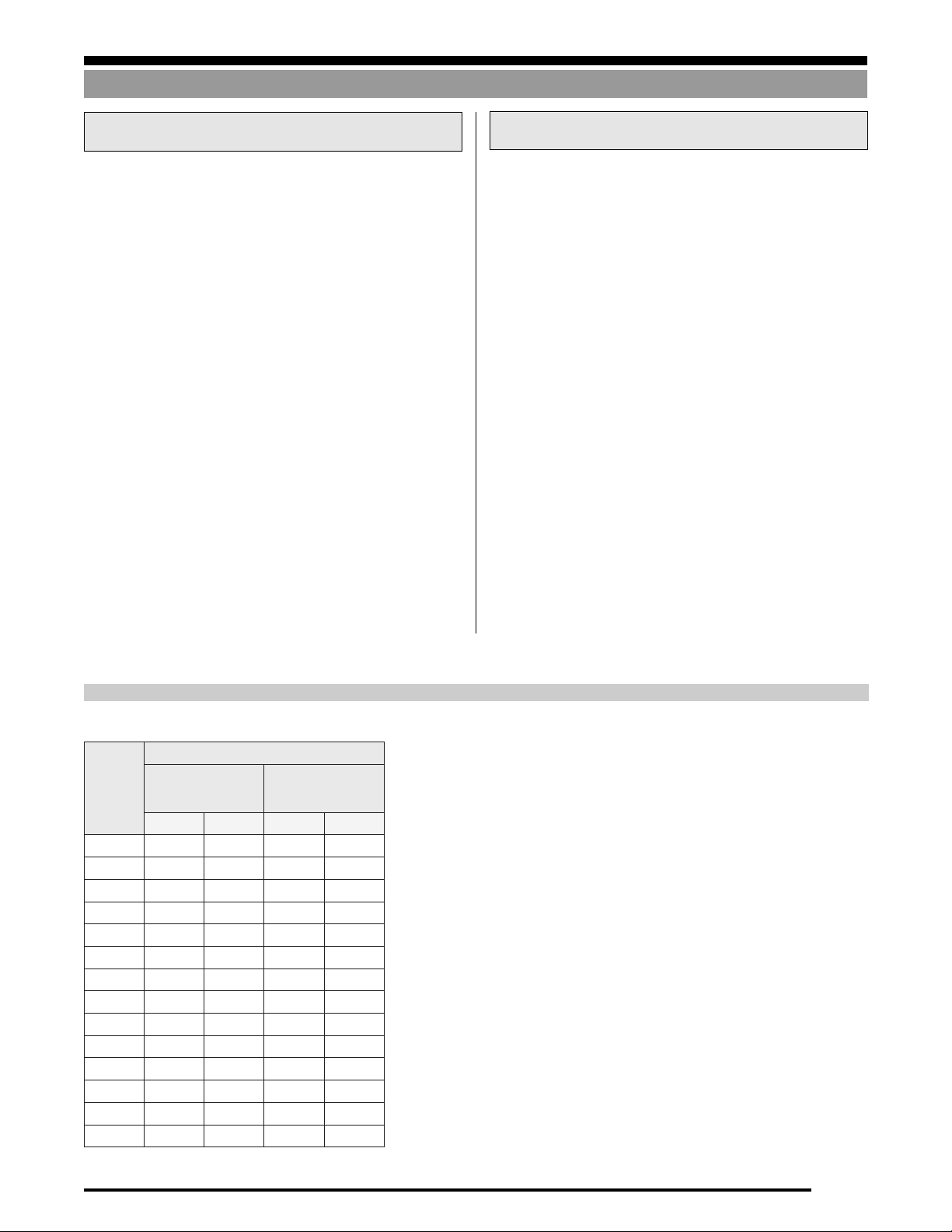
Load Cell Bolt Torque Values
)bltf(euqroTdednemmoceR
8301detaert-taeH
paC
wercs
retemaid
"4/111312151
"61/512325203
"8/383040506
"61/755065859
"2/15859521041
"61/9521041571591
"8/5571012542072
"4/3003033524064
"8/7054094066007
"10865170990501
"8/1-158809907415561
"4/1-15521083100120132
"8/3-15361578105720113
"2/1-10812034204630014
daehxeh
5edargEAS
CNU FNU CNU FNU
daehxehyollA
8edargEAS
Notes:
1) Based on dry assembly. Variables such as lubrication, plating, etc. may
reduce the values listed above as much as 20%, and must be taken into
consideration.
2) General formula for calculating Torque is as follows: Torque in Inch
lb=0.2 x Nominal Diameter of Screw x Load in lb, where load = 80% of yield
strength, expressed in lb, not pounds per square inch.
3) The tension induced in a cap screw may be checked by measuring overall
length before torquing and then under torque load. The screw stretches
.001" per inch of screw length for each 30,000# PSI induced tension.
Applies only to loads below the yield point.
1-23
Page 26

SYSTEM DESIGN
Wind and Seismic Effects
Wind and Seismic Effects on Vessel Stability
Other than forces resulting from the impact of a vehicle, wind and
seismic forces are the most important external forces which might
affect a weigh vessel. The threat from vehicular traffic can be
guarded against using properly-designed guard rails. The effects of
wind and seismic forces, where they are a factor, must be accounted for in the design of a weigh vessel. At a minimum,
consideration of these forces might affect the capacity of load cells
selected. In more extreme cases they may dictate the use of
additional restraints on a vessel. In general, weigh modules have a
lift-off capacity of 150% of capacity, and a side-load capacity of
100% of capacity.
1/4W + F0T. On the right-hand side load cell mounts, a force of F
is also induced as a result of F, however, this force is in the opposite
direction to the existing 1/4W and the total force here is reduced
to 1/4W - F0T. Hence, you will see that load is being transferred from
the mounts on one side of the vessel to those on the other. The load
cell capacity selected must be capable of withstanding this additional force for the extremes of wind or seismic forces expected. If
F was increased to where F
load on the right hand mounts and the load would have doubled to
W/2 on the left-hand mounts. Further increase in F will cause the
vessel to lift up on the right-hand mounts and may, in the extreme
case, cause the vessel to tip.
0T
equalled W/4 then there would be zero
0T
Figure 1-26
In general, these forces act horizontally at the center of gravity
(CG) of the weigh vessel. Figure 1-26 illustrates a four-legged
vertical cylindrical vessel and the forces acting on it in the absence
of wind or seismic forces. W is the vessel’s weight (an empty and full
vessel should be considered separately, as either one may be the
limiting case), and it acts through the vessel’s center of gravity.
Assuming that the four legs are arranged symmetrically, then each
leg will exert a force of 1/4W on each mount.
Figure 1-27 illustrates the same vessel with the addition of a
horizontal force F (the result of wind or seismic activity.) The
vessel exerts a horizontal force of 1/4 F on each load cell mount.
Also, there is an additional force of F0T acting on the left-hand side
load cell mounts, which means that each is now carrying a load of
1-24
The relationship between F0T and F may be stated as follows for the
vessel shown in Figure 1-27:
where h = height to the center of gravity and D = vessel diameter.
It is desirable to reduce F0T; this can be done as might be expected
by reducing F or h or by increasing D. Dimension h can be reduced
by reducing the vessel height (not always practical) or by placing
the mounts at the vessel’s center of gravity as illustrated earlier. In
this case h = 0 and hence F0T = 0.
Figure 1-27
F0T = .7Fh/D
Page 27

Wind and Seismic Effects
SYSTEM DESIGN
It is interesting to compare the stability of a vessel supported on 3
and 4 load cell mounts. Figure 1-28 shows a top view of a vertical
cylindrical vessel supported at 3 and 4 points (broken and solid
lines respectively). The vessel will tend to tip about a straight line
drawn between adjacent support points; the greater the distance
from the center of gravity to this line the more stable the vessel will
be. A vessel supported at 3 points will be approximately 29% less
stable than if it were supported at 4 points.
Wind Forces
Consideration must be given to the effects of wind loading when a
weigh vessel is installed outdoors. This is particularly important
for tall slender vessels, vessels installed in exposed locations (for
example, facing a large body of water), or those installed in a high
wind-speed location. In analyzing the effects of wind loading, it
must be assumed that the wind may blow at a vessel in any
horizontal direction.
Figure 1-29 illustrates the effect of wind blowing at a vertical
cylindrical vessel. Note that not only is there a force exerted against
the windward side of the vessel, but there is also a suction force on
the leeward side. These forces are additive, and tend to tip the vessel
in the direction of the wind. At right angles to the wind direction
are suction forces pulling on each side due to the increased speed
of the wind at these points. Since these are equal and opposite in
.25D
CG
.5D
.35D
direction, they have no net effect on the stability of the vessel.
D = Diameter
CG = Center of Gravity
= 3 point support
= 4 point support
Figure 1-28: Top view of cylindrical vessel
Because of the many variables in vessel design and site conditions,
it is impossible to deal comprehensively with the calculation of
wind and seismic forces in this text. However, the following
subsections deal with these forces in general terms and point out
the information necessary for a complete analysis. Refer to the
Uniform Building Code (UBC) for further details.
While the effects of both wind and seismic forces should be
considered, it is acceptable to consider these forces in isolation.
To perform a complete wind force analysis, the following
information is necessary:
■ Vessel: The vessel’s dead and live weights, number of supports,
and overall dimensions such as height, length of legs, diameter,
etc.
■ Minimum basic wind speed: This may be taken from Figure
1-30, which is a map of the USA superimposed with wind speed
contours. This map is based on a 50-year mean recurrence interval
which has traditionally been accepted as a reasonable risk. If local
records indicate higher 50-year wind speeds, then the higher
values should be used. This map does not consider the effects of
tornadoes.
WIND DIRECTION
Figure 1-29
1-25
Page 28

SYSTEM DESIGN
Wind and Seismic Effects
■ Exposure: The exposure conditions at the site must be known.
Built up or rough terrain can cause a substantial reduction in wind
speed. The United Building Code (UBC) defines 3 exposure categories:
Exposure B: has terrain with buildings, forest or surface irregularities 20 feet or more in height covering at least 20% of the area
extending one mile or more from the site.
Exposure C: has terrain which is flat and generally open, extending one half mile or more from the site in any full quadrant.
Exposure D: represents the most severe exposure in areas with
■ Importance Factor: An importance factor of 1.15 is used for
essential facilities which must be safe and usable for emergency
purposes after a windstorm in order to preserve the health and
safety of the general public. Such facilities include medical facilities having surgery or emergency treatment areas, fire and police
stations. A factor of 1.0 is used for all other facilities.
With this information, the wind forces can be calculated in accordance with methods described in the UBC. This information may
be used to verify the stability of the vessel using standard mounts,
or to design additional restraints if deemed necessary.
basic wind speeds of 80 mph or greater and has terrain which is flat
and unobstructed facing large bodies of water over one mile or
more in width relative to any quadrant of the vessel site. Exposure
D extends inland from the shoreline 1/4 mile or 10 times the vessel
height, whichever is greater.
90
80
100
70
70
80
100
90
80
90
90
70
80
70
90
70
70
90
80
70
80
70
NOTES: Basic wind speed 70 mph Special wind region
1. Values are fastest mile speeds at 33 feet above ground for Exposure Category C and are
associated with an annual probability of 0.02.
2. Linear interpolation between wind speed contours is acceptable.
3. Caution in use of wind speed contours in mountainous regions of Alaska is advised.
4. Wind speed for Hawaii is 80 and Puerto Rico is 95.
5. Wind speed for Alaska varies from 70 inland to over 110 in coastal areas.
6. Where local records or terrain indicate higher 50-year wind speeds, they shall be used.
7. Wind speed may be assumed to be constant between the coastline and the nearest inland contour.
70
80
70
80
90
90
100
80
110
110
110
100
110
Figure 1-30
1-26
Page 29

Wind and Seismic Effects
SYSTEM DESIGN
Seismic Forces
■ Function of Structure. Does the vessel :
Figure 1-31 is a seismic zone map of the United States. The various
zones are numbered 0 (little likelihood of damage) through 4
(likelihood of major damage) which indicate, on an ascending
scale, the severity of damage likely as the result of earthquakes. The
effects of seismic forces should be considered on vessels being
installed in zones 1 through 4.
The following information is required in order to perform a
complete seismic analysis.
■ Vessel: The vessel’s dead and live weights, number of supports, and overall dimensions such as height, length of legs,
diameter, etc.
■ Site geology/soil characteristics and the vessel’s structural
■ The seismic zone (from Figure 1-31) in which the vessel will
be installed.
■ Is the vessel freestanding, mounted on a structure, or on the
roof of a building?
3
2B
2B
3
4
3
2B
3
4
2B
3
1
4
1
0
0
With this information, the forces resulting from seismic activity
can be calculated according to methods described in the Uniform
Building Code (UBC).
1
2A
1. Contain material or equipment necessary for the protection of essential facilities (hospitals, fire and police stations), hazardous facilities or special occupancy structures (schools, jails and public utilities)?
2. Contain sufficient quantities of toxic or explosive substances to be dangerous to the safety of the general public
if released?
3. Support the operation of public utility facilities?
4. Perform a function not listed above.
period, if available.
2A
1
0
1
1
2A
2A
ALASKA
HAWAII
1
2B
1
2A
2B
3
1
0
2B
3
4
3
0
1
2B
1
2B
3
4
1
3
1
0
1
2A
0
Figure 1-31
1-27
Page 30

WEIGH MODULES
WEIGH MODULES
Single-End Beam Load Cell Modules.............................................................................. 2-2
Introduction ...................................................................................................................................................................... 2-2
General Mounting Principles ............................................................................................................................................. 2-2
Single-End Beam Orientation............................................................................................................................................ 2-2
Rice Lake Weighing Systems Weigh Modules.................................................................................................................... 2-3
Survivor® 1700HE Modules ...........................................................................................................................................................2-3
RL50210 TA Modules......................................................................................................................................................................2-4
RL1800 Modules .............................................................................................................................................................................2-5
Survivor® 1855HE Modules ...........................................................................................................................................................2-6
RL1900 Modules .............................................................................................................................................................................2-7
Paramounts® HS & Paramounts® EP............................................................................................................................................2 -8
Double-End Beam Load Cell Modules........................................................................... 2-10
Introduction .....................................................................................................................................................................2-10
General Mounting Principles............................................................................................................................................2-10
Double-End Beam Orientation .........................................................................................................................................2-10
Rice Lake Weighing Systems Weigh Modules...................................................................................................................2-11
RL1600 Modules ...........................................................................................................................................................................2-11
Survivor® 2100HE Modules .........................................................................................................................................................2-12
EZ Mount 1 ...................................................................................................................................................................................2-13
TSA Truck Scale Modules.............................................................................................................................................................2-14
TranslinkTM Truck Scale Modules ................................................................................................................................................... 2-1
Compression Canister Load Cell Modules ..................................................................... 2-16
Introduction .....................................................................................................................................................................2-16
General Mounting Principles............................................................................................................................................2-16
Rice Lake Weighing Systems Weigh Modules...................................................................................................................2-16
RLC Weigh Modules .....................................................................................................................................................................2-16
MagnaMount® Tank, Truck & Railroad Track Mounts ...............................................................................................................2-17
65092 Tank Mounts......................................................................................................................................................................2-18
S-Beam Load Cell Modules.......................................................................................... 2-19
Introduction .....................................................................................................................................................................2-19
General Mounting Principles............................................................................................................................................2-19
Rice Lake Weighing Systems Weigh Modules...................................................................................................................2-20
ITCM Mounts ................................................................................................................................................................................2-20
Mounting Assemblies and Compatible Load Cells.......................................................... 2-22
2-1
Page 31

WEIGH MODULES
Single-Ended Beams
Single-End Beam Load Cell Modules
Introduction
Single-end beam load cells offer many advantages when used in well-designed weigh modules. The modules using single-end beam load
cells have a low profile, and are generally self-checking. Load cell replacement is possible in most single-ended beam mount systems by
raising the vessel only enough to remove pressure from the cell.
General Mounting Principles
• The mounting surface should be flat and level.
• The mounting block should be thick enough to provide
adequate threads for the mounting screws.
• The corner of the mounting surface (where the cell cantilevers out) must be hard to prevent peening.
• The mounting bolts should be at least grade five to prevent
stretching or the possibility of breaking.
• The load should be applied vertically through the center line
of the load hole (the load may be applied from above, as
illustrated in Figure 2-1, or may be hung from below).
• The load introduction means must provide flexibility to avoid
the transmission of extraneous forces and to tolerate the
unavoidable deflection of the load cell itself.
• The mounting bolts should be torqued to specified values.
Figure 2-1
Single-End Beam Orientation
Figure 2-2 illustrates four different vessels and recommended
mounting configurations for single-end beam weigh modules. See
the subsection on Paramounts® for special movement considerations that apply to this unique single-ended beam system.
The vessels in the upper row, at right, illustrate a vertical cylindrical vessel. Note that the longitudinal axis through each load cell
points towards the center of the vessel.
This principle could also be used for the vessels in the lower row,
if it were convenient to mount the cells in each corner with the
longitudinal axis pointing toward the center. However, it may be
more convenient, and is acceptable, to mount the cells as illustrated. As these cells are relatively immune to extraneous forces
applied along the longitudinal axis of the cell, it should point in the
direction of any prevalent side force (for example, on a roller
conveyor, the load cells should point in the direction of travel).
Figure 2-2
2-2
Page 32

Single-Ended Beams
Rice Lake Weighing Systems Weigh Modules
WEIGH MODULES
SURVIVOR® 1700HE Modules
These light- to medium-capacity modules use single-ended beam
load cells in capacities from 5 kg-250 kg (11-550 lb) and 500-5,000
kg (1,100-11,000 lb). The SURVIVOR 1700HE is ideally suited for
light- to medium-capacity micro-ingredient batching and mixing
in a variety of hostile environments, especially where moisture is
present. This module provides superior corrosion, moisture ingress, and mechanical protection. The load cells are waterproof
guaranteed and OIML C3 certified (20 kg-5,000 kg) to offer the
ultimate in durability and accuracy.
Typical Application
Typical applications for the Survivor 1700HE include light-capacity micro-ingredient batching and mixing.
Allowable Movement
Figure 2-3 illustrates the 1700HE module’s capability to handle
movement. The load may be checked in one of two directions. This
allows positioning in one of two orientations for proper checking.
Figure 2-3: SURVIVOR 1700HE
Construction and Features
1) IP66/68 environmental rating is guaranteed against moisture
damage.
2) Load introduction mechanism isolates load from overloads,
underloads and extreme side loads, minimizing mechanical
failure.
3) Weldless construction improves pressure washdown performance.
4) Integral jacking/shipping bolts offer a means to remove the
load from the load cell for quick removal and replacement of
load cell and worry-free transport.
5) All modules come standard in stainless steel.
Figure 2-4: SURVIVOR 1700HE in micro-ingredient batching
2-3
Page 33

WEIGH MODULES
a
a
aa
a
aaa
a
a
a
a
a
a
aa
a
a
aa
a
a
a
a
a
aa
aa
a
a
a
a
a
a
a
a
a
a
aa
a
aa
aaa
a
a
a
a
a
a
a
aa
a
a
aa
a
a
a
a
a
aa
aa
a
Single-Ended Beams
RL50210 TA Modules
These low-capacity modules use single-ended beam load cells in
capacities from 50 lb to 2,500 lb. The resiliency of a neoprenecushioned mounting pad attached directly to the cell and vessel
accommodate limited movement and minor misalignment. These
units are ideal for small tanks, platforms, and in-motion conveyor
applications where checking requirements are low. The direct
connection of the vessel to the flexible neoprene pad acts to
cushion shock loads.
Allowable Movement
Figure 2-5 illustrates the RL50210 TA module’s capability to
handle movement. The arrows indicate the various means by
which the load introduction plate can move relative to the cell to
minimize the transfer of extraneous forces.
6) Capacities 500 lb to 2,500 lb incorporate an overload stop
7) Capacities 50 lb to 250 lb accommodate an RL50210 load cell
Typical Application
These modules should be attached so their longitudinal axis aligns
with the direction of greatest expected movement of the vessel or
conveyor. On a roller conveyor, this would normally be along the
line of conveyor travel.
under the free end of the cell.
while capacities 500 lb to 2,500 lb accommodate an RL30000
load cell.
Figure 2-5: RL50210 TA
Construction and Features
1) The module has a large base plate and spacer washer, and the
load cell is screwed directly to the base plate.
2) Load introduction is through a steel plate bonded to a
neoprene pad which accommodates vessel movement in all
directions.
3) Because the module can compress vertically, it provides a
degree of protection against shock loading.
4) Because of the neoprene pad, this module provides little liftoff protection or lateral restraint. Also, because the neoprene
pad compresses as load is applied, this module should not be
used where the vessel has attached piping or stay rods. Loosely
fitting safety check rods may be used if required.
5) This module is available in capacities from 50 lb to 2,500 lb in
mild steel, and 500 lb to 2,500 lb in 304 stainless steel.
Figure 2-6: RL50210 TA on conveyor
2-4
Page 34

Single-Ended Beams
a
a
a
a
a
a
a
aa
a
aa
aaa
a
a
a
a
a
a
a
aa
a
a
aa
a
a
a
a
aaa
a
a
aa
a
aaa
a
a
a
a
aa
a
a
a
a
a
aa
a
a
a
a
aa
a
a
a
a
a
a
a
a
a
a
WEIGH MODULES
RL1800 Modules
These modules use single-end beam load cells in center-pivoted
modules with capacities up to 10,000 lb per module. While these
are compression-style modules, the cell is actually mounted in
tension since the load is introduced through a center loading bolt
in a hanging trunnion suspended beneath the load cell. The
trunnion can pivot in all directions on a set of spherical washers,
allowing the top plate (attached to the vessel) to rock without
twisting the load cell. This arrangement makes the modules selfcentering, and able to accommodate movement in all directions.
This module is self-checking and provides lift-off protection.
The RL1800 modules allow the installer to adjust overall height
easily with the center loading bolt that is attached to the hanging
trunnion. This adjustment feature speeds the process of equalizing
the load between all modules. These modules allow load cell
removal and replacement without raising the tank—an important
consideration in some installations.
Allowable Movement
Figure 2-7 illustrates the RL1800 module with arrows indicating
allowable movement.
Construction and Features
1) A base plate and spacer support the load cell.
2) A trunnion block is suspended below the free end of the cell
3) A chair arrangement is attached to the trunnion block through
4) Because the load is suspended from the underside of the cell,
5) The module provides lift-off protection and lateral restraint.
6) The module provides height adjustment.
7) This module can accommodate a broad range of alloy steel,
8) The RL1800 module is available in capacities from 250 lb to
and is attached to the cell using a bolt in tension which is
screwed into a threaded load hole. A spherical washer set is
placed between the bolt head and block.
pivot screws, and the load is applied to the top plate of this
chair. This arrangement allows the chair to move in the
directions indicated in Figure 2-7.
the module is self-centering; that is, after a disturbance
temporarily moves the top plate laterally, it will tend to return
to its original position under the influence of gravity.
stainless steel and hermetically-sealed stainless steel load
cells.
10,000 lb in both mild steel and 304 stainless steel.
Figure 2-7: RL1800
Typical Installation
Figure 2-8: RL1800 modules on
horizontal cylindrical tank
Loading
Bolt
2-5
Page 35

WEIGH MODULES
a
a
a
a
a
a
a
aa
a
aa
aaa
a
a
a
a
a
a
a
aa
a
a
aa
a
a
a
a
aaa
a
a
aa
a
aaa
a
a
a
a
aa
a
a
a
a
a
aa
a
a
a
a
aa
a
a
a
a
a
a
a
a
a
a
Single-Ended Beams
SURVIVOR® 1855HE Modules
These modules use single-ended beam load cells in center-pivoted
modules with capacities up to 10,000 lb per module. Load cells are
NTEP-certified, 1:5000 divisions Class III load cells for up to 0.02%
total error. While these are compression-style modules, the cell is
actually mounted in tension since the load is introduced through
a center loading bolt in a hanging trunnion suspended beneath the
load cell. The trunnion can pivot in all directions on a set of
spherical washers, allowing the top plate (attached to the vessel) to
rock without twisting the load cell. This arrangement makes the
modules self-centering, and able to accommodate movement in all
directions. This module is self-checking and provides lift-off protection.
The 1855HE modules allow the installer to adjust overall height
easily with the center loading bolt that is attached to the hanging
trunnion. This adjustment feature speeds the process of equalizing
the load between all modules. These modules allow load cell
removal and replacement without raising the tank—an important
consideration in some installations.
Allowable Movement
Figure 2-9 illustrates the 1855HE module with arrows indicating
allowable movement.
Construction and Features
1) A base plate and spacer support the load cell.
2) A trunnion block is suspended below the free end of the cell
3) A chair arrangement is attached to the trunnion block through
4) Because the load is suspended from the underside of the cell,
5) The module provides lift-off protection and lateral restraint.
6) The module provides height adjustment.
7) Hermetically-sealed stainless steel load cells are guaranteed
8) The 1855HE module is available in capacities from 1000 lb-
9) A Teflon®-jacketed cable and integral conduit adapter heighten
and is attached to the cell using a bolt in tension which is
screwed into a threaded load hole. A spherical washer set is
placed between the bolt head and block.
pivot screws, and the load is applied to the top plate of this
chair. This arrangement allows the chair to move in the
directions indicated in Figure 2-9.
the module is self-centering; that is, after a disturbance
temporarily moves the top plate laterally, it will tend to return
to its original position under the influence of gravity.
against moisture damage.
10,000 lb in stainless steel
chemical and moisture resistance.
Figure 2-9: SURVIVOR 1855HE
Typical Installation
Figure 2-10: SURVIVOR RL1800 Modules on
Horizontal Cylindrical Tank
Loading
Bolt
Teflon is a registered trademark of E.I. Dupont
2-6
Page 36

Single-Ended Beams
WEIGH MODULES
RL1900 Modules
The RL1900 module is similar in design to the RL1800, but
accommodates slightly more lateral movement than the RL1800.
Allowable Movement
6) The module provides lift-off protection and lateral restraint.
7) The module provides height adjustment.
8) The RL1900 module is available in capacities from 1,000 lb to
9) This module can accommodate both environmentally-pro-
Typical Installation
10,000 lb in 304 stainless steel.
tected and hermetically-sealed load cells—the HBM SB3 and
the RTI SSB, respectively.
Figure 2-11: RL1900 Module
Construction and Features
1) A base plate and spacer support the load cell.
2) A trunnion block is suspended below the free end of the load
cell. It is attached to the load cell using a bolt which passes
through the clearance load hole and is retained by a nut at the
top of the cell. Two spherical washer sets are used; one sits
between the bolt head and trunnion block, the other sits
between the nut and the top of the load cell (which is
counterbored to accept the washer set).
3) A chair arrangement is attached to the trunnion block through
pivot screws; the load is applied to the top plate of this chair.
This arrangement allows the chair to move in the directions
indicated in Figure 2-11.
4) This module allows greater lateral movement than the RL1800
by virtue of the fact that the suspension bolt passes through
a clearance load hole in the cell and has spherical washer sets
at the top and bottom.
5) Because the load is suspended from the underside of the cell,
the module is self-centering; that is, after a disturbance
temporarily moves the top plate laterally, it will tend to return
to its original position under the influence of gravity.
Figure 2-12: RL1900 modules on hopper scale
2-7
Page 37

WEIGH MODULES
Single-Ended Beams
Paramounts® HS & Paramounts® EP
The versatile Paramounts vessel weighing system consists of three
Construction and Features
1) No Torsional Effects: All SB4 load cells incorporate a blind
different modules, which together make a complete system of fixed
and sliding modules with single-ended SB4 or SB5 load cells. This
unique system allows a vessel to expand freely on sliding modules,
yet the system is self-checking. All models are available in capacities to 22,500 lb.
Paramounts
TM
Patent #3960229
RICE LAKE WEIGHING SYSTEMS
Rice Lake, WI 54868 U.S.A.
Figure 2-13
Allowable Movement
hole for load introduction. The load is introduced via a convex
loading pin as seen in Figure 2-15. The convex surface allows
the module’s top plate to rock without twisting the cell. The
load pin is centered in the load hole by a pliable polymer “O”
ring. The bottom of the blind hole is located on the neutral
axis of the SB4’s sensing section. Therefore, torsional effects
are virtually eliminated.
Figure 2-15
2) Jacking Screw and Lift-Off Protection: Each module consists
A: FIXED PIN B: FREE SLIDING C: SIDE STOP
Figure 2-14
3) Allows Movement: There are three different styles of mod-
a) Fixed Pin Module - With the fixed pin module, the load is
transferred from the top plate to the load cell via a load pin
which enters a counterbore in the top plate and load cell. The
4) Matched Outputs: The SB4 and SB5 load cells are matched
pin acts as a pivot point and only allows the top plate to rotate
while fixing that corner of the vessel.
b) Free Sliding Module - With the free sliding module, the load
pin has a flat top surface on which the top plate is free to slide
in all directions. To minimize friction, the top surface of the
5) Withstands Hostile Environments: Paramounts HS are avail-
pin is Teflon®-coated and slides on a smooth stainless steel
slider plate. The cleanliness of these two surfaces is assured by
a neoprene suction seal.
c) Side Stop Module - The side stop module uses the same
6) Available in capacities to 22,250 lb in either mild steel or
Teflon®-coated pin and stainless steel slider plate, but in
addition it has side bumpers. These bumpers check the top
plate movement laterally. The top plate is checked to move
only in the direction of the longitudinal axis of the load cell.
A three-cell system uses one of each style of module; all additional
modules are free-sliding.
of a base plate to which the load cell is screwed and a top plate
through which the load is introduced; see Figure 2-14. A
safety check screw is rigidly fixed to the top plate and passes
through a large clearance hole in the washer plate attached to
the base plate. This screw prevents lift-off and also may be
used to jack up the empty vessel for load cell replacement.
ules resulting from differences in the top plate and loading pin
design. Each serves as part of a complete system that allows
free movement of the attached vessel.
output, stainless steel load cells. All Paramounts load cell kits
use SB4 or SB5 load cells with outputs matched to ±.07%.
This eliminates the need for corner trimming at initial installation or recalibration when a load cell is replaced.
able in mild steel or stainless steel with hermetically-sealed
stainless steel load cells. Paramounts EP models come standard with stainless steel, environmentally-protected load cells.
stainless steel.
2-8
Page 38

Single-Ended Beams
a
a
a
a
a
a
a
aa
a
aa
aaa
a
a
a
a
a
a
a
aa
a
a
aa
a
a
a
a
a
aa
aa
a
a
a
a
aa
a
a
a
a
a
a
a
a
a
a
a
a
a
a
a
aa
a
a
a
a
a
a
a
a
a
a
a
a
a
a
a
a
a
a
a
a
a
a
a
a
a
a
aa
a
a
a
a
a
a
a
a
a
a
a
a
a
a
a
a
a
a
a
a
a
a
a
a
a
a
a
a
aa
a
aa
a
a
a
a
a
aaa
a
aa
a
a
a
a
aa
a
a
a
a
a
a
a
a
a
a
a
a
a
aa
aa
a
a
aa
a
a
a
a
a
a
a
a
a
aa
a
a
aa
a
a
aaa
a
a
a
a
a
a
a
a
a
a
a
a
a
a
a
a
aa
a
aa
aaa
a
a
a
a
a
a
a
aa
a
a
a
Typical Applications
A three-module system would use one of each module. Scales
requiring more than three modules use additional free sliding
modules. Figure 2-16 is a typical example of a six-module system.
The fixed pin module fixes the vessel in the corner, allowing it to
rotate about the loading pin only. The vessel will expand outward
from this corner. The side stop module placed at the opposite end
keeps the vessel in check but does not restrict the expansion. The
use of four free-sliding modules ensure that the vessel’s expansion/
contraction is unrestricted in either direction.
WEIGH MODULES
FREE
SIDE
FREE
FREE
FREE
FIXED
FIXED PIN
Figure 2-17: Paramounts on suspended hopper
SIDE STOP
Figure 2-16: Paramounts mounting system on cylindrical tank
Teflon is a registered trademark of E.I. Dupont
2-9
Page 39

WEIGH MODULES
Double-Ended Beams
Double-End Beam Load Cell Modules
Introduction
Double-end shear beams are medium- and high-capacity workhorses that are rugged, stable, and able to handle side loads well. The
modules come in two varieties—end-supported cells loaded in the center, and center-supported cells loaded at the ends. The end-loaded
cell is used in the Translink hanging-link truck scale module described later in this section. The more common center-loaded version
described below is used in the RL1600, EZ Mount 1, and TSA mounting systems.
Figure 2-18 shows some important guidelines for applying load to a center-loaded, double-ended shear beam and for orienting a module
using this type of load cell.
General Mounting Principles
• The load cell should be horizontal in both directions.
• The load should be applied vertically through the cell’s center.
• The load should be introduced without producing a twisting
effect around the center.
• The load must not move along the cell.
Figure 2-18
Double-End Beam Orientation
In Figure 2-19, we illustrate some recommended mounting methods for double-ended shear beams used in the RL1600 and EZ
Mount 1.
The mounts for these cells allow the least restricted vessel movement in a direction perpendicular to the longitudinal axis through
the cell.
The best mounting position for several vessel shapes is shown at
right, where a line from the center of the vessel is at right angles
to the longitudinal axis through the load cell. These recommendations are particularly important when significant thermal expansion/contraction is expected.
The TSA module should be oriented with the load cell’s longitudinal axis in line with the expected movement. On a truck scale, that
will normally be in the direction of truck travel. See Figure 2-25.
Figure 2-19
2-10
Page 40

Double-Ended Beams
a
a
aaa
aa
a
a
a
a
aa
a
a
a
a
Rice Lake Weighing Systems Weigh Modules
WEIGH MODULES
RL1600 Modules
These assemblies are suitable for medium- to heavy-capacity
applications because of the inherent strength and stability of the
double-end center-loaded cell, supported at both ends on pins. The
modules are self-checking in all directions while allowing some
freedom for the vessel to expand/contract in a single direction by
sliding on the mounting pins. The modules also offer lift-off
protection to prevent the tank from accidental tipping.
The RL1600 module is a rugged and economical module for use
where minimal expansion/contraction movement is expected. Precise alignment is critical with these modules, as there is little room
for misalignment with the clamping yoke that holds the load plate
to the load cell. Load cell replacement requires raising the vessel
nearly an inch to remove the cell.
The 1600 series modules are available in either fabricated mild
steel or cast iron, and in fabricated stainless steel where extra
corrosion protection is required.
Allowable Movement
Typical Application
Figure 2-20
This module allows limited movement in a direction perpendicular
to the longitudinal axis of the load cell.
Construction and Features
1) A rigid base plate with four cross-drilled uprights to support
the pins holding the load cell.
2) A chair clamps around the load cell’s center. This arrange-
ment allows the cell freedom to slide laterally a short distance
on the pins, as indicated in Figure 2-20.
3) The module is self-checking in all directions.
4) It is available in mild steel and stainless steel construction in
capacities from 1,000 lb to 75,000 lb, and in cast iron from
1,000 lb to 25,000 lb. It may be used with RL75016 load cells
in alloy steel or stainless steel.
Figure 2-21: RL1600 modules on low-profile tank
2-11
Page 41

WEIGH MODULES
Double-Ended Beams
SURVIVOR® 2100HE Modules
These medium- to heavy-capacity modules are available in two
sizes in capacities ranging from 20,000-100,000 lb. The SURVIVOR
2100HE uses a double-ended shear beam load cell and is ideally
suited for tanks, hoppers, and reactors that are subject to harsh,
hostile environments. This module provides superior corrosion,
moisture ingress, and mechanical protection. In the majority of
applications, the assemblies are self-checking and held captive
with no need for check or stay rods. The load cells are each
waterproof guaranteed and NTEP certified, 1:5000 division class
III, yielding up to 0.02% total error.
Typical Application
Typical applications for the SURVIVOR 2100HE include heavycapacity tanks, blenders, reactors, and bulk inventory management.
Allowable Movement
Figure 2-22 illustrates the 2100HE module’s capability to handle
movement.
Figure 2-22: SURVIVOR 2100HE
Construction and Features
1) IP67 environmental rating is guaranteed against moisture
damage.
2) Design transmits the load with a sliding pin on the load
bearing groove of the cell to allow for thermal expansion/
contraction with little friction.
3) Tolerates eccentric loads and side loads of up to 100% of
capacity.
4) Teflon®-lined cable is standard for high temperature and
maximum chemical resistance.
5) All modules come standard in stainless steel.
6) Internal lift-off protection and checking eliminates extrane-
ous hardware.
7) Standard conduit adaptor is included for added protection.
Figure 2-23: SURVIVOR 2100HE
in heavy-capacity application
2-12
Page 42

Double-Ended Beams
a
a
a
a
a
a
a
aa
a
aa
a
aa
a
a
a
a
a
a
a
aa
a
a
aa
a
a
a
a
a
aa
aa
a
a
aaa
a
a
aa
a
a
a
a
a
a
a
a
a
a
a
a
aa
a
a
a
a
a
aa
a
a
a
a
a
a
a
a
a
a
aa
a
a
a
a
a
aaaaaaaa
WEIGH MODULES
EZ Mount 1
In applications where substantial thermal expansion/contraction
is expected, or room is not available to raise a vessel significantly
for load cell replacement, the EZ Mount 1, also using a double-end,
center-loaded module, is an excellent choice to handle vessel
movement and limited space requirements.
The EZ Mount 1 uses a round load cell that allows the top loading
plate to pivot to correct minor alignment problems. The module
can also accommodate substantial movement in the direction
perpendicular to the longitudinal axis of the load cell.
The load cell in the EZ Mount 1 is supported on hardened circular
spacers. Screws secure it to the base plate. The top chair is held
captive by removable pins on top and bottom of the load cell. This
allows the load cell replacement without raising the vessel, but
merely by taking the load off the module.
EZ Mount 1 modules and load cells are available in alloy steel or
stainless steel in capacities from 5,000 lb to 250,000 lb.
Allowable Movement
3) This arrangement allows the chair to move in practically all
4) The load cell can be removed easily by raising the vessel only
5) The module is available in capacities from 5,000 lb to 250,000
Typical Application
directions, as illustrated in Figure 2-24, while providing
checking in all directions.
enough to relieve the load from the cell.
lb in both mild steel and stainless steel. It may be used with the
alloy steel RL70000 or 5103 and the stainless steel 9103.
Figure 2-24
Construction and Features
1) Each end of the load cell is screwed to a base plate through a
hardened cylindrical spacer which is cross drilled to allow the
screw to pass through.
2) The chair assembly has a clearance hole through which the
load cell passes. A hardened load pin is inserted horizontally
at the top of the clearance hole which transmits the load to the
cell. This pin sits in an annular groove at the center of the cell.
Figure 2-25: EZ Mount 1
2-13
Page 43

WEIGH MODULES
a
a
a
a
a
a
a
aa
a
aa
aaa
a
a
a
a
a
a
a
aa
a
a
aa
a
a
a
a
a
aa
aa
a
a
a
a
aa
a
a
a
a
a
a
a
a
a
a
a
a
a
a
a
aa
a
a
a
a
a
a
a
a
a
a
a
a
a
a
a
a
a
a
a
a
a
a
a
a
a
a
aa
a
a
a
a
a
a
a
a
a
a
a
a
a
a
a
a
a
a
a
a
a
a
a
a
a
a
a
a
aa
a
aa
a
a
a
a
a
aaa
a
aa
a
a
a
a
aa
a
a
a
a
a
a
a
a
a
a
a
a
a
aa
aa
a
a
aa
a
a
a
a
a
a
a
a
a
aa
a
a
aa
a
a
aaa
a
a
a
a
a
a
a
a
a
a
a
a
a
a
a
a
a
a
a
a
a
a
a
a
a
a
a
a
a
a
a
a
a
a
a
a
a
a
a
a
a
a
a
a
a
a
a
a
a
a
a
a
a
a
a
a
a
a
a
a
a
a
a
a
a
a
a
a
a
a
a
a
aa
a
a
a
a
a
a
a
aa
a
a
a
a
a
a
a
a
a
aa
a
a
a
a
a
a
a
a
a
a
a
a
a
a
a
a
a
a
a
a
aaa
a
a
a
a
a
a
a
a
a
a
a
a
a
a
a
a
a
a
a
aa
a
a
aa
a
aa
a
a
a
a
a
a
a
a
aa
a
a
a
a
a
a
a
a
a
a
a
a
a
a
a
a
a
a
a
a
a
a
a
a
a
a
a
a
a
a
a
a
a
a
a
a
a
a
a
a
a
a
a
a
a
a
a
a
a
a
a
a
a
a
a
a
a
a
a
a
a
a
a
a
a
a
a
a
a
a
a
a
a
a
a
a
a
a
a
a
a
a
a
a
a
a
a
a
a
a
a
aa
a
aa
a
a
a
a
a
a
a
a
aa
a
a
a
a
a
a
a
a
a
a
a
a
a
a
a
a
a
a
a
a
a
a
a
aa
a
a
a
a
a
a
a
a
a
a
a
a
a
a
a
a
aa
a
a
a
aa
a
a
a
aa
a
aaa
aa
a
a
a
a
a
a
a
a
a
a
a
a
a
a
a
a
a
a
aaa
a
a
a
a
a
aa
a
a
a
a
a
a
a
a
a
a
a
a
aa
a
a
a
a
a
a
a
a
a
a
a
a
a
aa
a
a
a
a
a
a
aa
a
a
a
a
a
a
a
a
a
a
Double-Ended Beams
TSA Truck Scale Modules
The TSA load cell module is used primarily for truck scales, and in
certain applications for vessel weighing applications. The modules
are constructed of cast iron, and are available in load cell capacities
from 10,000 lb to 75,000 lb. The Unilink design provides freedom
of movement in the longitudinal direction while also being selfcentering, making this module ideal for vehicle scales.
Figure 2-26 illustrates the TSA module. Unlike the double-ended
beams used for the RL1600 or EZ Mount 1, the TSA module should
be mounted with the greatest expected movement aligned with the
longitudinal axis of the load cell. In a truck scale, this is normally
in the direction of truck travel.
Allowable Movement
6) A scale using this module must be checked along the longitu-
7) The module does not provide lift-off protection which, if
8) The cast iron TSA modules use the Sensortronics 65058
Typical Application
dinal axis of the load cell to prevent over-travel. Stay rods or
bumper bolts may be used.
required in a vessel weighing application, must be provided
externally.
double-ended shear beam load cell, which is made of high
alloy steel.
Figure 2-27: TSA modules in truck scale
Figure 2-26
Construction and Features
1) The load cell ends are screwed to a rigid U-shaped base plate.
2) A link sits over the center of the cell which has a radiused
groove at the center. The bottom of this link has two saddle
blocks which project outwards. The top girder chair assembly
sits on these ears.
3) The module is free to move in the directions indicated in
Figure 2-26.
4) Because the load is suspended by a link, the scale is free to rock
back and forth along the longitudinal axis of the load cell.
Because of the pendulous action of the link, the scale will
return to its original position after being displaced along the
longitudinal axis of the cell.
5) When a number of modules are fastened to a deck, the
2-14
modules are restrained from rocking laterally.
Page 44

Double-Ended Beams
a
a
a
a
a
a
a
aa
a
aa
aaa
a
a
a
a
a
a
a
aa
a
a
aa
a
a
a
a
a
aa
aa
a
a
a
a
a
a
a
a
a
a
a
a
a
a
a
a
a
a
a
a
a
aa
a
a
a
a
a
a
a
a
a
a
a
a
a
a
a
a
a
a
a
a
a
a
a
a
a
a
a
a
a
a
a
a
a
a
a
a
a
a
aa
a
a
aa
a
a
a
a
a
a
a
a
a
a
a
a
a
a
a
a
a
a
a
a
a
aa
aaa
a
a
a
a
aaa
a
a
a
a
a
a
a
a
a
a
a
a
a
a
a
a
a
a
a
aaa
a
WEIGH MODULES
TranslinkTM Truck Scale Modules
Self-centering mounting assemblies like the Translink are classified as compression-type mounts, yet actually apply load to their
cells in a tension manner through a hanging pendulum mechanism below the load cell. The pendulum action gives them their
unique self-centering ability.
The modules are commonly used to support a free-floating platform like a truck scale. The platform’s horizontal float is limited by
bumper pads on all sides. The deck will always return to a central
position after lateral movement and not remain in contact with the
bumper pads.
Unlike the other double-end beams described so far, the Translink
mounting assembly uses an end-loaded shear beam that is supported by a concave or convex insert in the center that allows the
cell to pivot.
Allowable Movement
5) This module is ideally suited to vehicle scales or high-capacity
6) This module requires the scale to be checked in the horizontal
7) The Translink module is available in mild steel for the RL75040
Typical Application
vessel scales.
plane. Stay rods may be used or, because of the self-centering
action, bumper bolts are sufficient. It does not provide lift-off
protection which must be provided externally if required on
a vessel scale.
or Sensortronics 65040 in capacities from 25,000 lb to 75,000
lb, and the RL75223 and RTI 5223 in capacities from 50,000
lb to 100,000 lb.
A
A
Figure 2-28
Construction and Features
1) A bridge is welded to a base plate. The bridge can accommo-
date a hardened convex or concave insert on which the load
cell sits. Two roll pins prevent the cell from sliding sideways.
2) A forged link hangs from each end of the load cell, and they
support a heat-treated load bar which passes under the bridge.
The load bar has circular grooves (corresponding to the
loading grooves in the load cell) in which the links sit, and the
top chair sits on each end of the load bar.
3) This arrangement allows movement in all horizontal direc-
tions, as shown in Figure 2-28.
4) This module has a pendulous action which tends to return the
deck to its original position after it has been disturbed longitudinally or laterally.
SECTION A-A
Figure 2-29
2-15
Page 45

WEIGH MODULES
Compression Canister Load Cell Modules
Compression Canisters
Introduction
When mounts are needed in capacities over 100,000 lb, canister
load cell mounts may be the only choice. These cells are good in
severe conditions and have provided proven performance for
decades in truck, railroad, and heavy-capacity tank applications.
Available in capacities to 500,000 lb per mount assembly, most
canister mounting assemblies require more complex components
than mounts using beam load cells, especially if the mounts are
designed to accommodate expansion.
The load is transferred to the cell through a hardened, convex load
button which mates with a hardened flat loading plate. The rounded
load button and flat plate tend to promote point loading, minimizing extraneous forces.
General Mounting Principles
• A compression canister should be mounted on a flat plate of
sufficient thickness to prevent deflection. The foundation
must be rigid.
• The load should be introduced through a spherically-radiused
load button which is hardened.
• The load must be introduced vertically along the center line
of the cell.
• The top plate which contacts the load button must be hard-
ened to prevent peening of the contact point.
• Some external method of both horizontal and vertical check-
ing may be required.
Rice Lake Weighing Systems
Weigh Modules
RLC Weigh Modules
The RLC self-aligning silo mount, together with the RLC load cell
family, is an ideal solution for medium capacity process control,
batch weighing, silo/hopper and belt scale applications.
The RLC mount incorporates a removable rocker pin design that
uses hardened stainless steel components on all load bearing
surfaces. The full stainless steel construction guarantees long
term reliability, even in the most harsh environments.
Allowable Movement
The RLC mount shown in Figure 2-31 tolerates controlled
movement in all directions. The silo or hopper is held captive,
eliminating the need for additional check rods, unless major load
movement is anticipated. The unique design allows the load cell
to be easily removed for replacement.
Figure 2-31
Figure 2-30
Construction and Features
1) The RLC load cell consists of three concentric rings machined
from a single piece of stainless steel. The outer ring rests on the
base plate. The middle ring contains four circular strain
gauges. The inner ring accepts the load and deflects vertically,
activating the strain gauges in the middle ring.
2) A separate loading pin fits into the load cell’s inner ring and into
a hardened bearing cup on the top plate of the mount. The
inner ring vertical travel is limited by the base plate, providing
positive overload protection at 150% of capacity.
3) The RLC ring load cell is held captive in the mount by three pins
at the cell’s outer circumference. To install or replace the load
cell, the mount’s top plate need only be raised with the integral
jacking screws a fraction beyond the height of the pins.
4) The jacking screws provide lift-off protection as well as lateral
self-checking capabilities to eliminate the need for check rods.
2-16
Page 46

Compression Canisters
a
a
a
a
a
a
a
aa
a
aa
a
a
a
a
a
a
a
aa
a
aa
aaa
a
a
a
a
a
a
a
aa
a
a
aa
a
a
a
a
a
aa
a
a
a
a
a
a
aa
a
a
a
a
a
a
a
a
a
a
a
a
a
a
a
aa
a
a
a
a
a
a
a
a
a
a
a
a
a
a
a
a
a
a
aa
a
a
a
a
a
a
a
a
a
a
a
a
a
a
a
a
a
a
a
a
a
a
a
a
a
a
a
a
a
a
a
a
aa
a
a
aa
a
a
a
a
a
aaa
a
a
WEIGH MODULES
Typical Application
Figure 2-32: RLC Self-Aligning Silo Mount
MagnaMount® Tank, Truck & Railroad
Track Mounts
Heavy-capacity vessels can be mounted successfully on large
compression mounting assemblies that use heavy canister load
cells. MagnaMounts, which are also used for truck and railroad
scales, have capacities to 200,000 lb per mount.
These mounts are cushioned somewhat by the low-friction pads
which allow the load plates to slide horizontally. The pads provide
some protection from shock loading. Load cells are hermetically
sealed for severe applications.
Horizontal check rods must be used with the MagnaMount. Additionally, vertical check rods may be required to provide lift-off
protection.
Allowable Movement
The MagnaMount shown in Figure 2-33 allows for an unlimited
amount of multidirectional movement in the horizontal plane
through sliding load plates that incorporate a low-friction Teflon
surface.
Construction and Features
1) A heavy-duty ground base plate on which the load cell is
2) A hardened load introduction plate which rests on the cell’s
3) The load introduction plate and another plate sandwich a thin
4) A top plate is mounted to the scale. This plate is separated
5) This mount may be used on heavy-capacity vehicle scales
6) This mount does not provide any checking to the scale;
7) The mount should be positioned so that the longest dimen-
®
Typical Application
fastened. The base plate assembly is completed by two heavyduty “L”-shaped castings, one on each side of the cell.
load button.
flexure plate which in turn is fastened at each side to the base
plate assembly. This flexure is horizontal and because of the
minimal deflection of the cell under load, has negligible effect
on the accuracy of the scale. The flexure holds the load
introduction plate rigid in a horizontal plane, thus preventing
the transmission of side forces to the cell.
from the “sandwich,” described previously, by Teflon pads.
This arrangement allows the top plate to move in a horizontal
plane. This is particularly important on a relatively long
vehicle scale.
(truck and railroad track) or high-capacity vessel scales. It
may be used with the CP1 or CSP1 load cells in capacities from
10,000 lb to 200,000 lb.
horizontal stay rods will certainly be required. Vertical check
rods may be required for vessel scales.
sion of the flexure is oriented with the direction of traffic flow
and/or in the direction of maximum thermal expansion/
contraction.
Figure 2-33
Figure 2-34: MagnaMount canister mounts
2-17
Page 47

WEIGH MODULES
Compression Canisters
65092 Tank Mounts
The low-profile 65092 TWA module is available in capacities from
50,000 to 500,000 lb. This unique canister load cell module is not
designed to accommodate as much thermal expansion movement
as the MagnaMount, but it has the advantage of being self-checking, so check rods are not required to restrain lateral movement.
The module will tolerate side loading up to 30% of load cell
capacity and also provides lift-off protection.
Allowable Movement
Construction and Features
1) The canister load cell is screwed to the base plate of the mount
2) The base plate mounts directly to the foundation or structural
3) The rounded load button contacts the bottom of the hardened
4) An upper flange on the load cell is gripped by a collar on the
5) This arrangement allows the top loading plate to float freely
6) The mount comes standard with nickel-plated alloy steel load
7) The mount is also available in 304 stainless steel.
Typical Application
with four screws through the base plate and into the lower
mounting flange of the load cell.
support surface.
top loading plate. The top loading plate can be bolted directly
to the vessel.
two triangular-shaped plates which hold the top loading plate
on the load cell.
on the load button for thermal expansion, yet provides side
checking and lift-off capabilities.
cells from 50,000 to 500,000 lb. High temperature load cells
are also available.
2-18
Figure 2-35
Figure 2-36: 65092 TWA canister modules
Page 48

S-Beams
S-Beam Load Cell Modules
Introduction
Suspension mounting with tension S-beam load cells is often used
for light to medium vessels where an existing overhead structure
may be used to suspend the vessel.
General Mounting Principles
Figure 2-37 illustrates the correct way to apply load to an S-beam
load cell.
1) The surface from which the cell is suspended should be rigid
and provide minimal deflection under loads.
2) The entire suspension should be as long as possible with the
load cell placed approximately at the center.
3) The center line of the top and bottom rods should pass
through the load cell’s load holes. The center line through the
assembly should be vertical.
4) The load cell cable should emerge from the fixed end of the cell
so that it does not affect accuracy.
5) The extremities of the suspension should be attached to the
structure and vessel in such a manner that they are free to
move. At a minimum, use spherical washer set as illustrated
in Figure 2-37.
6) Use a suitable hardware assembly such as eye bolts or the
ITCM system at the load cell to minimize the transmission of
extraneous forces.
WEIGH MODULES
Figure 2-37
2-19
Page 49

WEIGH MODULES
S-Beams
Rice Lake Weighing Systems
Weigh Modules
ITCM Mounts
The ITCM assembly is a particularly convenient method of suspending a weigh vessel. The combination of clevises and rod end
ball joints ensures that forces detrimental to accurate system
performance are isolated from the load cell. In addition, the
unique electrical isolation provided to the load cell by this assembly helps prevent damage from stray currents.
NOTE: A single ITCM is often used to convert a mechanical truck
or hopper scale to electronics. This allows you to take advantage
of process control or data collection options available with electronic weighing. The conversion can be accomplished by inserting
an ITCM assembly in the steelyard rod without affecting the
operation of the mechanical beam or dial which may be retained as
a backup.
Typical Applications
Figure 2-39 illustrates what is perhaps the simplest weigh vessel.
This works well under the following conditions:
■ Weighing self-leveling materials only.
■ The vessel is symmetrical about the point of suspension so
Allowable Movement
Figure 2-38 illustrates the use of the ITCM weigh module. This
mounting arrangement prevents most of the potential problems
caused by extraneous forces acting on S-beam load cells.
These restrictions ensure that the content’s center of gravity is
always vertically below the load cell, removing the tendency of the
vessel to bind against the bumpers. Bumpers are provided to limit
the amount of sway produced if the tank were accidentally hit or
subjected to other external forces. Bumpers can only be used with
a self-centering vessel mounting arrangement, since the vessel
cannot remain in contact with bumpers without causing weight
reading errors. The vessel must also be restrained from rotating to
prevent suspension hardware from unscrewing.
that the center of gravity rises along the same vertical line
each time.
(a) (b) (c)
Figure 2-38
Construction and Features
1) The ITCM consists of a high-precision rod end ball joint which
is screwed into each end of the S-beam. The rod end ball joint
has a “ball” which is free to rotate in a TFE bearing; see Figure
2-38 (c). A clevis is attached to the rod end ball joint using a
shoulder screw.
2) This arrangement provides excellent alignment between the
center lines of the rods and the center line through the cell’s
load holes.
3) This arrangement allows movement in the directions indi-
cated by the arrows and also allows rotation, thus ensuring
that extraneous forces are not transmitted to the load cell.
4) The ITCM also incorporates an insulating system which will
not allow the flow of stray currents through the load cell. The
parallel ground strap provides further protection with an
alternate path to ground.
5) ITCM’s are available in mild steel in capacities from 100 lb to
20,000 lb using the RL20000 load cell.
Figure 2-39
A weigh vessel suspended from a single load cell may be used to
weigh solids if horizontal stay rods are used to eliminate the side
movement caused by shifts in the content’s center of gravity. This
is discussed further in the Vessel Restraints section.
2-20
Page 50

S-Beams
WEIGH MODULES
The three load cell suspension system shown in Figure 2-40 uses
three S-beam load cells placed 120° apart on a cylindrical vessel.
This avoids the problems of having to adjust the weight carried by
each cell, as the inherent stability of a 3-point hanging system will
ensure equal loading at each point. To ensure stability, suspension
rods should be attached to the vessel at or above the center of
gravity of the filled vessel. Though this configuration is inherently
stable, special attention is required when significant vibration,
agitation, wind or seismic activity are possible. In this case,
bumpers or horizontal check rods should also be employed.
Each support point should be equally rigid and deflect by the same
amount when loaded. If not, the load may be transferred unequally, which may overload one or more of the cells.
The 4-cell suspension system shown in Figure 2-41 is most common for rectangular hoppers. As mentioned previously, adjustment will be necessary to equalize the load carried by each load cell
to within 10% of each other.
Figure 2-40
Figure 2-41
Note the use of safety check rods in the
Caution
hole at the lower end and the nuts are loose so there is
no interference with the weighing accuracy. All suspended
vessel weighing systems must be protected by safety
check rods or chains to prevent damage or injury in the
event of a failure. See more detailed information on
vessel safety restraint systems in Section 4.
suspension mount illustrations. Each
rod passes through a large clearance
2-21
Page 51

WEIGH MODULES
Mounting Assemblies and Compatible Load Cells
Mounting Assemblies and Compatible Load Cells
Mounting Recommended
Assembly Type Capacity Range Material Finish Checking Load Cell Type
ITCM Tension 25-20,000 lb Mild Steel Zinc Plate Stay rods S-Beam
RL20000 or bumpers
ITCM Tension 250-20,000 lb Mild Steel Zinc Plate Stay rods S-Beam
RL20001 or bumpers
RL50210 TA Compression 50-250 lb Mild Steel Zinc Plate Minimal Single-ended beam
RL50210 TA Compression 500-2,500 lb Mild Steel Zinc Plate Minimal Single-ended beam
RL50210 TA Compression 500-2,500 lb 304 Stainless — Minimal Self Single-ended beam
Stainless Steel Steel Self Checking
RL1800 Compression 250-10,000 lb Mild Steel Zinc Plate Self Checking Single-ended beam
RL1800 Compression 250-10,000 lb 304 Stainless — Self Checking Single-ended beam
Stainless Steel Steel
RL1900 Compression 1,000-10,000 lb 304 Stainless — Self Checking Single-ended beam
RLC Compression 500-5,000 kg 304 Stainless — Self Checking Canister
Paramounts
Paramounts
Stainless Steel Steel
RL1600 Compression 1,000-25,000 lb Cast Iron Zinc Plate Self Checking Double-ended beam
Cast Iron
RL1600 Compression 1,000-75,000 lb Mild Steel Zinc Plate Self Checking Double-ended beam
Mild Steel
RL1600 Compression 1,000-75,000 lb 304 Stainless — Self Checking Double-ended beam
Stainless Steel Steel
EZ Mount 1 Compression 5,000-250,000 lb Mild Steel Painted Self Checking Double-ended beam
®
®
Compression 225-22,500 lb Mild Steel Zinc Plate Self Checking Single-ended beam
Compression 225-22,500 lb 304 Stainless — Self Checking Single-ended beam
Steel
Steel
Self Checking
Self Checking
EZ Mount 1 Compression 5,000-150,000 lb 304 Stainless — Self Checking Double-ended beam
Stainless Steel Steel
TM
Translink
RL75040A bumper bolts
TM
Translink
RL75223 bumper bolts
TSA Compression 10,000-75,000 lb Cast Iron Painted Stay rods or Double-ended beam
MagnaMount
65092 TWA Compression 50,000-500,000 lb Alloy Steel Zinc Plate Self Checking Canister
Compression 25,000-75,000 lb Mild Steel Painted Stay rods or Double-ended beam
Compression 50,000-100,000 lb Mild Steel Painted Stay rods or Double-ended beam
bumper bolts
TM
Compression 10,000-200,000 lb Mild Steel/ Painted Stay rods Canister
Cast Iron
2-22
Page 52

Mounting Assemblies and Compatible Load Cells
Compatible Load Cells
WEIGH MODULES
Mount Load Cells Range NTEP Material Finish Protection Output Comments
Compatible Matched
ITCM RL20000 25-20,000 lb Yes Alloy Steel Chrome Environmental — Used for suspended tank,
RL20000 RL20000SS 50-10,000 lb No Stainless Steel — Environmental — and electromechanical
ITCM RL20001 250-20,000 lb* Yes Alloy Steel Nickel Plate Environmental —
RL20001 60001 250-20,000 lb* Yes Alloy Steel Nickel Plate Environmental —
RL50210 TA RL50210 50-250 lb No Alloy Steel Nickel Plate Environmental —
RL50210 TA RL30000 250-2,500 lb Yes Alloy Steel Nickel Plate Environmental — Used for low-capacity tank
RL1800 RL30000 250-10,000 lb Yes Alloy Steel Nickel Plate Environmental — Used for low- to medium-
RL1900 SSB 1,000-10,000 lb Yes Stainless Steel — Hermetic — Used for low- to medium-
RLC RLC 500-5,000 kg No Stainless Steel — Hermetic — Used for low- to medium-
Paramounts®SB4 225-22,500 lb Yes Stainless Steel — Hermetic Yes Used for high-capacity tank,
363 50-10,000 lb Yes Alloy Steel Nickel Plate Environmental — conversion.
9363 50-10,000 lb Yes Stainless Steel — Environmental —
60050 250-20,000 lb* No Stainless Steel — Environmental —
60040 50-250 lb No Alloy Steel Nickel Plate Environmental —
RL39123 250-2,500 lb No Stainless Steel — Environmental — weighing, conveyor and
RL35023 500-2,500 lb Yes Alloy Steel Nickel Plate Environmental — deck scales. Neoprene pad
RL39523 1,000 & 2,500 lb No Stainless Steel — Hermetic — provides shock protection
RL35083 1,000 & 2,500 lb No Stainless Steel — Hermetic — but minimal self-checking
5123 1,000 & 2,500 lb Yes Alloy Steel Nickel Plate Environmental — capabilities.
9123 1,000 & 2,500 lb No Stainless Steel — Environmental —
65023-0107 500-2,500 lb Yes Alloy Steel Nickel Plate Environmental —
65023-0113 500-2,500 lb No Stainless Steel — Environmental —
65083 1,000-2,500 lb No Stainless Steel — Hermetic —
BLC-10100 1,000-2,500 lb Yes Stainless Steel — Environmental —
RL39123 250-10,000 lb No Stainless Steel — Environmental — capacity tank, hopper and
RL35023 1000-10,000 lb Yes Alloy Steel Nickel Plate Environmental — vessel weighing.
RL39523 1,000-10,000 lb No Stainless Steel — Hermetic —
RL35083 1,000-10,000 lb No Stainless Steel — Hermetic —
5123 1,000-10,000 lb Yes Alloy Steel Nickel Plate Environmental —
9123 1,000-10,000 lb No Stainless Steel — Environmental —
65023-0107 1000-10,000 lb Yes Alloy Steel Nickel Plate Environmental —
65023-0113 1000-10,000 lb No Stainless Steel — Environmental —
65083 1,000-10,000 lb No Stainless Steel — Hermetic —
BLC-10100 1,000-5,000 lb Yes Stainless Steel — Environmental —
SB3 1,000-10,000 No Alloy Steel Nickel Plate Environmental — capacity tank, hopper and
(1-100KN) hopper and vessel weighing.
over Nickel hopper and vessel weighing,
vessel weighing.
capacity tank, bin and hopper
weighing.
RL1600 RL75016 1,000-75,000 lb No Alloy Steel Nickel Plate Environmental — Used for low- to high-capacity
EZ Mount 1 RL70000 5,000-100,000 lb Yes Alloy Steel Nickel Plate Environmental — Used for high-accuracy
Translink
RL75040A 65040 25,000-75,000 lb Yes Alloy Steel Nickel Plate Environmental — vehicle scales and high-
Translink
RL75223 5223 50,000-100,000 lb Yes Alloy Steel Nickel Plate Hermetic —
TSA 65058 10,000-25,000 lb Yes Alloy Steel Nickel Plate Environmental — Used for livestock,
MagnaMountTMCP1 10,000-200,000 lb No Alloy Steel Epoxy Paint Hermetic — Used for high capacity
65092 TWA 65094 50,000-500,000 No Alloy Steel Nickel Plate Environmental — Used for high-capacity
*Excluding 15,000 lb
65016 1,000-75,000 lb No Alloy Steel Nickel Plate Environmental — tank, hopper and vessel
RL75016SS 1,000-75,000 lb No Stainless Steel — Environmental — weighing.
65016-0104 1,000-75,000 lb No Stainless Steel — Environmental —
5103 5,000-250,000 lb Yes Alloy Steel Nickel Plate Environmental — medium- to high-capacity
9103 5,000-150,000 lb No Stainless Steel — Environmental — tank, hopper and vessel
TM
RL75040A 25,000-75,000 lb Yes Alloy Steel Nickel Plate Environmental — Used for livestock and
TM
RL75223 50,000-100,000 lb Yes Alloy Steel Nickel Plate Hermetic —
50,000-75,000 lb Yes Alloy Steel Nickel Plate Environmental — vehicle scales and high-
CSP1 10,000-200,000 lb Yes Alloy Steel Epoxy Paint Hermetic — vehicle scales including
weighing.
capacity tank scales.
capacity tank scales.
railroad track. Also used for
high-capacity tank scales.
tank and silo weighing
2-23
Page 53

VESSEL A TT ACHMENTS
VESSEL ATTACHMENTS
Attaching Piping to Weigh Vessels ................................................................................. 3-2
Piping Guidelines ......................................................................................................... 3-5
Vessel Restraint Systems............................................................................................... 3-9
Stay Rods ........................................................................................................................................................................... 3-9
Safety Check Rods.............................................................................................................................................................3-10
Low-Accuracy Systems: Partial Mounting on Flexures................................................... 3-11
3-1
Page 54

VESSEL A TT ACHMENTS
Attaching Piping to W eigh V essels
Piping
Without question, attached piping is by far the largest source of
error in vessel weighing. Hence the piping arrangement must be
carefully planned in the design of any weigh vessel.
Figure 3-1 shows a vessel mounted on load cells and supported on
an I-beam structure. An attached horizontal pipe is rigidly supported a distance “l” from the vessel.
The attached pipe also deflects downward by the same amount ∆h
and it applies an upward force, F1, to the tank.
The effects of piping are particularly severe when several pipes are
attached to a low-capacity weigh vessel. Through proper design, the
upward forces exerted by the pipes can be reduced to a small
percentage of the vessel’s live load. Then, by calibrating the vessel
with weight, the remaining effects can be compensated for. Calibra-
l
tion using a load cell simulator will not produce accurate results,
since there is no way to simulate the effects of attached piping (see
Calibrating Vessel Weighing Systems in Section 4 for further
details).
Some common rules of thumb for piping design are as follows:
• reduce deflection of the vessel support structure to a minimum.
• use the smallest diameter, lightest wall pipe possible.
• all pipes must run horizontally away from the vessel.
• place the first pipe support 20 to 30 times the pipe diameter
NOTE: Pipe diameters and wall thickness, pipe support intervals,
etc., must be chosen consistent with the functionality, structural,
and reliability requirements of the system in addition to recom-
Figure 3-1
mendations of this section.
For a more rigorous treatment of the subject, the force F
When the vessel is loaded, it moves downward as shown in Figure
3-2 as a result of:
F1 =
1) The deflection of the load cell (.005" to .015" at full load), and
2) The deflection of the support structure.
on the vessel may be calculated using the following equation:
Figure 3-2
away from the vessel (for example, for a 2" diameter pipe, the
first support would be placed at least 40", and preferably 60",
away from the vessel).
exerted
1
.59(D4 – d4) x (Dh) x E
3
l
3-2
where:
l
D = outside diameter of pipe
d = inside diameter of pipe
∆h
∆h = total deflection of the pipe at the vessel relative to the
fixed point.
E = Young’s modulus
= 29,000,000 for mild steel
= 28,000,000 for stainless steel
= 10,000,000 for aluminum
l = length of pipe from the vessel to the first support point.
This yields conservative results, since it assumes that the pipe is
held rigidly at both ends. In practice there will be some give in both
the support point and its attachment to the vessel. The example on
the following page illustrates the use of this formula.
Page 55

Piping
Example I
A steel tank is supported on load cells and a steel structure with
deflections of .008" and .250" respectively under load. A 4" schedule
40 pipe is attached horizontally with 36" free span between the
vessel and the first support point. What force F1 is exerted upward
on the vessel?
36"
Figure 3-3
From the above information:
∆h = .008" + .250" = .258"
E(steel) = 29,000,000
For schedule 40 pipe, D = 4.50, d = 4.03
l = 36"
hence:
Example 2 shows the effect of doubling the length of pipe between
the vessel and first support point. The 87% reduction shows that F
can be greatly decreased by increasing the distance to the first
support point.
Example 3 shows the effect of cutting the structural deflection in
half from .250" to .125" (the load cell deflection of .008" remains the
same). It is obvious from the 48% reduction in Table 1 that F1 can
be moderately decreased by reducing the vessel’s deflection.
Example 4 shows the effect of using a lighter-wall schedule 10S
pipe instead of schedule 40.
Example 5 shows the effect of reducing the size of the pipe from 4"
schedule 40, to 2" schedule 40. From the large 93% reduction, it is
clear why you should always use the smallest diameter pipe suitable
for the application.
These and other Do’s and Don’ts are summarized in the Piping
Guidelines section. Note that while the emphasis here is on attached piping, these recommendations apply equally to attached
electrical conduit and cables.
If several pipes are attached to a vessel, the vertical force exerted on
the vessel can be calculated for each individually, as described
above, then added together to get the total force F acting vertically
on the vessel. That is:
where F1 is the force exerted by pipe 1, F2 the force exerted by pipe
2, etc.
Accepted practice in the scale industry for ensuring that piping does
not adversely affect the required accuracy is to ensure that the
following relationship is satisfied:
F ≤ .1 x system accuracy (in%) x live load (lb)
VESSEL A TT ACHMENTS
1
F = F1 + F2 + F3 …
F1=
.59(4.504 – 4.034) x .258 x 29,000,000
3
36
= 13,840 lb.
The first line of Table 1 (Example 1) summarizes the above result. The
other lines (Examples 2–5) represent the result when one parameter is
changed. The last column on the right expresses the % change in F
1
relative to Example 1 (13,840 lb).
Table 1
Example Pipe Pipe Length(l) Deflection(∆h) Upward Force(
) Percentage Reduction in (
F
1
1 4" schedule 40 36" .258 13,840 -- 2 4" schedule 40 72" .258 1,730 87%
3 4" schedule 40 36" .133 7,130 48%
4 4" schedule 10S* 36" .258 7,630 45%
5 2" schedule 40
* For 4" Schedule 10S, D=4.50, d=4.26
†
For 2" Schedule 40, D=2.38, d=2.16
†
36" .258 976 93%
)
F
1
3-3
Page 56

VESSEL A TT ACHMENTS
Piping
For example, if a vessel’s live load is 50,000 lb and a system accuracy
of .25% is required, then
F ≤ .1 x .25 x 50,000
Step 2
Determine total deflection. Since the live load represents only 1/2
of the load cell capacity, the load cell deflection will be
F ≤ 1,250 lb.
i.e., the sum of all vertical pipe forces must be less than or equal to
1,250 lb.
Total deflection ∆h = load cell deflection + structure deflection
Example II:
The vessel shown in Figure 3-4 has the following characteristics:
• 40,000 lb live load
• mounted on 4 each 20,000 lb single-ended beams with full
scale deflections of .010"
• structure deflection of .375"
• accuracy requirement of 0.5%
• material is stainless steel throughout
84"
Pipe 3
Pipe 2
60"
2" Schedule 10S
3" Schedule 40
Step 3
Determine Fx for each pipe using the formula:
a)
b)
.010
= .005"
2
= .005 + .375
= .380"
.59(D4 – d4) x (Dh) x E
Fx =
.59(3.504 – 3.074) x .380 x 28,000,000
F1 =
72
3
l
3
= 1,029 lb.
.59(2.3754 – 2.074) x .380 x 28,000,000
F2 =
60
3
= 391 lb.
c)
36"
Pipe 4
1" Schedule 40
d)
Step 4
Pipe 1
3" Schedule 40
72"
Determine F using the formula: F = F1 + F2 + F3 + F
Since F calculated for the vessel is greater than the value determined in Step 1, this is not acceptable. There are several solutions.
Figure 3-4
Step 1
Determine allowable F value from equation 2,
1) Accept a lower accuracy (perhaps 1%, instead of .5%).
2) Reduce the deflection of the support structure.
3) Improve the piping by:
F ≤ .1 x system accuracy (%) x live load (lb)
F ≤ .1 x 0.5 x 40,000
2,000 lb
≤
The sum of all vertical pipe forces must be less than or equal to 2,000
lb.
If we apply 3 above to this vessel then we would focus our attention
on the main offender, pipe 1. The problem can be solved simply by
increasing the distance to the first support from 72" to 82", yielding
an F1 = 697 lb. Hence, F = 697 + 391 + 648 + 239 = 1,975 lb.
This is less than 2,000 lb, so the design is now acceptable.
.59(3.504 – 3.074) x .380 x 28,000,000
F3 =
84
3
= 648 lb.
.59(1.3154 – 1.0494) x .380 x 28,000,000
F4 =
36
3
= 239 lb.
4
F = 1,029 + 391 + 648 + 239 = 2,307 lb
a) using smaller, lighter pipes
b) use flexible hose or bellows
c) increase the distance to the first pipe support points
3-4
Page 57

Piping
Piping Guidelines
INCORRECT
VESSEL A TT ACHMENTS
Table 2
PIPING GUIDELINES
Do not attach pipes directly to the vessel if
possible (vented systems). Allow them to
enter through large clearance holes. Flexible
boots may be used to seal out dust if necessary.
Do not run an attached pipe vertically to its
first support point. This will suspend the
vessel and destroy accuracy. All pipes should
be run horizontally away from the vessel.
CORRECT
Increase as much as possible the distance
between the vessel and the first pipe support.
Avoid long vertical runs of pipe when possible, particularly when they are restrained
from movement in the vertical direction.
This is because any thermally-induced expansion/contraction of the vertical pipe will
be translated into detrimental vertical forces
on the vessel, directly affecting accuracy.
Use flexible hose to make the connection to
the vessel if possible. Do not use the flexible
hose to compensate for an initial offset in the
pipes.
3-5
Page 58

VESSEL A TT ACHMENTS
INCORRECT
Piping
Table 2
PIPING GUIDELINES
CORRECT
Use flexible bellows to make the connection
to the vessel, if possible. Do not use the
bellows to compensate for an initial offset in
the pipes. Two bellows may be used in series
where large deflections must be accommodated.
Placing a right angle bend in the pipe in a
horizontal plane greatly reduces the stiffness of the pipe.
Use the smallest diameter pipe suitable for
the application.
Use the lightest wall pipe suitable for the
application.
Avoid tilting of the weigh vessel as a result of
nonuniform support stiffness. Small rotations of the vessel can be amplified into large
movements at the first support.
3-6
Page 59

Piping
LOAD CELLS
FLEXURES
INCORRECT
VESSEL A TT ACHMENTS
Table 2
PIPING GUIDELINES
Do not support pipes on a structure which
may deflect independently of the vessel. Do
support pipes from the vessel’s support structure so that the support point moves with the
vessel, thus reducing the relative deflection.
Do not attach all pipes to the same side of the
vessel. Arrange them symmetrically around
its diameter, as far as possible.
CORRECT
When attaching pipes to a vessel partially
mounted on flexures, extra care must be
exercised to avoid side forces induced by
thermal expansion/contraction of the pipes.
Use flexible hose, bellows, or a loop, and
attach the pipes relative to the load cells/
flexures, as shown, to minimize the transfer
of weight from the flexures to the cells or
vice versa.
With horizontal vessels partially mounted
on flexures, do not attach pipes at the live
end. Attach pipes over the flexures if pos-
MOUNTFLEXURE
sible, since any vertical forces exerted there
are not “seen” by the load cells.
Fill pipes for liquids should enter horizontally
so that impingement of in-flight material has
minimal effect on the weight reading.
MOUNT FLEXURE
3-7
Page 60

VESSEL A TT ACHMENTS
INCORRECT
Table 2
PIPING GUIDELINES
With granular materials, fill the vessel symmetrically. Use a deflector cone to help
distribute/level the material.
Do not use rubber pads or other devices
which will increase the deflection of the
vessel under load. Strengthen the support
structure to reduce deflection.
Piping
CORRECT
3-8
Do not allow a common discharge pipe to
hang directly from the vessels. In the example at left, discharging tank B will temporarily add weight to tank A. For a better
installation, support the pipes independently.
Flexible electrical cables should not run vertically to a weigh vessel; they should run
horizontally or provide a loop as shown.
Page 61

Restraint Systems
VESSEL A TT ACHMENTS
V essel Restraint Systems
While many of the mounting arrangements offered in this guide are self checking, there are situations where additional vessel restraints
may be required to steady a vessel subjected to constant vibration, or to restrain a vessel from toppling or falling in the event of some
unforeseen circumstance. Two main types of restraint systems are stay rods and check rods.
Figure 3-5
Stay Rods
Stay rods are used to rigidly restrain a vessel in the horizontal direction. These rods are installed horizontally in
tension between a bracket on the vessel and a bracket
attached to the vessel’s support structure or foundation.
Because of the negligible deflection of load cells under load,
the stay rods will have little effect on the accuracy of the
system when installed properly. It is necessary to install a
number of rods to restrict a vessel fully in a horizontal
plane; see Figure 3-5. On a circular vessel, the rods should
always be tangential. This prevents the vessel from shifting
in any direction, but leaves it free for thermal expansion/
contraction.
Figure 3-6 illustrates stay rods attached to a suspended
vessel. The rods must be horizontal so that they do not
affect the weighing accuracy. Fastening nuts are tightened
so the rod is snug—do not overtighten. This placement of
the nuts ensures the rods operate in tension and are never
subjected to a compressive or buckling load.
Stay rods are used to:
■ Improve system stability and accuracy by limiting
vessel oscillation or vibration.
■ Protect piping from fatigue due to constant vessel
movement.
■ Ensure the stability of tall slender vessels or vessels
with heavy eccentrically-mounted equipment.
■ Ensure the stability of vessels against wind, seismic
forces or threat from vehicular traffic.
■ Hold a vessel in place when mounted on canister cells.
These cells have very little tolerance of side forces and
must be loaded in the vertical direction only.
Caution
attached at or above the center of gravity of the filled
vessel. Stay rods should be made as long as practical,
as this will be beneficial in reducing forces in the vertical
direction. It should be emphasized that the rods must be
horizontal; for this reason one of the attachment points
should be adjustable in a vertical direction.
When using stay rods to provide vessel
stability, they are most effective when
Figure 3-6
3-9
Page 62

VESSEL A TT ACHMENTS
Safety Check Rods
Safety check rods are similar to stay rods in that they
may be applied to a vessel in similar fashion as stay
rods. However, they are fitted loosely to the vessel and
may also be applied in a vertical direction.
Safety check rods are left loose so that under normal
operation they do not apply any axial forces to the
weigh vessel. They are not an active part of the weigh
system. The safety check rods shown do add to the tare
weight of the vessel, but this is constant and does not
affect the weighing accuracy. Safety check rods are, as
the name implies, a safety feature intended to restrain
the vessel if and when it is subjected to large external
or internal forces or if there is a mechanical failure in
the vessel’s normal support mechanism.
Horizontal safety check rods should be
used to:
■ Assure the stability of tall slender vessels or
vessels with heavy eccentrically-mounted
equipment.
■ Assure the stability of vessels against wind or
seismic forces or threat from vehicular traffic.
As shown in Figure 3-7 (a), to be most effective, safety
check rods must be fitted at or above the filled vessel’s
center of gravity. Note that stay rods will perform all
these functions and more; however, safety check rods
are less critical to system operation and therefore do
not require the same attention to detail for successful
installation.
Restraint Systems
(a)
Vertical safety check rods should be used:
■ On all vessels mounted in tension where failure of the normal
suspension means would allow the vessel to fall and cause
injury or damage, see Figure 3-7 (b).
■ In place of horizontal check rods when it is not practical to use
these to ensure the stability of tall slender vessels or those
subjected to wind or seismic forces, see Figure 3-7 (c).
Vertical safety rods must be installed in an oversized hole in the
lower bracket so that they do not interfere in any way with the
vertical movement of the vessel.
For more information, see Calculating Thermal Expansion of
Vessels and Stay Rods in Section 1.
3-10
(b)
(c)
Figure 3-7
Page 63

Flexure Mounting
VESSEL A TT ACHMENTS
Low-Accuracy Systems: Partial Mounting on Flexures
As noted earlier, low-accuracy weigh systems may be partially
supported on flexures if the following conditions are met:
■ The vessel contents are self-leveling.
■ The vessel is symmetrical around a vertical line through the
content’s center of gravity.
These restrictions ensure that as the vessel fills, the center of
gravity of the contents rises along a vertical line whose location is
fixed relative to the support points. This ensures that each load cell
always sees the same proportion of the load.
The horizontal cylindrical tank illustrated in Figure 3-8 is mounted
on two flexures at one end and two load cells at the other.
It is very important that the vessel is level and the ends are identical
in shape. This is a lower-cost weighing system which will work
satisfactorily if low accuracy is acceptable.
Flexures may also be used with tension applications. Figure 3-9 is
an example of a circular vessel suspended from one load cell and two
flexures (or simply tension rods in this case).
Care must be taken to separate the flexures and load cells to
opposite sides or ends of the vessel. In Figure 3-9, for example, the
flexures could not be placed on one diagonal and the load cells on
the other.
If these vessels are to be calibrated electrically, then the geometry
of the vessel must be known accurately. This allows the percentage
of the load carried by the load cell(s) to be calculated. A practical
alternative is to calibrate with a known weight of liquid. It is not
practical to calibrate these vessels with test weights since they
could not be placed with any precision at the center of the vessel.
These arrangements should be avoided when the potential exists for
weight to be transferred from one support to another. This can be
caused by wind-loading, thermal expansion/contraction of pipes,
etc.
Figure 3-8
Figure 3-9
3-11
Page 64

INST ALLATION & SERVICE TIPS
INSTALLATION & SERVICE TIPS
Before Installing .......................................................................................................... 4-2
Determining Microvolts per Graduation......................................................................... 4-3
Load Cell Mounting Hardware Safety Guidelines ............................................................ 4-4
Load Cell T rimming...................................................................................................... 4-5
Understanding Load Cell T rimming .................................................................................................................................. 4-5
Excitation T rim.................................................................................................................................................................. 4-6
Signal T rim........................................................................................................................................................................ 4-6
What is mV/V/Ohm Calibration? ........................................................................................................................................ 4-7
Load Cell Troubleshooting ............................................................................................4-8
Physical Inspection ............................................................................................................................................................ 4-8
Zero Balance ...................................................................................................................................................................... 4-8
Bridge Resistance............................................................................................................................................................... 4-9
Resistance to Ground......................................................................................................................................................... 4-9
Selecting Replacement Load Cells ............................................................................... 4-10
Electronic Replacements ..................................................................................................................................................4-10
Mechanical Conversions ...................................................................................................................................................4-10
Load Cell Wiring Guide............................................................................................... 4-11
Calibration Guidelines for Vessel Weighing Systems ..................................................... 4-12
4-1
Page 65

INST ALLATION & SERVICE TIPS
Before Installing
Here are some suggested practices we have learned from our years of experience in field installation of weighing devices. By sharing these
installation tips, we hope to save you countless hours of service time and frustrations.
1. Inspect and Test
Always, always, inspect and test any component for your system before traveling to the job site. It is always
easier to solve a problem or ask a question when you have the tools and time to approach the task before
investing service and travel time.
2. Specifying Load Cells
When specifying load cells, be sure to use proper sizing techniques to determine capacity. To help you better
understand sizing techniques, we have included an article on determining microvolts per graduation, which
explains how to determine minimum readable signals and how to apply them.
3. Difference in Load Cell Construction
Understand that there are differences in load cell construction that determine their suitability for various
applications. Stainless steel construction is preferred for wet or corrosive environments, but stainless steel
alone is not always enough protection. Note that hermetic sealing is preferred over standard environmental
protection for use in washdown environments.
4. Altering Load Cell Cable
Be careful not to cut or alter the load cell cable attached to the load cell. This affects the calibrated signal
output and voids all manufacturer’s warranties.
5. Retaining the Calibration Certificate
Always retain the calibration certificate supplied with each load cell. Put this in your customer or job file
and use as a troubleshooting reference or replacement reference. On legal-for-trade scales where NTEP load
cells are required, the end user is required to keep these certificates for inspection by the Weights and
Measures inspector.
6. Service Situations
Approach all service calls prepared with a suitable ohmmeter, proper tools and replacement parts.
4-2
Page 66

INST ALLATION & SERVICE TIPS
Determining Microvolts per Graduation
Whether sizing load cells for a mechanical conversion, replacing truck scale cells, or designing a weighing vessel, it’s tempting to pick
a grossly oversized load cell for “overload insurance.” This practice can create a problem that can cost you many hours in troubleshooting
and redesign. If you oversize capacity, you may cut your signal output to a point where your system will not operate as planned.
Determining your application’s required microvolts per graduation (µV/grad) will allow you to properly size a load cell, ensuring adequate
signal and overload protection.
The signal sensitivity of electronic digital weight indicators is specified as a minimum microvolt per graduation value. A microvolt (µV)
is one millionth of a volt. The µV per graduation value is the amount of scale output signal change required to change the meter display
one graduation. If the scale output signal is below this value, the meter will not perform properly.
The following process will help you determine the µV per graduation rating of your weighing system:
1. Determine full scale output of the load cell (output signal at 100% of capacity).
For example: A cell rated at 3.0mV/V, when supplied with 10V of excitation from a digital weight indicator, will provide 30 mV of full
scale output.
3.0mV/V x 10V = 30mV.
2. Determine how much of the output will be caused by the live load in your application. If the cell has a capacity of 500 lb and the live
load placed on it is 300 lb, then 60% of the total capacity of the cell is live load.
300
= .60 or 60%
500
3. Determine how much signal represents the live load by multiplying full scale load cell output by the actual amount of live load at
full scale.
30mV x .6 = 18 mV
4. Actual µV/graduation rating is determined by dividing the live load signal by the number of graduations the electronic digital weight
indicator is programmed to read. If the indicator is set for 5,000 graduations then:
18mV
5000 grads
If the µV/graduation rating was less than the minimum sensitivity rating on the indicator, the installation will not work. The live load signal
needs to be increased. How can this be done?
■ Increase the excitation level. In #1, if 15V of excitation were used instead of 10V, then 15 x 3.0mV/V = 45mV. By completing the rest
of the formula, the µV/graduation would be 5.4 µV.
■ Use a cell with higher full scale output. This works if the original cell was less than 3.0mV/V; generally no standard cells are available
with more than 3.0mV/V output.
■ Counterbalance the dead load off the load cell. This may allow the use of a smaller capacity load cell, thus raising the µV rating, as
a greater portion of the total output will be live load signal.
= 3.6 µV/graduation
!
Caution
If you experience a signal problem, using an oversized load cell will worsen the µV/graduation
rating. This is because even less of the full scale output would be live load signal. As an example, if a 1000
lb cell were in the above illustration instead of a 500 lb cell, only 30% of the capacity would be used. This
would give a µV/graduation of = 1.8µV/graduation.
30mV x 30%
5000 graduations
4-3
Page 67

INST ALLATION & SERVICE TIPS
Load Cell Mounting Hardware Safety Guidelines
Install only load cell mounting hardware and assemblies that have been specifically designed for use in tank, hopper or hanging scale
applications. Often, the use of an inferior-grade product results in component failure, which risks equipment damage and personal injury.
These simple suggestions are provided to help minimize your exposure to vessel scale installation hazards.
1. Safety Backup
If failure of one or more load cell hardware assemblies could
cause injury or damage, a safety backup (safety chains, safety
rods, etc.) must be used. Also, the assemblies should be
inspected routinely for damage, excessive wear or corrosion,
and replaced if necessary.
2. Estimating Gross Load
To select the correct load cell or load cell hardware for a given
application, it is necessary to know the total weight on the
scale, including the net weight of product, the tare weight of
the vessel, and the weight of the platform, tank or hopper, as
appropriate.
3. Safe Load
Do not exceed the safe load figures listed in this catalog for any
load cell hardware. Where shock loads are present, it may be
necessary to derate these safe load figures depending on the
severity of the shock load.
4. Load Distribution
In multiple load cell applications, make certain that the
weight is evenly distributed between all cells.
5. Threaded Connections
Be sure that all threads of a threaded connection are in
engagement. For example, an eye bolt that is screwed into an
S-type load cell should protrude slightly on the opposite side.
6. Jam Nuts
Lock any threaded connections with a jam nut to prevent
inadvertent disassembly. If a load is suspended from a single
load cell, make sure the load cannot rotate, as this may loosen
the jam nut.
7. Wire Rope Assemblies
With wire rope assemblies, do not twist the rope during assembly
or disassembly. For example, do not remove a frozen nut from one
end of a rope assembly by holding the opposite end.
8. Attachment Points of a Load Cell
Hardware Assembly
Ensure that the attachment points of a load cell hardware
assembly are aligned properly and that the assembly is essentially vertical.
9. Swaying in a Suspended Vessel Scale
If there is excessive swaying in a suspended vessel scale, apply
horizontal checking to reduce the amplitude.
10.Hopper Scales: Guarding Against
Contamination
With hopper scales, guard against contamination of the product being weighed as a result of the failure of the load cell or
hardware assembly. For example, do not locate a wire rope
assembly over a hopper scale where broken strands of wire
could fall into the weighing vessel, contaminating the product
being weighed.
11.Selecting Steel Rod or Any Other WeightBearing Components
Select steel rod or any other weight-bearing components so
that their minimum tensile strength is at least four times the
total weight carried by that component. Note that threaded
rod is generally made from a low tensile strength mild steel
which should be checked for tensile strength before use in any
suspended vessel scale.
4-4
Page 68

Load Cell Trimming and Calibration
Load Cell Trimming
It may be necessary to trim the load cell outputs as a first step before starting the calibration process. Trimming is
performed at the junction box to equalize the weight reading from all cells in a system. This ensures that the scale
weighs correctly regardless of where the load is applied to the scale.
Trimming is necessary if:
1. It is a legal-for-trade weighing application.
2. The location of the center of gravity of the contents is not fixed, e.g., powder material which may accumulate on
one side.
3. A high-accuracy weighing system is required.
Trimming is not necessary if:
1. Matched output load cells are used (as in the Paramounts).
2. Weighing self-leveling materials (liquids).
3. The vessel is partially supported on flexures.
2 and 3 above assume that the vessel’s center of gravity rises along the same vertical line as the vessel is filled. Each
load cell is always subjected to the same percentage of the weight.
Trimming involves placing the same weight over each load cell in turn, and adjusting the corresponding trim pot in
the junction box until the indicator reads the same for all cells. To further illustrate load cell trimming, please review
the following examples of signal trim and excitation trimming procedures.
INST ALLATION & SERVICE TIPS
Understanding Load Cell Trimming
Many weighing systems use multiple load cells and therefore require a summing junction box to tie or “sum” the load cell signals together,
allowing a digital weight indicator to read a single “system” signal. The summing process actually wires multiple load cells so that all
their signal lines and excitation lines are in parallel, providing instantaneous electronic summing of the signals.
Load cell summing is necessary because:
■ Weight distribution in multiple load cell systems is not equal at each load cell. The vessel loading process, presence of agitators, and
the characteristics of the material and many other factors affect weight distribution on the load cells.
■ It is virtually impossible to make each load cell exactly alike. Load cell manufacturing process tolerances allow for some variance
in individual cell specifications. This variance, if unchecked, would not allow for the kinds of accuracy required in modern process
applications.
There are two summing methods; Excitation trim and Signal trim.
4-5
Page 69

INST ALLATION & SERVICE TIPS
Excitation Trim
This is the oldest method of trimming the output from a strain
gauge load cell. Excitation trimming adds series resistance to the
excitation circuit of the load cell, thereby reducing the excitation
voltage at the cell. The load cell with the lowest mV/V output
receives the full excitation voltage. All other load cells in the system
with a higher mV/V output receive proportionally smaller excitation voltages. This results in matched full load outputs for all load
cells in the system.
Figure 1-1 is a functional diagram of an excitation trim J-box. Note
that a variable resistor, or potentiometer (pot), is inserted in the +
excitation lead of each load cell. If the pot is opened so that
resistance is zero, the full excitation voltage is applied to the load
cell. As resistance is increased, excitation voltage decreases.
Excitation Trimming Procedure
The simplest method of trimming with excitation is to set up your
system, turn all trim pots to the “open” or full excitation setting,
and test each corner of the system with a calibrated test weight or
any dead weight. Once the lowest output corner is located, the other
cells are trimmed to match by physically loading with the same
weights and adjusting the pots. This procedure can be practical if
used in field replacement of load cells in light-capacity floor scales.
It is not typically used in heavy-capacity scales where application of
test weights to corners in such a manner is not practical.
Another method is “pretrimming.” Here, the load cells are trimmed
by mathematically calculating the excitation voltage for the load
cell, then measuring the excitation voltage with a voltmeter, while
adjusting the pot to the required voltage. The following five steps
walk you through this procedure.
1. Determine how much excitation voltage your electronic digital weight indicator is supplying to the load cells. This is found
by measuring, with a voltmeter, the actual excitation voltage
present at the reference cell’s excitation leads. For this example, we will use 10 volts DC.
NOTE: The reference cell is the cell with the lowest mV/V
rating, as shown on its calibration certificate.
2. Determine the exact mV/V rating of each load cell and locate
3. Calculate the trimming factory by multiplying the lowest
4. Calculate the adjusted excitation voltage for the remaining
5. Verify your results with certified test weights or a known
Load Cell Trimming and Calibration
TRIM POT
+
EXCITATION
–
Figure 1-1: Excitation Trimming Load Cells
the cell with the lowest rating. The exact mV/V rating is found
on the calibration certificate supplied with each cell. Just
because a cell is rated at 3 mV/V, don’t assume it’s exactly 3 mV/
V.
#1 = 2.997 mV/V #3 = 2.999 mV/V
#2 = 3.003 mV/V #4 = 3.002 mV/V
Cell number 1 has the lowest rating at 2.997 mV/V.
mV/V by the excitation voltage.
2.997 mV/V x 10V = 29.970 mV
load cells and adjust each respective trim pot to the appropriate voltage level.
#1 = leave alone, lowest mV/V!
#2 = 29.97 mV ÷ 3.003 mV/V = 9.980 volts
#3 = 29.97 mV ÷ 2.999 mV/V = 9.993 volts
#4 = 29.97 mV ÷ 3.002 mV/V = 9.983 volts
The scale should now be trimmed.
amount of material.
+
SIGNAL
–
Signal Trim
This form of trimming first appeared as an alternative to excitation
trimming for indicators with gated power supplies. Because of the
compatibility that signal trimming has with virtually all indicators
and its relative immunity to temperature and vibration problems,
signal trimming is gaining popularity for all installations. It involves adding a relatively high parallel resistance between the
signal leads of each load cell as shown in Figure 1-2. The added
parallel resistance creates a “leakage path” that shunts some of the
available load cell signal away from the indicator. The larger this
parallel resistance, the more signal available to the indicator from
the load cell. Conversely, the smaller this parallel resistance, the
less signal available to the indicator from the load cell.
4-6
+
EXCITATION
–
TRIM POT
Figure 1-2: Signal Trimming Load Cells
+
SIGNAL
–
Page 70

Load Cell Trimming and Calibration
INST ALLATION & SERVICE TIPS
What is mV/V/Ohm Calibration?
The Paramounts Vessel Weighing System utilizes a unique system of mV/V/ohm calibration to ensure that all their load cell outputs match
precisely. While there are other manufacturers who offer a similar calibration concept, there are important technical differences provided
with Flintab products. To understand these differences, let’s first review the “traditional” method of matching load cell outputs.
Traditional Approach
The conventional approach adjusts the short circuit current (mV/
V/ohm) of each load cell to a standard value, within a close tolerance. This does, indeed, ensure that multiple load cell systems will
be “corner adjusted” without further trimming, providing there are
no mechanical load introduction asymmetries. It also ensures that
the system corner adjustment is preserved, even when a load cell is
subsequently replaced. It does not, however, preserve the system
calibration. That will change!
Let’s look at this using a simple two-load cell example. Extension to
the “n” load cell case is straightforward. In the figure below, two
identical load cells are assumed and the conventional equations for
V1V
R1R
+
R
1 R2
R1R
V1V
R1R
2
2
2
2
2
V1=V2=V
R1=R2=R
R1R
x
2
R1R
+
2
V
2
V0= +
=+
R
1
V
1
R
2
V
0
Where V1 and V2 are voltage sources, R1 and R2 are resistances. It is
easier to understand the concepts by using the Norton equivalent
circuit. Here, we have two current sources driving currents
through the parallel combination of the load cell source impedances. The currents are the short circuit currents (I) of the
respective load cell (mV/V/ohm) and they are set equal to some
standard value. Note that the mV/V output is the same as in the
arrangement above.
V
0
V
I=
VV
RR
R
x
RR
+
RR
=V
+R R +
II
V
=+
0
In either case, the system is “cornered.” That is, the system output
is the same whether the load cells are equally loaded or all the load
is on one or the other load cell. Now let’s replace the right hand load
cell with a unit which has a source resistance that is 2% higher than
the load cell it replaced. Since it must have the same short circuit
current (mV/V/ohm), its open circuit output voltage will be set 2%
I =
Now we have the two current generators driving their currents
through the parallel combination of their source impedances as
before. The system is still “cornered” but the system output is 1%
higher, because the parallel combination of the two source impedances is now 1% higher, or the open circuit output voltage of the
replacement load cell is 2% higher. So, the system must be
recalibrated! As you know, this can be a difficult task, especially
with high-capacity vessel scales. Unfortunately, the conventional
approach does nothing to avoid the need for recalibration after load
cell replacement.
Paramounts
Given the same set of circumstances regarding the replacement
load cell (source impedance 2% higher), the short circuit current
is set to the standard value, as before, but the open circuit voltage
is adjusted to a standard value by loading the output terminals with
resistance that drops the output voltage of the replacement load cell
to the standard value. In this example, a resistance of 51R is placed
across the output terminals of the replacement load cell and that
additional resistor is shown added to the paralleled source resistances in the figure below.
V0= +
Now the standardized current sources are driving their short
circuit currents through the paralleled source resistances; the
third resistance, the paralleled combination of the three resistances, is now equaling the original value of R/2. Hence the output
voltage with the replacement load cell in place is the same as it was
before the replacement. Not only is the system still “cornered,” but
the system calibration has been maintained. There is no need for
system recalibration after load cell replacement. All Flintab SB4
and UB1 load cells are factory-calibrated in the above manner.
1.02 V
1.02 R
VV
RR
V
=
R
R 51R 1.02R
I I
x
(1.02) (51) R2 + 1.02 R2 + 51 R
VV
V0= +
=
RR
V
0
(1.02) (51) R
3
1.02 RR
2.02 R
=
2
2 V
R
= 1.01 V
R
x
2
= V
4-7
Page 71

INST ALLATION & SERVICE TIPS
Load Cell Troubleshooting
Load Cell Troubleshooting
Here are some easy-to-follow steps to help you troubleshoot potential load cell problems. Before you begin you will need a good quality
digital multimeter, at least a 4 1/2 digit ohm meter. The tests are: physical inspection, zero balance, bridge resistance and resistance to
ground.
Physical Inspection
How does it look? If it is covered with rust, corroded or badly
oxidized, chances are the corrosion has worked its way into the
strain gauge area as well. If the general and physical condition
appears good, then you need to look at specifics: sealing areas, the
element itself, and the cable.
All areas of the load cell are sealed to protect the contents from
contamination by water and chemicals. To see if any seals have been
degraded, get right up close to the cell and look at the strain gauge
seals (points A). Is rust concentrated on a part of the cover weld? If
there is no cover, do you see any tiny holes in the potting? These are
indications that there has been contamination to the gauge area.
Check the load cell cable entrance (point B) for signs of contamination.
B
Other items to look for: metal distortion or cracks, metal rippling,
cracks in the weld, or abrasions in the metal. It may be necessary
to remove the load cell and check it for physical distortion against
a straight edge.
No inspection would be complete without thoroughly inspecting
the cable. Cable should be free of cuts, crimps and abrasions. If your
cable is cut and in a wet environment, water or chemicals can “wick”
up the cable into the strain gauge area, causing load cell failure.
If your physical inspection fails to uncover any identifiable damage,
a more detailed evaluation is required.
A
Zero Balance
This test is effective in determining if the load cell has been
subjected to a physical distortion, possibly caused by overload,
shock load or metal fatigue. Before beginning the test, the load cell
must be in a “no load” condition. That is, the cell should be removed
from the scale or the dead load must be counterbalanced.
Now that the cell is not under any load, disconnect the signal leads
and measure the voltage across the negative signal and positive
signal. The color code for determining negative- and positive-signal
leads is provided on the calibration certification with each load cell.
The output should be within the manufacturer’s specifications for
zero balance, usually ± 1% of full scale output. During the test, the
excitation leads should remain connected with the excitation voltage supplied by the digital weight indicator. Be certain to use
exactly the same indicator that is used in the cell’s daily operation
to get a reading accurate to the application.
4-8
The usual value for a 1% shift in zero balance is 0.3mV, assuming
10 volts excitation on a 3 mV/V output load cell. To determine your
application’s zero shift, multiply the excitation volts supplied by
your indicator by the mV/V rating of your load cell. When performing your field test, remember that load cells can shift up to 10% of
full scale and still function correctly. If your test cell displays a shift
under 10%, you may have another problem with your suspect cell,
and further testing is required. If the test cell displays a shift greater
than 10%, it has probably been physically distorted and should be
replaced.
Page 72

Load Cell Troubleshooting
INST ALLATION & SERVICE TIPS
Bridge Resistance
Before testing bridge resistance, disconnect the load cell from the digital weight indicator.
Find the positive and negative Excitation leads and measure across them with a multimeter
to find the input resistance. Don’t be alarmed if the reading exceeds the rated output for the
load cell. It is not uncommon for readings as high as 375Ω for a 350Ω load cell. The
difference is caused by compensating resistors built into the input lines to balance out
differences caused by temperature or manufacturing imperfections. However, if the
multimeter shows an input resistance greater than 110% of the stated output value (385Ω
for a 350Ω cell or 770Ω for a 700Ω cell), the cell may have been damaged and should be
inspected further. **
If the Excitation resistance check is within specs, test the output resistance across the
positive and negative Signal leads. This is a more delicate reading, and you should get 350Ω
±1% (350Ω cell). Readings outside the 1% tolerance usually indicate a damaged cell.
Now comes the tricky part. Even if the overall output resistance test was within normal
specifications, you could still have a damaged load cell. Often when a load cell is damaged
by overload or shock load, opposite pairs of
2
- Exc
282Ω
+ Sig
278Ω
+ Exc
resistors will be deformed by the stress—
equally, but in opposite directions. The
only way to determine this is to test each
individual leg of the bridge. The Wheatstone Bridge diagram, right, illustrates a
load cell resistance bridge and shows
the test procedure and results of a sample
cell damaged in such a manner. We’ll call
the legs that are in tension under load
T1 and T2, and the legs under compression
C1 and C2.
278Ω
- Sig
282Ω
C1 T
T
C
1
2
With the multimeter, we tested each leg and
got the following readings:
■ T1(–Sig, +Exc) = 282Ω
■ C1(–Sig, –Exc) = 278Ω
■ T2(+Sig, –Exc) = 282Ω
■ C2(+Sig, +Exc) = 278Ω
Note, when testing leg resistance, a reading
of 0Ω or ∞ means a broken wire or loose
connection within the cell.
In a good load cell in a “no load” condition,
all legs need not have exactly equal resistance, but the following relationships must
hold true:
1. C1=T
2. T1=C
3. (C1 + T1) = (T2 + C2)
In this damaged load cell, both tension legs
read 4Ω higher than their corresponding
compression legs. The equal damage mimics a balanced bridge in the output resistance test (3 above), but the individual leg
tests (1, 2 above) show that the cell must
be replaced.
**NOTE: On multiple-cell applications for
matched millivolt output, excitation resistance values may be higher than 110%.
2
2
Resistance to Ground
If the load cell has passed all tests so far but
is still not performing to specifications,
check for electrical leakage or shorts. Leakage is nearly always caused by water contamination within the load cell or cable, or
by a damaged or cut cable. Electrical shorting caused by water is usually first detected
in an indicator readout that is always unstable, as if the scale were constantly “in
motion.” The wrong cell in the wrong place
is the leading cause of water contamination.
Almost always, these leaking cells are “environmentally-protected” models designed for
normal non-washdown, not the “hermetically-sealed” models that would have stood
up to washdown and other tough applications.
Another cause is loose or broken solder
connections. Loose or broken solder connections give an unstable readout only when
the cell is bumped or moves enough so the
loose wire contacts the load cell body. When
the loaded scale is at rest, the reading is
stable.
To really nail down electrical leakage problems though, test resistance to ground with
a low-voltage megohm-meter. Use caution;
a high-voltage meter that puts more than 50
VDC into the cell may damage the strain
gauges. If the shield is tied to the case, twist
all four leads together and test between
them and the load cell metal body. If the
shield is not tied to the case, twist all four
leads and the shield wire together and test
between them and the body. If the result is
not over 5000 MΩ, current is leaking to the
body somewhere.
If the cell fails this test, remove the shield
wire and test with only the four live leads to
the metal body. If this tests correctly (over
5000 MΩ), you can be reasonably sure current is not leaking through a break in the
cable insulation or inside the gauge cavity.
Minor water infiltration problems can sometimes be solved outside the
factory. If you are sure that water
contamination has occurred and if you are
sure that the cable entrance seal is the entry
point, try this remedy: remove the cell to a
warm, dry location for a few days, allowing
the strain gauge potting to dry. Before
putting the cell back into service, seal with
silicone around the cable entry point in the
load cell body. This prevents the reentry of
water vapor into the cell.
4-9
Page 73

INST ALLATION & SERVICE TIPS
Selecting Replacement Load Cells
Load Cell Sizing
Mechanical Conversions
In mechanical truck scale conversions, it is necessary to select a
load cell that is large enough to carry the scale’s dead load as well
as the scale’s live load while still providing adequate signal voltage.
Dead load identifies the weight that is always present on the cell,
such as the weight of the platform structure and the levers,
transferred through the lever system. Live load describes the
weight applied to the cell when weight or material is placed on the
scale. In a conversion, the scale’s live load comes through the
existing mechanical lever system, so the multiple must be determined prior to sizing a cell.
Example: A mechanical truck scale has a 400 to 1 multiple and a
scale capacity of 100,000 lb utilizing 20 lb graduations. To find the
live load, we divide the scale’s total capacity by its multiple:
100,000 lb capacity
400 multiple
To find the dead load at the steelyard rod, use a 1000 lb load cell
and your standard indicator calibrated at 1000 lb x 1 lb. Install the
load cell in the steelyard rod and power up the indicator. It will
read your actual dead load. For this example let’s assume the
indicator displayed 200 lb.
= 250 lb live load.
Now we combine the live and dead loads to determine total load
capacity.
As load cells are not normally constructed at 450 lb capacity, we
move up to the next highest increment, 500 lb. With a 500 lb
capacity load cell we will be using about 50% of the cell for live load,
providing us with plenty of live load signal output. Be careful not to
simply overrate load cell capacity to ensure against overloads. In
mechanical scale conversions, more cell capacity is often not better.
See “Determining Microvolts Per Graduation” on page 4-3.
NOTE: To determine the dead load of a mechanical floor scale, use
a small, hand-held tubular scale or a fish scale, and hook onto the
transverse lever. Pull up until the weight of the of the empty scale
is being read by the scale. This is the dead load at the load cell. Use
the same formulas to determine live and dead loads for determining
floor scale load cell size.
200 lb dead load capacity
+ 250 lb live load capacity
450 lb total load capacity
Electronic Replacements
In fully electronic truck, railroad track or tank scales, load cell
sizing procedures are different. Here we are not using a multiple, as
all of the dead load is resting on the load cells. For this example:
100,000 lb capacity truck scale with an 80,000 lb deck and 8-60,000
lb 3 mV/V canister load cells. The indicator will supply 10 VDC
excitation and reads 100,000 lb by 20 lb.
1. Determine total scale capacity:
80,000 lb= dead load capacity
+ 100,000 lb = live load capacity
180,000 lb total capacity needed
2. Determine load cell capacity:
8 load cells
x 60,000 lb capacity
480,000 lb total load cell capacity
In our example we have more than enough capacity to handle the
live load, but we maybe in danger of reducing the live load signal too
far by overrating the load cells. For further analysis, let’s determine
if we have enough signal voltage to properly operate our scale.
1. Divide live load by total load cell capacity:
2. Determine live load output of the load cells:
3. Determine scale graduation by dividing total capacity by read-
4. Determine signal per graduation by dividing the total gradua-
1.25 µV (microvolts) is an extremely small signal and may be too
small for your digital weight indicator to process accurately. Check
your indicator specifications to determine if this signal is within
specifications. For more information on determining microvolt per
grad, see “Determining Microvolts Per Graduation.”
100,000 ÷ 480,000 = .208 or 20.8%
This means only 20.8% of the total capacity will be used to
measure live load.
3 mV/V (rated output) x 10 VDC excitation = 30 mV full scale
Multiply 30 mV by the 20.8% live load usage:
30 mV x .208 live load = 6.24 mV of full load signal
out increments. In this example we have a 100,000 lb scale
reading by 20 lb increments, yielding 5000 graduations.
100,000 lb capacity ÷ 20 lb = 5,000 graduations
tions by our full load signal:
6.24 mV ÷ 5,000 graduations = 1.25 µV per graduation
NOTE: If it is a legal-for-trade application and NTEP load cells are required, there are several other considerations; consult the NTEP
section for a detailed discussion, or consult your Rice Lake Weighing Systems Authorized Distributor.
4
-10
Page 74

Load Cell Wiring
INST ALLATION & SERVICE TIPS
Load Cell Wiring Guide
The following table shows the load cell wiring schemes used by several load cell manufacturers.
noitaticxE langiS
rerutcafunaM sledoM
srecudsnarTecnavdA deRkcalBneerGetihWeraB
hcetrA deRkcalBneerGetihWeraB
fluwoeB neerG kcalB etihWdeReraB
HLB1P3T,1P2T,1P3C,1P2C neerGkcalBetihWdeRwolleY
lanidraC neerG kcalB etihWdeReraB
nortleCCTS,BQS,BBM,COL,RSD,BSC deRkcalBneerGetihWeraB
nolliD noisneT,lleCretsinaC neerGetihWkcalBdeRegnarO
((cetnilF
ESG deRkcalB etihW neerG eraB
MBH 6Z,T1U,BSU,3BS,FBS,CSR,SWP,TRJ,FLB,CLB neerGkcalBetihWdeRwolleY
ecafretnI 0023,0021,MSS deRkcalB neerG etihWeraB
atobuK deRetihWneerGeulBwolleY
lanoitaN neerG kcalB etihWdeRwolleY
ICN deRkcalBetihWneerGeraB
spillihP deReulBneerGyarGeraB
smetsyS
cetosneS deRkcalBetihWneerGeraB
tresniartS deRkcalBneerGetihWeraB
odeloT neerGkcalBetihWdeRwolleY
ygolonhceTynagellA neerG kcalBdeRetihWeraB
SPL deReulBneerGetihWeraB
COM,COH neerGkcalBdeRetihWeraBeulBnworB
noisserpmoC etihWneerGkcalBdeR egnarO
elacsortcelE deRkcalBneerGetihWeraB
)batnilF
tnemerusaeMecroF deRkcalBneerGetihWeraB
ainavlysnneP egnarO eulBneerG etihWeraB
srecudsnarTereveR
).cnI,srecudsnarT(
gnihgieWekaLeciR
scinortrosneS ,SS84006,84006,04006,63006,03006,81006,80006,10006
hgieltnuHaedeT1243,1143 deRkcalBneerGetihWeraBeulBnworB
xinorthgieW neerGkcalBetihWdeR/etihW
lleC-Z deRkcalBetihWneerG egnarO
6BU,1BU,BLS,41BS,6BS,5BS,4BS,1CR,6CP,2CP,1CP neerG kcalB etihWdeRwolleY
SBB neerGkcalBetihWdeReraB
CLP deRkcalBneerGetihWwolleY
)aciremAfo.proCereveR(
1PSC,1PC neerG kcalB etihWdeR egnarO
CLR kniPyerG nworB etihWeraB
1KMLR deRkcalBetihWneerGegnarOwolleYeulB
1251LR deReulBneerGetihWeraB
5831LR,0831LR neerGkcalBetihWdeRwolleY
OTHLR,BBHLR eulBkcalBetihWdeReraBneerGyerG
55123LR etihWeulBneerGkcalBegnarOwolleYdeR
S38056
46006,70006 neerGkcalBetihWdeReraB
0153,026,553 eulBkcalBetihWdeReraBneerGyerG
3259,359,363,UH36,UH26 deRkcalB neerG etihWeraB
3639,3219,3019,2019,2676
BSS,BHS,339,297 neerG kcalB etihWdeR raelC
4111-88056,0001-88056 neerGkcalBetihWdeRegnarO
1PSU,SPH,PSB,B296,256,246,B293 neerG kcalB etihWdeReraB
,01205LR,32593LR,32193LR,38053LR,28053LR,S32053LR
,85057LR,A04057LR,SS61057LR,61057LR,00007LR,44056LR
4KMLR,SSHLR,STELR,BTELR,00009LR,32257LR,06057LR
SS00057LR,1PSCLR,SS1P2C8LR neerGkcalBetihWdeRegnarO
0621LR,0521LR,0411LR,2401LR,0401LR,0101LR neerGkcalBdeRetihWeraBeulBnworB
BSSLR,052BSLR,M2BSLR,L2BSLR,2BSLR,CLBLR,SBB04LR neerGkcalBetihWdeReraB
0109,0231,0621,0521,0411,2401,0401,2201,0101,042 neerGkcalBdeRetihWeraBeulBnworB
+ – + – + –
,3275,3225,3215,3015,2015,264,D362,U34,U24,CC39,CC29
deRkcalB neerG etihW egnarO
,32053LR,00003LR,EH10002LR,10002LR,SS00002LR,00002LR
deRkcalBneerGetihWeraB
12KMLR,51KMLR,EH61057LR,EH00017LR,SS00007LR,00505LR deRkcalBneerGetihWegnarO
deRkcalBneerGetihWeraB
,SS61056,61056,70056,36006,1010-06006,06006,15006,05006
,38056,85056,A04056,42056,SS32056,S32056,32056,W61056
dleihS
egnarO
esneS
4-11
Page 75

INST ALLATION & SERVICE TIPS
System Calibration
Calibration Guidelines for V essel W eighing Systems
There are various methods available to calibrate a system. This
section outlines some of the more common. However, the following
recommendations apply regardless of the method adopted.
■ If the scale is to be used in legal-for-trade weighing, check with
the state or local Weights and Measures authority for specific
requirements in your locality.
■ The weight indicator should be switched on for 20 to 30
minutes (or as recommended by the manufacturer) before
beginning calibration.
■ The weighing system should be exercised several times by the
application and removal of weight before beginning calibration. This ensures that everything is seated properly in place.
■ While exercising the weighing system, check the return to
zero each time the scale is unloaded. Be certain to turn off any
Auto Zero function the indicator may have. If return to zero is
poor, check for mechanical binding before proceeding.
■ For best accuracy, use a weight of 80 to 100% of scale capacity
for calibration.
Calibration Using Certified Test Weights
This method will yield the most accurate results—however, it can
be difficult to place test weights in or on the vessel and attain
accurate readings. These difficulties have been overcome in some
installations by providing a means of hanging test weights from the
vessel by chains.
1. Remove all weights from the vessel.
2. Zero the indicator (follow the manufacturer’s instructions).
3. Place test weights on the vessel equal to 80 to 100% of scale
capacity, evenly distributed.
4. Adjust the indicator until it reads the weight applied to the
vessel.
5. Remove the test weights, check the return to zero, adjust if
necessary.
6. Reapply the weights once more to verify the calibration.
NOTE: This method cannot be used with vessels partially mounted
on flexures, since the weights cannot be placed accurately at the
center of gravity of the contents.
Calibration Using Weighed Material
This method uses a known weight of material (often water or sand)
as a test weight. This material is often loaded on a truck of known
tare weight, weighed on a truck scale, and transported to the job
site. It is important that material is not lost or altered in transit. Use
the same calibration procedure as described under Calibration
Using Certified Test Weights where the weighed material is used in
place of the certified test weights.
Calibration Using Material Substitution
Method
This method is used to accurately calibrate high-capacity scales
when a limited amount of certified test weights is available. It allows
you to substitute the known weight of material in a stepped fashion.
1. Remove all weight from the vessel.
2. Zero the digital weight indicator.
3. Place test weights on the vessel equal to at least 5% of scale
4. Adjust the indicator until it reads the weight applied to the
5. Remove the test weights and replace with material until the
6. Again place the test weights on the vessel with the material.
7. Remove the test weights and replace with additional material
8. Again place the test weights on the loaded vessel. Record the
9. Repeat this process until the applied weight (certified test
10. The weight now applied to the scale is the weight of certified
NOTE: This method cannot be used with vessels partially mounted
on flexures.
capacity.
vessel.
indicator accurately displays the weight of the certified test
weights.
Record the indicator reading of the total weight of material and
test weights.
until the indicator reads the total recorded weight.
indicator reading.
weights and added material) is between 80 to 100% of total
scale capacity.
weights plus material multiple. (For example, if the certified
weights total 5000 lb and 8 material substitutions were made,
then the total weight on the scale is now = 5000 + (8 x 5000)
= 45,000 lb)
4-12
Page 76

System Calibration
INST ALLATION & SERVICE TIPS
Calibration Using A Load Cell Simulator
This is perhaps the simplest and fastest method of scale calibration,
particularly on large-capacity scales. It is less accurate than the
other methods described. A major disadvantage is that it doesn’t
test the scale mechanically or take into account the influence of
friction, piping, support deflection, etc. However, the method is
sometimes sufficient for process weighing applications that need
not meet legal-for-trade requirements.
To calibrate with a simulator:
1. Disconnect the cable from the junction box at the indicator.
2. Connect a load cell simulator to the indicator. The simulator
should have a vernier for fine adjustments.
3. Set the simulator to 0.0 mV/V and zero the indicator.
4. Set the simulator’s output (in mV/V) to simulate the output of
the load cells at full scale capacity (ignoring dead load for now).
To find the simulated full scale output, use the following
formula:
Total Load Cell mV/V Output = Simulator mV/V Setting
Total Load Cell Capacity Displayed Weight
5. Adjust the indicator to display the capacity of the scale (10,000
6. Adjust the simulator’s output in steps (1.0 mV/V, 0.5 mV/V,
7. Remove the simulator and reconnect the load cells. Recalibrate
8. The accuracy of this method can be greatly increased by using
For example:
If four 5,000 lb 3 mV/V load cells are used for a 10,000 lb
capacity scale, the simulator setting expected when 10,000 lb
is placed on the scale can be determined by the following:
3.0 mV/V = Simulator mV/V Setting
20,000 lb 10,000 lb
Therefore, the simulator should be set to 1.5 mV/V.
lb in our example) and set the indicator’s span.
0.0 mV/V) and verify the indicator’s linearity and return to
zero.
the indicator’s zero point to take account of the actual dead
weight of the vessel.
a high-resolution 51/2 digit volt meter to measure the indicator’s
actual excitation voltage and to verify the actual mV output
from the simulator. Those more accurate figures can then be
used in the above procedure.
4-13
Page 77

GLOSSARY
GLOSSARY
A
A/D (Analog to Digital)
Conversion of continuously varying (analog)
voltage levels to discrete binary-numbered
(digital) values (e.g., a load cell output can be
fed through an A/D convertor to produce a
continuous stream of digitized information and
sent to a digital indicator).
ACCUMULATOR
A circuit or register device in a computer that
receives, totals and stores numbers.
ACCURACY
Precision in the measurement of quantities and
in the statement of physical characteristics.
Accuracy is expressed in terms of error as a
percentage of the specified value (e.g., 10 volts
± 1%), as a percentage of a range (e.g., 2% of
full scale), or as parts (e.g., 100 parts per
million).
AMBIENT CONDITIONS
The conditions (humidity, pressure, temperature, etc.) of the medium surrounding the load
cell.
AMPERE
Unit of electrical current intensity. One ampere
of current is 6.24 x 10¹⁸ electrons passing a
point in one second; often shortened to “amp”.
ANALOG
Anything that corresponds, point for point or
value for value, to an otherwise unrelated
quantity; data represented by continuous values
rather than in discrete steps.
ANGULAR LOAD, CONCENTRIC
(Common Center)
A load applied concentric with the primary axis
at the point of application, and at some angle
with respect to the primary axis.
ANGULAR LOAD, ECCENTRIC
(Off Center)
A load applied eccentric with the primary axis
at the point of application and at some angle
with respect to the primary axis.
APERTURE
The total range (in percentage) of full scale
capacity over which a digital weight indicator’s
“Automatic Zero Maintenance” (AZM) and
“Push-button Auto Zero” (PAZ) functions will
operate; Handbook 44 maximum is +2% of full
scale.
APPROVED
Acceptable to the authority having jurisdiction
over the area for in which a system or
equipment will be used.
ASCII (American Standard Code for
Information Interchange)
Pronounced “askee.” A seven-bit plus parity
code established by the American National
Standards Institute (ANSI) to achieve
compatibility between data services.
ASSOCIATED APPARATUS
Apparatus in which the circuits are not
necessarily intrinsically safe themselves, but
may affect the energy in the intrinsically safe
circuits and are relied upon to maintain
intrinsic safety. An associated apparatus has
identified intrinsically safe connections for
intrinsically safe apparatus and may also have
connections for non-intrinsically safe
apparatus.
ASYNCHRONOUS TRANSMISSION
Data transmission in which time intervals
between transmitted characters may be of
unequal length. Transmission is controlled by
start bits at the beginning of each character
and stop bits at the end of each character.
AUTHORITY HAVING
JURISDICTION
Where public safety is primary, the “Authority
Having Jurisdiction” may be a federal, state,
local or other regional institution, department
or individual. Some examples are a fire chief,
fire marshal, chief of a fire protection bureau,
labor department, health department, building
official, electrical inspector or other having
statutory authority. For insurance purposes, an
insurance inspection department rating bureau
or other insurance company representative may
be the “Authority Having Jurisdiction”.
AIT (Auto Ignition Temperature)
The minimum temperature required for a
substance to initiate or cause self-sustained
combustion independently of the heating or
heated equipment. Also referred to as ignition
temperature.
AZM (Automatic Zero Maintenance)
An electronic means of providing “true zero” at
all times on a digital scale. AZM compensates
for such conditions as indicator or load cell
drift or debris on a scale platform by electronically tracking out minor variations around
zero; also called “zero tracking”.
AVERAGE PIECE WEIGHT (APW)
On a counting scale, the amount of weight
divided by the number of samples which
comprised that weight. APW is used by the
counting scale to count pieces during normal
operation.
AXIAL LOAD
A load applied along a line concentric with the
primary axis.
B
BAUD
A unit of communications processing speed in
digital data communications systems. The
speed in baud is the number of discrete
conditions of signal events per second. If each
signal event represents only one bit condition,
baud rate equals bits per second (BPS).
BCD (Binary Coded Decimal)
A data coding system in which four binary bits
represent the decimal numbers 0 through 9.
The BCD equivalent of the decimal number 187
is 0001 1000 0111.
BEAM
The indicating device of a lever scale.
BEZEL
A holder designed to receive and position the
edges of a lens, meter, window or display.
BIDIRECTIONAL
Data flow in either direction on a wire between
pieces of equipment. Each equipment item can
both receive and transmit data.
BIT
The smallest unit of information in a binary
system, consisting of a “0” or a “1” (formed
from Binary Digit).
BLACKOUT
A sudden loss of AC line power usually as a
result of an overload or other power failure.
BOARD OF GOVERNORS
National Conference on Weights and Measures
body of officials that sets NTEP policy and has
final say in disputes.
BRIDGE CIRCUIT
A network of four “leg” components connected
so that the input signal may be applied across
two branches in parallel and the output signal
taken between two points, one on each side of
the parallel branches. At some ratio of the
resultant four arms of the circuit, the output
points are at the same potential, and the output
voltage is zero. The bridge then is said to be
balanced or set to null.
BROWNOUT
A deliberate lowering of line voltage by a power
company to reduce load demands.
G-1
Page 78

GLOSSARY
C
CALIBRATION
The comparison of load cell outputs against
standard test loads.
CALIBRATION CURVE
A record (graph) of the comparison of load cell
outputs against standard test loads.
CANTILEVER BEAM
A beam-type load cell that has a
machined-out center. The load sensing
elements (strain gauges) are mounted on the
inside perimeter of this machined center.
CAPACITANCE
The ability of a component or material to store
an electrostatic charge; measured in farads.
Because the farad is a very large quantity,
capacitance in electronic applications is usually
expressed in millionths of a farad (microfarads)
or millionths of a millionth of a farad (pico
farads).
CERMET
An alloy of ceramic and metal, usually titanium
carbide and nickel, used as a resistance element
in some variable resistors; acronym of ceramic
metal.
CHECK RODS
Rods installed to prevent a vessel or other
weighing system component from gross tipping
or extended travel. They do not interfere with
normal travel or expansion.
CHECKWEIGHER
A scale used to verify predetermined weight
within prescribed limits.
CLASS III
Classes of scales used in commercial weighing
not otherwise specified; grain test scales, retail
precious metals and semiprecious gem
weighing, animal scales, postal scales, and
scales used to determine laundry charges.
CLASS IIIL
Vehicle, axle-load, livestock, railway track
scales, crane and hopper (other than grain
hopper) scales.
CLC (Concentrated Load Capacity)
Maximum load designated by the manufacturer
that can be placed anywhere on the platform of
a vehicle, axle-load or livestock scale using the
prescribed test pattern (an area at least 4 feet
long and as wide as the scale platform).
CMOS (Complementary Metal Oxide
Semiconductor)
Chip technology characterized by a low power
requirement and a high noise immunity. CMOS
chips are susceptible to damage by electrostatic
discharge (ESD).
CC (NTEP Certificate of Conformance)
Certification that a device meets all applicable
requirements of Handbook 44.
COMBINED ERROR
(Non-linearity and Hysteresis)
The maximum deviation from the straight line
drawn between the original no-load and rated
load outputs expressed as a percentage of the
rated output and measured on both increasing
and decreasing loads.
COMPENSATION
The utilization of supplementary devices,
materials or processes to minimize known
sources of error.
COMPRESSION
A force applied to a strain gauge that causes the
gauge wires to compress and their crosssectional area to increase, thus decreasing the
gauge resistance.
CONFORMALLY COATED
Refers to load cells which have a protective
coating applied over the strain gauges, terminal
strip, etc., within the gauged cavity. The cavity
opening may additionally be covered with side
plates to protect against physical damage. These
cells are suitable for normal indoor applications; they should not be used in wet or
washdown applications.
CONTINUOUS MODE
Transmission of serial output data in which the
data is transmitted automatically following
each indicator display update; usually used to
interface indicators to computers, score boards
and other remote devices requiring constant
data updating.
CONTROL DRAWING
A drawing or document provided by the
manufacturer of the intrinsically safe or
associated apparatus that details the allowed
interconnections between the intrinsically safe
and associated apparatus.
CPU (Central Processing Unit)
The computer module or chip that controls
fetching, decoding and executing instructions;
controls processing operations for the device.
CREEP
The change in load cell output occurring with
time, while under load, and with all environmental conditions and other variables
remaining constant; usually measured with
Rated Load applied and expressed as a percent
of Rated Output over a specific period of time.
CREEP RECOVERY
The change in no-load output occurring with
time, after removal of a load which has been
applied for a specific period of time; usually
measured over a specified time period
immediately following removal of rated load
and expressed as a percent of rated output.
CURRENT
Flow of electrons past a point in a specified
period of time; measured in amperes.
CURRENT LOOP
A current-based method of serial communications between digital devices; a logic high is
represented by current flowing in the loop; a
logic “low” is represented by a lack of current
flowing in the loop.
D
d (Division)
Value of the smallest increment indicated
(displayed) by a scale.
DASH POT
A dampening device used to reduce scale
oscillations.
DEAD LOAD
The fixed force of the weigh bridge, platform,
and other load-supporting structures of the
scale, the value of which is to be permanently
balanced or cancelled out in the weight or
measuring system
DEFLECTION
The change in length along the Primary Axis of
the load cell between no-load and Rated Load
conditions.
DEMAND MODE
Transmission of serial output data which
requires a manual “Print” command to initiate
the output data. Usually used to interface
indicators to printers.
DIGITAL
System of signal representation employing
discrete rather than continuously variable
(analog) values.
DIGITAL AVERAGING
The ability of a digital indicator to smooth
bouncy or erratic readings by taking several
readings and averaging them together before
sending the signal to the display. Increasing the
digital averaging slows the indicator’s update
rate.
DIP (Dual Inline Package)
An integrated circuit contained within a
standard housing characterized by its low
profile, rectangular body, and symmetrical
placement of leads along two opposing sides of
the device.
G-2
Page 79

GLOSSARY
DORMANT SCALE
A built-in scale having a self-contained under
structure.
DOT MATRIX
A method of printing in which a rectangular
array (matrix) of spaces are filled in to form
alphanumeric and punctuation characters.
DRIBBLE
In filling operations, the weight value over
which material is slowly handled to provide a
more accurate cutoff.
DROPOUT
A temporary loss of electrical power normally
caused by utility and maintenance switching
functions where break-before-make switching
strategies are used.
E
e (Verification Scale Division)
Value of a verification scale division specified by
the manufacturer; sets value for tolerances and
accuracy class.
e
(Minimum Verification Scale
min
Divisions)
The minimum scale division or value for which
a device complies with applicable requirements,
e.g., bench or counter scale.
ECCENTRIC LOAD
Any load applied parallel to, but not concentric
with, the Primary Axis.
EEPROM (Electrically Erasable
Programmable Read Only Memory)
A data storage component whose data can be
repeatedly read out; the stored data can be
erased by an electrical signal and new data then
can be programmed into the component.
ELECTRICAL NOISE
Extraneous undesirable currents or voltages
which interfere with desirable electrical
quantities. Some causes are distant lightning,
radio transmitters, welding equipment,
electrical switching equipment, poor brush
contact on motors, and other electronic devices
utilizing switching power supplies.
ELECTRON
A negatively-charged subatomic particle that
orbits the nucleus of an atom. Electrical
current is the flow of electrons.
ELECTROSTATIC CHARGE
An electric charge on the surface of an
insulated object.
EMI (Electromagnetic Interference)
Interference caused by electrical fields due to
capacitive coupling, or magnetic fields due to
mutual inductance of electromagnetic fields
(radio waves).
ENVIRONMENTALLY PROTECTED
Refers to load cells which have a strain gauge
cavity filled with a potting compound. The
cavity opening is also generally protected with
loose-fitting side plates or molded plastic to
protect against physical damage. These cells are
protected from normal environmental factors
in indoor or outdoor applications. They should
not be submersed or washed down.
EPROM (Erasable Programmable
Read Only Memory)
A data storage component whose data can be
repeatedly read out; the stored data can be
erased by applying ultraviolet light, and new
data then can be programmed into the
component.
ERROR
The algebraic difference between the indicated
and true value of the load being measured.
ESD (Electrostatic Discharge)
A rapid discharge of an electrostatic potential
that can cause damage to integrated circuits.
EXCITATION
The voltage or current applied to the input
terminals of the load cell.
EXCITATION TRIM
Method of matching load cell outputs in a
multicell system by adjusting the excitation
voltage to each individual load cell. Adjustment
is made by changing the setting of a variable
resistor in series with the excitation input.
EXPLOSION PROOF ENCLOSURE
An enclosure that is capable of withstanding an
explosion of a specified gas or vapor which may
occur within it and of preventing the ignition of
the gas surrounding the enclosure. The
enclosure also must operate at such an external
temperature so that it is incapable of igniting
its surrounding atmosphere.
F
FACTORY MUTUAL (FM) SYSTEM
APPROVED
All products displaying this symbol have been
approved for use in hazardous (classified)
locations when following the proper installation
procedures and drawings, and utilizing
intrinsic safety barriers.
FLEXURES
Thin steel or plastic bands or plates which
replace the pivots and bearings of a conventional scale, allowing less movement and
reducing friction.
FULCRUM
A pivot point for a lever.
FULL DUPLEX
Simultaneous, two-way, independent data
transmission in both directions.
G
GATED POWER SUPPLY
A power supply that allows conduction only
when signal magnitude is within specified
limits.
GRADUATION
A mark on an instrument or vessel indicating
degrees or quantity.
H
HALF DUPLEX
Data transmission in both directions, but not
simultaneously (see Full Duplex).
HANDBOOK 44 (H-44)
A comprehensive set of requirements for
weighing and measuring devices that are used
in commerce and law enforcement activities;
not a federal law, but developed and updated
annually by the National Conference on
Weights and Measures. Its complete title is
“Specifications, Tolerances, and Other
Technical Requirements for Weighing and
Measuring Devices.”
HANDSHAKING
Exchange of predetermined signals between
two devices for purpose of control.
HAZARDOUS (CLASSIFIED)
LOCATION
A location where fire or explosion hazards may
exist due to the presence of flammable gases or
vapors, flammable liquids, combustible dust or
easily-ignitable fibers or flyings.
HERMETICALLY SEALED
Refers to load cells which have a metallic
protective cover welded or soldered in place to
protect the strain gauge cavity. Some cells of
this type have additional protection at the cable
entry such as a glass-to-metal seal. These load
cells provide the best possible protection in
harsh chemical or washdown environments.
HIGH PASS FILTER
A filter passing frequency components above a
designated frequency and rejecting components
below that frequency.
HYSTERESIS
The maximum difference between load cell
output readings for the same applied load. One
reading is obtained by increasing the load from
zero and the other reading is obtained by
decreasing the load from rated load. Measurements should be taken as rapidly as possible to
minimize creep.
G-3
Page 80

GLOSSARY
I
INFLUENCE FACTORS
Environmental elements that may alter or
interrupt an electronic or mechanical
indication (e.g., temperature, humidity, radio
frequency interference, barometric pressure,
electric power).
INTERFACE
A device or circuit that allows two units to
communicate. Some of the standard interfaces
used in the scale industry are 20 mA current
loop, BCD, RS-232, RS-422 and RS-485.
INTRINSICALLY SAFE CIRCUIT
A circuit in which any spark or thermal effect is
incapable of causing ignition of a mixture of
flammable or combustible material in air under
prescribed test conditions in its most easily
ignitable concentration.
INTRINSICALLY SAFE SYSTEM
An assembly of interconnected intrinsically safe
apparatus, associated apparatus and interconnecting cables in which the parts of the system,
which may be used in hazardous (classified)
locations, are intrinsically safe circuits; may
include more than one intrinsically safe circuit.
INTRINSIC SAFETY BARRIER
A network designed to limit the energy (voltage
and current) available to the protected circuit
in the hazardous (classified) location under
specified fault conditions.
INTRINSIC SAFETY GROUND BUS
A grounding system that has a dedicated
conductor, separate from the power system, so
ground currents will not normally flow, and
which is reliably connected to a ground
electrode in accordance with Article 200 of the
NEC.
INSULATION RESISTANCE
The DC resistance measured between the load
cell circuit and the load cell structure; normally
measured at fifty volts DC and under standard
test conditions.
INTERNATIONAL PROTECTION (IP)
RATING
A rating system that defines a product’s or
enclosure’s protection against the ingress of
solid objects and liquids. See page 257 for a
chart defining the IP rating system.
I/O (Input/Output)
The circuits or devices that allow a digital unit
to send (output) data and receive (input) data.
J
J-BOX (Junction Box)
A box or enclosure used to join different runs of
cable or wiring; it contains space and terminals
for connecting and branching the enclosed
conductors and adjustments to provide load cell
trimming.
L
LATCH
To maintain a closed (energized) state in a pair
of relay contacts after initial energization from
a single electrical pulse.
LATCHING RELAY
A relay which locks into the mode for which it
is energized (On or Off); requires a start-stop
button; once activated it stays activated until
the setpoint is reached or the stop button is
pushed.
LED (Light Emitting Diode)
A semiconductor light source that emits visible
light or invisible infrared radiation.
LEVER
A tool that transfers force equally with
reduction or multiplication.
LIVE LOAD
The load applied to a scale base that is actually
being measured by the weighing system.
LOAD
The weight or force applied to the load cell.
LOAD CELL
A device which produces an output signal
proportional to the applied weight or force.
Types of load cells include beam, S-beam,
platform, compression and tension.
LOW PASS FILTER
A filter which passes frequency components
below a designated frequency and rejecting
components above that frequency.
M
MASS
The quantity of matter in a body.
MEGOHMMETER
A special ohmmeter for measuring resistances
in the megohm (106 ohms) range; also called a
megger.
METAL FILM RESISTOR
A fixed or variable resistor in which the
resistance element is a thin or thick film of a
metal alloy deposited on a substrate made of
plastic or ceramic material.
MICRO
A prefix meaning millionths (10-6); symbol is
“µ”.
MICROVOLTS PER GRADUATION
The number of microvolts of live load signal
that are needed to change the display.
MINIMUM DEAD LOAD-Load Cells
Minimum dead load is specified for NTEP load
cells. In a given application, the dead load
applied to each cell must be greater than or
equal to the minimum dead load specified by
the load cell manufacturer.
MOTION DETECTION
A circuit used in an indicator to sense when the
displayed weight data is changing at a greater
rate than preset limits (or is unstable) and to
inhibit certain functions during this time.
Functions inhibited may be data output, entry
of a push-button auto zero, entry of an auto
tare value or activation of zero tracking.
MOV (Metal Oxide Varistor)
A voltage-dependent resistor whose resistance
predictably changes with voltage applied; used
in transient protectors as a shunt protection
device.
N
n
(Maximum Number of Scale
max
Divisions)
The maximum number of scale divisions for
which a product has been approved. The n
must be greater than or equal to the number of
divisions for which the scale will be configured.
NEGATIVE LOGIC
Binary logic in which a high negative state
represents a “1” condition and a low negative
state represents a “0” state.
NEMA
National Electrical Manufacturers Association.
NCWM (National Conference on
Weights and Measures)
An association of state and local officials.
Federal and industry representatives that adopt
uniform (model) laws and regulations (e.g.,
NIST Handbook 44).
NIST (National Institute for Standards
and Technology)
An agency of the federal government to which
all precision measurements are traceable.
Formerly the National Bureau of Standards
(NBS)
NOMINAL LOAD CAPACITY
The designed normal maximum load cell
capacity. Output load cell sensitivity is based on
this capacity unless otherwise specified.
max
G-4
Page 81

GLOSSARY
NON-LATCHING RELAYS
Relays that will stay at the logic level based on
the current setpoint data. These relays will
“toggle” from energized to de-energized states
depending on the signal sent to them.
NON-LINEARITY
The maximum deviation of the calibration
curve from a straight line drawn between the
no-load and rated load outputs, expressed as a
percentage of the rated output and measured
on increasing load only.
NONVOLATILE MEMORY
A computer storage medium whose contents
remain unaltered when the power is switched
off; contents are available when power is
switched on again.
NTEP (National Type Evaluation
Program)
A program of cooperation between the National
Conference On Weights & Measures, NIST, state
weights and measures officials and the private
sector for determining conformance of weighing
equipment with the provisions of H-44.
O
OEM (Original Equipment
Manufacturer)
A manufacturer who produces equipment
for use or inclusion by another manufacturer in its product.
OHM
The unit of electrical resistance. The resistance
through which a current of one ampere will
flow when a voltage of one volt is applied.
OHM’S LAW
The relationship between current, voltage and
resistance. Current varies directly with voltage,
and inversely with resistance (I = E/R, where
I = Current, E = Voltage and R = Resistance).
OUTPUT
The signal (voltage, current, pressure, etc.)
produced by a load cell. Where the output is
directly proportional to excitation, the signal
must be expressed in terms such as Volts per
Volt, Millivolts per Volt, or Volts per Ampere,
etc., of excitation.
OUTPUT, Rated
The algebraic difference between the Outputs at
no-load and at Rated Load.
OVERLOAD RATING, Safe
The maximum load, in percent of Rated
Capacity, which can be applied without
producing a permanent shift in performance
characteristics beyond those specified.
OVERLOAD RATING, Ultimate
The maximum load, in percent of Rated
Capacity, which can be applied without
producing a structural failure.
OWM
Office of Weights and Measures at NIST.
OIML (International Organization of
Legal Metrology)
Treaty organization that recommends technical
requirements for weighing and measuring
equipment prior to the sale or distribution of a
model or type within the state, nation, etc.
P
PARALLEL CIRCUIT
A circuit in which the components are
connected across each other. The voltage
applied to each component is the same.
PARALLEL COMMUNICATIONS
Type of data communication in which all
elements in an information item (bits in a
word) are acted upon simultaneously, rather
than one at a time as in serial communications.
PARITY
A method of error checking where an extra bit
is sent to establish an even or odd number of
ones in the data of a character.
PAZ (Push-button Auto Zero)
Extension of the AZM function of a digital
weight indicator through the use of a frontpanel push-button.
POISE
A moveable weight that counterbalances the
load on a scale.
PORT
A point at which signals may be introduced to
or extracted from a circuit, device, or system.
POTENTIOMETER
A variable resistor employed as a voltage
divider.
POTTED CELL
A load cell which is environmentally sealed by
filling the strain gauge cavity with a material
that protects the gauges from environmental
hazards such as moisture. The potting material
must not interfere with normal strain gauge
movement, and allow the gauges to return to
their normal zero output position.
PREACT
Weight value which is set to allow for material
in suspension during a filling operation.
PRESSURIZATION
The process of supplying an enclosure with
clean air or an inert gas with or without
continuous flow at sufficient pressure to
prevent the entrance of combustible dust.
PRIMARY AXIS
The axis along which the load cell is designed to
be loaded; normally its geometric center line.
PROTECTIVE COMPONENT
A component or assembly which is so unlikely
to become defective in a manner that will lower
the intrinsic safety of the circuit that it may be
considered not subject to fault when analysis or
tests for intrinsic safety are made.
PURGING
The process of supplying an enclosure with
clean air or an inert gas at sufficient flow and
positive pressure to reduce, to an acceptable
safe level, the concentration of any flammable
gases or vapors initially present, and to
maintain this safe level by positive pressure
with or without continuous flow.
R
RACEWAY
An enclosed channel designed for holding
wires, cables, or busbars.
RAINPROOF
An enclosure so constructed, protected, or
treated, as to prevent rain from interfering with
the successful operation of the apparatus under
specified test conditions.
RAINTIGHT
An enclosure so constructed or protected that
exposure to a beating rain will not result in the
entrance of water under specified test
conditions.
RAM (Random Access Memory)
A data storage device that can be accessed in
any order. It is known as a read/write memory,
as information can be written into the memory,
then read out when needed by the microprocessor. The contents of RAM are lost when the
system is powered down.
REACTANCE
The opposition offered to the flow of alternating
current by pure capacitance, pure inductance,
or a combination of the two. Its unit is the
“ohm”.
REFERENCE STANDARD
A force-measuring device whose characteristics
are precisely known relative to a primary
standard.
G-5
Page 82

GLOSSARY
REMOTE SENSING
A method of regulating the excitation voltage to
the load cells. Some indicators compensate for
voltage drops occurring between the indicator
and load cells by increasing the indicator
excitation output voltage; other indicators
compensate for this voltage drop by amplifying
the load cell return signal.
REPEATABILITY
The maximum difference between load cell
output readings for repeated loadings under
identical loading and environmental conditions;
the ability of an instrument, system, or method
to give identical performance or results in
successive instances.
RESISTANCE
Opposition to current flow offered by a purely
resistive component; simple opposition to
current flow. Measured in ohms. See REACTANCE.
RESISTIVITY
The electrical resistance offered by a unit cube
of material to the flow of direct current
between opposite faces of the cube. It is
measured in “ohm-centimeters.”
RESOLUTION
The smallest change in mechanical input which
produces a detectable change in the output
signal.
RFI (Radio Frequency Interference)
Radio frequency energy of sufficient magnitude
to possibly affect operation of other electrical
equipment.
ROM (Read Only Memory)
A memory unit in which instructions or data
are permanently stored for use by the machine
or for reference by the user. The stored
information is read out non-destructively and
no information can subsequently be written
into the memory.
RS-232
A voltage-based serial method of data communication used to transfer data between digital
devices. Two wires carry the data; one wire is
signal ground, and several control wires may be
used for handshaking. A logic “high” is from -3
to -25 volts and a logic “low” is from +3 to +25
volts. Transmission distance should be
restricted to 50 feet.
S
SAFETY FACTOR
A figure denoting the overload (and allowance
thereof) a device can withstand before breaking
down.
SCALE
A device for weighing, comparing and
determining weight or mass.
SENSITIVITY
The ratio of the change in output to the change
in mechanical input.
SERIAL TRANSMISSION
A method of data transmission in which each
bit of information is sent sequentially on a
single channel.
SETPOINT
In a feedback control loop, the point which
determines the desired value of the quantity
being controlled.
SHEAR BEAM
A bending beam load cell in which the strain
gauges are mounted on a thin web of material
in a machined-out cavity in the load cell.
SHIFT TEST
A test intended to disclose the weighing
performance of a scale under off-center loading.
SIDE LOAD
Any load acting 90° to the primary axis at the
point of axial load applications.
SIGNAL TRIM
A method of matching load cell outputs in a
multicell system by adjusting the output signal
voltage through a variable resistor placed
across the signal leads.
SIP (Signal In-Line Package)
A flat, molded component package having
terminal lugs along one side; half of a dual inline package (DIP).
SPAN
The difference between the highest value and
the lowest value.
STABILIZATION PERIOD
The time required to ensure that any further
change in the parameter being measured is
tolerable.
STACK
A temporary storage area in a computer
memory consisting of a small group of
registers. Data stored in the stack is retrieved
from the stack in reverse order in which it is
stored.
STANDARD TEST CONDITIONS
The environmental conditions under which
measurements should be made, when
measurements under any other conditions may
result in disagreement between various
observers at different times and places. The
conditions are as follows: Temperature: 72° ±
3.6°F (23° ± 2°C) Barometric Pressure: 28 to 32
inches Hg.
STATIC OVERLOAD CAPACITY
Capacity as a percentage of nominal load limit
capacity, in which the load cell can safely be
loaded to this limit with no adverse affect on
the performance or any change in its zero
balance or other specifications.
STAY RODS
Rods installed to rigidly restrain a vessel or
other weighing system component in the
horizontal position. They will have little effect
on the accuracy of the system when installed
properly.
STRAIN GAUGE
A device for detecting the strain that a certain
force produces on a body. The gauge consists of
one or more fine wires cemented to the surface
under test. As the surface becomes strained,
the wires stretch or compress, changing their
resistance. Several strain gauges are used to
make up a load cell.
T
TARE
The weight of an empty container or vehicle, or
the allowance or deduction from gross weight
made on account thereof.
TEMPERATURE COEFFICIENT
A figure which states the extent to which a
quantity drifts under the influence of
temperature.
TEMPERATURE EFFECT, On Rated
Output
The change in rated output due to a change in
ambient temperature. Usually expressed as the
percentage change in rated output per 100°F
change in ambient temperature.
TEMPERATURE EFFECT, On Zero
Balance
The change in zero balance due to a change in
ambient temperature. Usually expressed as the
change in zero balance in percent of rated
output per 100°F change in ambient temperature.
TEMPERATURE RANGE, Compensated
The range of temperatures over which the load
cell is compensated to maintain rated output
and zero balance within specific limits.
TEMPERATURE RANGE, Safe
The extremes of temperatures within which the
load cell will operate without permanent
adverse change to any of its performance
characteristics.
G-6
Page 83

GLOSSARY
TERMINAL RESISTANCE, Corner
to Corner
The resistance of the load cell circuit measured
at specific adjacent bridge terminals at standard
temperature with no load applied and with the
excitation and output terminals open-circuited.
TERMINAL RESISTANCE, Input
(Excitation)
The resistance of the load cell circuit measured
at the excitation terminals at standard
temperature with no load applied and with the
output (signal) terminals open-circuited.
TERMINAL RESISTANCE, Output
(Signal)
The resistance of the load cell circuit measured
at the output signal terminals at standard
temperature with no load applied and with the
excitation terminals open-circuited.
TOLERANCE
The amount of error that is allowed in a value.
It is usually expressed as a percent of nominal
value, plus or minus so many units of
measurement.
TRACEABILITY
The step-by-step transfer process by which the
load cell calibration can be related to primary
standards.
TRANSDUCER
A device that converts energy from one form to
another.
TRANSIENT
A momentary surge on a signal or power line. It
may produce false signals or triggering
impulses and cause insulation or component
breakdowns and failures.
TRIAC
A three-terminal, gate controlled, bidirectional
silicon switching device that can switch either
alternating or direct currents.
TRIM
To make a fine adjustment, as of load cell
outputs in a multicell system.
V
v
(Minimum Verification Scale
min
Division/Load Cell)
A parameter used to select load cells for NTEP
approved applications. For single cell applications, v
scale division size; for mechanical scale
conversions using one load cell, v
less than or equal to the scale division size
divided by the scale multiple. For a scale using
more than one load cell, v
or equal to the scale division divided by the
square root of the number of cells.
must be less than or equal to the
min
must be
min
must be less than
min
VOLATILE MEMORY
A computer storage medium whose contents
are lost when there is a loss of power.
VOLT
The unit of voltage, potential difference and
electromotive force. One volt will send a
current of one ampere through a resistance of
one ohm.
VOLTAGE
The electrical potential difference that exists
between two points and is capable of producing
a flow of current when a closed circuit is
connected between the two points.
VOLTAGE DIP
A temporary decrease in voltage level lasting at
least one alternating current cycle.
VOLTAGE SPIKE
Large damaging voltage pulse caused when
lightning strikes a power line, communication
line, a signal or sensing line, or even the
ground nearby.
VOLTAGE SURGE
A temporary rise in voltage level lasting at least
one alternating current cycle.
W
WATER-PIPE GROUND
An earth connection made by running a strong
wire to the nearest cold water pipe.
WATER TIGHT
An enclosure so constructed that moisture will
not enter the enclosure under specified test
conditions.
WEATHER PROOF
An enclosure so constructed or protected that
exposure to the weather will not interfere with
successful operation of its contained equipment.
WEIGHT
The force or amount of gravitational pull by
which an object or body is attracted toward the
center of the earth.
Z
ZENER DIODE
A semiconductor diode which is used in the
reverse biased condition. It exhibits a nondestructive breakdown at a predetermined reverse
voltage, so while the diode is operating in this
breakdown region, an increase in current flow
through the diode will not result in increased
voltage drop across the diode. It is used in
voltage regulation circuits and as a voltage
limiting device in intrinsic safety barriers.
ZERO BALANCE
The output signal of the load cell with rated
Excitation and with no load applied, usually
expressed in percent of Rated Output.
ZERO RETURN
The difference in Zero Balance measured
immediately before Rated Load application of
specified duration, measured after removal of
the load, and when the output has stabilized.
ZERO SHIFT, Permanent
A permanent change in no-load output.
ZERO STABILITY
The degree to which the load cell maintains its
Zero Balance with all environmental conditions
and other variables remaining constant.
G-7
 Loading...