

Page 1
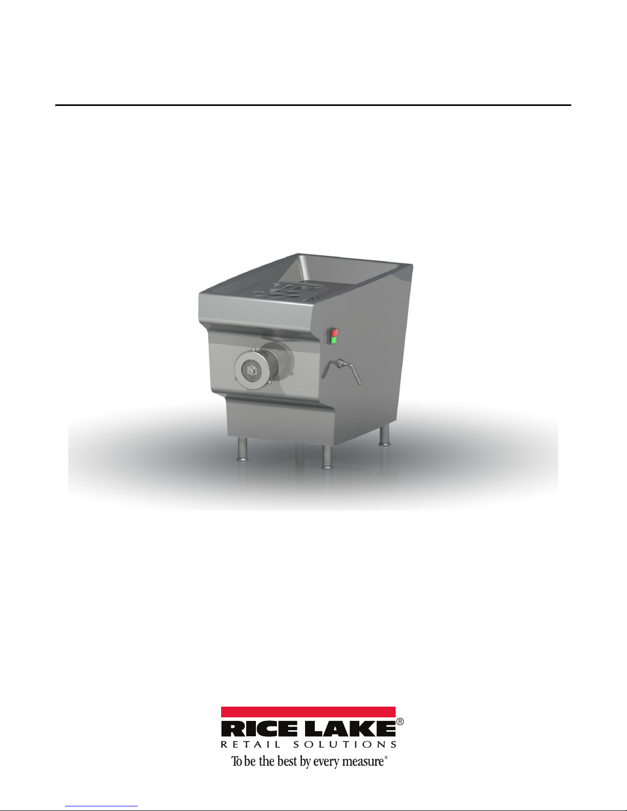
TX-22
Meat Grinder
Operation Manual
PN 159765
Page 2

Page 3

Contents
Technical training seminars are available through Rice Lake Weighing Systems.
Course descriptions and dates can be viewed at www.ricelake.com/training
or obtained by calling 715-234-9171 and asking for the training department.
1.0 Introduction..................................................................................................................................... 1
1.1 Safety . . . . . . . . . . . . . . . . . . . . . . . . . . . . . . . . . . . . . . . . . . . . . . . . . . . . . . . . . . . . . . . . . . . . . . . . . . 1
1.2 Delivery and Handling . . . . . . . . . . . . . . . . . . . . . . . . . . . . . . . . . . . . . . . . . . . . . . . . . . . . . . . . . . . . . . 1
1.3 Dimensions and Specifications . . . . . . . . . . . . . . . . . . . . . . . . . . . . . . . . . . . . . . . . . . . . . . . . . . . . . . . 2
2.0 Installation and Operation .............................................................................................................. 3
2.1 Unpacking and Installing the Meat Grinder. . . . . . . . . . . . . . . . . . . . . . . . . . . . . . . . . . . . . . . . . . . . . . . 3
2.2 Sound Specifications . . . . . . . . . . . . . . . . . . . . . . . . . . . . . . . . . . . . . . . . . . . . . . . . . . . . . . . . . . . . . . . 4
2.3 Optional Stand. . . . . . . . . . . . . . . . . . . . . . . . . . . . . . . . . . . . . . . . . . . . . . . . . . . . . . . . . . . . . . . . . . . . 4
2.4 Operation . . . . . . . . . . . . . . . . . . . . . . . . . . . . . . . . . . . . . . . . . . . . . . . . . . . . . . . . . . . . . . . . . . . . . . . 5
2.4.1 Grinding Meat . . . . . . . . . . . . . . . . . . . . . . . . . . . . . . . . . . . . . . . . . . . . . . . . . . . . . . . . . . . . . . . . . . . . . . 5
3.0 Parts ................................................................................................................................................ 6
4.0 Maintenance ................................................................................................................................. 10
4.1 Maintenance at Installation. . . . . . . . . . . . . . . . . . . . . . . . . . . . . . . . . . . . . . . . . . . . . . . . . . . . . . . . . . 10
4.2 Periodic Maintenance . . . . . . . . . . . . . . . . . . . . . . . . . . . . . . . . . . . . . . . . . . . . . . . . . . . . . . . . . . . . . 10
4.3 Cleaning . . . . . . . . . . . . . . . . . . . . . . . . . . . . . . . . . . . . . . . . . . . . . . . . . . . . . . . . . . . . . . . . . . . . . . . 10
4.4 Wiring Diagrams . . . . . . . . . . . . . . . . . . . . . . . . . . . . . . . . . . . . . . . . . . . . . . . . . . . . . . . . . . . . . . . . . 12
4.5 Troubleshooting Chart . . . . . . . . . . . . . . . . . . . . . . . . . . . . . . . . . . . . . . . . . . . . . . . . . . . . . . . . . . . . . 13
TX-22 Meat Grinder Limited Warranty...................................................................................................... 14
© Rice Lake Weighing Systems. All rights reserved. Printed in the United States of America.
Rice Lake Weighing Systems is an ISO 9001 registered company.
Brand Name: DADAUX GASTROTECH
Specifications subject to change without notice.
January 12, 2015
i
Page 4

ii TX-22 Meat Grinder Operation Manual
Rice Lake continually offers web-based video training on a growing selection
of product-related topics at no cost. Visit www.ricelakeretail.com/webinars.
Page 5
1.0 Introduction
Important
CAUTION
WARNING
DANGER
WARNING
Note
CAUTION
Authorized distributors and their employees can view or download this manual from the Rice Lake
Weighing Systems distributor site at
1. 1 S af et y
Safety Symbol Defintions:
Indicates an imminently hazardous situation that, if not avoided, will result in death or serious injury.
Indicates a potentially hazardous situation that, if not avoided, could result in serious injury or death, and
includes hazards that are exposed when guards are removed.
Indicates a potentially hazardous situation that, if not avoided, may result in minor or moderate injury.
Indicates information about procedures that, if not observed, could result in damage to equipment or
corruption to and loss of data.
Do not operate or work on this equipment unless you have read and understand the instructions and
warnings in this manual. Failure to follow the instructions or heed the warnings could result in injury or
death. Contact any Rice Lake Weighing Systems dealer for replacement manuals. Proper care is your
responsibility.
www.ricelake.com.
General Safety
Study the Following Safety Rules
Failure To Heed May Result In Serious Personal Injury Or Death.
FOLLOW setup instructions provided for proper installation.
NEVER touch this machine without training and authorization from your supervisor.
Machine MUST be on a solid level support.
Guards MUST be in place before plugging in
ALWAYS use the three (3) pronged grounded plug provided.
ALWAYS use the feed stomper - NOT your hand.
NEVER touch the rotating blades.
ALWAYS keep your fingers, hands and
ALWAYS turn OFF and UNPLUG machine before cleaning or servicing.
NEVER operate machine with objects NOT provided by the manufacturer.
and turning on machine.
clothing away from moving parts.
1.2 Delivery and Handling
Upon receipt of the shipping pallet, inspect it for any visible signs of damage and inspect the contents to ensure all
components are included.
The grinder is heavy. Use two people when unpacking, lifting or moving the unit.
Notify the carrier immediately if shipping carton is damaged. If equipment is damaged, notify the carrier
within five (5) days and save all documents.
Remove packaging carefully (see Section 2.1)
Introduction 1
Page 6

The TX-22 Meat Grinder is Delivered With Following Accessories
19.6 in
(497.3 mm)
16.9 in
(438.2 mm)
22.9 in
(581.5 mm)
15.2 in
(385.9 mm)
30 in
(762.8 mm)
28.8 in
(731.6 mm)
11.3 in
(285.5 mm)
8.1 in
(206.4 mm)
18.3 in
(464.1 mm)
13.8 in
(349.5 mm)
8.3 in
(211.4 mm)
Description Qty
Enterprise System Knife 1
Plate 22 with holes Ø 3/16 in (5 mm) 1
Body Nut 1
Extractor for Helical Screw 1
Feed Stomper 1
Table 1-1. Accessories Parts List
1. 3 Dimensions and Specifications
Technical Data
• Material: stainless steel with a sanded or brushed appearance, steel and polythene
• Weight: 159 lb (70 kg)
• Volume: 30 in x 19.6 in x 22.9 in (762.8 mm x 497.3 mm x 581.5 mm)
• Engine power: 0.75 Kw
• Hopper capacity: 4 gal (15.5 L)
• Exit diameter: 3.25 in (82 mm)
• Motor: single phase 115V or 230, 60Hz
• Waterproof monobloc crankcase AISI 304
• Auger body made of 100% stainless steel
Figure 1-1. Dimensions
2 TX-22 Meat Grinder
Page 7
2.0 Installation and Operation
CAUTION
Important
24 in
(600 mm)
8 in
(200 mm)
19.7 in
(500 mm)
2.1 Unpacking and Installing the Meat Grinder
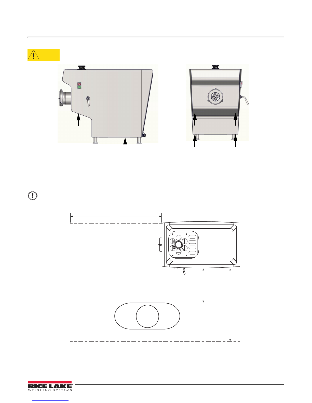
The grinder is heavy. Use two people when unpacking, lifting or moving the unit.
Figure 2-1. Remove Meat Grinder from Packaging
1. Carefully remove packing material from top and sides of machine.
2. With the assistance of another person, lift machine from the
locations shown in Figure 2-1.
3. Place grinder on a solid, level table or support.
The floor must be able to support the weight of the machine, 159 lb (70 kg).
The grinder should be placed in a well lit area and the space around
operator (see Figure 2-2).
carton by lifting from the bottom at the
the grinder must be sufficient for its
Figure 2-2. Necessary Space for the Operator to use the Grinder
4. Inspect machine for damage and proper guard placement.
5. Plug machine into a properly grounded outlet using t
will be specified on the machine serial number plate.
he plug supplied with the machine. The proper voltage
Installation and Operation 3
Page 8

6. Test the machine power by pressing the green ON button. The helical screw must turn in the direction of
Note
ON/OFF Button
Important
45"
17.2"
28.8"
23.3"
14.8"
18"
the arrow as indicated in Figure 2-3.
If the machine is not running correctly, turn off immediately and unplug. Contact your service agent.
7. Clean and sanitize machine before using (See Section 4.3).
.
Figure 2-3. Meat Grinder ON/OFF Button
If the grinder does not work properly, immediately press the red OFF button and contact customer service.
2.2 Sound Specifications
The airborne noise emitted by the grinder has a level lower than 70 dB.
2.3 Optional Stand
An optional stand is available (PN160270)
4 TX-22 Meat Grinder
Figure 2-4. Optional Stand
Page 9
2.4 Operation
WARNING
Cutting Body
Feed Screw
Body Nut
Monobloc Knife
Pilot Stud
Plate
Feed Stomper
ON/OFF Button
Guard Plate
Meat Chamber
Locking Body Handle
WARNING
The TX-22 Grinder has been designed and manufactured to continuously mince several different kinds of meat.
Never touch this machine without training and authorization from a supervisor.
ALWAYS turn OFF and UNPLUG machine before cleaning or servicing.
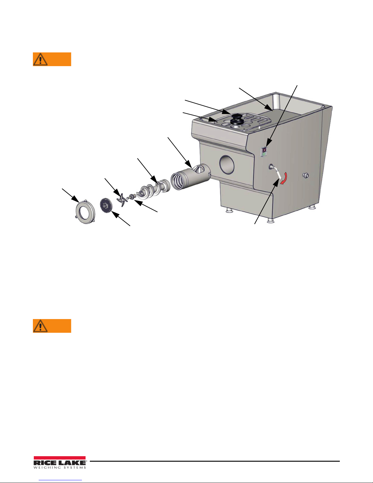
Before using the grinder, check that all components of the machine are in proper position.
Figure 2-5. Component Installation Order
• Cutting body placed on the grinder and tightened by the locking body handle.
• Helical screw inserted into the body and coupled with the tra
• System enterprise knife 22 mounted
onto the end part of the feed screw.
nsmission shaft.
• Hole plate 22 inserted ahead of the knife.
• Nut tightened ahead of the plate but not totally blocked (full tightening of the
the meat is inserted into the exit plate).
The grinder must not be used with grates with holes with a diameter larger than 8 mm. The thickness of
the grate must be 5 mm or more.
To handle the knife, the operator of the machine must wear cut-resist
Before the removal of the cutting elements (grate/kni
unplugged. It is strictly prohibited to use this machine in another configuration or purpose for which it
was intended.
fe/screw), the power supply plug must be
2.4.1 Grinding Meat
1. Put the meat to grind onto the tray.
2. Press the green
3. Insert the meat into the hole of the tray, use the pe
ON button to start the grinder.
stle to push the meat into the feeding hole.
4. Press the red OFF button to stop the grinder.
nut is only necessary when
ant gloves.
Installation and Operation 5
Page 10
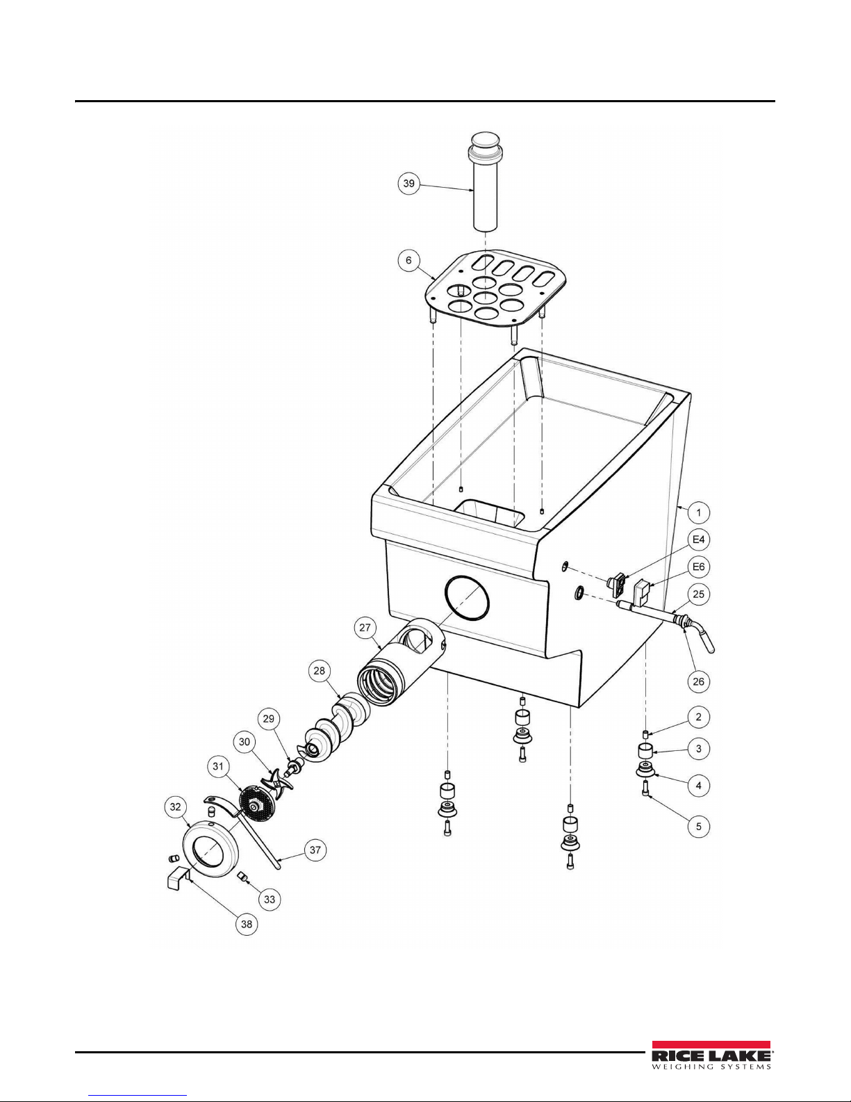
3.0 Parts
6 TX-22 Meat Grinder
Figure 3-1. TX-22 Meat Grinder Parts Diagram
Page 11
Item # Description Reference Qty
1 Frame Stainless Steel 304 1
2 Foot Cross Bar Tube Stainless Steel 304 4
3 Foot Tube Stainless Steel 304 4
4 Foot Connector EPDM 4
5 Cap Screw CHC, M8 - 25 Stainless Steel A2 4
6 Guard Plate Stainless Steel 304 1
25 Locking Body Handle Stainless Steel 304 1
26 Sheet Metal Guide for Lo
cking Body Handle Stainless Steel 304 1
27 Cutting Body Stainless Steel 304 1
28 Feed Screw Stainless Steel 304 1
29 Pilot Stud Feed Screw Stainless Steel X46 Cr13 1
30 Monobloc Knife 22 Stainless Steel 1
31 Cutting Plate 22 Holes Ø 4.5 in (114.3 mm) Stainless Steel 1
32 Body Nut Stainless Steel 304 1
33 Body Nut Axis Stainless Steel 304 3
37 Body Nut Key Stainless Steel 304 1
38 Extractor for Helical Screw Stainless Steel 304 1
39 Feed Stomper 1
E4 On/Off Switch Button ZB5 AW 833743 1
E6 Watertightness Cap For On/Off Switch Button ZBW 008A 1
Table 3-1. TX-22 Meat Grinder Parts List
Parts 7
Page 12
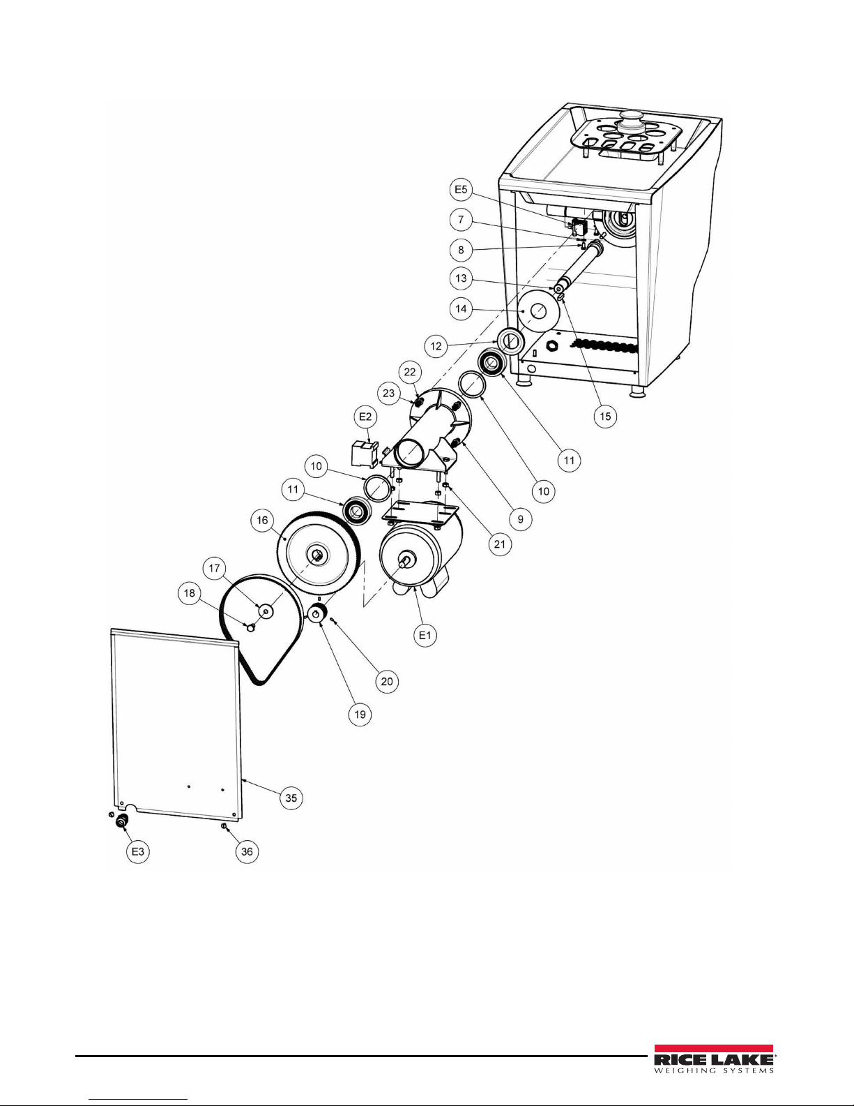
Figure 3-2. TX-22 Meat Grinder Parts Illustration (continued)
8 TX-22 Meat Grinder
Page 13
Item # Description Reference Qty
7 Flat Washer, D6 - D12 - E1,2 Stainless Steel A2 4
8 Hexagonal Headed Screw, M6 - 12 Stainless Steel A2 4
9 Transmission Shaft Bearing Stainless Steel 304 1
10 Bearing Support Ring Stainless Steel 304 2
11 Tough Ball Bearing, 6306 – 2rs1 Steel 2
12 Lipped Seal, BA 40 – 72 – 7 NBR 1
13 Transmission Shaft Stainless Steel 304 1
14 Deflector for Transmission Shaft Bearing Stainless Steel 304 1
15 Cotter Pulley Transmission Shaft, 8 X 7 Long 40 Stainless Steel 304 1
16 Pulley Htd 5m 136 – 25 EN AW-6082 1
17 Support Washer For Receiving Pulley, D10.2 - D38 - E3 Stainless Steel 304 1
18 Hexagonal Headed Screw, M10 -20 Stainless Steel A2 1
19 Pulley HTD 5M 26 – 25 With Brackets Steel 1
20 Grub Screw HC, M4 - 8 Stainless Steel A2 3
21 Hexagonal Nut, M8 Stainless Steel A2 8
22 Flat Washer, D8 - D16 - E1,5 Stainless Steel A2 4
23 Hexagonal Nut, M8 Stainless Steel A2 4
35 Rear Door Stainless Steel 304 1
36 Pan-Form Headed Screw, M5 - 10 Stainless Steel A2 2
E1 Helical Screw Motor 1HP 6P F56H 115/208-230V
1
60HZ IP21 B3R
E2 Contactor 110 V LC1 K1610 FE7 1
Contactor 220 V LC1 K0910 M7 1
E3 Stuffing Box Pg13,5 EPN 250 / PG13 9005 1
Check Nut Stuffing Box Pg13,5 EPN 355 / PG13 PS 9005 1
E5 Contact Block For On/off Switch Button ZB5 AW 0B15 1
E7 Flexible Power Cable Length 2 Meters (not shown) SJTOO 14AWG 1
E8 Power Plug Phase + Neutral + Earth (not shown) XN515P-A 1
Table 3-2. TX-22 Meat Grinder Parts List (continued)
Parts 9
Page 14

4.0 Maintenance
WARNING
WARNING
Body Nut
Key
Body Nut
Unscrew body nut
Place extractor on helical
screw
Pull extractor to remove
screw and cutting elements
Remove body
nut and plate
4.1 Maintenance at Installation
• Check the body and accessories condition.
• Check if the supply voltage is the same as the value indicated on
machine.
• Check the functioning of the helical screw (see Section 2.1).
4.2 Periodic Maintenance
When the installation and first use are done, keeping the high performance and reliability of the grinder requires
very little maintenance. However, it is necessary to check periodically the wear level of the knife 22.
Wear mesh gloves when handling the knife.
4.3 Cleaning
ALWAYS turn OFF and UNPLUG machine before cleaning or servicing.
A thorough cleaning to remove meat residue must be done daily and after each use.
Follow this procedure for the cleaning of the grinder:
1. Disconnect the power plug from the electrical outlet.
2. Remove the body nut, grate and cutting elements as shown
the model-identification nameplate of the
in Figure 4-1.
10 TX-22 Meat Grinder
Figure 4-1. Remove Parts for Cleaning
Page 15
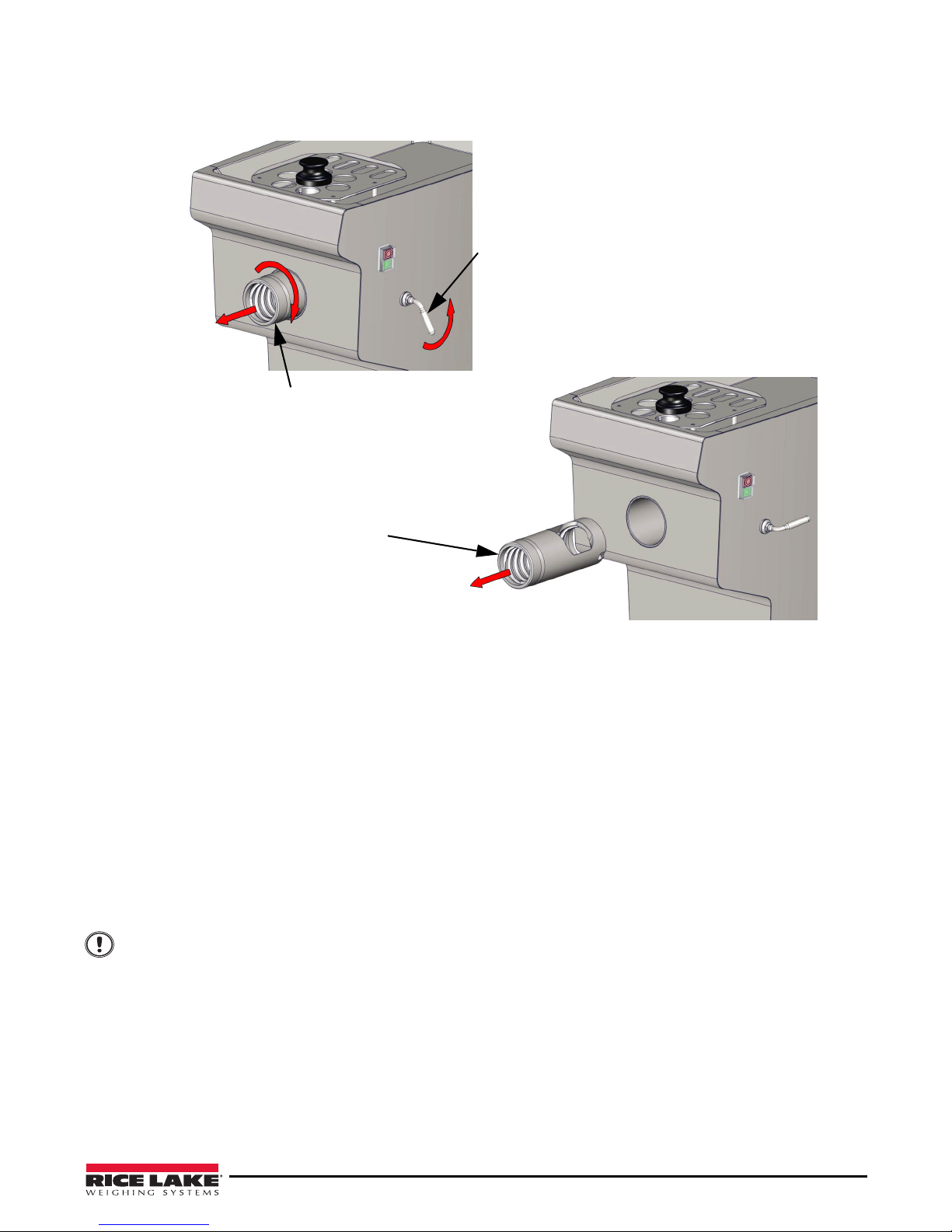
3. Remove the cutting body as shown in Figure 4-2.
Turn locking handle the
direction shown.
Turn cutting body the
direction shown.
Pull cutting body from
grinder.
Important
Figure 4-2. Remove Cutting Body
4. Soak all these parts and the feed stomper in water and clean them carefully.
5. Rinse the entire machine with clean water (hot or
6. Brush the machine with lukewarm water (40 to 50°C) and deter
cold) to remove all visible organic matter.
gent (basic phase) to remove dirt.
7. Rinse with clean water (hot or cold) to remove any trace of detergent and organic matter.
8. Disinfect and sanitize to destroy the germs.
9. Thoroughly rinse (hot or cold) to remove
10. Drain and let dry without wiping in order to avoid contamination of
all the resting sanitizing product.
the cleaned surface.
Other Cleaning Advice
• Use an acid detergent (acid phase) to dissolve mineral deposits (ie: scale deposit). Its use frequency
depends on the equipment, the product and the process undergone by the product.
• Rinse with clean water to remove any trac
Only use drinking water during cleaning operations.
Do not use a high pressure cl
Use detergent products compatible with INOX (STAIN
POLYETHYLENE 500 (PEhd 500)
The main disinfectant detergents used in food-processing sector are chlorinated alkaline detergents. RLWS
recommends the use of these products that are compatible with the materials used to manufacture the TX-22 Meat
Grinder.
e of acid product and mineral material.
eaning machine.
LESS STEEL) 304 (X5 Cr Ni 18-10) and
Maintenance 11
Page 16

4.4 Wiring Diagrams
S1 - Push red button to stop
S2 - Push green button to start
KM1 - Grinder Motor Switch
S1
S2
13
Km1.1
14
A2
A1
KM1
U1
V1
PE
N
L1
M
230 V
P = 0.75 Kw
In = 5.5 A
60Hz
GRINDER
MOTOR
KM1
S1
S2
13
Km1.1
14
A2
A1
KM1
U1
V1
PE
N
L1
M
115 V
P = 0.75 Kw
In = 11 A
60Hz
GRINDER
MOTOR
KM1
115V – 60Hz
230V – 60Hz
WARNING
Any changes to the electrical wiring must be carried out by qualified and trained personnel and must be
done only after having unplugged the machine from the power suppl
y.
12 TX-22 Meat Grinder
Figure 4-3. Wiring Diagrams
Page 17

4.5 Troubleshooting Chart
Issue Possible Cause Solutions
The helical screw does not work. Plug disconnected from electric supply outlet. Connect the plug to e
Electric component is defective. Please contact the after-sales service.
Rotation of the screw and the
e counterclockwise.
arm ar
The helical screw is blocked. Product stuck in the cutting body. Disconnect the plug from the electric
Product does not cut easily. System enterprise knife N° 22 used. Replace the knife with a new one.
Reverse connection. Please contact the after-sales service.
pply outlet. Unscrew the nut, extract the
su
cutting elements and then the screw to
remove the stuck product.
lectric supply outlet.
Maintenance 13
Page 18

TX-22 Meat Grinder Limited Warranty
Rice Lake Weighing Systems (RLWS) warrants that all RLWS equipment and systems properly installed by a
Distributor or Original Equipment Manufacturer (OEM) will operate per written specifications as confirmed by the
Distributor/OEM and accepted by RLWS. All systems and components are warranted against defects in materials
and workmanship for one year.
RLWS warrants that the equipment sold hereunder will conform to the current written specifications authorized by
RLWS. RLWS warrants the equipment against faulty workmanship and defective materials. If any equipment fails
to conform to these warranties, RLWS will, at its option, repair or replace such goods returned within the warranty
period subject to the following conditions:
• Upon discovery by Buyer of such nonconformity, RLWS will be given prompt written notice with a
detailed explanation of the alleged deficiencies.
• Individual electronic components returned to RLWS for warranty purposes must be packaged to prevent
electrostatic discharge (ESD) damage in shipment. Packaging requirements are listed in a publication,
Protecting Your Components From Static Damage in Shipment, available from RLWS Equipment Return
Department.
• Examination of such equipment by RLWS confirms that the nonconformity actually exists, and was not
caused by accident, misuse, neglect, alteration, improper installation, improper repair or improper testing;
RLWS shall be the sole judge of all alleged non-conformities.
• Such equipment has not been modified, altered, or changed by any person other than RLWS or its duly
authorized repair agents.
• RLWS will have a reasonable time to repair or replace the defective equipment. Buyer is responsible for
shipping charges both ways.
• In no event will RLWS be responsible for travel time or on-location repairs, including assembly or
disassembly of equipment, nor will RLWS be liable for the cost of any repairs made by others.
THESE WARRANTIES EXCLUDE ALL OTHER WARRANTIES, EXPRESSED OR IMPLIED, INCLUDING WITHOUT
LIMITATION WARRANTIES OF MERCHANTABILITY OR FITNESS FOR A PARTICULAR PURPOSE. NEITHER RLWS
NOR DISTRIBUTOR WILL, IN ANY EVENT, BE LIABLE FOR INCIDENTAL OR CONSEQUENTIAL DAMAGES.
RLWS AND BUYER AGREE THAT RLWS’ SOLE AND EXCLUSIVE LIABILITY HEREUNDER IS LIMITED TO REPAIR
OR REPLACEMENT OF SUCH GOODS. IN ACCEPTING THIS WARRANTY, THE BUYER WAIVES ANY AND ALL OTHER
CLAIMS TO WARRANTY.
SHOULD THE SELLER BE OTHER THAN RLWS, THE BUYER AGREES TO LOOK ONLY TO THE SELLER FOR
WARRANTY CLAIMS.
NO TERMS, CONDITIONS, UNDERSTANDING, OR AGREEMENTS PURPORTING TO MODIFY THE TERMS OF THIS
WARRANTY SHALL HAVE ANY LEGAL EFFECT UNLESS MADE IN WRITING AND SIGNED BY A CORPORATE
OFFICER OF RLWS AND THE BUYER.
© Rice Lake Weighing Systems, Inc. Rice Lake, WI USA. All Rights Reserved.
RICE LAKE WEIGHING SYSTEMS • 230 WEST COLEMAN STREET • RICE LAKE, WISCONSIN 54868 • USA
14 TX-22 Meat Grinder
Page 19

Page 20

230 W. Coleman St. • Rice Lake, WI 54868 • USA
U.S. 800-472-6703 • Canada/Mexico 800-321-6703 • International 715-234-9171 • Europe +31 (0)26 472 1319
www.ricelake.com www.ricelake.mx www.ricelake.eu www.ricelake.co.in m.ricelake.com
© Rice Lake Weighing Systems 01/12/2015 PN 159765
 Loading...