

Page 1

THERMAL PRINTER
TSP700 Series
TECHNICAL MANUAL
[
FIRST
EDITION
]
Page 2

NOTICE
• All rights reserved. Reproduction of any part of this manual in any
form whatsoever, without STAR’s express permission is forbidden.
• The contents of this manual are subject to change without notice.
• All efforts have been made to ensure the accuracy of the contents
of this manual at the time of going to press. However, should any
errors be detected, STAR would greatly appreciate being informed of them.
• The above notwithstanding, STAR can assume no responsibility
for any errors in this manual.
© Copyright 2001Star Micronics Co.,Ltd.
Page 3

INTRODUCTION
This manual describes the thermal printer TSP700 series.
It is designed for use as a reference for periodic inspections and maintenance procedures to be executed
by service personnel. It is not intended for the general user. Users of this manual should have a basic
knowledge and understanding of the English language.
• This manual is divided into the following sections:
Chapter 1 Parts Replacement and Adjustments
Chapter 2 Maintenance and Lubrication
Chapter 3 Parts List
• First edition : Mar. 2001
1
2
3
Page 4

Page 5

CHAPTER 1
PARTS REPLACEMENT
This chapter explains disassembly and reassembly of the printer. Note the following precautions during
disassembly and reassembly.
1. Disconnect the printer power cord plug from the wall outlet before servicing it.
2. Assembly is the reverse of disassembly unless otherwise specified.
3. After reassembly, coat the screw heads with locking sealant.
4. Lubrication information is not provided in this chapter. Refer to item 2 of chapter 2.
5. The printer has no adjustable parts.
1. Lower Case Unit ....................................................................................................3
2. Upper Case Unit ....................................................................................................3
3. Board Chassis Unit ...............................................................................................4
4. Main Logic Board ..................................................................................................4
1
5. Platen Unit..............................................................................................................5
6. Paper Feed Motor ..................................................................................................5
Page 6

Page 7
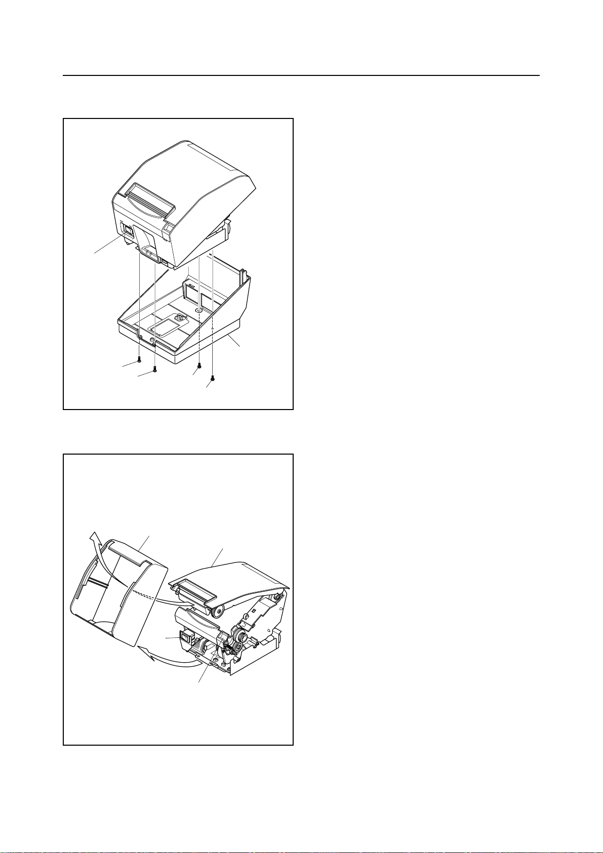
PARTS REPLACEMENT
1. Lower Case Unit
(1) Turn off the power switch 1, disconnect the power
cord from the wall outlet.
(2) Remove
• Two tapping screws 2
• Two tapping screws 3
• Lower case unit 4
1
4
2
2
3
3
2. Upper Case Unit
(1) Turn off the power switch1, disconnect the power
cord from the wall outlet.
4
3
1
(2) Remove the lower case unit according to the
procedure described in item 1.
(3) Push the cover open lever 2, and open the printer
cover 3.
(4) Remove the upper case unit 4.
2
– 3 –
Page 8
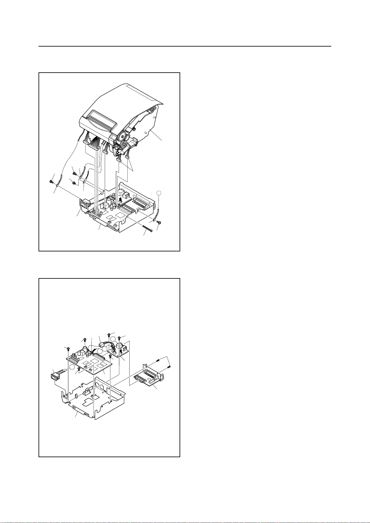
PARTS REPLACEMENT
2
2
5
3
3. Board Chassis Unit
(1) Turn off the power switch1, disconnect the power
cord from the wall outlet.
(2) Remove
• Upper case according to the procedure described
in item 2.
7
6
• Three screws 2
• Screw 3
• Screw 4
• Three wires 5
• Six connectors 6
• Printer mechanism 7
• Board chassis unit 8
5
5
1
8
A
5
2
4
4. Main Logic Board
(1) Turn off the power switch, disconnect the power
coard from the wall outlet.
3
4
4
3
3
5
A
3
A
B
7
3
B
1
3
6
2
(2) Remove
• Board chassis unit according to the procedure
described in item 3.
• Two screws 1
• Interface board unit 2
• Six screws 3
• Two connectors 4
• Power switch 5
• Sub-board 6
• Main logic board 7
• Board chassis 8
8
– 4 –
Page 9
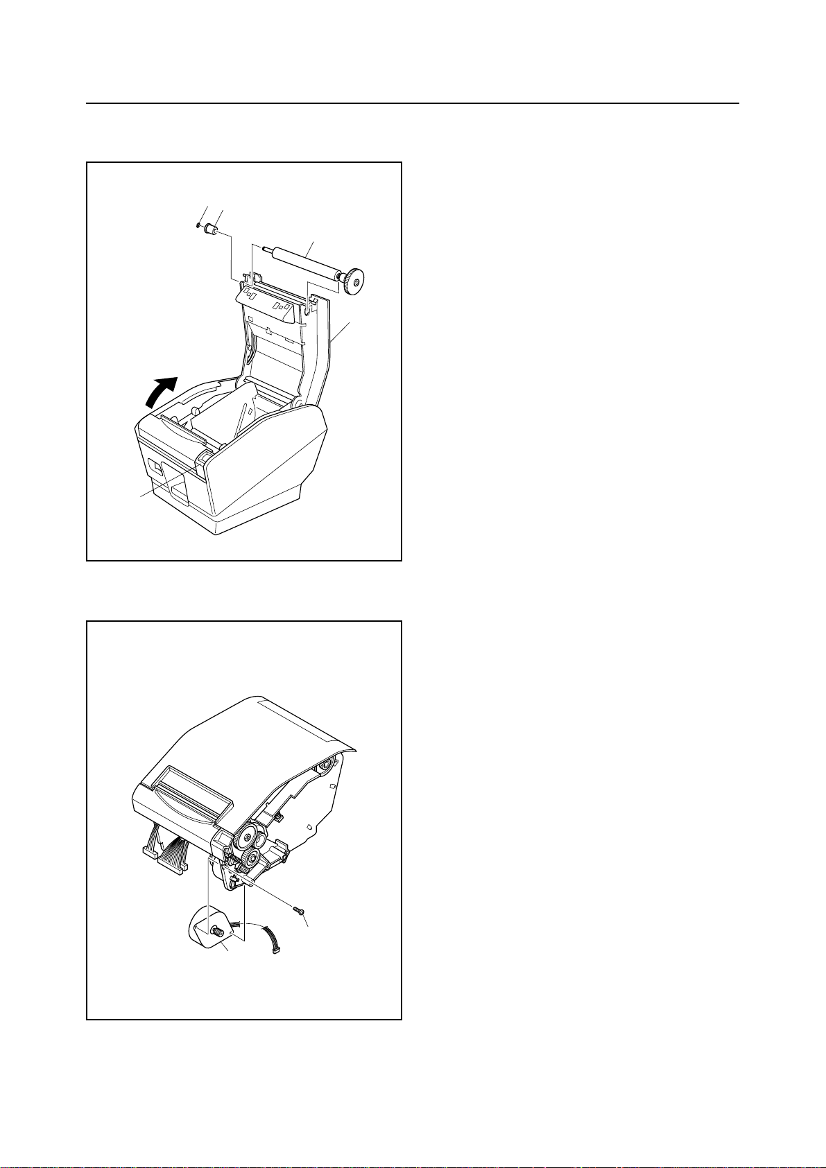
PARTS REPLACEMENT
5. Platen Unit
3
4
5
(1) Turn off the power switch, disconnect the power
cord from the wall outlet.
(2) Push the cover open lever 1, and open the printer
cover 2.
2
(3) Remove
• Stop ring 3
• Bearing 4
• Platen unit 5
1
6. Paper Feed Motor
(1) Turn off the power switch, disconnect the power
cord from the wall outlet.
(2) Remove
• Printer mechanism according to the procedure
described in item 3.
• Screw 1
• Paper feed motor unit 2
1
2
– 5 –
Page 10

Page 11

CHAPTER 2
MAINTENANCE AND LUBRICATION
1. Maintenance...........................................................................................................9
1-1. Cleaning .................................................................................................................. 9
1-2. Checks ..................................................................................................................... 9
2. Lubrication...........................................................................................................10
2-1. Type of oil.............................................................................................................. 10
2-2. Lubrication method .............................................................................................. 10
2-3. Lubrication locations ........................................................................................... 10
1
2
Page 12

Page 13

MAINTENANCE AND LUBRICATION
1. Maintenance
Carry out maintenance control items listed below to maintain the original performance of this printer and prevent trouble
from occurring.
1-1. Cleaning
(1) Removal of dirt.
Clean the dirt with tissure or soft cloth.
Note: Do not use thinners or trichlene/ketone base solvents for cleaning as they can damage plastic parts.
Be careful not to damage electrical parts, wired areas or mechanisms and avoid getting them wet.
(2) Removal of dust, pile, etc.
Clean with a vacuum cleaner.
Note: Check the amount of oil after cleaning and lubricate if necessary.
1-2. Checks
Maintenance checks for this printer is divided into the two areas of “daily check” that the person using the printer carries
out during normal use and “regular check” that can be done only by an experienced person with a knowledge of the
equipment.
(1) Daily check:
Check that the printer is being properly used.
• Is the peper set correctly?
• Is there any dirt or foreign object in the printer?
(2) Regular check:
Carry out regular check and lubrication after six months use or after printing 1 million lines.
• Check for bending of springs.
• Remove any dirt or dust in the area of the detectors.
– 9 –
Page 14

MAINTENANCE AND LUBRICATION
2. Lubrication
Lubrication is extremely important for preserving the original performance of the printer over a long period of time.
2-1. Type of oil
The type of oil used has a major influence on the performance and durability of the printer.You should pay particular
attention to the cold temperature properties of the oil. We recommend use of the grease and lubrication oils listed below
for this printer.
Type of oil Product name Manufacturer
Grease Molykote EM-30L Dow Corning Corp.
2-2. Lubrication method
When lubricating during disassembly or assembly operations, be sure to wash and clean the equipment well prior to
lubrication to remove dirt and dust.
Lubricate the equipment at regular intervals of six months or after every one million lines. Be sure to lubricate equipment
after disassembling or replacing parts when oil has been removed by cleaning.
2-3. Lubrication locations
Lubrication locations Type of oil
1 Rubbing surface of Shaft C and Frame Molykote EM-30L
2 Rubbing surface of Case stopper and Screw and Frame Molykote EM-30L
3 Rubbing surface of Gear 24 × 0.7 - 55 × 0.5 and Frame shaft Molykote EM-30L
4 Rubbing surface of Gear 40 × 0.5 and Freme shaft Molykote EM-30L
5 Rubbing surface of Cover B assy and Lock lever Molykote EM-30L
6 Rubbing surface of Lock lever and Cover open lever Molykote EM-30L
7 Rubbing surface of Release plate and Cover B assy Molykote EM-30L
8 Rubbing surface of Release plate and Lock plate Molykote EM-30L
9 Rubbing surface of Lock plate and Cover B assy Molykote EM-30L
0 Rubbing surface of Lock plate and Lock plate spring Molykote EM-30L
A Rubbing surface of detector holder and near-end detector cover Molykote EM-30L
– 10 –
Page 15

8
0
9
MAINTENANCE AND LUBRICATION
G
F
E
D
F
2
7
A
B
A
C
1
5
6
1
G
1
C
2
C
D
E
A
3
Fig. 2-1 Lubricated Area
– 11 –
4
B
C
3
Page 16

Page 17

CHAPTER 3 PARTS LIST
HOW TO USE PARTS LIST
(1) DRWG. NO.
This column shows the drawing number of the illustration.
(2) REVISED EDITION MARK
This column shows a revision number.
(3) PART NO.
Parts numbers must be notified when ordering replacement parts. Parts described as “NPN” have no parts
number and are not in stock, i.e., unavailable.
(4) PARTS NAME
Parts names must be notified when ordering replacement parts.
(5) Q’TY
This column shows the number of the part used as indicated in the figure.
(6) REMARKS
When differences in specifications exist depending on location/destination.
(7) RANK
Parts marked “S” a service parts. Service parts are recommended to be in stock for maintenance.
3
3-1. Printer Assembly................................................................................................ 14
3-1-1. Disassembly Drawing...........................................................................................14
3-1-2. Parts List ............................................................................................................... 15
3-2. Printer Mechanism ............................................................................................. 16
3-2-1. Disassembly Drawing...........................................................................................16
3-2-2. Parts List ............................................................................................................... 17
3-3. Sub-Assembly .................................................................................................... 19
3-3-1. Cover Open Lever Unit.........................................................................................19
3-3-2. Head Unit ...............................................................................................................20
3-4. Block Diagram .................................................................................................... 21
3-5. Main Logic Board ............................................................................................... 22
3-5-1. Circuit Diagram .....................................................................................................22
3-5-2. Parts List ...............................................................................................................27
3-6. Sub-Board........................................................................................................... 30
3-6-1. Circuit Diagram .....................................................................................................30
3-6-2. Parts List ...............................................................................................................30
3-7. Serial Interface Board (25pin) ........................................................................... 31
3-7-1. Circuit Diagram .....................................................................................................31
3-7-2. Parts List ...............................................................................................................32
3-8. Serial Interface Board (9pin) ............................................................................. 33
3-8-1. Circuit Diagram .....................................................................................................33
3-8-2. Parts List ...............................................................................................................34
3-9. USB Interface Board .......................................................................................... 35
3-9-1. Circuit Diagram .....................................................................................................35
3-9-2. Parts List ...............................................................................................................36
10
. Parallel Interface Board ..................................................................................... 37
3-
3-10-1.Circuit Diagram ..................................................................................................... 37
3-10-2.Parts List ...............................................................................................................38
Page 18

3-1. Printer Assembly
3-1-1. Disassembly Drawing
7
15
6
3
C
E
F
11
E
F
15
C
D
11
B
11
A
11
2
11
11
B
A
16
15
5
D
9
12
12
11
4
14
14
– 14 –
15
10
11
11
8
1
17
18
Page 19

3-1-2. Parts List
Printer Assembly
DRWG.NO. REV. PARTS NO. PARTS NAME Q'TY REMARKS RANK
1 37450030 LOWER CASE UNIT TSP7 1
2 NPN BOARD CHASSIS TSP7 1
3 30970040 THERMAL ROLL PAPER 80X35D 1
4 37457020 MAIN LOGIC BOARD UNIT TSP7 1
5 37457210 SUB-BOARD UNIT TSP7 1
6 38440000 TMP743-24 1 S
7 37451030 UPPER CASE UNIT TSP7 1
8 39607200 INTERFACE BOARD IFBD-HD03 1 OPTION:SERIAL 25 PIN
39607300 INTERFACE BOARD IFBD-HN03 1 OPTION:SERIAL 9 PIN
39607220 INTERFACE BOARD IFBD-HU03 1 OPTION:SERIAL USB
39607210 INTERFACE BOARD IFBD-HC03 1 OPTION:PARALLEL IF
9 30781180 ADAPTER SET PS60-24A JP 1 OPTION
30781190 ADAPTER SET PS60-24A US 1 OPTION
30781200 ADAPTER SET PS60-24A EU 1 OPTION
30781210 ADAPTER SET PS60-24A UK 1 OPTION
30781220 ADAPTER SET PS60-24A AS 1 OPTION
10 NPN SWITCH COVER TSP8 1
11 01903101 SCREW TAT 3-6 CT-FL 9
12 00930609 SCREW TAT 3-6 CT 2
14 01903047 SCREW TAT 3-12 PT-FL 2
15 01903060 SCREW TAT 3-8 PT-FL 4
16 01903093 SCREW TR 3-25 1
17 NPN FERRITE CORE K5BRC24X14X11 1 PARALLEL IF
18 04991204 FASTENER T18S 1 PARALLEL
IF
– 15 –
Page 20

3-2. Printer Mechanism
3-2-1. Disassembly Drawing
53
55
G
F
E
D
3
F
60
50
52
60
50
39
13
50
10
C
32
27
D
41
52
A
E
31
27
B
C1
26
31
52
30
50
C2
A
40
50
18
51
65
42
35
59
5
28
55
66
21
42
24
62
50
2
9
4
43
17
37
G
64
36
6
38
22
7
8
14
58
63
23
45
49
57
56
50
1
19
61
15
29
54
20
48
20
25
47
54
44
27
11
B
44
12
24
62
68
67
33
16
43
18
59
C3
– 16 –
Page 21

3-2-2. Parts List
Printer Mechanism
DRWG.NO. REV. PARTS NO. PARTS NAME Q'TY REMARKS RANK
1 NPN WIRE 26UL1007BLK060TT 1
2 33215020 BEARING TMP8 1 S
3 NPN COVER A TMP7 1
4 30903040 CUTTER UNIT ORC-RSY90 1 S
5 NPN PAPER GUIDE B TMP7 1
6 NPN PAPER GUIDE A TMP7 1
7 NPN PE DETECTOR COVER UNIT TMP8 1
8 NPN PE DETECTOR UNIT TMP8 1
9 37463110 PLATEN UNIT TMP7 1 S
10 NPN RELEASE PLATE TMP8 1
11 33102250 GEAR 24X0.7-55X0.5 TMP8 1
12 33102260 GEAR 40X0.5 TMP8 1
13 NPN SHAFT B TMP7 1
14 NPN LOCK LEVER TMP8 1
15 NPN HEAD HOLDER PLATE UNIT TMP7 1
16 NPN OIL DAMPER 058E-F 1
17 NPN SHAFT C TMP7 2
18 NPN TENSION SHAFT HOLDER TMP7 2
19 NPN CASE STOPPER TMP8 1
20 NPN GROUND PLATE A TMP8 2
21 NPN CUTTER PLATE TMP7 1
22 NPN FRAME UNIT TMP7 1
23 NPN TENSION SHAFT TMP7 1
24 NPN PUSH LEVER TMP8 2
25 37462001 PF MOTOR UNIT TMP8 1 S
26 NPN NEAR-END DETECTOR COVER TMP7 1
27 37467310 NEAR-END DETECTOR ASSY TMP7 1
28 NPN COVER OPEN LEVER UNIT TMP7 1
29 37469010 HEAD UNIT TMP7 1
30 NPN COVER B ASSY TMP7 1
31 NPN LOCK PLATE TMP8 1
32 NPN LOCK PLATE SPRING TMP7 1
33 NPN GEAR 14X40X0.8 TMP8 1
34 NPN SHAFT LEVER TMP7 1
35 NPN DETECTOR LEVER TMP7 1
36 NPN HEAD LEVER R TMP7 1
37 NPN HEAD LEVER L TMP7 1
38 33910350 ROLL PAPER GUIDE TMP7 1
39 NPN DETECTOR HOLDER TMP7 1
40 NPN LOCK PLATE SPRING TMP8 1
41 01902032 SCREW TAT 2-10 PT 1
42 00820304 SCREW TR 2-3 2
43 01902028 SCREW TAT 2-4 3
44 00920603 SCREW TAT 2-6 PT 2
45 01903077 SCREW TAT 3-5 CT-FL 1
47 00630504 SCREW TR 3-5 1
48 00930609 SCREW TAT 3-6 CT 1
49 00930603 SCREW TAT 3-6 PT 1
50 01903061 SCREW TAT 3-6 PT-FL 10
51 00930803 SCREW TAT 3-8 PT 2
52 04020010 STOP RING SE2.0 3
53 04020015 STOP RING SE3.0 1
54 NPN CLAMP SPRING TMP8 2
55 04991204 FASTENER T18S 3
56 NPN FERRITE CORE BP53-19-12-8 1
57 82200010 COLLAR 822 1
– 17 –
Page 22

Printer Mechanism
DRWG.NO. REV. PARTS NO. PARTS NAME Q'TY REMARKS RANK
58 NPN SPRING E043-035-0164 1
59 NPN SPRING E050-032-0141 2
60 NPN SPRING C068-050-0065 2
61 NPN SPRING C075-060-0300 1
62 NPN SPRING C075-070-0238 2
63 NPN CAUTION SEAL TMP8 1
64 NPN PAPER SET SEAL TMP8 1
65 NPN WIRE 18UL1007BLK245TT 1
66 30903030 STATIONARY KNIFE ORC-RSY90 1 S
67 02841000 CUT WASHER 4.1X6.5X0.5 1
68 02852000 CUT WASHER 5.2X8.0X0.5 1
– 18 –
Page 23

3-3. Sub-Assembly
3-3-1. Cover Open Lever Unit
28
-
4
2
3
5
6
2
DRWG.NO. REV. PARTS NO. PARTS NAME Q'TY REMARKS RANK
28-1 NPN SCREW TAT 2-4 1
28-2 NPN STOP RING SE2.0 2
28-3 NPN SPRING E038-030-0142 1
28-4 NPN SHAFT A TMP7 1
28-5 NPN LEVER PLATE TMP8 1
28-6 NPN COVER OPEN LEVER TMP8 1
1
– 19 –
Page 24

3-3-2. Head Unit
29
-
1
5
2
7
6
2
8
9
3
4
1
DRWG.NO. REV. PARTS NO. PARTS NAME Q'TY REMARKS RANK
29-1 00926403 SCREW TAT 2.6-4 CT 2
29-2 01903030 SCREW TR 3-4 FL 2
29-3 NPN HEAD EARTH PLATE TMP7 1
29-4 NPN WIRE 18UL1007BRN145TT 1
29-5 30905050 THERMAL HEAD AE080-H8E801 1 S
29-6 31210000 COLLAR TMP8 1
29-7 NPN HEAD PLATE TMP7 1
29-8 30721500 CABLE UNIT 15X175CC TMP7 1
29-9 NPN FERRITE CORE K5BRC16X16X8-M 1
– 20 –
Page 25

3-4. Block Diagram
– 21 –
Page 26

3-5. Main Logic Board
3-5-1. Circuit Diagram
– 22 –
Main Logic Board ( 1/5)
Page 27

– 23 –
Main Logic Board ( 2/5)
Page 28

– 24 –
Main Logic Board ( 3/5)
Page 29

– 25 –
Main Logic Board ( 4/5)
Page 30

– 26 –
Main Logic Board ( 5/5)
Page 31

3-5-2. Parts List
Main Logic Board
DRWG.NO. REV. PARTS NO. PARTS NAME Q'TY REMARKS RANK
C01 NPN CERA.CAPA.CHIP1608 0.22UF 10V 1
C02 NOT MOUNTED
C03-06 NPN CERA.CAPA.CHIP1608 0.022UF 50V 4
C07-09 NOT MOUNTED
C11-19 NOT MOUNTED
C21-22 NOT MOUNTED
C31-32 NOT MOUNTED
C33 NPN CHEM. CAPA. 47UF 35V 1
C34-35 NOT MOUNTED
C36 NPN CERA.CAPA.CHIP1608 3900PF 50V 1
C41 NOT MOUNTED
C42-43 NPN CERA.CAPA.CHIP1608 0.1UF 25V 2
C44 NOT MOUNTED
C45 NPN CERA.CAPA.CHIP1608 0.022UF 50V 1
C51 NPN FILM CAPA. 0.1UF 50V 1
C52 NPN CERA.CAPA.CHIP1608 0.01UF 50V 1
C53-54 NOT MOUNTED
C55 NPN CHEM. CAPA. 470UF 10V 1
C56 NPN CHEM. CAPA. 1000UF 35V 1
C61 NPN CERA.CAPA.CHIP1608 0.1UF 25V 1
BC01-03 NPN CERA.CAPA.CHIP1608 0.022UF 50V 3
BC04-07 NPN CERA.CAPA.CHIP1608 0.1UF 25V 4
BC08A NPN CERA.CAPA.CHIP1608 0.022UF 50V 1
BC08B NPN CHEM. CAPA. 47UF 35V 1
BC09 NPN CHEM. CAPA. 47UF 35V 1
BC10 NPN CERA.CAPA.CHIP1608 0.022UF 50V 1
BC12 NOT MOUNTED
CN01 NPN CONNECTOR B14B-PH-K-S 1
CN02 NPN CONNECTOR B15B-PH-K-S 1
CN03 NPN CONNECTOR 53014-0412 1
CN04 NPN CONNECTOR PHEC40R-R111 1
CN05 NPN CONNECTOR 5483-05A 1
CN06 NPN CONNECTOR 53014-0510 1
CN08 NPN CONNECTOR 53014-0310 1
CN09 NPN CONNECTOR 53014-0410 1
CN10 NOT MOUNTED
CN11 NPN CONNECTOR 53520-0220 1
D1-4 NPN SCHOTTKY DIODE CHIP D1FS4* 4
D5-6 NPN DIODE CHIP D1F20-4063* 2
DSW1 NPN DIP SWITCH 210B008MS 1
DSW2 NPN DIP SWITCH 210B004MS 1
FB01-05 NPN CHIP BEADS IND. BK1608HS601* 5
FB06-07 NOT MOUNTED
FB08 NPN CHIP BEADS IND. BK1608HS601* 1
FB09-10 NPN CHIP BEADS IND. BK2125HS470* 2
IC01 NPN IC-RESET M51953BFP*E2 1
IC02 NPN CPU HD6412350F20 1
IC03 NPN GATE ARRAY LZ9FG28-TSPA 1
IC04 NPN FLASH MEMORY 28F400BVE-85 1 T7 **
IC05 NPN FLASH MEMORY 28F400BVE-85 1 T7#SD *.*
IC06-07 NPN SRAM 431000AGZ-70LL* 2
IC08 NPN IC-MOTOR MTD2003F-4072 1
IC09 NPN IC-MOTOR TA8428K 1
IC10 NPN IC-LIN UPC393G2*T1 1
IC11 NPN IC-REG SI-8401L 1
IC12 NOT MOUNTED
– 27 –
Page 32

Main Logic Board
DRWG.NO. REV. PARTS NO. PARTS NAME Q'TY REMARKS RANK
JP1A NPN CHIP RESISTOR 0 OHM 1/16W 1
JP1B NOT MOUNTED
JP2 NOT MOUNTED
LED1-2 NPN LED CHIP LT1E40A* 2
LED3 NPN LED CHIP LT1D40A* 1
R101 NPN CHIP RESISTOR 1.5 KOHM 1/16W 1
R102 NPN CHIP RESISTOR 10 K-OHM 1/16W 1
R103 NPN CHIP RESISTOR 2.2 K-OHM 1/16W 1
R104 NPN CHIP RESISTOR 22 K-OHM 1/16W 1
R105 NPN CHIP RESISTOR 1 K-OHM 1/16W 1
R106 NPN CHIP RESISTOR 470 OHM 1/16W 1
R107 NPN CHIP RESISTOR 1 K-OHM 1/16W 1
R108 NPN CHIP RESISTOR 470 OHM 1/16W 1
R109 NPN CHIP RESISTOR 100 OHM 1/16W 1
R116-119 NPN CHIP RESISTOR 10 K-OHM 1/16W 4
R120-121 NOT MOUNTED
R122-124 NPN CHIP RESISTOR 10 K-OHM 1/16W 3
R125 NOT MOUNTED
R126-127 NPN CHIP RESISTOR 10 K-OHM 1/16W 2
R128-130 NPN CHIP RESISTOR 330 OHM 1/16W 3
R131-134 NOT MOUNTED
R135 NPN CHIP RESISTOR 4.7 K-OHM 1/16W 1
R136-138 NPN CHIP RESISTOR 10 K-OHM 1/16W 3
R139 NPN CHIP RESISTOR 1 K-OHM 1/16W 1
R140-141 NPN CHIP RESISTOR 10 K-OHM 1/16W 2
R142-145 NPN CHIP RESISTOR 330 OHM 1/16W 4
R146 NPN CHIP RESISTOR 220 OHM 1/16W 1
R147 NOT MOUNTED
R148-153 NPN CHIP RESISTOR 330 OHM 1/16W 6
R154-158 NPN CHIP RESISTOR 10 K-OHM 1/16W 5
R159-161 NPN CHIP RESISTOR 100 K-OHM 1/16W 3
R163-164 NPN CHIP RESISTOR 100 K-OHM 1/16W 2
R165 NPN CHIP RESISTOR 470 OHM 1/10W 1
R166-170 NPN CHIP RESISTOR 100 K-OHM 1/16W 5
R171-176 NOT MOUNTED
R177 NPN CHIP RESISTOR 0 OHM 1/16W 1
R178 NPN CHIP RESISTOR 100 OHM 1/16W 1
R179 NPN CHIP RESISTOR 0 OHM 1/16W 1
R180 NPN CHIP RESISTOR 100 OHM 1/16W 1
R181-185 NOT MOUNTED
R201-203 NPN CHIP RESISTOR 10 K-OHM 1/16W 3
R204-206 NPN CHIP RESISTOR 1 K-OHM 1/16W 3
R207 NPN CHIP RESISTOR 330 OHM 1/16W 1
R208 NPN CHIP RESISTOR 1 K-OHM 1/16W 1
R209 NPN CHIP RESISTOR 15 K-OHM 1/16W 1
R210 NPN CHIP RESISTOR 10 K-OHM 1/16W 1
R211-212 NPN CHIP RESISTOR 10 K-OHM 1/10W 2
R213-216 NPN CHIP RESISTOR 10 K-OHM 1/16W 4
R217 NPN CHIP RESISTOR 330 OHM 1/16W 1
R218-220 NPN CHIP RESISTOR 1 K-OHM 1/16W 3
R221-222 NPN CHIP RESISTOR 330 OHM 1/16W 2
R223-226 NPN CHIP RESISTOR 10 K-OHM 1/16W 4
R227-230 NPN CHIP RESISTOR 100 OHM 1/16W 4
R231-234 NPN CHIP RESISTOR 10 K-OHM 1/16W 4
R235 NPN CHIP RESISTOR 15 K-OHM 1/16W 1
R236-237 NPN CHIP RESISTOR 1.0 OHM 1W 2
– 28 –
Page 33

Main Logic Board
DRWG.NO. REV. PARTS NO. PARTS NAME Q'TY REMARKS RANK
R301-305 NPN CHIP RESISTOR 100 K-OHM 1/16W 5
R306 NOT MOUNTED
R307-308 NPN CHIP RESISTOR 100 K-OHM 1/16W 2
R310 NOT MOUNTED
R311-312 NPN CHIP RESISTOR 330 OHM 1/16W 2
R313-314 NPN CHIP RESISTOR 10 K-OHM 1/16W 2
R315 NPN CHIP RESISTOR 4.7 K-OHM 1/16W 1
R316 NPN CHIP RESISTOR 10 K-OHM 1/16W 1
R317 NPN CHIP RESISTOR 4.7 K-OHM 1/16W 1
R318-319 NPN CHIP RESISTOR 10 K-OHM 1/16W 2
R320 NPN CHIP RESISTOR 4.7 K-OHM 1/16W 1
R321 NPN CHIP RESISTOR 10 K-OHM 1/16W 1
R322 NOT MOUNTED
R323 NPN CHIP RESISTOR 330 OHM 1/10W 1
R324 NPN CHIP RESISTOR 4.7 K-OHM 1/16W 1
R325-326 NPN CHIP RESISTOR 10 K-OHM 1/16W 2
R327-328 NPN CHIP RESISTOR 4.7 K-OHM 1/16W 2
R329 NOT MOUNTED
R330 NPN CHIP RESISTOR 330 OHM 1/10W 1
R401-402 NPN CHIP RESISTOR 1 K-OHM 1/16W 2
R403-404 NPN CHIP RESISTOR 330 OHM 1/16W 2
R405 NPN CHIP RESISTOR 4.7 K-OHM 1/16W 1
R406 NPN CHIP RESISTOR 33 K-OHM 1/16W 1
R407 NPN CHIP RESISTOR 10 K-OHM 1/10W 1
R408-410 NOT MOUNTED
R411-413 NPN CHIP RESISTOR 4.7 K-OHM 1/16W 3
R414-416 NPN CHIP RESISTOR 10 K-OHM 1/16W 3
R417-418 NPN CHIP RESISTOR 470 OHM 1/10W 2
R451-453 NPN CHIP RESISTOR 330 OHM 1/16W 3
R454 NPN CHIP RESISTOR 15 K-OHM 1/16W 1
R455 NPN CHIP RESISTOR 10 K-OHM 1/16W 1
R456 NPN CHIP RESISTOR 2.2 K-OHM 1/16W 1
RA01-04 NPN RESIS. ARRAY CHIP MNR14J221* 4
RA05-09 NPN RESIS. ARRAY CHIP MNR14J331* 5
REG1 NPN IC-REG UPC7824 1
SW1 NPN PUSH SWITCH SKHHAL 1
TR01 NPN CHIP TRANSISTOR 2SA1362GR*85R 1
TR02 NPN CHIP TRANSISTOR 2SC3875S-G*AL 1
TR03 NPN CHIP TRANSISTOR 2SA1649Z* 1
TR04 NPN CHIP TRANSISTOR 2SA1338-67*TA 1
TR05-07 NPN DIGITAL TRANSISTOR FA1A4P 3
TR08-09 07320101 TRANSISTOR 2SD2010 2
TR10 NPN CHIP TRANSISTOR 2SC3875S-G*AL 1
TR11 NPN CHIP TRANSISTOR 2SA1362GR*85R 1
TR12 NPN DIGITAL TRANSISTOR FA1A4P 1
VR1-2 NPN RP RESISTOR RH0615C-47K 2
XTAL NPN CERA. OSCILLATOR EFOMC2005T4* 1
ZD1 NPN ZENER DIODE CHIP HZU20B2TRF 1
ZD2 NPN ZENER DIODE RD7.5EB1T 1
– 29 –
Page 34

3-6. Sub-Board
3-6-1. Circuit Diagram
3-6-2. Parts List
Sub-Board
DRWG.NO. REV. PARTS NO. PARTS NAME Q'TY REMARKS RANK
C1-2 NOT MOUNTED
CN21 NPN CONNECTOR TCS7960-53-2010 1
CN22 NPN CONNECTOR 52065-6645 1
CN23 NPN CABLE UNIT 2X60CC TSP8 1
CN24 NPN CABLE UNIT 4X60CC TSP8 1
CN25 NPN CABLE UNIT 2X125C TSP8 1
F1 09991026 FUSE MRT3.15A-250V* 1
L1-2 NPN JUMPER WIRE 1/6W-L3.2 2
- NPN SEESAW SWITCH SF-W1H1A14BB 1
NPN HEAT-SHRINK TUBE F2-3.0 2
– 30 –
Page 35

3-7. Serial Interface Board (25 pin
3-7-1. Circuit Diagram
)
– 31 –
Page 36

3-7-2. Parts List
Serial Interface Board (25 pin)
DRWG.NO. REV. PARTS NO. PARTS NAME Q'TY REMARKS RANK
C1 NPN CHEM. CAPA. 1UF 50V 1
C2 NPN CERA.CAPA.CHIP1608 0.022UF 50V 1
C3-6 NPN CHEM. CAPA. 1UF 50V 4
C7-8 NPN CERA.CAPA.CHIP1608 0.022UF 50V 2
C9 NPN CERA.CAPA.CHIP1608 0.1UF 25V 1
CN1 NPN CONNECTOR PHEC40P-R111 1
CN2 NPN CONNECTOR DBLD-J25SAF-21L9-1 1
D1-2 NPN DIODE CHIP MC2840 2
D3 NPN DIODE CHIP MC2836 1
D4-5 NOT MOUNTED
DSW1 NPN DIP SWITCH 210B008MS 1
IC1 08200201 IC-I/F ST232CWR* 1 S
IC2 NPN IC-LIN UPC393G2*T1 1
L1-7 NPN CHIP BEADS IND. BK1608HS601* 7
L8 NPN CHIP RESISTOR 0 OHM 1/16W 1
L9 NOT MOUNTED
R1-2 NPN CHIP RESISTOR 10 K-OHM 1/16W 2
R3-4 NPN CHIP RESISTOR 100 OHM 1/16W 2
R5-6 NPN CHIP RESISTOR 10 K-OHM 1/10W 2
R7 NPN CHIP RESISTOR 4.7 K-OHM 1/16W 1
R8 NPN CHIP RESISTOR 10 K-OHM 1/16W 1
R9 NPN CHIP RESISTOR 10 K-OHM 1/10W 1
R10 NPN CHIP RESISTOR 100 K-OHM 1/16W 1
R11-12 NPN CHIP RESISTOR 10 K-OHM 1/16W 2
R13 NPN CHIP RESISTOR 100 K-OHM 1/16W 1
R14-15 NPN CHIP RESISTOR 100 OHM 1/16W 2
R16 NPN CHIP RESISTOR 10 K-OHM 1/16W 1
R17 NPN CHIP RESISTOR 10 K-OHM 1/10W 1
R18 NPN CHIP RESISTOR 2.7 KOHM 1/16W 1
R19-20 NPN CHIP RESISTOR 10 K-OHM 1/10W 2
R21 NPN CHIP RESISTOR 10 K-OHM 1/16W 1
R22 NPN CHIP RESISTOR 1 K-OHM 1/16W 1
R23 NPN CHIP RESISTOR 33 K-OHM 1/10W 1
R24 NPN CHIP RESISTOR 3.3 K-OHM 1/10W 1
RA1 NPN RESIS. ARRAY 10 K-OHM 1/8W 8EL 1
TR1 NPN CHIP TRANSISTOR 2SC3875S-G*AL 1
TR2 NPN CHIP TRANSISTOR 2SA1179M6-STR 1
TR3 NPN DIGITAL TRANSISTOR FN1A4P 1
TR4 NPN DIGITAL TRANSISTOR FA1A4P 1
TR5 NPN DIGITAL TRANSISTOR FN1A4P 1
TR6 NPN DIGITAL TRANSISTOR FA1A4P 1
– 32 –
Page 37

3-8. Serial Interface Board (9 pin
3-8-1. Circuit Diagram
)
– 33 –
Page 38

3-8-2. Parts List
Serial Interface Board (9 pin)
DRWG.NO. REV. PARTS NO. PARTS NAME Q'TY REMARKS RANK
C1 NPN CHEM. CAPA. 1UF 50V 1
C2 NPN CERA.CAPA.CHIP1608 0.022UF 50V 1
C3-6 NPN CERA.CAPA.CHIP1608 0.1UF 25V 4
C26-35 NOT MOUNTED
R1-2 NPN CHIP RESISTOR 10 K-OHM 1/16W 2
R4-5 NPN CHIP RESISTOR 10 K-OHM 1/16W 2
R6-7 NOT MOUNTED
R8 NPN CHIP RESISTOR 0 OHM 1/16W 1
R11-13 NPN CHIP RESISTOR 10 K-OHM 1/16W 3
RA1 NPN RESIS. ARRAY 10 K-OHM 1/8W 8EL 1
IC1 08200203 IC-I/F SP208ECA/TR* 1 S
IC2-3 NOT MOUNTED
IC4 NPN CMOS TC7WU04FU*12L 1
L1-7 NPN CHIP BEADS IND. BK1608HS601* 7
L8-9 NOT MOUNTED
DSW1 NPN DIP SWITCH 210B008MS 1
CN1 NPN CONNECTOR PHEC40P-R111 1
CN2 NPN CONNECTOR 17LE-23090-27D41 1
CN3 NOT MOUNTED
– 34 –
Page 39

3-9. USB Interface Board
3-9-1. Circuit Diagram
– 35 –
Page 40

3-9-2. Parts List
USB Interface Board
DRWG.NO. REV. PARTS NO. PARTS NAME Q'TY REMARKS RANK
BC1 NPN CERA.CAPA.CHIP1608 0.022UF 50V 1
BC2A-2C NPN CERA.CAPA.CHIP1608 0.022UF 50V 3
BC3 NPN CERA.CAPA.CHIP1608 0.1UF 25V 1
BC4-5 NPN CERA.CAPA.CHIP1608 0.022UF 50V 2
C01 NPN CERA.CAPA.CHIP1608 0.22UF 10V 1
C02 NPN CERA.CAPA.CHIP1608 0.022UF 50V 1
C03 NPN CHEM. CAPA. CHIP 4.7UF 35V 1
C04 NPN TANTALUM CAPA. CHIP 2.2UF 16V 1
C05 NPN CERA.CAPA.CHIP1608 0.1UF 25V 1
C06 NPN CERA.CAPA.CHIP1608 33PF 50V 1
C07 NPN CERA.CAPA.CHIP1608 680PF 50V 1
C08 NPN CERA.CAPA.CHIP1608 0.1UF 25V 1
C09-10 NOT MOUNTED
C11 NPN CERA. CAPA. CHIP 51PF 50V 1
CN1 NPN CONNECTOR PHEC40P-R111 1
CN2 NPN CONNECTOR V23590-T3111 1
IC1 NPN IC-RESET M51953BFP*E2 1
IC2 NPN CPU M37640MS-***FP 1
IC3 NPN IC SOCKET IC160-0324-300 1
NPN EPROM A276308AL-70 1
IC4 NPN CMOS 74LV02AFP*EL 1
IC5 NPN CMOS 74LV573AFP*EL 1
IC6 NPN CMOS 74LV1G04ACME* 1
L1-10 NPN CHIP RESISTOR 0 OHM 1/10W 10
RA01-02 NPN RESIS. ARRAY CHIP MNR14J101* 2
RA03-04 NOT MOUNTED
RA05 NPN RESIS. ARRAY CHIP MNR14J101* 1
R01 NPN CHIP RESISTOR 1.5 KOHM 1/16W 1
R02-09 NPN CHIP RESISTOR 100 OHM 1/16W 8
R10-11 NOT MOUNTED
R12 NPN CHIP RESISTOR 10 K-OHM 1/16W 1
R13 NOT MOUNTED
R14 NPN CHIP RESISTOR 1.5 KOHM 1/16W 1
R15-16 NPN CHIP RES3216 33 OHM 1/8W 1% 2
R17 NPN CHIP RESISTOR 1 K-OHM 1/16W 1
R18-19 NPN CHIP RESISTOR 10 K-OHM 1/16W 2
R20 NPN CHIP RESISTOR 330 OHM 1/16W 1
R21 NPN CHIP RESISTOR 100 OHM 1/16W 1
R22-26 NPN CHIP RESISTOR 10 K-OHM 1/16W 5
R27 NPN CHIP RESISTOR 330 OHM 1/16W 1
TR1 NPN DIGITAL TRANSISTOR FN1A4P 1
TR2 NPN DIGITAL TRANSISTOR FA1A4P 1
ZD1 NPN ZENER DIODE CHIP NNCD5.6LG*T1 1
XTAL NPN CERA. OSC CHIP EFJC2405E5B* 1
– 36 –
Page 41

3-10.
Parallel Interface Board
3-10-1. Circuit Diagram
– 37 –
Page 42

3-10-2. Parts List
Parallel Interface Board
DRWG.NO. REV. PARTS NO. PARTS NAME Q'TY REMARKS RANK
BC1-3 NPN CERA.CAPA.CHIP1608 0.022UF 50V 3
C1 NOT MOUNTED
C2 NPN CERA.CAPA.CHIP1608 1000PF 50V 1
C3-4 NOT MOUNTED
C5 NPN CHEM. CAPA. 1UF 50V 1
CN1 NPN CONNECTOR PHEC40P-R111 1
CN2 NPN CONNECTOR 57RE40360-730BD29 1
IC1 08211030 TTL IC HD74LS374FP*EL 1 S
IC2 NPN TTL IC 74ALS32FP*EL 1
IC3 08210126 TTL IC 74LS05FP*EL 1 S
L1-2 NPN CHIP RESISTOR 0 OHM 1/16W 2
L3-4 NOT MOUNTED
L5 09990754 CHIP BEADS IND. BK1608HS601* 1 S
L6 NOT MOUNTED
L7 NPN CHIP RESISTOR 0 OHM 1/16W 1
L8-10 NPN CHIP BEADS IND. BK2125HS470* 3
R1 NPN CHIP RESISTOR 10 K-OHM 1/16W 1
R2-9 NPN CHIP RESISTOR 4.7 K-OHM 1/16W 8
R10 NPN CHIP RESISTOR 1 K-OHM 1/16W 1
R11 NPN CHIP RESISTOR 4.7 K-OHM 1/16W 1
R12 NPN CHIP RESISTOR 1 K-OHM 1/16W 1
R13 NPN CHIP RESISTOR 100 OHM 1/16W 1
R14 NPN CHIP RESISTOR 4.7 K-OHM 1/16W 1
R15 NPN CHIP RESISTOR 1 K-OHM 1/16W 1
R16 NPN CHIP RESISTOR 4.7 K-OHM 1/16W 1
R17 NOT MOUNTED
R18 NPN CHIP RESISTOR 1 K-OHM 1/16W 1
R19-20 NPN CHIP RESISTOR 4.7 K-OHM 1/16W 2
R21 NPN CHIP RESISTOR 1 K-OHM 1/16W 1
R22 NPN CHIP RESISTOR 4.7 K-OHM 1/16W 1
R23 NPN CHIP RES1608 3.9 KOHM 1/16W 5% 1
R24 NPN CHIP RESISTOR 2.2 K-OHM 1/16W 1
R25 NPN CHIP RESISTOR 330 OHM 1/16W 1
RA1 NPN RESIS. ARRAY 4.7K-OHM 1/8W 8EL 1
RA2 NPN RESIS. ARRAY 1.8K-OHM 1/8W 5EL 1
TR1 NPN CHIP TRANSISTOR 2SC3875S-G*AL 1
– 38 –
Page 43

ELECTRONIC PRODUCTS DIVISION
STAR MICRONICS CO., LTD.
536 Nanatsushinya,
Shimizu, Shizuoka, 424-0066 Japan
Tel : 0543-47-0112
Fax:0543-48-5013
OVERSEAS SUBSIDIARY COMPANIES
STAR MICRONICS AMERICA, INC.
1150 King Georges Post Road, Edison,
NJ 08837-3729 U.S.A.
Tel : 732-623-5555
Fax: 732-623-5590
Please access the following URL
http://www.star-micronics.co.jp/service/frame_sp_spr_e.htm
for the lastest revision of the manual.
Distributed by
STAR MICRONICS U.K. LTD.
Star House, Peregrine Business
Park, Gomm Road, High Wycombe,
Bucks, HP13 7DL, U.K.
Tel : 01494-471111
Fax:01494-473333
2001.03.30
Printed in Japan, 80873295
 Loading...