

Page 1
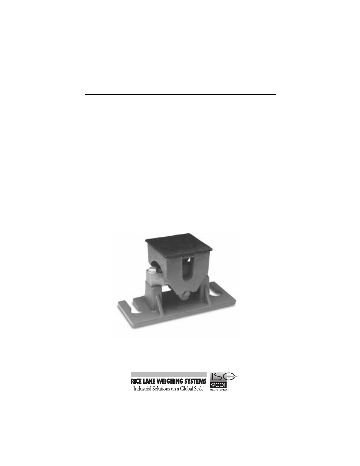
TSA
Truck Scale Weigh Module Kit
Installation
Guide
25709
Page 2

Contents
1. Introduction ........................................................................... 1
2. Mechanical Installation ......................................................... 2
2.1 General Installation Guidelines ..................................................2
2.2 Maintaining Scale Height and Center .........................................4
2.3 Mount and Load Procedures ......................................................4
2.31 Installing the Components ..............................................4
2.32 Leveling the Base and Securing the Girder Chair...........5
2.33 Re-leveling and Securing the Base.................................5
2.34 Replacing the Load Cell..................................................6
3. Load Cell Wiring.................................................................... 7
4. Junction Box Connections, Adjustments & Calibration.... 8
5. Troubleshooting .................................................................... 8
6. Maintenance and Replacement Parts................................ 10
6.1 Maintenance.............................................................................10
6.2 Replacement Parts...................................................................10
7. Appendix—Mount Dimensions .......................................... 11
8. Limited Warranty................................................................. 12
3/97
Page 3
1. Introduction
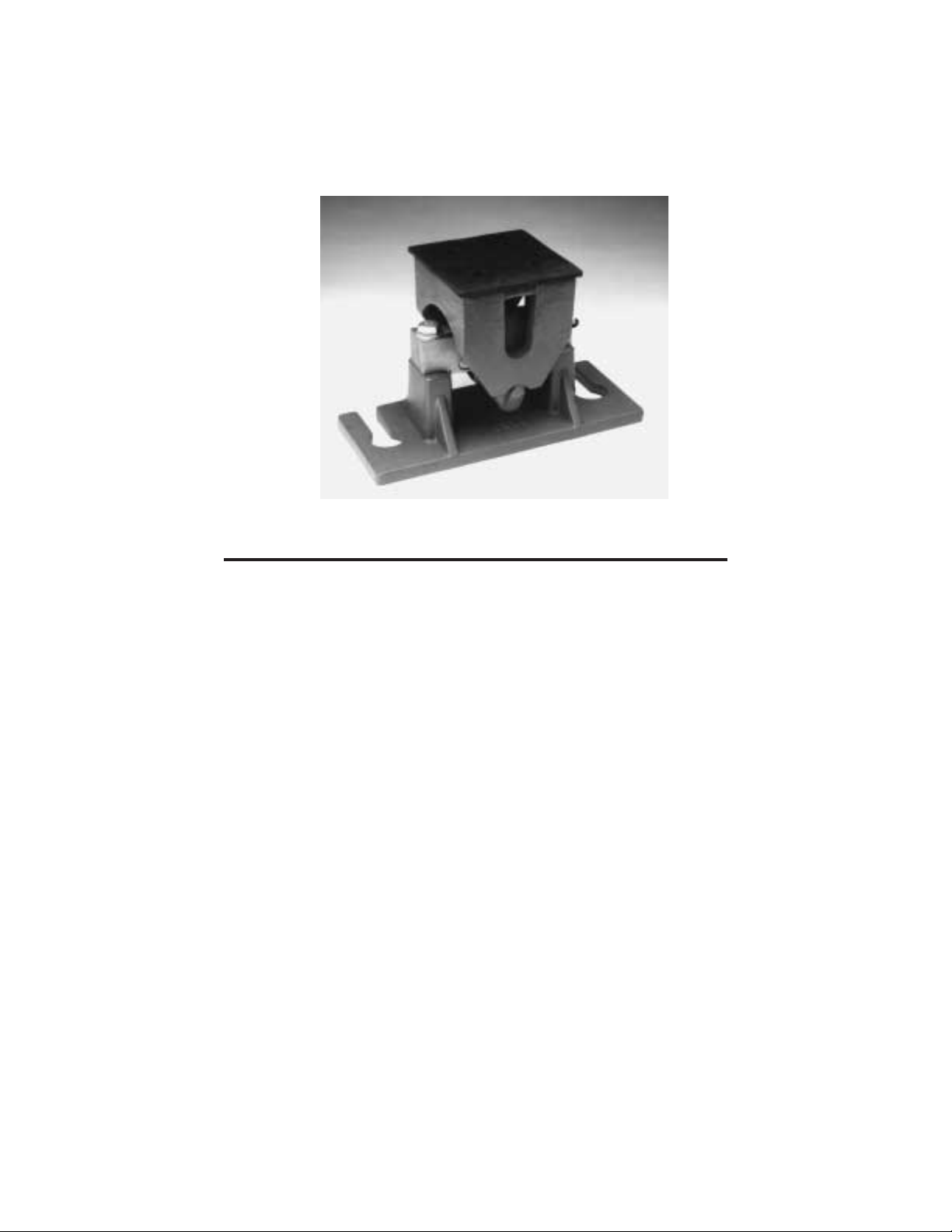
The TSA load cell mount is used for medium to heavy capacity truck, horizontal
vessel, and general purpose weighing applications. The mounts are constructed of
cast steel and iron, and are available in two sizes with capacities of 10,000 lb to
75,000 lb. In most applications, the need for safety check rods, expansion assemblies and other peripheral hardware is eliminated by the "Unilink" suspension
design and the load equalizer pad. These design elements provide self-checking and
improved weight distribution.
The TSA mounts use the Sensortronics 65058 double-ended shear beam load cell,
which is made of high alloy tool steel, environmentally protected, and rated for a
150% maximum overload.
1
Page 4
2. Mechanical Installation
2.1 General Installation Guidelines
• Install a system ground in the pit close to the junction box. Use at least 1/2” x
8’ copper clad ground rod. Hook the indicator, junction box, Scale deck I-beam,
load cell grounding straps, and lightning protection devices to the system
ground. Hook all other devices, such as the printer, to the same AC power
supply as the indicator.
• If the pit fills up with water, proper drainage must be provided so that the
weighing assembly is not standing in water. Also, drip loops should be
provided on any conduit or cables going to the junction box or load cell.
• If safety check rods are necessary, consult your supervising engineer for proper
placement and stability. If bumper bolts are necessary, install them between the
scale platform and the walls of the pit. Leave about 1/8" clearance or as
applicable.
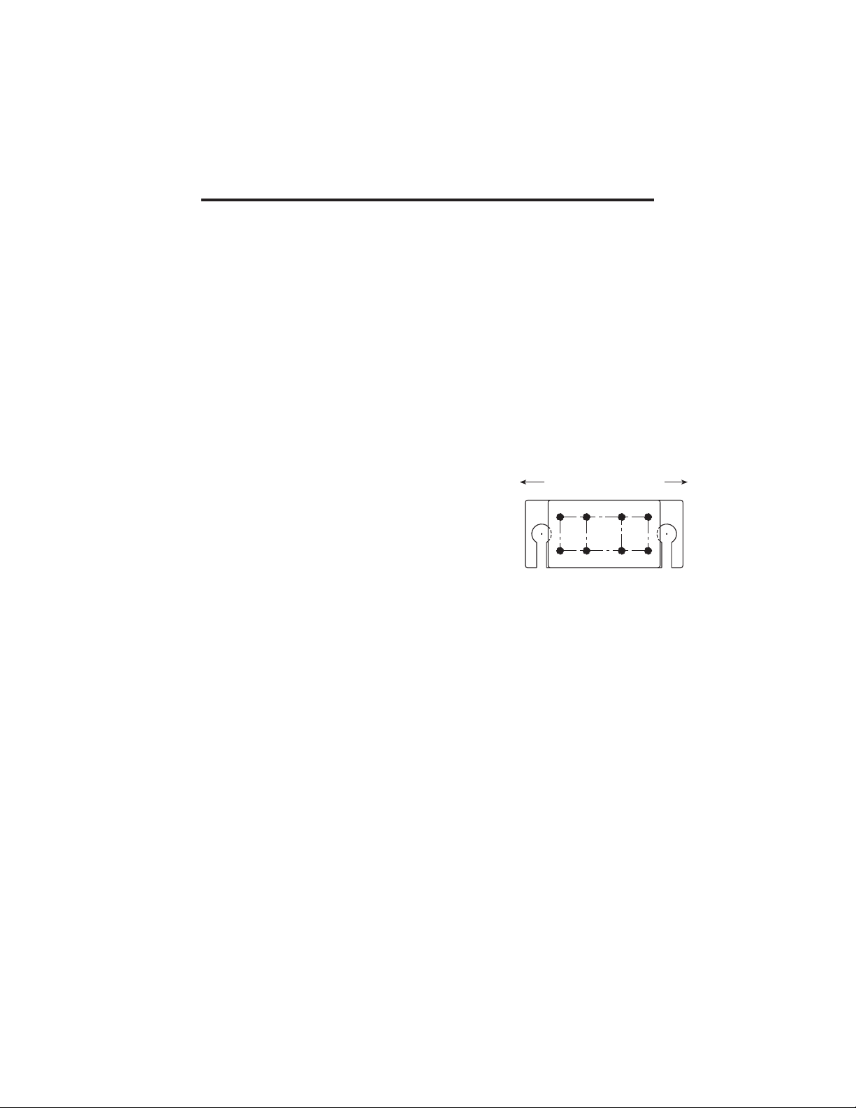
• The mount must be positioned in the direction of
travel. Also the load on each mount assembly should
be equal to each other.
• The mounting surface for the base and loading plate
must be level and parallel so that side loads and
bending moments are minimized. The mount assemblies must be plumb and level within ±0.2°.
• Because the load cell could be damaged during installation, do not use
excessive force or slam parts on the load cell. Also, when any welding is
required on the mount, remove the load cell from the mount so it is not damaged
by welding currents or excessive heat.
Direction of Travel
2
Page 5
a
a
a
a
a
a
a
aa
a
aa
aaa
a
a
a
a
a
a
a
aa
a
a
aa
a
a
a
a
a
aa
aa
a
a
a
a
aa
a
a
a
a
a
a
a
a
a
a
a
a
a
a
a
aa
a
a
a
a
a
a
a
a
a
a
a
a
a
a
a
a
a
a
a
a
a
a
a
a
a
a
aa
a
a
a
a
a
a
a
a
a
a
a
a
a
a
a
a
a
a
a
a
a
a
a
a
a
a
a
a
aa
a
aa
a
a
a
a
a
aaa
a
aa
a
a
a
a
aa
a
a
a
a
a
a
a
a
a
a
a
a
a
aa
aa
a
a
aa
a
a
a
a
a
a
a
a
a
aa
a
a
aa
a
a
aaa
a
a
a
a
a
a
a
a
a
a
a
a
a
a
a
a
a
a
a
a
a
a
a
a
a
a
a
a
a
a
a
a
a
a
a
a
a
a
a
a
a
a
a
a
a
a
a
a
a
a
a
a
a
a
a
a
a
a
a
a
a
a
a
a
a
a
a
a
a
a
a
a
aa
a
a
a
a
a
a
a
aa
a
a
a
a
a
a
a
a
a
aa
a
a
a
a
a
a
a
a
a
a
a
a
a
a
a
a
a
a
a
a
aaa
a
a
a
a
a
a
a
a
a
a
a
a
a
a
a
a
a
a
a
aa
a
a
aa
a
aa
a
a
a
a
a
a
a
a
aa
a
a
a
a
a
a
a
a
a
a
a
a
a
a
a
a
a
a
a
a
a
a
a
a
a
a
a
a
a
a
a
a
a
a
a
a
a
a
a
a
a
a
a
a
a
a
a
a
a
a
a
a
a
a
a
a
a
a
a
a
a
a
a
a
a
a
a
a
a
a
a
a
a
a
a
a
a
a
a
a
a
a
a
a
a
a
a
a
a
a
a
aa
a
aa
a
a
a
a
a
a
a
a
aa
a
a
a
a
a
a
a
a
a
a
a
a
a
a
a
a
a
a
a
a
a
a
a
aa
a
a
a
a
a
a
a
a
a
a
a
a
a
a
a
a
aa
a
a
a
aa
a
a
a
aa
a
aaa
aa
a
a
a
a
a
a
a
a
a
a
a
a
a
a
a
a
a
a
aaa
a
a
a
a
a
aa
a
a
a
a
a
a
a
a
a
a
a
a
aa
a
a
a
a
a
a
a
a
a
a
a
a
a
aa
a
a
a
a
a
a
aa
a
a
a
a
a
a
a
a
a
a
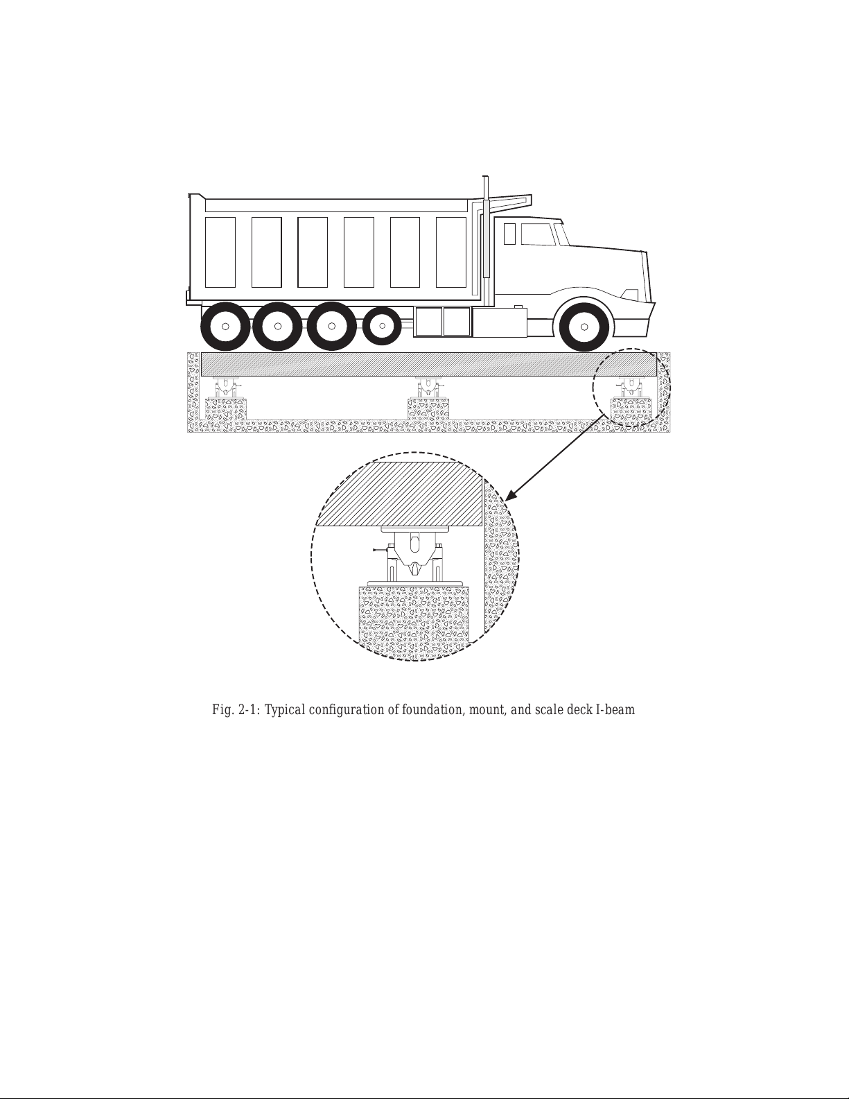
Fig. 2-1: Typical configuration of foundation, mount, and scale deck I-beam
3
Page 6

2.2 Maintaining Scale Height and Center
Whether you are replacing existing scales or installing new load cell mounts, you
will need to maintain the final height of your scale system.
1. On the concrete pier foundations, install blocking to hold up the scale deck
I-beam and platform to the required height for normal truck scale operation. Place wedges between the platform and the pit’s edges to center the
platform.
2. Remove the existing scales and/or install the new mounts one at a time to
continue to maintain the proper height. Installation procedures follow this
section.
2.3 Mount and Load Procedures
2.31 Installing the Components
Caution
!
When placing parts on the load cell, be careful not to drop or slam parts on the load
cell. Damage to the load cell will make the scale inoperable.
1. Start with a flat, rigid foundation
(concrete pier). Position the base
stand onto the foundation. Align
the base stand in the direction of
travel (Fig. 2.1, p. 3).
2. Place the load cell onto the two
stands of the base stand and screw
in the load cell mounting bolts (finger snug tight). The loose bolts
allow the TSA freer movement for
better weighing accuracy.
3. Place the load link on top of the
load cell, the girder chair on top of
the load link, and the rubber pad on
top of the girder chair. (In a multiple cell (more than 4) application,
do something different with the
rubber pads.)
4. Adjust the load link so it is vertical
and centered side to side (in a balanced condition). If the load link is
not vertical and centered side to
side, adjust the base stand.
Rubber
Pad
Girder Chair
Load Link
Load Cell
Base Stand
Fig. 2-2: Component assembly
4
Page 7

2.32 Leveling the Base and Securing the Girder Chair
Leveling is the single most important part of the installation for achieving highaccuracy weighing.
1. Check to see whether the girder chair is centered longitudinally with the
scale deck I-beam, and adjust the mount if necessary. Place shims between
the top of the girder chair and the bottom of the scale deck I-beam, because
the scale deck I-beam is never even. The shims should cover the entire
surface to prevent bending.
2. Using a high-quality bubble level, level the base stand within 0.2° of
horizontal to achieve a scale accuracy of 0.1% or better. The base stand
should be parallel with the girder chair, and the link plumb.
3. Mark the girder chair hole locations on the scale deck I-beam (see
appendix).
Note:
The smaller capacity mount only has four girder chair bolts.
4. Remove the load cell mount while noting the placement and height of the
shims.
5. Use a cutting torch to drill the holes into the scale deck I-beam.
6. Replace the mount and the shims. Bolt the girder chair to the scale deck I-
beam. The TSA will adjust slightly with the I-beam when the bolts are
loosely fitted. If needed, use jam nuts to lock the girder chair bolts in place.
Girder chair bolts are not supplied.
2.33 Re-leveling and Securing the Base
1. Re-level the mount. If necessary, move the base stand around. A perfectly
level system will minimize side loads and bending moments.
2. Remove the blocking for the particular mount, so that the platform and
scale deck I-beam are resting solely on the mount. Re-level the base stand
as necessary.
3. Install all the other mounts in the system in the above manner before
bolting the base stands. After all the mounts are in place, remove all other
blocking, and remove the platform wedges making sure the platform is still
centered in the pit. If not, then re-wedge and adjust the mounts as
necessary. When you are sure that the platform is at the final height and has
the proper clearance, then proceed to anchor the base stands.
4. Drill holes in the concrete foundation. Use concrete stud anchors or
equivalent to bolt the base to the foundation (see appendix). Make a final
check to see that everything is in place and level.
5
Page 8

2.34 Replacing the Load Cell
1. Jack up the girder chair assembly and scale deck I-beam away from the
load cell.
2. Unscrew the load cell mounting bolts, remove the load cell, insert the new
load cell, and tighten (finger snug tight) the load cell mounting bolts.
3. Lower the girder chair assembly and scale deck I-beam GENTLY onto the
load cell.
6
Page 9

3. Load Cell Wiring
a
a
a
aa
a
aa
1. Route the load cell cables so they will not be damaged or cut. Cable should not
be routed near heat sources greater than 400° F. Do not shorten any load cell
cable. The load cell is temperature compensated with the supplied length of
cable. Cutting the cable will affect temperature compensation. Coil and protect
excess cable so it will not be mechanically damaged or be sitting in water.
2. Provide a drip loop in all cables so that water or other liquids will not run
directly down the cables onto either the load cells or the junction box.
3. If conduit protection is necessary against mechanical or rodent damage to the
load cell cables, use flexible conduit and conduit adapters at the load cells.
4. Connect cables for standard RL75060 or Sensortronics 65103 cells to the
summing board in the junction box according to the guide shown below and the
labels on the terminal strips of the junction box. To verify the wiring scheme,
see the certification shipped with each load cell.
5. For better performance, use positive and negative remote sense lines if the
wiring running from the junction box to the indicator is longer than 25 feet.
Drip Loop
LOAD CELL WIRE COLOR
Black
Green +SIG
White - SIG
Figure 3-1: Load Cell Wiring
7
FUNCTION
+EXCRed
- EXC
SHIELDGray or Bare
Page 10

4. Junction Box Connections, Adjustments & Calibration
1. Refer to the Junction Box manual for trimming details.
2. Refer to the indicator manual or the “Technical Information” section in the Rice
Lake Weighing Systems’ Load Cell Product Selection Guide for system
calibration details.
5. Troubleshooting
If the system powers up and gives some type of stable digital readout that varies
with the load on the system, any system problems are probably caused by factors
other than the load cells. The load cells are often blamed for a malfunctioning
system, but the majority of the time, the problem lies elsewhere. Look for
mechanical causes for your problem first.
If the system can be calibrated but doesn’t return to zero, loses calibration, or
demonstrates non-linearity or non-repeatability, see the following chart for possible causes and do the following checks.
Symptom
No return to zero
Non-linearity
Non-repeatability
Lost calibration Out of level or plumb; moisture problem; mechanical binding
Drifting readout Moisture in junction box, cables, or load cell; mechanical binding
Possible Cause
Mechanical binding or debris in seals or under load cells; may have lost system
calibration
Thermal expansion or deflection under load causing binding or side load
Loose load cell mount; drifting caused by moisture, load cell overload or shock
damage; mechanical binding
1. Check load cell mount for debris restricting load cell movement or debris
between scale and structure.
2. Check that tank/vessel and mounts are plumb, level, and square at the
critical areas.
3. Check all piping and conduit for connections which restrict vessel
movement.
4. If check rods are used, loosen all connections to finger tight only for
testing.
5. Check load cell cables for physical or water damage.
6. Check all electrical connections, especially in the junction box.
8
Page 11

If the problem still is not found:
7. Check possible indicator malfunction by using a load cell simulator to
input a known good signal into the indicator.
8. Disconnect each load cell’s signal leads at the junction box and check
individual load cell outputs with a multimeter. Then check input/output
impedances for comparison with load cell manufacturer’s specifications.
If after all these checks the problem still cannot be isolated, reconnect all but one
load cell. Replace the load cell with a load cell simulator. Alternate so that each load
cell is individually disconnected and replaced with a simulator. If there is a problem
with a particular load cell, the symptom should disappear when that load cell is
disconnected and replaced with the simulator.
9
Page 12

6. Maintenance and Replacement Parts
6.1 Maintenance
1. The TSA Truck Scale Assembly can be wiped clean with a cloth to keep the
parts moving freely. Inspect the mount routinely for damage, excessive wear
and corrosion. Replace parts whenever necessary.
2. Use a heavy grease on the three pivot points of the load link.
6.2 Replacement Parts
Rubber Pad
Girder Chair
Load Cell
Load Link
Base Stand
Description Qty 25,000lb 75,000lb
TSA Load cell mount (whole unit) ...................... 17821................ 17822
Rubber Pad..............................................1 ........ 21705 ................ 21706
Base Stand ..............................................1 ........ 18471 ................ 18472
Girder Chair .............................................1 ........ 18475 ................ 18476
Load Link .................................................1 ........ 18473................ 18474
Double-Ended Shear Beam Load Cell ....1 ........ (See Load Cell Selection Guide)
10
Part Numbers
Page 13

7. Appendix—Mount Dimensions
L
L1
L2 (TYP)
W
W1
L5 (TYP)
L3 (2)
T (8) THRU
C (2)
L4
H3
RATED DIMENSIONS-INCHES
CAPACITY
C L L1 L2 L3 L4 L5
10,000lb
20,000lb
25,000lb
50,000lb
60,000lb
1.75 DIA. 14.00 11.00 3.00 .88 6.00 ---
2.00 DIA. 18.00 14.00 3.00 .88 12.75 2.00
75,000lb
RATED DIMENSIONS-INCHES
CAPACITY
HH1H2H3H4 T WW1
10,000lb
20,000lb
25,000lb
50,000lb
60,000lb
8.75 .62 4.62 .62 .25 5/8-11UNC-2B 6.00 3.00
11.00 .75 5.44 .75 .50 3/4-10UNC-2B 7.00 3.50
75,000lb
H4
H2 (REF)
H1
H
11
Page 14

8. TSA Limited Warranty
Rice Lake Weighing Systems (RLWS) warrants that all RLWS brand load cells
properly installed by a Distributor or Original Equipment Manufacturer (OEM) will
operate per written specifications. All load cell products are warranted against
defects in materials and workmanship for two (2) years. Products marked as
“waterproof” are warranted against defects in materials and workmanship relating
to moisture ingress.
RLWS warrants that the equipment sold hereunder will conform to the current
written specifications authorized by RLWS. RLWS warrants the equipment against
faulty workmanship and defective materials. If any equipment fails to conform to
these warranties, RLWS will, at its option, repair or replace such goods returned
within the warranty period subject to the following conditions:
1. Upon discovery by Buyer of such nonconformity, RLWS will be given prompt
written notice with a detailed explanation of the alleged deficiencies.
2. Examination of such equipment by RLWS confirms that the nonconformity
actually exists, and was not caused by accident, misuse, neglect, alteration,
improper installation, improper repair or improper testing; RLWS shall be the
sole judge of all alleged non-conformities.
3. Such equipment has not been modified, altered, or changed by any person
other than RLWS or its duly authorized repair agents.
4. RLWS will have a reasonable time to repair or replace the defective equip-
ment. Buyer is responsible for shipping charges both ways.
5. In no event will RLWS be responsible for travel time or on-location repairs,
including assembly or disassembly of equipment, nor will RLWS be liable for
the cost of any repairs made by others.
THESE WARRANTIES EXCLUDE ALL OTHER WARRANTIES, EXPRESSED
OR IMPLIED, INCLUDING WITHOUT LIMITATION WARRANTIES OF
MERCHANTABILITY OR FITNESS FOR A PARTICULAR PURPOSE. NEITHER RLWS NOR DISTRIBUTOR WILL, IN ANY EVENT, BE LIABLE FOR
INCIDENTAL OR CONSEQUENTIAL DAMAGES.
RLWS AND BUYER AGREE THAT RLWS’S SOLE AND EXCLUSIVE LIABILITY HEREUNDER IS LIMITED TO REPAIR OR REPLACEMENT OF
SUCH GOODS. IN ACCEPTING THIS WARRANTY, THE BUYER WAIVES
ANY AND ALL OTHER CLAIMS TO WARRANTY.
SHOULD THE SELLER BE OTHER THAN RLWS, THE BUYER AGREES TO
LOOK ONLY TO THE SELLER FOR WARRANTY CLAIMS.
No terms, conditions, understanding, or agreements purporting to modify the terms of
this warranty shall have any legal effect unless made in writing and signed by a corporate
officer of RLWS and the Buyer.
©1997 Rice Lake Weighing Systems, Inc. Rice Lake, WI USA. All Rights Reserved.
RICE LAKE WEIGHING SYSTEMS
230 WEST COLEMAN STREET
• RICE LAKE, WISCONSIN 54868 • USA
12
 Loading...