

Rice Lake Truck Scales User Manual
®
SURVIVOR
Siderail Truck Scale
SR
Assembly Instructions
45698 Rev D


Technical training seminars are available through Rice Lake Weighing Systems.
Course descriptions and dates can be viewed at www.ricelake.com/training
or obtained by calling 715-234-9171 and asking for the training department.
Contents
1.0 Introduction..................................................................................................................................... 1
1.1 Safety . . . . . . . . . . . . . . . . . . . . . . . . . . . . . . . . . . . . . . . . . . . . . . . . . . . . . . . . . . . . . . . . . . . . . . . . . . 1
1.2 Installation . . . . . . . . . . . . . . . . . . . . . . . . . . . . . . . . . . . . . . . . . . . . . . . . . . . . . . . . . . . . . . . . . . . . . . 2
1.2.1 Foundation Slab Cure Period . . . . . . . . . . . . . . . . . . . . . . . . . . . . . . . . . . . . . . . . . . . . . . . . . . . . . . . . . . 2
1.2.2 Delivery, Crane Rental, and Assembly Estimates. . . . . . . . . . . . . . . . . . . . . . . . . . . . . . . . . . . . . . . . . . . . 2
1.2.3 Recommended Equipment and Tools. . . . . . . . . . . . . . . . . . . . . . . . . . . . . . . . . . . . . . . . . . . . . . . . . . . . 2
1.2.4 Determine Frame Assembly Sequence . . . . . . . . . . . . . . . . . . . . . . . . . . . . . . . . . . . . . . . . . . . . . . . . . . . 3
2.0 Assemble Frame Siderails and Cross Beams ................................................................................ 5
2.1 Connecting Siderails into Multi-Module Sections . . . . . . . . . . . . . . . . . . . . . . . . . . . . . . . . . . . . . . . 5
2.2 Siderail Beam Identification and Positioning . . . . . . . . . . . . . . . . . . . . . . . . . . . . . . . . . . . . . . . . . . . 5
2.2.1 Siderail Positioning . . . . . . . . . . . . . . . . . . . . . . . . . . . . . . . . . . . . . . . . . . . . . . . . . . . . . . . . . . . . . . . . . . 5
2.2.2 Siderail Numbering . . . . . . . . . . . . . . . . . . . . . . . . . . . . . . . . . . . . . . . . . . . . . . . . . . . . . . . . . . . . . . . . . . 5
2.3 Cross Beam Identification and Positioning . . . . . . . . . . . . . . . . . . . . . . . . . . . . . . . . . . . . . . . . . . . . 5
2.3.1 Cross Beam Positioning . . . . . . . . . . . . . . . . . . . . . . . . . . . . . . . . . . . . . . . . . . . . . . . . . . . . . . . . . . . . . . 5
2.3.2 Cross Beam Numbering . . . . . . . . . . . . . . . . . . . . . . . . . . . . . . . . . . . . . . . . . . . . . . . . . . . . . . . . . . . . . . 6
3.0 Level and Align Frame, and Bolt Tightly......................................................................................... 7
3.1 Align and Square Deck . . . . . . . . . . . . . . . . . . . . . . . . . . . . . . . . . . . . . . . . . . . . . . . . . . . . . . . . . . . . 7
3.2 Level Frame . . . . . . . . . . . . . . . . . . . . . . . . . . . . . . . . . . . . . . . . . . . . . . . . . . . . . . . . . . . . . . . . . . . . . 7
4.0 Set Load Cell Mounts...................................................................................................................... 8
4.1 Attach Mount Chair . . . . . . . . . . . . . . . . . . . . . . . . . . . . . . . . . . . . . . . . . . . . . . . . . . . . . . . . . . . . . . . 8
4.2 Prepare Baseplate and Load Cell. . . . . . . . . . . . . . . . . . . . . . . . . . . . . . . . . . . . . . . . . . . . . . . . . . . . 8
4.3 Set Baseplate . . . . . . . . . . . . . . . . . . . . . . . . . . . . . . . . . . . . . . . . . . . . . . . . . . . . . . . . . . . . . . . . . . . 8
4.4 Raise Link and Load Cell . . . . . . . . . . . . . . . . . . . . . . . . . . . . . . . . . . . . . . . . . . . . . . . . . . . . . . . . . . 8
4.5 Tighten Load Cell Screws . . . . . . . . . . . . . . . . . . . . . . . . . . . . . . . . . . . . . . . . . . . . . . . . . . . . . . . . . . 9
4.6 Raise Mount into Final Position . . . . . . . . . . . . . . . . . . . . . . . . . . . . . . . . . . . . . . . . . . . . . . . . . . . . . 9
4.7 Attach Flexible Conduit Sections . . . . . . . . . . . . . . . . . . . . . . . . . . . . . . . . . . . . . . . . . . . . . . . . . . . . 9
5.0 Install Anchor Bolts and Grout...................................................................................................... 10
5.1 Anchor Bolts . . . . . . . . . . . . . . . . . . . . . . . . . . . . . . . . . . . . . . . . . . . . . . . . . . . . . . . . . . . . . . . . . . . 10
5.2 Grouting . . . . . . . . . . . . . . . . . . . . . . . . . . . . . . . . . . . . . . . . . . . . . . . . . . . . . . . . . . . . . . . . . . . . . . . 10
6.0 Install Support Bars, Corrugated Metal, and Deck Rebar ............................................................ 11
6.1 Support Bars . . . . . . . . . . . . . . . . . . . . . . . . . . . . . . . . . . . . . . . . . . . . . . . . . . . . . . . . . . . . . . . . . . . 11
6.2 Corrugated Metal Sheeting. . . . . . . . . . . . . . . . . . . . . . . . . . . . . . . . . . . . . . . . . . . . . . . . . . . . . . . . 11
6.3 Deck Rebar . . . . . . . . . . . . . . . . . . . . . . . . . . . . . . . . . . . . . . . . . . . . . . . . . . . . . . . . . . . . . . . . . . . . 12
7.0 Pour and Finish Concrete Deck .................................................................................................... 13
8.0 Install Conduit, Cabling, and J-Boxes .......................................................................................... 15
8.1 Flexible Conduit Sections . . . . . . . . . . . . . . . . . . . . . . . . . . . . . . . . . . . . . . . . . . . . . . . . . . . . . . . . . 17
8.2 Electrical Ground Connections. . . . . . . . . . . . . . . . . . . . . . . . . . . . . . . . . . . . . . . . . . . . . . . . . . . . . 17
8.3 Junction Boxes . . . . . . . . . . . . . . . . . . . . . . . . . . . . . . . . . . . . . . . . . . . . . . . . . . . . . . . . . . . . . . . . . 18
8.4 Transient Protection Insurance. . . . . . . . . . . . . . . . . . . . . . . . . . . . . . . . . . . . . . . . . . . . . . . . . . . . . 18
8.5 Overview and Equipment Required . . . . . . . . . . . . . . . . . . . . . . . . . . . . . . . . . . . . . . . . . . . . . . . . . 20
8.6 Trimming Individual Cells . . . . . . . . . . . . . . . . . . . . . . . . . . . . . . . . . . . . . . . . . . . . . . . . . . . . . . . . . 20
8.7 Trimming Paired Sections . . . . . . . . . . . . . . . . . . . . . . . . . . . . . . . . . . . . . . . . . . . . . . . . . . . . . . . . . 22
8.8 Calibration with Test Weights . . . . . . . . . . . . . . . . . . . . . . . . . . . . . . . . . . . . . . . . . . . . . . . . . . . . . . 22
© Rice Lake Weighing Systems. All rights reserved. Printed in the United States of America.
Specifications subject to change without notice.
August 13, 2014
Contents i

Rice Lake continually offers web-based video training on a growing selection
of product-related topics at no cost. Visit www.ricelake.com/webinars.
9.0 Vehicle Scale Limited Warranty................................................................................................... 23
For More Information ............................................................................................................................. 24
ii Survivor
®
SR Siderail Truck Scale Assembly Instructions
1.0 Introduction
Note
DANGER
WARNING
CAUTION
Important
WARNING
This manual is intended for use by technicians responsible for installing and servicing the SR series truck scale.
You will find that the SR truck scale has been designed so that your on-site installation time is reduced as much as
possible. A well-organized, experienced installation crew should be able to install a typical 70’x 11’ truck scale in
one day.*
* These estimated times may vary.
This booklet covers all SR–Series truck scale installations. Use these instructions as general installation
guidelines unless the blueprints furnished with the specific scale ordered directly contradict this instruction
booklet. Blueprints furnished with the specific scale always take priority over these generic SR–Series
installation guidelines.
Refer to the blueprints furnished with the scale for all component numbering sequences.
Authorized distributors and their employees can view or download this manual from the Rice Lake
Weighing Systems distributor site at
1. 1 S af e ty
Safety Symbol Definitions:
Indicates an imminently hazardous situation that, if not avoided, will result in death or serious injury.
www.ricelake.com.
Indicates a potentially hazardous situation that, if not avoided, could result in serious injury or death and
includes hazards that are exposed when guards are removed.
Indicates a potentially hazardous situation that, if not avoided, may result in minor or moderate injury.
Indicates information about procedures that, if not observed, could result in damage to equipment or
corruption of and loss of data.
General Safety
Do not operate or work on this equipment unless you have read and understand the instructions and
warnings in this manual. Failure to follow the instructions or heed the warnings could result in injury or
death. Contact Rice Lake Weighing Systems for replacement manuals. Proper care is your
responsibility.
Failure to heed may result in serious injury or death.
DO NOT allow minors (children) or inexperienced persons to operate this unit.
DO NOT operate without all shields and guards in place.
DO NOT use for purposes other than weight measurement.
DO NOT place fingers into slots or possible pinch points.
DO NOT use any load-bearing component that is worn beyond 5% of the original dimension.
DO NOT use this product if any of the components are cracked.
DO NOT exceed the rated load limit of the unit.
DO NOT make alterations or modifications to the unit.
DO NOT remove or obscure warning labels.
Keep hands, feet and loose clothing away from moving parts.
Introduction 1
1.2 Installation
• Crane with a minimum 6,000 lb capacity, or
• Forklift with 8' fork extensions
• Air compressor and impact wrench with 1"
drive
• 3/4" rotary hammer drill
• 3/4" x 36" masonry carbide bit
• Low-profile (8" ht.) 10-ton hydraulic jacks
• 8" setting blocks
• Chain winches (2) with 16' chains and hooks
• Torque wrench to 700 ft.lbs. with extension
handle
• Box end and 1" drive socket wrenches to 1
1/2"
• 4' bubble level or laser level
• Small torpedo level
• Chalkline
• 100' measuring tape
• 25' measuring tape
• Hammers and maul
• Hack saw, metal snips
• 1 1/2" rebar chairs and metal ties
• Rebar twist tie spinner tool
• Concrete vibrator (for deck concrete pour)
• Concrete trowels, edger, bull float, broom
• Hand tools for wiring and conduit installation
The individual components and modular sections of the SURVIVOR Siderail truck scales assemble smoothly
following a proven construction sequence. Some of the steps may change slightly depending on the lifting
equipment (crane or forklift) you have available. Assembling a single-platform gross weighing scale, or a
multi-platform axle weighing model, will require slightly different steps, but the general assembly order for all
scales will be roughly the same.
• Assemble siderails and cross beams loosely on 8" setting blocks
• Level and align frame to final position and tighten all bolts to final torque values
• Set mounts and load cells
• Install mount anchor bolts and grout beneath mount plates
• Install support bars, corrugated sheet metal, and rebar for concrete deck
• Pour and finish concrete deck
• Install conduit, cabling, and junction boxes
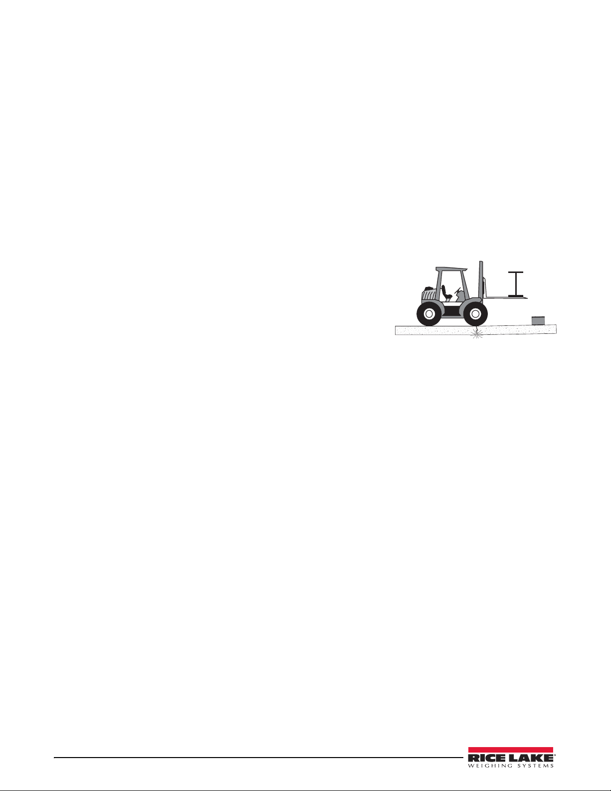
1.2.1 Foundation Slab Cure Period
Standard concrete reaches full strength after a 28-day cure. Note that
the concrete foundation slab must cure in a moist state for at least
seven days (three days for high-early concrete) before driving on it. At
seven days, standard concrete is at approximately 75% of its
maximum strength and can be driven on. Driving a loaded forklift on
the slab before it reaches 75% of maximum strength may damage the
foundation.
1.2.2 Delivery, Crane Rental, and Assembly Estimates
When scheduling scale delivery and crane/forklift rental for the unloading and frame placement, arrange a full day
and a crew of at least two assemblers. A two-man crew with crane or forklift can normally unload the scale and set,
align, and bolt all components in place on the first day.*
The next day, a crew of three or four can normally prepare the scale deck for concrete, pour and finish it before
evening.*
The third day, a crew of two can grout load cell base plates, run all conduit, make electrical connections, and
connect electronic equipment.*
When the concrete deck has cured, the scale can be corner-trimmed and calibrated with test weights and
placed into service.
* These estimated times may vary.
1.2.3 Recommended Equipment and Tools
2 Survivor
®
SR Siderail Truck Scale Assembly Instrucitons
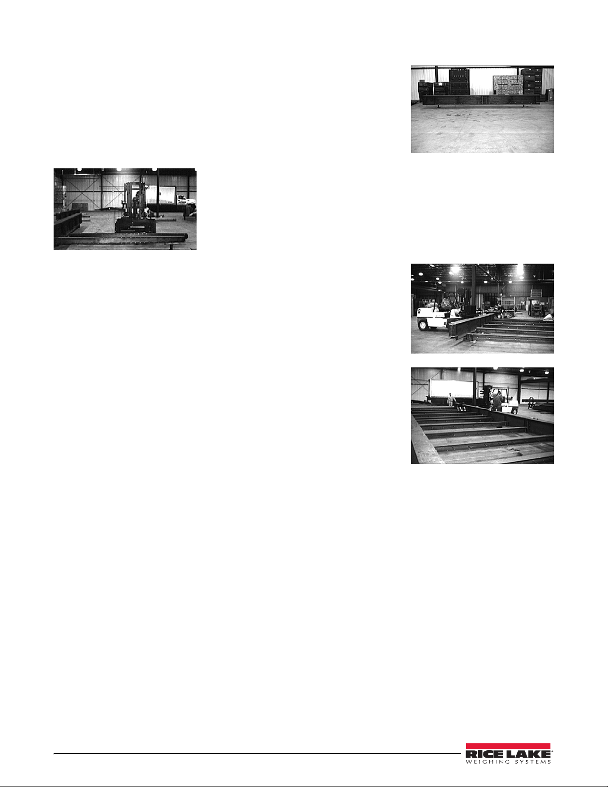
1.2.4 Determine Frame Assembly Sequence
The scale assembly sequence can be done in either of two ways: side-to-side or
end-to-end. Analyze your site access, equipment, and manpower to determine
which is better for you. The truck has been loaded in a way that avoids
double-handling beams on site. Main side rail beams and components can be
unloaded and set directly in place on the scale foundation in the order they will
be used. See the truck loading diagram on the first page of this manual.
If using a crane, park the crane beside and parallel to the scale foundation, with
the loaded truck parked on the other side of the crane.
If using a forklift to unload and set beams, you’ll need access to both sides of the truck to unload beams in order to
avoid double handling.
The first assembly step —unloading and setting the first row of side rail beams on one side of the scale—is the
same in both side-to-side or end-to-end assembly sequences.
Assemble Reference Beams on One Side
Main siderails on one side are placed on 8" setting blocks in their final
position on the far (least accessible) side of the scale. The end side rail
is set 1.5" from the concrete approach. If the next side rail is to be
bolted to the end one, set it directly adjacent and bolt it. If any side rail
is to be the start of a separate section, leave a 1" end gap to separate
independent platforms. The final end section is set 1.5" from the other
concrete approach. These beams are aligned straight with a string line
and squared with the foundation approaches. This line of side rail
beams becomes the reference line to which the other side rail and all
cross beams are aligned.
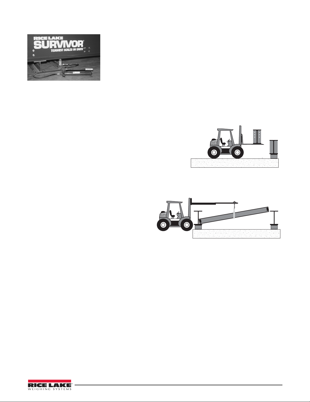
Side-to-Side Assembly Sequence
With this method, the side rail beams on the second side
are next set into position parallel but about 2" wider
than they will be in the final scale. This extra width
allows clearance for the cross beams to be lowered into
position with a sling on either a crane or
extension-boom forklift as shown at right.
Lower all cross beams into place on the side rail beam flanges and bolt them only to the first line of side rail beams
you set—the reference line side. When all cross beams are bolted to the reference side rail, chec k the straightness
of the side rail again with a string line to be certain it hasn’t moved. If it hasn’t, you can start bringing in the
siderails on the second side. Any siderails on the second side that will be end-bolted into a mu lti-module section
should not be bolted together at the ends yet—they will be too heavy and awkward to move in the required 2" if
combined now.
Begin bolting the cross beams to the siderails on the second side starting at one approach end. Use chain winches
(“comealongs”) to bring in the second side rail beam the extra 2" as you tighten the cross beam bolts. Keep
repositioning the chain winches on the siderails as you bolt down the line of cross beams from the approach end
through all scale sections.
A forklift can be used to slide each side rail section into place rather than step-by-step with chain winches. Your
forklift operator must have a delicate touch though or your reference side rail can be pushed out of alignment.
Introduction 3
End-to-End Assembly Sequence
This method requires more setting blocks, but no chain winches. More driving
on the slab is necessary, but the assembly can be done by a forklift with standard
length tines.
Begin by setting one row of side rail beams on 8" setting blocks as in the
previous method. If access is limited to one side, drive across the pad and
position these on the limited-access side. Align these reference siderails with a
string line and square with the approaches. Bolt adjoining siderails together
where needed to final torque settings.
Bring the cross beams onto the pad one at a time starting at one approach end.
Position each cross beam at its final location with one end resting on the side rail
flange. Bolt the cross beam to the side rail. Rest the other end of the cross beam
at a right angle to the side rail on a setting block 2" higher than your 8" blocks.
Repeat for all cross beams of the module.
When all cross beams for the first module are set and bolted to the reference side
rail, move the opposite side rail for the open side into position with the forklift.
With the cross beams resting on the side rail flange, raise the side rail and cross
beams enough to allow the cross beam setting blocks to be removed. Lower the
side rail onto two 8" setting blocks. Bolt the cross beams to this side rail so it
pulls into final position. Do not disturb the reference side rail positioning. Align
and square this completed section with the reference line and approaches.
Combined Modules: If a second module is to be bolted together into a
multi-module platform, move the second set of cross beams into position and
perform the same steps. When these cross beams are bolted to the reference side
rail, bring the opposite side rail into position. Lift the side rail and cross beams,
remove the 2" setting blocks, and align the side rail with the adjoining side rail
so the six holes in the adjoining end plates align. Bolt the siderails together.
Check alignment and square with the reference line and approaches.
Independent Modules: If the next module is not to be bolted to the first, set the
side rail 1" from the adjoining side rail. The final side rail will end 1.5" from the
approach.
4 Survivor
®
SR Siderail Truck Scale Assembly Instrucitons
2.0 Assemble Frame Siderails and Cross Beams
Whichever assembly sequence you chose, observe the following details.
• Use 8" high setting blocks so the deck frame will nearly match the level of the approaches.
• Don’t torque down cross beam assembly bolts tightly until the module is aligned and squared.
• Use a taut string line to align side rails.
• Measure diagonals with a 100' tape to assure frame is square within 1/4".
• Refer to the blueprints furnished with the scale for all component numbering sequences.
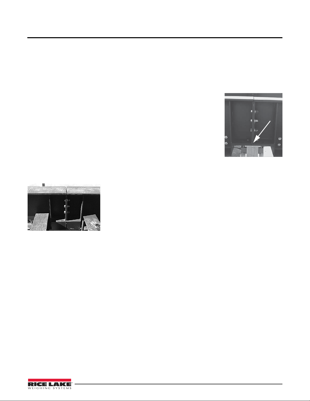
2.1 Connecting Siderails into Multi-Module Sections
A load cell mount sits directly under each multi-module joint splice and bears on both
siderail beams. The mount requires a flat surface at the joint to bolt to. Because of
material variances from the mill, the two beams may not be exactly the same height.
Always align the bottom of the beams when bolting together to create a flat surface for
the mounts top plate. Let any extra height protrude at the top of the siderail joint.
The six bolts connecting the two side rails must be torqued to 640 ft/lb. This cannot be
done with an impact wrench—a large torque wrench with extension handle will be
required.
2.2 Siderail Beam Identification and Positioning
The following sections outline the positioning and numbering of the SR truck scale siderail beams.
2.2.1 Siderail Positioning
Set all side rails with the cut-outs for the load cell mount down and the uncut
flange up. The headed anchor rods (Nelson studs) that will be encased in the
concrete deck face inward.
Gusset plates at the ends of single side rails which form an independent section
are solid.
Gusset plates at the end of side rails which bolt together to form a longer section
have three holes in each plate for these bolts as shown at left.
2.2.2 Siderail Numbering
All side rails are clearly marked with large numerals keyed to the final assembly drawing. Preview the drawing
before beginning to unload the truck. You will note that some side rails are interchangeable, while others are not
and must be placed exactly as the assembly drawing shows.
The truck will be loaded such that you can unload the side rails in order and set them directly into position on the
foundation without double handling. See the truck loading diagram for your scale model included with this manual.
2.3 Cross Beam Identification and Positioning
The following sections outline the positioning and numbering of the SR truck scale cross beams.
2.3.1 Cross Beam Positioning
Set all cross beams with the flush end of the drain tube up. The 3/8" threaded studs that attach the sheet metal
support bars should be near the bottom of the cross beam web.
Assemble Frame Siderails and Cross Beams 5
 Loading...