

Page 1
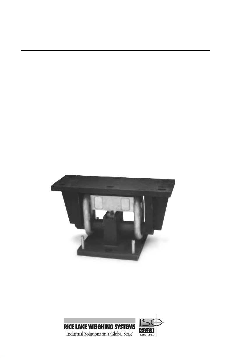
Translink
W eigh Module
Installation
Guide
™
25708
1
Page 2

Contents
1. Introduction ............................................................................. 1
2. Mechanical Installation............................................................ 2
2.1 General Installation Guidelines for Translink ................................2
2.2 Maintaining Scale Height and Center ........................................... 3
2.3 Mount and Load Cell Installation Procedures ...............................3
2.3.1 Assembling and Installing the Components ............................3
2.3.2 Leveling the Mount and Securing the Girder Chair .................4
2.3.3 Re-leveling, Securing, and Grouting the Base........................4
3. Load Cell Wiring...................................................................... 5
4. Adjustments and Calibration ................................................... 6
5. Troubleshooting....................................................................... 6
6. Maintenance and Replacement Parts ..................................... 7
6.1 Replacing a Load Cell...................................................................7
6.2 Replacement Parts ....................................................................... 7
8. Appendix ................................................................................. 8
9. Translink Limited Warranty...................................................... 9
Copyright © 1999 Rice Lake Weighing Systems. All rights reserved.
Printed in the United States of America.
Specifications subject to change without notice.
2/99
Page 3
1. Introduction
In this Translink™ manual, you will find a step-by-step approach to installing the
load cell mount in an easy, logical manner. You'll find complete information from
assembling and installing the components to testing the scale for weighing accuracy. Troubleshooting and replacement parts sections are also included in this
manual.
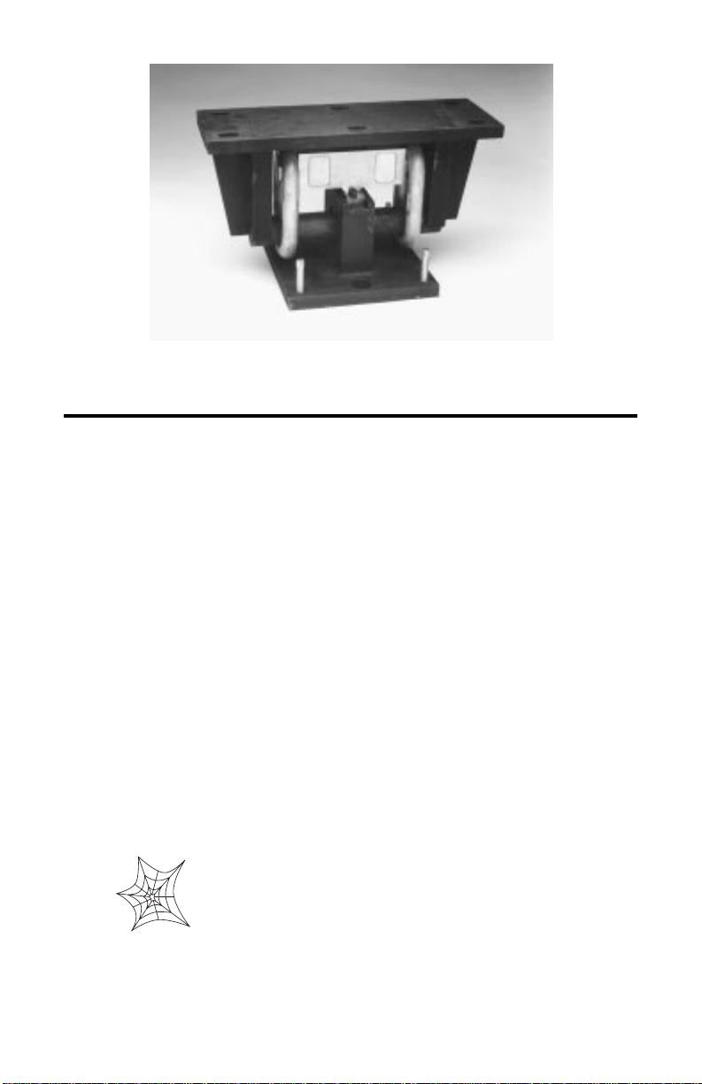
The Translink load cell mount is used for heavy capacity tank and truck weighing
applications. The mount is made of fabricated and hardened tool steel in capacities
of 25,000 lb to 100,000 lb. The pendulous action of the links allows self-centering
of the weighing platform, and the platform has free movement in all directions in
the horizontal plane. Install platform bumpers to prevent overtravel.
The mount is compatible with four different tool steel, double-ended shear beam
load cells. The RL75040A and the Sensortronics 65040A load cells are environmentally protected styles, whereas the RL75223, RTI 5223, and Sensortronics
65040S load cells are hermetically sealed styles.
The installation should be planned by a qualified structural engineer. Each installation is unique, and this manual is meant to serve only as a general guideline for
installation.
Authorized distributors and their employees can view or
download this manual from the Rice Lake Weighing
Systems distributor site at www.rlws.com.
3
Page 4
2. Mechanical Installation
a
a
a
a
a
a
a
aa
a
aa
aaa
a
a
a
a
a
a
a
aa
a
a
aa
a
a
a
a
a
aa
aa
a
a
a
a
a
a
a
a
a
a
a
a
a
a
a
a
a
a
a
a
a
aa
a
a
a
a
a
a
a
a
a
a
a
a
a
a
a
a
a
a
a
a
a
a
a
a
a
a
a
a
a
a
a
a
a
a
a
a
a
a
aa
a
a
aa
a
a
a
a
a
a
a
a
a
a
a
a
a
a
a
a
a
a
a
a
a
aa
aaa
a
a
a
a
aaa
a
a
a
a
a
a
a
a
a
a
a
a
a
a
a
a
a
a
a
aaa
a
2.1 General Installation Guidelines for Translink
1. Unless a good ground is already provided, install a system ground in the pit in
close proximity to the junction box. Use at least 1/2" x 8' copper-clad ground
rod. The indicator, junction box, weighbridge, and lightening protection
devices will be hooked to the system ground. Hook all other devices, such as
the printer, to the same AC power supply and ground as the indicator.
2. If the pit fills with water, proper drainage must be provided so that the load cell
mounts are not standing in water. Also, drainage loops should be provided on
any conduit or cables going to the junction box or load cells.
3. Install bumper bolts between the scale platform and the walls of the pit. Leave
about 1/8" clearance or as applicable for
temperature changes.
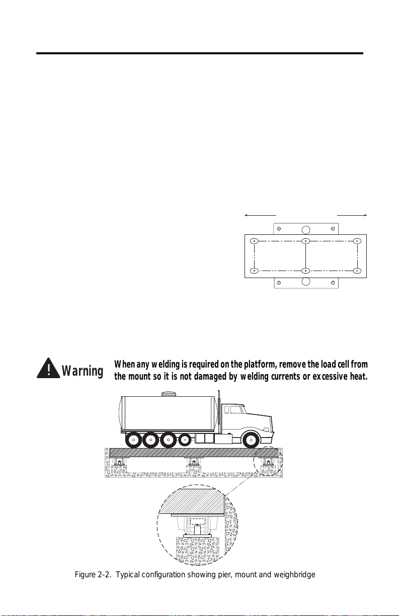
4. The mount must be positioned in the
direction of travel (Fig. 2-1).
5. The mounting surface for the base plate
and girder chair must be level and parallel
so that side loads and bending moments
are minimized. The mount assemblies
must be plumb and level within ±0.5°.
6. Because the load cell could be damaged during installation, do not use
excessive force or slam parts on the load cell.
Figure 2-1. Direction of travel (top view)
Direction of Travel
!
Warning
Figure 2-2. Typical configuration showing pier, mount and weighbridge
When any welding is required on the platform, remove the load cell from
the mount so it is not damaged by welding currents or excessive heat.
4
Page 5

2.2 Maintaining Scale Height and Center
Whether you are replacing an existing scale or installing all new load cell mounts,
you will need to maintain the required final height of your scale system.
• Build up the piers to ensure a minimum of 1/2" gap between each pier and base
plate for the final grout. See Appendix on page 8, for load cell mount height.
• Install cribbing to hold up the girder and platform to the required height for
normal truck scale operation. Make sure the cribbing is safe, before removing
any existing levers or mounts. Place wedges between the platform and the pit's
edges to center the platform in the pit.
• Remove the existing levers or mounts and install the new mounts one at a time
to continue to maintain the proper height. Remove all old scale parts from the
pit as soon as possible to prevent stumbling over them. Installation procedures
follow this section.
2.3 Mount and Load Cell Installation Procedures
2.3.1 Assembling and Installing the Components
Wherever the components come in contact with each other, such as the links with
the pin, pack well with grease.
When placing parts on the load cell, do not drop or slam parts on the load cell. This
sudden force could damage your load cell.
Caution
Do not weld on the girder or platform after the load cell
mounts have been installed.
1. If there is sufficient clearance between the pier and the underside of the
platform, place the base place on the pier in approximately its final position.
Otherwise, assemble the mount on the edge of the pier (away from the main
girder) and then slide it into the final position after assembly.
2. Screw the leveling bolts into the base plate until flush with the bottom of the
base. Place the bearing pad on the stand of
the base plate. Insert the two tension pins
Girder Chair
into the top of the stand. Position the load
cell on the bearing pad.
Load Cell
Bearing Pad
Base Plate
with
Leveling Bolts
Figure 2-3. Base Plate, Bearing Pad,
and Load Cell Assembly
Load cell models RL75040A and Sensortronics 65040A are shown. Load cell models
RL75223 and RTI5223 are slightly different.
Tension Pin
Figure 2-4. Links, Pin, Tension Pin, and
5
NOTE: Size
Markers Must
Face Outward
Two Links
Girder Chair Assembly
Pin
Page 6

3. Attach the two links to each end of the load cell so the raised lettering (size) on
each link is facing away from the load cell to avoid any interference. Slide the
pin in through the hole of the stand. Position the links on each end of the pin.
Place the girder chair on the ends of the pin (Fig. 2-4 on page 3).
4. Slide the load cell mount into place on the pier under the main girder. Align the
load cell mount in the direction of travel. (Fig. 2-1on page 2).
2.3.2 Leveling the Mount and Securing the Girder Chair
Leveling is the single most important part of the installation for acheiving highaccuracy weighing.
1. Adjust the leveling bolts equally to bring the top of the girder chair flush with
the bottom of the girder. Check to see whether the load cell mount is centered
under the girder, and adjust the mount if neccessary.
2. Mark the girder chair hold locations on the girder. See Appendix on page 8, for
girder chair mounting hole dimensions. Remove the load cell mount.
3. Use a cutting torch to make the holds in the girder. Be careful not to weaken the
structure unduly by making the holes too large.
4. Replace the mount, and bolt the girder chair to the girder (finger tight). Girder
chair bolts are not supplied. Recommended girder chair bolt size: 3/4", grade
5 or better.
5. Place shims, if necessary, between the top of the girder chair and the bottom of
the girder to level the girder chair within 0.5 degree of horizontal. Using a highquality bubble level (preferably a machinist's level), level the girder chair in
both directions (front to back and left to right). The shims should be as large as
possible to distribute the load. If necessary, adjust the leveling bolts to insert
the shims.
6. Level the base plate within 0.5 degree of horizontal to achieve a scale accuracy
of 0.1% or better. Level the base plate in both directions (front to back and right
to left). The base plate should be parallel with the girder chair, and the links
should be plumb.
2.3.3 Re-leveling, Securing, and Grouting the Base
1. Remove the cribbing for the particular mount and lower the platform gently so
it is resting soley on the mount. Again, adjust the leveling bolts if the deck is
not quite level with the top of the pit.
2. Re-level the mount and ensure that the links are hanging plumb. A perfectly
level system will minimize side load and bending moments.
3. Install all the other mounts in the system in the above manner before bolting and
grouting the base plates. After all the mounts are in place, remove all other
cribbing, and remove the platform wedges making sure it is still centered in the
pit. If not, then re-wedge and adjust the mounts as necessary. When you are sure
that the platform is at the final height and has the proper clearance, anchor the
base plates.
6
Page 7

4. Drill holes in the concrete pier maintaining the height of the leveling bolts. See
a
a
a
a
a
a
a
aa
a
aa
aaa
a
a
a
a
a
a
a
aa
a
a
aa
a
a
a
a
a
aa
aa
a
a
a
a
aa
a
a
a
a
a
a
a
a
a
a
a
a
a
a
a
aa
a
a
a
a
a
a
a
a
a
a
a
a
a
a
a
Appendix on page 8, for base plate mounting hole locations. Use concrete stud
anchors or equivalent to secure the base plate. Use no less than a 7/8"x 7" anchor
bolt. Drive each anchor bolt, with the nut and washer on, to firmly set the anchor
in place. Tighten the nuts (finger tight).
5. Make a final check to see that the girder chairs and base plates are level, the
platform is at the final height, and proper clearance has been maintained.
6. After building a structure around the base plates to contain the grout, pour the
liquid ground under the base plates. Use good-quality, non-shrinking grout.
Push under the base plate to remove any air pockets.
7. After the grout has hardend (time specified by grout supplier), tighten all girder
chair bolts and base plate anchors. Back the four leveling bolts out of the grout.
Attach a grounding strap from the girder chair to the base plate. While you are
waiting for the grout to harden, you can start hooking up the electrical
connections (see Section 3, below).
3. Load Cell Wiring
1. Route the load cell cables so they will not be damaged or cut. Cable should not
be routed near heat sources greater than
150°F. Do not shorten any load cell cable.
The load cell is temperature complensated
with the supplied length of cable. Cutting
the cable will affect temperature compensation. Coil and protect excess cable so it
will not be mechanically damaged or be
sitting in water. It is highly recommended
protecting the cables in steel conduit.
2. Provide a drip loop in all cables so that water or other liquids will not run
directly down the cables onto either the load cells or the junction box. Attach
load cell cable to the dead structure, not the vessel.
3. For better performance, use positive and negative remote sense lines if the
wiring running from the junction box to the indicator is longer than 25 feet.
4. Connect cables for load cells to the summing board in the junction box
according to the guide shown below and the labels on the terminal strips of the
junction box. To verify the wiring scheme, see the certification shipped with
each load cell.
Figure 3-1. Drip loop cabling
Junction
Box
sroloCeriWlleCdaoLsroloCeriWlleCdaoL
sroloCeriWlleCdaoLsroloCeriWlleCdaoL
sroloCeriWlleCdaoL
roloCeriW
deRCXE+CXE+
kcalBCXE–CXE–
neerGGIS+GIS–
etihWGIS–GIS+
eraBroyarGDLEIHSDLEIHS
7
noitcnuF
gnidaeRevitageN gnidaeRevitisoP
Page 8

4. Adjustments and Calibration
Note: Proceed with the adjustments and calibration only after the grout under the
base plates is completely hardened and all mounts are firmly bolted in place.
1. Your local Weights and Measures regulations will dictate the type of test required, such as section test, corner test,
build up, etc.
2. Adjust the junction box potentiometers
so that a weight placed anywhere on the
platform gives the same reading at each
load cell. For more detailed instructions
refer to the instructions sent with the
junction box.
Figure 4-1. Summing board and potentiometers
3. Watch for any unusual readings, which might indicate problems in the
installation. Remember, on any adjustment that you make, you should be able
to predict the outcome.
4. After you install the bumper bolts, re-test the scale to see that it is weighing
properly. If the scale changes calibration, you know the problem is from the
bumper bolts, and not from the load cell mounting installation.
Refer to the digital indicator installation manual for specific calibration procedures
to use with the particular indicator.
+EX
–EX
SHD
SHD
–EX
+EX
+SI
–SI
–SI
+SI
CELL 1
CELL 4
Potentiometers
100 K
JU1
INDICATOR
SHD
–SI
+SI
–SE
–EX
JU4
+SE
+EX
100 K
23126
Rev. A
100 K
100 K
+EX
CELL 2
–EX
JU2
+SI
–SI
SHD
SHD
–SI
+SI
JU3
–EX
+EX
CELL 3
5. Troubleshooting
1. If the system powers up and gives some sort of stable digital readout that varies
with the load on the system, any system problems are probably caused by
factors other than the load cells. The load cells are often blamed for a
malfunctioning system, but 90% of the time, the problem lies elsewhere. Look
for mechanical causes for your problem first.
2. If the system can be calibrated but doesn't return to zero, loses calibration, or
demonstrates non-linearity or non-repeatability, see the following chart for
possible causes and do the following checks.
motpmySmotpmyS
motpmySmotpmyS esuaCelbissoPesuaCelbissoP
motpmyS
orezotnruteroN
ytiraenil-noN daoledisrognidnibgnisuacdaolrednunoitcelfedronoisnapxelamrehT
ytilibataeper-noN
noitarbilactsoL gnidniblacinahcem;melborperutsiom;bmulprolevelfotuO
tuodaergnitfirD gnidniblacinahcem;llecdaolro,selbac,xobnoitcnujnierutsioM
noitarbilac
esuaCelbissoPesuaCelbissoP
esuaCelbissoP
metsystsolevahyam;sllecdaolrednuroslaesnisirbedrognidniblacinahceM
gnidniblacinahcem;egamad
kcohsrodaolrevollecdaol,erutsiomybdesuacgnitfird;tnuomllecdaolesooL
8
Page 9

6. Maintenance and Replacement Parts
6.1 Replacing a Load Cell
1. Jack up the girder chair and weighbridge away from the pin in the load cell
assembly. Jack it high enough only to remove the pin.
2. Remove the pin from the links and pull it through the hold on the stand. Remove
the links from the load cell, and remove the load cell.
3. Position the new load cell on the bearing pad. Attach the two links to each end
of the load cell. Slide the pin in through the hold of the stand. Position the links
on each end of the pin.
4. Lower the girder chair and weighbridge Gently onto the pin so the load cell is
not damaged by excessive shock.
5. Check if the load cell mounts are level (see Section 2.33 Re-leveling, Securing,
and Grouting the Base, on page 4).
6. Test the scale, and recalibrate if necessary.
6.2 Replacement Parts
Tension Pin
Pin
Base Plate
Leveling Bolt
Girder Chair
Load Cell
Link
Bearing Pad
Description Qty A* B* C*
TranslinkTM Mount (excluding load cell).....................17970.........17971.........17972
Tension Pin..................................................2..........15302........15300.........15300
Base Plate...................................................1 ........ 18458.........18455 ........18458
Leveling Screw.............................................4.........H702-1........H702-1......H702-1
Pin...............................................................1.........18470.........18468.........18469
Bearing Pad.................................................1.........18452.........18453.........18453
Link, Weldless End.......................................2.........17809.........17810.........17809
Girder Chair.................................................1..........18465.........18467 ........18466
Double-Ended Shear Beam Load Cell .........1..........(see Load Cell Product Selection
Guide for load cell part numbers).
*A – mount compatible with load cells RL75223/5223 in capacities of 50,000,
65,000 and 100,000 lb each.
*B – mount compatible with load cells RL75040A/65040A in capacities of
25,000 and 40,000 lb each.
*C – mount capatible with load cells RL75040A/65040A in capacities of 50,000,
60,000 and 75,000 lb each.
9
Page 10

8. Appendix
W2
W
L
W3
L3
L3
W1
H1
H
H2
L2
L1
C
W4
L5
L4
detaR
C H 1H 2H L 1L 2L 3L 4L 5L W 1W 2W 3W 4W 5W
.paC
A*05.139.2100.100.105.2205.157.105.957.1188.557.719.52.552.152.957.11
B*05.188.900.100.105.8105.157.105.757.1188.557.719.52.552.152.957.11
C*05.128.2100.100.105.2205.157.105.957.1188.557.719.52.552.152.957.11
W5
SEHCNI-SNOISNEMID
*A – mount for load cells RL75223/5223 in capacities of 50,000 to 100,000 lb.
*B – mount for load cells RL75040A/65040A in capacities of 25,000 to 40,000 lb.
*C – mount for load cells RL75040A/65040A in capacities of 50,000 to 75,000 lb.
10
Page 11

9. Translink Limited Warranty
Rice Lake Weighing Systems (RLWS) warrants that all RLWS brand load cells properly
installed by a Distributor or Original Equipment Manufacturer (OEM) will operate per
written specifications. All load cell products are warranted against defects in materials and
workmanship for two (2) years. Products marked as “waterproof” are warranted against
defects in materials and workmanship relating to moisture ingress.
RLWS warrants that the equipment sold hereunder will conform to the current written
specifications authorized by RLWS. RLWS warrants the equipment against faulty workmanship and defective materials. If any equipment fails to conform to these warranties, RLWS
will, at its option, repair or replace such goods returned within the warranty period subject to
the following conditions:
• Upon discovery by Buyer of such non-conformity, RLWS will be given prompt written
notice with a detailed explanation of the alleged deficiencies.
• Examination of such equipment by RLWS confirms that the non-conformity actually
exists, and was not caused by accident, misuse, neglect, alteration, improper installation,
improper repair or improper testing; RLWS shall be the sole judge of all alleged nonconformities.
• Such equipment has not been modified, altered, or changed by any person other than
RLWS or its duly authorized repair agents.
• RLWS will have a reasonable time to repair or replace the defective equipment. Buyer
is responsible for shipping charges both ways.
• In no event will RLWS be responsible for travel time or on-location repairs, including
assembly or disassembly of equipment, nor will RLWS be liable for the cost of any
repairs made by others.
THESE WARRANTIES EXCLUDE ALL OTHER WARRANTIES, EXPRESSED OR
IMPLIED, INCLUDING WITHOUT LIMITATION WARRANTIES OF MERCHANTABILITY OR FITNESS FOR A PARTICULAR PURPOSE. NEITHER RLWS NOR
DISTRIBUTOR WILL, IN ANY EVENT, BE LIABLE FOR INCIDENTAL OR CONSEQUENTIAL DAMAGES.
RLWS AND BUYER AGREE THAT RLWS’S SOLE AND EXCLUSIVE LIABILITY
HEREUNDER IS LIMITED TO REPAIR OR REPLACEMENT OF SUCH GOODS. IN
ACCEPTING THIS WARRANTY, THE BUYER WAIVES ANY AND ALL OTHER
CLAIMS TO WARRANTY.
SHOULD THE SELLER BE OTHER THAN RLWS, THE BUYER AGREES TO LOOK
ONLY TO THE SELLER FOR WARRANTY CLAIMS.
No terms, conditions, understanding, or agreements purporting to modify the terms of this
warranty shall have any legal effect unless made in writing and signed by a corporate officer
of RLWS and the Buyer.
© 1999 Rice Lake Weighing Systems, Inc. Rice Lake, WI USA. All Rights Reserved.
RICE LAKE WEIGHING SYSTEMS • 230 WEST COLEMAN STREET
RICE LAKE, WISCONSIN 54868 • USA
11
 Loading...