


MSI TranSend 7000 Series
Single and Multiple Channel Transmitters and Receivers
Technical Manual
PN 167375 Rev EApril 19, 2023

© Rice Lake Weighing Systems. All rights reserved.
Rice Lake Weighing Systems
®
is a registered trademark of
Rice Lake Weighing Systems.
All other brand or product names within this publication are trademarks or
registered trademarks of their respective companies.
All information contained within this publication is, to the best of our knowledge, complete and
accurate at the time of publication. Rice Lake Weighing Systems reserves the right to make
changes to the technology, features, specifications and design of the equipment without notice.
The most current version of this publication, software, firmware and all other product
updates can be found on our website:
www.ricelake.com

Revision History
This section tracks and describes manual revisions for awareness of major updates.
Revision Date Description
E April 19, 2023 Established revision history; added RF regulatory information
Table i. Revision Letter History
Revision History
Technical training seminars are available through Rice Lake Weighing Systems.
Course descriptions and dates can be viewed at www.ricelake.com/training
or obtained by calling 715-234-9171 and asking for the training department.
© Rice Lake Weighing Systems ● All Rights Reserved 3

MSI TranSend 7000 Series
Contents
1.0 Introduction . . . . . . . . . . . . . . . . . . . . . . . . . . . . . . . . . . . . . . . . . . . . . . . . . . . . . . . . . . . . . . . . . . . . . . . . . . . . 7
1.1 Overview . . . . . . . . . . . . . . . . . . . . . . . . . . . . . . . . . . . . . . . . . . . . . . . . . . . . . . . . . . . . . . . . . . . . . . . . . . . . . . . . . . . . . . . . . . . 7
1.1.1 Transmitters . . . . . . . . . . . . . . . . . . . . . . . . . . . . . . . . . . . . . . . . . . . . . . . . . . . . . . . . . . . . . . . . . . . . . . . . . . . . . . . . . 7
1.1.2 Receivers . . . . . . . . . . . . . . . . . . . . . . . . . . . . . . . . . . . . . . . . . . . . . . . . . . . . . . . . . . . . . . . . . . . . . . . . . . . . . . . . . . . 7
1.2 Standard Features . . . . . . . . . . . . . . . . . . . . . . . . . . . . . . . . . . . . . . . . . . . . . . . . . . . . . . . . . . . . . . . . . . . . . . . . . . . . . . . . . . . 8
1.3 FCC Compliance. . . . . . . . . . . . . . . . . . . . . . . . . . . . . . . . . . . . . . . . . . . . . . . . . . . . . . . . . . . . . . . . . . . . . . . . . . . . . . . . . . . . . 8
1.4 Safety . . . . . . . . . . . . . . . . . . . . . . . . . . . . . . . . . . . . . . . . . . . . . . . . . . . . . . . . . . . . . . . . . . . . . . . . . . . . . . . . . . . . . . . . . . . . . 9
1.5 MSI-7000 Front Panel . . . . . . . . . . . . . . . . . . . . . . . . . . . . . . . . . . . . . . . . . . . . . . . . . . . . . . . . . . . . . . . . . . . . . . . . . . . . . . . . 10
1.6 MSI-7001 Front Panel . . . . . . . . . . . . . . . . . . . . . . . . . . . . . . . . . . . . . . . . . . . . . . . . . . . . . . . . . . . . . . . . . . . . . . . . . . . . . . . . 11
1.7 MSI-7000HD Front Panel . . . . . . . . . . . . . . . . . . . . . . . . . . . . . . . . . . . . . . . . . . . . . . . . . . . . . . . . . . . . . . . . . . . . . . . . . . . . . 12
1.8 MSI-7001HD Front Panel . . . . . . . . . . . . . . . . . . . . . . . . . . . . . . . . . . . . . . . . . . . . . . . . . . . . . . . . . . . . . . . . . . . . . . . . . . . . . 13
2.0 Installation . . . . . . . . . . . . . . . . . . . . . . . . . . . . . . . . . . . . . . . . . . . . . . . . . . . . . . . . . . . . . . . . . . . . . . . . . . . . 14
2.1 Unpacking and Assembly . . . . . . . . . . . . . . . . . . . . . . . . . . . . . . . . . . . . . . . . . . . . . . . . . . . . . . . . . . . . . . . . . . . . . . . . . . . . . 14
2.2 Connect Load Cell Cables . . . . . . . . . . . . . . . . . . . . . . . . . . . . . . . . . . . . . . . . . . . . . . . . . . . . . . . . . . . . . . . . . . . . . . . . . . . . 14
2.2.1 MSI-7001 TranSend. . . . . . . . . . . . . . . . . . . . . . . . . . . . . . . . . . . . . . . . . . . . . . . . . . . . . . . . . . . . . . . . . . . . . . . . . . 14
2.2.2 MSI-7000 TranSend and MSI-7000HD . . . . . . . . . . . . . . . . . . . . . . . . . . . . . . . . . . . . . . . . . . . . . . . . . . . . . . . . . . . 15
2.2.3 MSI-7001HD . . . . . . . . . . . . . . . . . . . . . . . . . . . . . . . . . . . . . . . . . . . . . . . . . . . . . . . . . . . . . . . . . . . . . . . . . . . . . . . 15
2.3 Connect Power . . . . . . . . . . . . . . . . . . . . . . . . . . . . . . . . . . . . . . . . . . . . . . . . . . . . . . . . . . . . . . . . . . . . . . . . . . . . . . . . . . . . . 16
2.3.1 MSI-7001 TranSend. . . . . . . . . . . . . . . . . . . . . . . . . . . . . . . . . . . . . . . . . . . . . . . . . . . . . . . . . . . . . . . . . . . . . . . . . . 16
2.4 Network Connections . . . . . . . . . . . . . . . . . . . . . . . . . . . . . . . . . . . . . . . . . . . . . . . . . . . . . . . . . . . . . . . . . . . . . . . . . . . . . . . . 16
2.5 Analog Output Connection . . . . . . . . . . . . . . . . . . . . . . . . . . . . . . . . . . . . . . . . . . . . . . . . . . . . . . . . . . . . . . . . . . . . . . . . . . . . 16
2.5.1 MSI-7001 TranSend Connector . . . . . . . . . . . . . . . . . . . . . . . . . . . . . . . . . . . . . . . . . . . . . . . . . . . . . . . . . . . . . . . . . 16
2.5.2 MSI-7000 TranSend Wiring . . . . . . . . . . . . . . . . . . . . . . . . . . . . . . . . . . . . . . . . . . . . . . . . . . . . . . . . . . . . . . . . . . . . 16
2.5.3 PLC Wiring Diagrams. . . . . . . . . . . . . . . . . . . . . . . . . . . . . . . . . . . . . . . . . . . . . . . . . . . . . . . . . . . . . . . . . . . . . . . . . 17
2.6 Relays . . . . . . . . . . . . . . . . . . . . . . . . . . . . . . . . . . . . . . . . . . . . . . . . . . . . . . . . . . . . . . . . . . . . . . . . . . . . . . . . . . . . . . . . . . . . 18
2.7 RF Network Transmission Strength . . . . . . . . . . . . . . . . . . . . . . . . . . . . . . . . . . . . . . . . . . . . . . . . . . . . . . . . . . . . . . . . . . . . . 18
2.8 Radio Compliance. . . . . . . . . . . . . . . . . . . . . . . . . . . . . . . . . . . . . . . . . . . . . . . . . . . . . . . . . . . . . . . . . . . . . . . . . . . . . . . . . . . 19
2.8.1 802.15.4 (XBee 3 and XBee 3-PRO) . . . . . . . . . . . . . . . . . . . . . . . . . . . . . . . . . . . . . . . . . . . . . . . . . . . . . . . . . . . . . 19
2.8.2 802.15.4 (XBee 2SC) . . . . . . . . . . . . . . . . . . . . . . . . . . . . . . . . . . . . . . . . . . . . . . . . . . . . . . . . . . . . . . . . . . . . . . . . . 19
2.8.3 Wi-Fi. . . . . . . . . . . . . . . . . . . . . . . . . . . . . . . . . . . . . . . . . . . . . . . . . . . . . . . . . . . . . . . . . . . . . . . . . . . . . . . . . . . . . . 19
2.8.4 FHSS (Frequency Hopper Spread Spectrum) . . . . . . . . . . . . . . . . . . . . . . . . . . . . . . . . . . . . . . . . . . . . . . . . . . . . . . 20
2.9 Antenna Options . . . . . . . . . . . . . . . . . . . . . . . . . . . . . . . . . . . . . . . . . . . . . . . . . . . . . . . . . . . . . . . . . . . . . . . . . . . . . . . . . . . . 20
2.9.1 Available Antennas . . . . . . . . . . . . . . . . . . . . . . . . . . . . . . . . . . . . . . . . . . . . . . . . . . . . . . . . . . . . . . . . . . . . . . . . . . 21
2.10 Mounting the Enclosure . . . . . . . . . . . . . . . . . . . . . . . . . . . . . . . . . . . . . . . . . . . . . . . . . . . . . . . . . . . . . . . . . . . . . . . . . . . . . . 22
3.0 ScaleCore Connect . . . . . . . . . . . . . . . . . . . . . . . . . . . . . . . . . . . . . . . . . . . . . . . . . . . . . . . . . . . . . . . . . . . . . 26
3.1 Installation . . . . . . . . . . . . . . . . . . . . . . . . . . . . . . . . . . . . . . . . . . . . . . . . . . . . . . . . . . . . . . . . . . . . . . . . . . . . . . . . . . . . . . . . . 26
3.1.1 System Requirements . . . . . . . . . . . . . . . . . . . . . . . . . . . . . . . . . . . . . . . . . . . . . . . . . . . . . . . . . . . . . . . . . . . . . . . . 26
3.1.2 Install Program . . . . . . . . . . . . . . . . . . . . . . . . . . . . . . . . . . . . . . . . . . . . . . . . . . . . . . . . . . . . . . . . . . . . . . . . . . . . . . 26
3.1.3 Connect Product to Computer . . . . . . . . . . . . . . . . . . . . . . . . . . . . . . . . . . . . . . . . . . . . . . . . . . . . . . . . . . . . . . . . . . 27
3.2 Configuration/Setup . . . . . . . . . . . . . . . . . . . . . . . . . . . . . . . . . . . . . . . . . . . . . . . . . . . . . . . . . . . . . . . . . . . . . . . . . . . . . . . . . 27
3.2.1 Connected Devices . . . . . . . . . . . . . . . . . . . . . . . . . . . . . . . . . . . . . . . . . . . . . . . . . . . . . . . . . . . . . . . . . . . . . . . . . . 27
3.2.2 Device Profiles . . . . . . . . . . . . . . . . . . . . . . . . . . . . . . . . . . . . . . . . . . . . . . . . . . . . . . . . . . . . . . . . . . . . . . . . . . . . . . 27
3.2.3 Configuration . . . . . . . . . . . . . . . . . . . . . . . . . . . . . . . . . . . . . . . . . . . . . . . . . . . . . . . . . . . . . . . . . . . . . . . . . . . . . . . 28
3.2.4 Load Cells . . . . . . . . . . . . . . . . . . . . . . . . . . . . . . . . . . . . . . . . . . . . . . . . . . . . . . . . . . . . . . . . . . . . . . . . . . . . . . . . . 32
3.2.5 Calibration . . . . . . . . . . . . . . . . . . . . . . . . . . . . . . . . . . . . . . . . . . . . . . . . . . . . . . . . . . . . . . . . . . . . . . . . . . . . . . . . . 35
3.2.6 Inputs / Outputs . . . . . . . . . . . . . . . . . . . . . . . . . . . . . . . . . . . . . . . . . . . . . . . . . . . . . . . . . . . . . . . . . . . . . . . . . . . . . 37
Rice Lake continually offers web-based video training on a growing selection
of product-related topics at no cost. Visit www.ricelake.com/webinars
4 Visit our website www.RiceLake.com

Contents
3.2.7 Monitors . . . . . . . . . . . . . . . . . . . . . . . . . . . . . . . . . . . . . . . . . . . . . . . . . . . . . . . . . . . . . . . . . . . . . . . . . . . . . . . . . . . 37
3.3 Advanced Setup . . . . . . . . . . . . . . . . . . . . . . . . . . . . . . . . . . . . . . . . . . . . . . . . . . . . . . . . . . . . . . . . . . . . . . . . . . . . . . . . . . . . 38
3.3.1 File Menu . . . . . . . . . . . . . . . . . . . . . . . . . . . . . . . . . . . . . . . . . . . . . . . . . . . . . . . . . . . . . . . . . . . . . . . . . . . . . . . . . . 38
3.3.2 Administration Menu . . . . . . . . . . . . . . . . . . . . . . . . . . . . . . . . . . . . . . . . . . . . . . . . . . . . . . . . . . . . . . . . . . . . . . . . . 39
3.3.3 Communications . . . . . . . . . . . . . . . . . . . . . . . . . . . . . . . . . . . . . . . . . . . . . . . . . . . . . . . . . . . . . . . . . . . . . . . . . . . . 39
3.3.4 Program . . . . . . . . . . . . . . . . . . . . . . . . . . . . . . . . . . . . . . . . . . . . . . . . . . . . . . . . . . . . . . . . . . . . . . . . . . . . . . . . . . . 41
3.3.5 Device Profiles . . . . . . . . . . . . . . . . . . . . . . . . . . . . . . . . . . . . . . . . . . . . . . . . . . . . . . . . . . . . . . . . . . . . . . . . . . . . . . 43
3.3.6 Maintenance. . . . . . . . . . . . . . . . . . . . . . . . . . . . . . . . . . . . . . . . . . . . . . . . . . . . . . . . . . . . . . . . . . . . . . . . . . . . . . . . 43
3.3.7 Stream Print String. . . . . . . . . . . . . . . . . . . . . . . . . . . . . . . . . . . . . . . . . . . . . . . . . . . . . . . . . . . . . . . . . . . . . . . . . . . 44
4.0 MSI mV Scale Calibration . . . . . . . . . . . . . . . . . . . . . . . . . . . . . . . . . . . . . . . . . . . . . . . . . . . . . . . . . . . . . . . . 46
5.0 Optional Rugged Remote . . . . . . . . . . . . . . . . . . . . . . . . . . . . . . . . . . . . . . . . . . . . . . . . . . . . . . . . . . . . . . . . 49
5.1 Operation . . . . . . . . . . . . . . . . . . . . . . . . . . . . . . . . . . . . . . . . . . . . . . . . . . . . . . . . . . . . . . . . . . . . . . . . . . . . . . . . . . . . . . . . . 49
5.1.1 Power . . . . . . . . . . . . . . . . . . . . . . . . . . . . . . . . . . . . . . . . . . . . . . . . . . . . . . . . . . . . . . . . . . . . . . . . . . . . . . . . . . . . . 50
5.1.2 Zero . . . . . . . . . . . . . . . . . . . . . . . . . . . . . . . . . . . . . . . . . . . . . . . . . . . . . . . . . . . . . . . . . . . . . . . . . . . . . . . . . . . . . . 50
5.1.3 Tare . . . . . . . . . . . . . . . . . . . . . . . . . . . . . . . . . . . . . . . . . . . . . . . . . . . . . . . . . . . . . . . . . . . . . . . . . . . . . . . . . . . . . . 50
5.1.4 Programmable Function Keys . . . . . . . . . . . . . . . . . . . . . . . . . . . . . . . . . . . . . . . . . . . . . . . . . . . . . . . . . . . . . . . . . . 50
5.2 Conflict and Jamming Considerations. . . . . . . . . . . . . . . . . . . . . . . . . . . . . . . . . . . . . . . . . . . . . . . . . . . . . . . . . . . . . . . . . . . . 50
5.3 FCC Compliance. . . . . . . . . . . . . . . . . . . . . . . . . . . . . . . . . . . . . . . . . . . . . . . . . . . . . . . . . . . . . . . . . . . . . . . . . . . . . . . . . . . . 50
6.0 Specifications . . . . . . . . . . . . . . . . . . . . . . . . . . . . . . . . . . . . . . . . . . . . . . . . . . . . . . . . . . . . . . . . . . . . . . . . . 51
Technical training seminars are available through Rice Lake Weighing Systems.
Course descriptions and dates can be viewed at www.ricelake.com/training
or obtained by calling 715-234-9171 and asking for the training department.
© Rice Lake Weighing Systems ● All Rights Reserved 5

MSI TranSend 7000 Series
Rice Lake continually offers web-based video training on a growing selection
of product-related topics at no cost. Visit www.ricelake.com/webinars
6 Visit our website www.RiceLake.com

Introduction
1.0 Introduction
The MSI TranSend 7000 Series of wireless load cell interface transmitters and receivers are efficient communication devices
that replace the need for traditional wire runs. The MSI TranSend 7000 Series is designed to work with ScaleCore-based
products and are compatible with a broad range of transmitting and receiving devices. The transmitters in the series can
interface with any type of load cell. This manual provides the details for installation, configuration and calibration for the
MSI-7000 TranSend, MSI-7001 TranSend, MSI-7000HD and MSI-7001HD.
Manuals and additional resources are available from Rice Lake Weighing Systems at
Warranty information is available at www.ricelake.com/warranties
www.ricelake.com/manuals
1.1 Overview
The MSI TranSend 7000 Series offers a wireless option in systems where it would be difficult to have a load cell cable. Replacing
the cable with an RF link, the output will be calibrated to match the device that the cable was connected to. A single MSI
TranSend 7000 Series transmitter or receiver can be used to communicate with a ScaleCore-based remote display or indicator.
A paired transmitter and receiver can be used to wirelessly send weigh data to virtually any indicator or remote display.
Transmitter
Figure 1-1. MSI TranSend 7000 Series
1.1.1 Transmitters
An MSI TranSend 7000 Series transmitter can be used to send weigh data wirelessly to an MSI TranSend 7000 Series receiver
or a ScaleCore-based remote display. ScaleCore-based indicators can also be used as transmitters to send weigh data to
either an MSI TranSend 7000 Series receiver or a ScaleCore-based remote display.
Transmitter Model Options
• MSI-7000 TranSend
• MSI-7001 TranSend
• MSI-7000HD
• MSI-7001HD
• MSI-3460
• MSI-4260
Transmitter and ReceiverReceiver
• MSI-7300
• MSI-8000HD
• MSI-8004HD
NOTE: Refer to Section 1.5 on page 10 for available MSI TranSend 7000 Series model configurations.
1.1.2 Receivers
An MSI TranSend 7000 Series receiver can be used to receive weigh data wirelessly from an MSI TranSend 7000 Series
transmitter or a ScaleCore-based indicator. ScaleCore-based remote displays can also be used as receivers to receive weigh
data from either an MSI TranSend 7000 Series transmitter or a ScaleCore-based indicator. All MSI receivers are compatible with
all MSI transmitters, except for the receivers that provide an mV signal to a digital weight indicator.
Receiver Model Options
• MSI-7000 TranSend
• MSI-7001 TranSend
NOTE: Refer to Section 1.5 on page 10 for available MSI TranSend 7000 Series model configurations.
• MSI-8000
• MSI-8000HD
© Rice Lake Weighing Systems ● All Rights Reserved 7
• MSI-8004HD
• LaserLight 2

MSI TranSend 7000 Series
1.2 Standard Features
• Works with any basic digital weight indicator
• Excitation to load cell(s) provided by the transmitter, not the indicator
• Each transmitter/receiver set is individually paired for communication
• Auto-sleep mode - power down during non-use, power up with weight change
• Serial communication cable included
Additional HD Features
• IP68 milled aluminum enclosure
• 2nd radio modem available (MSI-7000HD only)
1.3 FCC Compliance
United States
This equipment has been tested and found to comply with the limits for a Class A digital device, pursuant to Part 15 of the FCC
Rules. These limits are designed to provide reasonable protection against harmful interference when the equipment is operated
in a commercial environment. This equipment generates, uses and can radiate radio frequency energy and, if not installed and
used in accordance with the instruction manual, may cause harmful interference to radio communications. Operation of this
equipment in a residential area is likely to cause harmful interference in which case the user will be required to correct the
interference at his own expense.
Canada
This digital apparatus does not exceed the Class A limits for radio noise emissions from digital apparatus set out in the Radio
Interference Regulations of the Canadian Department of Communications.
Le présent appareil numérique n'émet pas de bruits radioélectriques dépassant les limites applicables aux appareils
numériques de la Class A prescites dans le Règlement sur le brouillage radioélectrique edicté par le ministère des
Communications du Canada.
8 Visit our website www.RiceLake.com

Introduction
1.4 Safety
Safety Definitions:
DANGER: Indicates an imminently hazardous situation that, if not avoided, will result in death or serious injury. Includes
hazards that are exposed when guards are removed.
WARNING: Indicates a potentially hazardous situation that, if not avoided, could result in serious injury or death. Includes
hazards that are exposed when guards are removed.
CAUTION: Indicates a potentially hazardous situation that, if not avoided, could result in minor or moderate injury.
IMPORTANT: Indicates information about procedures that, if not observed, could result in damage to equipment or
corruption to and loss of data.
General Safety
Do not operate or work on this equipment unless this manual has been read and all instructions are understood.
Failure to follow the instructions or heed the warnings could result in injury or death. Contact any Rice Lake
Weighing Systems dealer for replacement manuals.
WARNING
Failure to heed could result in serious injury or death.
Do not allow minors (children) or inexperienced persons to operate this unit.
Do not stand near a load being lifted as it is a potential falling hazard. Keep a safe distance.
Do not use for purposes other then weight taking or dynamic load monitoring.
Do not use any load bearing component that is worn beyond five percent of the original dimension.
Do not use any associated lifting product if any of the load bearing components are cracked, deformed or show signs of fatigue.
Do not exceed the rated load limit of the associated scale/dynamometer unit, rigging element or the lifting structure.
Do not allow multi-point contact with the hook, shackle or lifting eye of the associated scale/Dynamometer unit.
Do not allow high torque on the scale/dynamometer unless it is specifically designed for high torque.
Do not make alterations or modifications to the unit or associated load bearing devices; any alterations void the warranty.
Do not remove or obscure warning labels.
There are no user serviceable parts. Any repairs are to be performed by qualified service personnel only.
© Rice Lake Weighing Systems ● All Rights Reserved 9

MSI TranSend 7000 Series
1
2
3
4
FHSS
Wi-Fi 802.11
802.15.4
Serial
Port
Output
1
2
Input
Power
In
Set Point
2-3
Set Point
1-2
2
1
3
4
5
9
10
11
8
7
12
6
13
1.5 MSI-7000 Front Panel
Figure 1-2. MSI-7000 Front Panel
Item No. Description
1 Power Input – Located on the side of the unit
2 Setpoint 1-3 Connections – Located on the side of the unit
3 Type of Power Source – Type will be checked
4 Setpoint LEDs
Green – Setpoint is enabled and not tripped
Red – Setpoint is enabled and tripped
Orange – Setpoint configuration error
5 Power Button
6 Power LED – Indicates unit is on when lit
Steady Green – On with good battery (or AC)
Steady Orange – On with low battery
Blinking Red – On with very low battery
7 Serial Port – Located on the top of unit; Pre-set at 9600 baud and 8-N-1
8 Wireless Options – Type is checked
9 Channel LEDs – Indicates which channel is being controlled by the unit
10 Zero Button – Press to zero the currently selected channel
11 Arrow Buttons – Use to scroll through channels
12 Load Cell Inputs – Located on the side of the unit
13 Output / Input – Type is checked
10 Visit our website www.RiceLake.com
Off – Sensor is disabled
Blinking Orange – RF is disconnected
Steady Orange – Sensor fault (overload/underload/uncal/error/etc.)
Blinking Blue – Sensor is in CoZ and working properly
Steady Blue – Sensor is loaded and working properly
Steady Purple – Sensor Selected (for two seconds)
Table 1-1. MSI-7000 Front Panel Controls

1.6 MSI-7001 Front Panel
Sensor In
Power In
Serial
Port
85~265 VAC
47~63 Hz
7~36 VDC
EXT BATTERY
5~6 VDC
Load Cell In
mV/V Out
802.15.4
WiFi 802.11
FHSS
2
1
3
4
5
6
Measurement Systems
International
TM
A RICE LAKE WEIGHING SYSTEMS COMPANY
MSI-7001
Made in the U.S.A
Blink Rate
1/s = Power OK
2/s = Low
4/s = Very Low
Item No. Description
1 Output / Input – Type is checked
2 RF Frequency – Type is checked
3 Transmitter Power LED – Indicates state of unit power
Steady short green blinks – Good battery (or AC power)
Two red blinks then a pause – Low battery
Four red blinks then a pause – Very low battery
Steady red – Load cell fault (overload/underload/uncal/error/etc.)
Five green blinks per second – Calibration mode
Receiver Power LED – Indicates state of unit power
Steady short green blinks – RF connected, good battery (or AC power)
Two short red blinks then a pause – RF connected, low battery
Four short red blinks then a pause – RF connected, very low battery
Steady long red blinks – RF disconnected and good battery (or AC power)
Long red blink, short red blink then a pause – RF disconnected and low battery
Long red blink, three short red blinks – RF disconnected and very low battery
NOTE: Older units have a single color red LED and newer units have a dual color red and green LED. Blinking patterns are
consistent for all units.
4 Power Button
Press & release – Turns unit on
Press & hold 1-4 seconds – Will auto zero
Press & hold 5 seconds – Turns unit off
5 Power Input – Located on the side of the unit; Type is checked
6 Serial Port – Located on the side of unit; Pre-set at 9600 baud and 8-N-1
Introduction
Figure 1-3. MSI-7001 Front Panel
Table 1-2. MSI-7001 Front Panel Controls
© Rice Lake Weighing Systems ● All Rights Reserved 11

MSI TranSend 7000 Series
CAL
POWER IN
CHANNEL
1
RELAY
2
RELAY
3
CHANNEL
2
CHANNEL
3
CHANNEL
4
2
1
3
4
5
6
7
8
9
10
11
1.7 MSI-7000HD Front Panel
Figure 1-4. MSI-7000HD Front Panel
Item No. Description
1 Setpoint 1-3 Connections – Located on the side of the unit
2 Power Input – Located on the side of the unit
3 Setpoint LEDs
Green – Setpoint is enabled and not tripped
Red – Setpoint is enabled and tripped
Orange – Setpoint configuration error
4 Power Button
5 Power LED – Indicates unit is on when lit
Steady Green – On with good battery (or AC)
Steady Orange – On with low battery
Blinking Red – On with very low battery
6 Zero Button – Press to zero the currently selected channel
7 Arrow Buttons – Use to scroll through channels
8 Calibration Screw – Used when unit is in NTEP mode
9 Channel LEDs – Indicates which channel is being controlled by the unit
10 Communication Ports – Comm Port 1 is pre-set at 9600 baud and 8-N-1; Comm Port 2 is pre-set at 38400 baud and 8-N-1
11 Load Cell Inputs - Located on the side of the unit
Off – Sensor is disabled
Blinking Orange – RF is disconnected
Steady Orange – Sensor fault (overload/underload/uncal/error/etc.)
Blinking Blue – Sensor is in CoZ and working properly
Steady Blue – Sensor is loaded and working properly
Steady Purple – Sensor Selected (for two seconds for zeroing)
Table 1-3. MSI-7000HD Front Panel Controls
12 Visit our website www.RiceLake.com

1.8 MSI-7001HD Front Panel
Blink Rate
1/s = Power OK
2/s = Low
4/s = Very Low
Red = LC Fault
5/s Green = Cal
POWER IN
POWER
12
COMM
PORTS
9600 Baud 8-N-1
CHANNEL
1
CHANNEL
2
MSI-7001HD
1
2
3
4
5
Item No. Description
1 Power In Connection – Located on the side of the unit
2 Power Button
Press & release – Turns unit on
Press & hold 1-4 seconds – Will auto zero
Press & hold 5 seconds – Turns unit off
3 Transmitter Power LED – Indicates state of unit power
Steady short green blinks – Good battery (or AC power)
Two red blinks then a pause – Low battery
Four red blinks then a pause – Very low battery
Steady red – Load cell fault (overload/underload/uncal/error/etc.)
Five green blinks per second – Calibration mode
Receiver Power LED – Indicates state of unit power
Steady short green blinks – RF connected, good battery (or AC power)
Two short red blinks then a pause – RF connected, low battery
Four short red blinks then a pause – RF connected, very low battery
Steady long red blinks – RF disconnected and good battery (or AC power)
Long red blink, short red blink then a pause – RF disconnected and low battery
Long red blink, three short red blinks – RF disconnected and very low battery
4 Communication Ports – Comm Port 1 is pre-set at 9600 baud and 8-N-1; Comm Port 2 is pre-set at 38400 baud and 8-N-1
5 Load Cell Connectors - Located on the side of the unit.
Table 1-4. MSI-7001HD Front Panel Controls
Introduction
Figure 1-5. MSI-7001HD Front Panel
© Rice Lake Weighing Systems ● All Rights Reserved 13

MSI TranSend 7000 Series
1
2
3
4
2.0 Installation
This section describes procedures for connecting load cell and serial communications cables, along with instructions for
mounting the enclosures.
2.1 Unpacking and Assembly
Immediately after unpacking, visually inspect the contents to ensure all components are included and undamaged. If any parts
were damaged in shipment, notify Rice Lake Weighing Systems and the shipper immediately.
2.2 Connect Load Cell Cables
2.2.1 MSI-7001 TranSend
If using the optional pre-wired cable, refer to the load cell wiring guide table for connecting the cable to the load cell.
OR
If using the field wire-able connector refer to Figure 2-1 and Table 2-1 to connect an MSI-7001 TranSend transmitter to a load
cell or j-box.
Figure 2-1. Field Wire-able Male Connector
Connector
Pin # Wire Color Function
1 Brown +Excitation
2 White -Excitation
3 Blue +Signal
4 Black -Signal
Table 2-1. MSI-7001 TranSend – Load Cell Wiring Guide
NOTE: Test performance before cutting off the shield at the cable end. The metal braid shield is connected to the metal
shell of the cordset’s connector head. If the MSI-7001 TranSend is grounded through its mounting screws, this is usually
sufficient. In most applications it is not necessary to connect the shield to the junction box shield terminal. Sometimes
noise pickup is improved by connecting the shield inside the junction box. However, it may make noise pickup worse.
14 Visit our website www.RiceLake.com

Installation
2.2.2 MSI-7000 TranSend and MSI-7000HD
For MSI-7000 TranSend and MSI-7000HD transmitters, feed standard load cell cables through the cord grips and wire to the
terminal strip.
+ Signal
+ Excitation
– Signal
– Excitation
+ Signal
– Signal
+ Signal
+ Excitation
– Signal
+ Excitation
– Excitation
– Excitation
+ Signal
+ Excitation
– Signal
– Excitation
Load Cell 1
Load Cell 2 Load Cell 3
Load Cell 4
Figure 2-2. Load Cell to Terminal Block Connection
NOTE: In most applications it is not necessary to connect the shield to the j-box shield terminal. Sometimes noise pickup is
improved by connecting the shield inside the j-box. However, it may make noise pickup worse. Test performance before
cutting off the shield at the cable end.
2.2.3 MSI-7001HD
For MSI-7001HD transmitters, feed standard load cell cables through the cord grips and wire to the terminal strip.
NOTE: Load Cells 1 and 2 share a common excitation connection in two load cell configurations.
Load Cell 2
Shared
Load Cell 1
– Signal 2
+ Signal 2
– Excitation
+ Excitation
– Signal 1
+ Signal 1
Shield
Figure 2-3. MSI-7001HD Load Cell to Terminal Block Connection
© Rice Lake Weighing Systems ● All Rights Reserved 15

MSI TranSend 7000 Series
7001 Power Input Wiring, 7-36VDC Version
+VIN
GND
Power Input Cable
6VDC Battery Connector
or
120VAC Power
Adapter Connector
7001 Power Input Wiring, 5-6VDC Version
Power Input Cable
50.0 mm [1.97"]
Blue: Isolated Ground
Brown: Loop Voltage In (Opt)
White: Voltage Out
7.0 mm [0.28"]
Ø5.3 mm
[0.21"]
Black: Current Out
Blue: Isolated Ground
Black: Current Out
Brown: Loop Voltage In (Opt)
White: Voltage Out
2.3 Connect Power
2.3.1 MSI-7001 TranSend
1. Connect the power source to the MSI-7001 TranSend.
Figure 2-4. Power Input Wiring
2.4 Network Connections
When connecting to a remote device for a network setting, transmitting and receiving units must be set to ensure network and
channel settings match.
NOTE: The Device ID must be unique to each unit (Section 3.2.3 on page 28).
2.5 Analog Output Connection
2.5.1 MSI-7001 TranSend Connector
2.5.2 MSI-7000 TranSend Wiring
Figure 2-5. MSI-7001 TranSend Connector
7.0 mm [0.28"]
Figure 2-6. MSI-7000 TranSend Wiring
16 Visit our website www.RiceLake.com

2.5.3 PLC Wiring Diagrams
16~36 Vdc
NC
NC
NC
Standard Current Output Wiring
P4-Isolated Gnd
P2-Current Out
P1-Loop Volt In
P3-Voltage Out
PLC
A/D
+
–
PLC
A/D
+
–
NC
NC
Voltage Output Wiring
PLC
A/D
+
–
Shunt
Shunt
See
Table
250Ω
Ty p
Current Output Wiring with a Voltage Loop
P4-Isolated Gnd
P2-Current Out
P1-Loop Volt In
P3-Voltage Out
From
7001
or
7000
P4-Isolated Gnd
P2-Current Out
P1-Loop Volt In
P3-Voltage Out
From
7001
or
7000
From
7001
or
7000
Analog Output connector pin-out is pin
1=LOOPV IN, pin 2=VDAC OUT, pin 3=ISO
GND, and pin 4=IDAC OUT
Figure 2-7. PLC Wiring
Pin # Wire Color Function Comment
1 Brown Loop Voltage In Optional for increasing compliance. Input range: +16V to 36V max
2 Black Current Out Will drive 20mA into 625Ω without external boost voltage (Table 2-3)
3
White Voltage Output
4 Blue Isolated Ground Connection required for current and voltage output
Specified for load resistance ≥1kΩ. Recommended load resistance: 100kΩ to minimize voltage drop due
to wire resistance in connecting cable
Table 2-2. Analog Output Wiring
Installation
External Loop
Voltage Input
R
Max R
shunt
wiring
+
24mA Output
R
shunt
20mA Output
None 625Ω 520Ω
18V 750Ω 625Ω
24V 1.05kΩ 875Ω
30V 1.35kΩ 1.125kΩ
36V 1.65kΩ 1.375kΩ
Table 2-3. Current Compliance Table
Max R
wiring
+
© Rice Lake Weighing Systems ● All Rights Reserved 17

MSI TranSend 7000 Series
Relay 1 - Common
ACN or B-
ACL or B+
Relay 1 - Normally Open
Relay 1 - Normally Closed
Relay 2 - Common
Relay 2 - Normally Open
Relay 2 - Normally Closed
Relay 3 - Common
Relay 3 - Normally Open
Relay 3 - Normally Closed
Fuse
5A Type
Relay Configuration
(1 of 3)
2.6 Relays
The MSI-7000 TranSend can be equipped with three Form C Coil relays for process control or safety related systems. The MSI7000HD comes standard with three relays.
Relays are installed and wired out to 3 pins on a M12 connector.
With normally open wiring, the contact is de-energized when the setpoint is inactive. When the setpoint is tripped, the contact
will close and the relay will energize.
With normally closed wiring, the contact is closed and energized when the setpoint is inactive. When the setpoint is tripped, the
contact will open and the relay will de-energize.
See Section 3.2.6 on page 37 for programming setpoints.
2.7 RF Network Transmission Strength
NOTE: Transmission strength should be set to the lowest setting possible to achieve the transmission required.
Both scale/Dyna-Link and MSI-8000 RF Remote Display should be set at the same transmission strength setting.
18 Visit our website www.RiceLake.com
Figure 2-8. Relay Wiring Diagram
Setting
RF Power LEvel
0 10 dBm 137 mA Lowest Transmission Power
1 12 dBm 155 mA Default on 7300s and 8000s
2 14 dBm 170 mA –
3 16 dBm 188 mA –
4 18 dBm 215 mA –
Transmit Current Note
Table 2-4. Transmission Strength Settings

2.8 Radio Compliance
All radio options meet FCC and international radio compliance per the certification information listed in this section.
These modules may have additional international certifications that are not listed in this section.
Please contact Rice Lake Weighing Systems if you require operation in a jurisdiction that is not listed.
2.8.1 802.15.4 (XBee 3 and XBee 3-PRO)
FCC Statement
Contains FCC ID: MCQ-XBEE3
International Certifications
Canada: Radio Certificate Number: IC 1846A-XBEE3
Australia: RCM
Brazil: ANATEL 06329-18-01209
EU (XBee 3 only): Yes, when used with CE approved products
Japan (XBee 3 only): R210-119309
Mexico: IFETEL (IFT) RCPDIXB19-1820
South Korea (XBee 3 only): R-C DIG-XBEE3
Installation
2.8.2 802.15.4 (XBee 2SC)
FCC Statement
Contains FCC ID: MCQ-S2CTH
International Certifications
Canada: Radio Certificate Number: IC 1846A-S2CTH
Australia: RCM
Brazil: ANATEL 0616-15-1209
EU: Yes, when used with CE approved products
Japan: R210-105563
Mexico: IFETEL (IFT) RCPDIS219-1821-A1
South Korea: MSIP-CRM-DIG-XBee-S2C-TH
2.8.3 Wi-Fi
FCC Statement
Contains FCC ID: T9J-RN171
International Certifications
Canada: Radio Certificate Number: IC 6514A-RN171
Korea: Radio Certificate Number: KCC-CRI-029-RN-171
Europe: The product is compliant with the following standards and/or other normative documents:
• EN 300 328 : V1.8.1 (2012)
This product is compliant with the following standards and/or other normative documents:
Safety (article 3.1A) EN 60950-1:2006+A11:2009+A1:2010+A12:2011
EMC (article 3.1b) EN 301 489-1 : V1.9.2 (2011) In accordance with the specific requirements of ETSI EN 301 489-17:
V2.2.1 (2012)
© Rice Lake Weighing Systems ● All Rights Reserved 19

MSI TranSend 7000 Series
2.8.4 FHSS (Frequency Hopper Spread Spectrum)
FCC Statement
Contains FCC ID: HSW-DNT24
International Certifications
Canada: Radio Certificate Number: IC 4492A-DNT24
ETSI Certified
2.9 Antenna Options
NOTE: To meet FCC licensing rules, use only antennas supplied or recommended by Rice Lake Weighing Systems.
Antenna placement is critical to problem-free use of the system.
• Ensure a relatively clear transmission path exists between the devices to be connected; Radio signals travel primarily by
line of sight (LOS), obstructions between stations may degrade the system performance
• When using the long range antenna, mount the antenna on an elevated structure to ensure that you have a clear LOS
transmission path; This will ensure the antenna will clear surrounding obstructions; Do not provide a ground plane for the
antenna
• Fixed station locations often benefit from directional antennas when the location of the other components of the RF
network are fixed and/or in the same direction; Never use a directional antenna on a mobile system
• If using the standard antenna, ensure the antenna is not blocked by any metal; Transmission is good through most kinds
of glass so mounting a meter next to a window will work fine; If there is no clear line of sight place to mount the receiving
device, consider switching to the long range antenna so the antenna can be set up remotely
• The standard and long range antennas are vertical plane devices; They should be vertical, pointing up or down, when
high off the ground (like the underside of a large bridge crane); Do not mount them sideways; The long range 9 dBi
antenna is particularly sensitive to off axis mounting; Use a level to ensure the antenna is exactly 90° perpendicular to
the earth
• Do not mount an omni-directional antenna next to metallic or concrete surfaces; This can result in reflections and
undesired RF characteristics; Use a corner reflector instead
• After installation, seal the antenna connection with an adhesive heat shrink boot; Failure to seal the antenna may result
in liquid destroying the antenna and device it’s connected to
NOTE: Rice Lake Weighing Systems does not recommend extending the coaxial cable beyond three meters.
At 2.4 GHz more loss will result from coax losses than are gained by raising the antenna. If the antenna must be extended,
use a very low loss 50 ohm
For very short extensions (<1m), cables made with RG-316 are suitable.
coax such as RG-214, RF-195, or other low loss varieties.
20 Visit our website www.RiceLake.com

2.9.1 Available Antennas
Adhesive
Heat Shrink
Standard Antenna
The standard antenna is an articulated 1/2 wave 2 dBi gain design with a standard TNC connector that
mounts directly on the enclosure.
This antenna and coax connector, though resistant to water, is not water-proof. Seal the TNC base with
an adhesive heat shrink boot if this antenna might be exposed to rain or other weather conditions where
it could get wet.
This antenna must be vertically oriented and is suitable for most short to medium range applications.
Long Range OMNI 9 dBi Antenna
This omni-directional high gain antenna is remotely mounted with a low loss coaxial cable and
increases the range up to four times.
The antenna must be vertically mounted. The vertical Beamwidth (-3dB point) is 14 degrees.
This antenna is supplied with a 10 foot (3m) coax cable pre-attached. The 10-foot cable allows
placement of the antenna above the unit for ease of clearing possible obstacles to data transmission.
It is also available with an N connector for applications requiring longer coax cable lengths.
Vehicle Mount Whip Antenna
The vehicle mount whip antenna mounts directly to the roof of mobile vehicles and is weatherproof.
This 5 dBi gain whip mounts in a 3/4'' hole on the roof of the vehicle.
The mount includes 17' of low loss coax terminated in a TNC connector.
Installation
YAGI Antenna
For maximum range, a 14 dBi gain Yagi Antenna is available by special order. Please contact Rice Lake
Weighing Systems for details.
Corner Reflector Antenna
Corner reflector antennas are often the best choice for a wall mounted antenna. Rice Lake Weighing
Systems offers a 14 dBi and a 9 dBi corner reflector.
14 dBi Corner Reflector
9 dBi Corner Reflector
Patch Antenna
The patch antenna is for applications where the standard antenna is vulnerable to physical damage or outdoor applications.
The patch antenna is mildly directional which requires more care in antenna placement for long range applications.
Patch antennas are available by special order only. Please contact Rice Lake Weighing Systems for details.
© Rice Lake Weighing Systems ● All Rights Reserved 21

MSI TranSend 7000 Series
8.54"
217.0 mm
8.09"
205.5 mm
Center Distance
3.97"
100.8 mm
3.47"
88.24 mm
4.70"
119.28 mm
0.246"
6.25 mm
1.57"
39.88 mm
Bottom Ø 0.167" (4.24 mm)
Top Ø 0.394" (10.01 mm)
2.10 Mounting the Enclosure
The MSI TranSend 7000 Series transmitters and receivers can be mounted either vertically or horizontally to a flat surface.
If mounted inside an enclosure or I-beam, use the correct antenna for the environment and distance. Please call Rice Lake
Weighing Systems, if assistance is needed to select an antenna, or reference the antenna selection guide in the appendix.
NOTE: Antennas must be placed within line-of-sight for reliable communications.
IMPORTANT: A standard antenna and coax connector are resistant to water, but not water-proof.
Seal the TNC base with an adhesive heat shrink boot if antenna is exposed to water.
Figure 2-9. Mounting Dimensions – MSI-7001 TranSend
22 Visit our website www.RiceLake.com

Installation
5.89"
149.50 mm
5.34"
135.64 mm
Center Distance
1.79"
45.49 mm
2.579"
65.51 mm
1.58"
39.88 mm
0.276"
7.01 mm
Bottom Ø 0.177" (4.50 mm)
Top Ø 0.382" (9.70 mm)
1.24"
31.50 mm
Figure 2-10. Mounting Dimensions – MSI-7000 TranSend
© Rice Lake Weighing Systems ● All Rights Reserved 23

MSI TranSend 7000 Series
1.50"
38.10 mm
8.10"
205.74 mm
7.529"
191.24 mm
Center Distance
5.60"
142.24 mm
5.029"
127.74 mm
Center Distance
Bottom Ø 0.266"
(6.76 mm)
Top Ø 0.438"
(11.13 mm)
Figure 2-11. Mounting Dimensions – MSI-7000HD
24 Visit our website www.RiceLake.com

Installation
1.688"
42.88 mm
6.763"
171.78 mm
6.248"
158.70 mm
Center Distance
2.85"
72.39 mm
2.335"
59.31 mm
Center Distance
Bottom Ø 0.201"
(5.11 mm)
Top Ø 0.375"
(9.53 mm)
Figure 2-12. Mounting Dimensions – MSI-7001HD
© Rice Lake Weighing Systems ● All Rights Reserved 25

MSI TranSend 7000 Series
3.0 ScaleCore Connect
ScaleCore Connect can be used to program and configure all MSI products using ScaleCore software.
This application provides a complete solution for ScaleCore family product configuration and setup. It allows complete backup,
copy and restore of a scale configuration including calibration.
3.1 Installation
Install the ScaleCore Connect Software onto a computer for setting up multiple products.
3.1.1 System Requirements
Specifications subject to change without notice.
Typical
Windows® Operating System
Display: 800 x 600 or greater
Built-in serial port or USB to serial port adapter
FTDI chip set required (Tripp-Lite USB/Serial Adapter [PN 153603] recommended)
JAVA JRE 1.7 or Newer
To download and install JAVA JRE:
3.1.2 Install Program
To install:
1. Open the Rice Lake website and navigate to the
2. Download the ScaleCore Connect software to the computer.
3. Extract the zip file to generate the ScaleCore Connect folder.
4. Open the folder and double click on ScaleCoreConnect_XX-XX.exe.
https://java.com/en/download/manual.jsp
MSI software page and scroll to the ScaleCore Connect file.
NOTE: Folder structure must be kept intact. Application will not work without the companion folder.
5. A security warning may display, press Run to continue.
6. ScaleCore Connect will automatically connect to any connected ScaleCore device. If a device was not connected to
the PC before launching the application, connect device and press to establish the connection for
configuration/setup of the device.
NOTE: Make sure USB/serial drivers are installed and up-to-date If the scale does not appear.
Figure 3-1.
ScaleCore Connect Main Display
26 Visit our website www.ricelake.com

ScaleCore Connect
3.1.3 Connect Product to Computer
ScaleCore Connect supports interfacing to MSI ScaleCore products from serial (RS-232). The connection depends on the
available interfaces of the particular ScaleCore product being used. Please refer to the specific device manual for more details
on the interface capabilities.
3.2 Configuration/Setup
This section is a guide for setting up the product being read by the ScaleCore Connect program.
Prior to making changes to a product profile it is recommended to save a backup. See Acquire Profile from Device on page 42.
At anytime during set up, press to return to previous page without saving.
3.2.1 Connected Devices
Displays currently connected devices, they must be connected and powered on.
Figure 3-2. Connected Devices
1. Press . Connected devices display.
2. Select the device to configure and press .
3.2.2 Device Profiles
See Section 3.3 on page 38 for the advanced setup of the device profiles.
Figure 3-3. Device Profiles
© Rice Lake Weighing Systems ● All Rights Reserved 27

MSI TranSend 7000 Series
3.2.3 Configuration
Auto Connect under configuration can be pressed to view available product. Use the rest of this menu to configure the product.
Figure 3-4. Configuration Display
Product Info
Product information is documented in this window.
NOTE: Do not change these settings without consulting Rice Lake Weighing Systems or a local dealer.
Figure 3-5. Product Info Settings
1. Select Configuration, then Product Info.
2. Enter the information for the product as follows:
Device ID – number given to the current product (Selections: 1-255)
User Defined Model – power source of current product
NOTE: Only 6V Battery and 110V AC (AC and 7-36V) are valid option for the MSI TranSend 7000 series products.
Figure 3-6. User Defined Model Selections
User Model Name
PCB Serial Number – serial number for the PCB board, read only
Product Serial Number – serial number of displayed product, read only
Software Version – displays the version of software currently installed, read only
– enter a name for the product
3. Press to save. New settings will not take affect until power is cycled on the product.
28 Visit our website www.ricelake.com

ScaleCore Connect
DAC Configuration
ScaleCore Connect provides controls for DAC (Digital to Analog Converter) output functions in ScaleCore (mV) products.
Controls include calibration and manual control.
Figure 3-7. DAC Configuration
1. Select Configuration, then DAC.
2. Enter the information for the current product as follows:
DAC Channel – select the channel to be used
Status – select Disabled (default) or Enabled
Operation Mode – select Normal (default) or Manual
Source Sensor ID – select a number 1-16
Unit – select unit to be used
Value Type
Figure 3-8. DAC Unit Selection
– select value type to be used
Figure 3-9. Value Type Selections
© Rice Lake Weighing Systems ● All Rights Reserved 29

MSI TranSend 7000 Series
Min Sensor Value – enter min sensor value acceptable
Max Sensor Value – enter max sensor value acceptable
Not Filtered Sensor Value – check box is applicable
DAC Offset – current calibration value
DAC Gain – current calibration value
DAC Count – current calibration value
Min DAC Count – enter min DAC Count acceptable
Max DAC Count – enter max DAC Count acceptable
Output Mode – select output mode to be used
Figure 3-10. Output Mode Selections
3. Press to save.
RF Configuration
Radio Frequency (RF) configuration allows the setup of RF cards available in the products connected.
Figure 3-11. RF Configuration
1. Select Configuration, then RF.
2. Enter the following parameters:
Status – select Enabled (default) or Disabled
Channel – select a channel from 12-23
Network ID – enter a number from 0-65534 for an ID
Device Type – select XBee or Other (for all other cards installed)
Power Level – select a level from 0-4 (only on transmitters; power level does not change on receivers)
Always On – select Enabled or Disabled (default)
NOTE: Only set Always On to Enabled when using Rugged Remote. Having this parameter set to Enabled will drain the
battery even when the scale if off. Disconnect the battery when not in use.
3. Press to save. New settings will not take affect until power is cycled on the product.
30 Visit our website www.ricelake.com

Meter Features
1. Select Configuration, then Meter Features.
2. Enter the following parameters:
Focus Load Cell ID – select a number from 1-5
Max Number Load Cell – select a number from 1-4
Reroute Mode – select Enabled or Disabled (default)
Summing Mode – select a combination to add loads
ScaleCore Connect
Figure 3-12. Meter Settings
Figure 3-13. Summing Mode Selections
Selected Summing Mode
– select an option if further definition is needed for summing
Figure 3-14. Selected Summing Mode Selections
3. Press to save.
Scan Lists
Scan Lists will automatically scan all available serial ports for any attached ScaleCore devices.
Figure 3-15. Scan Lists
1. Select Configuration, then Scan Lists.
2. Enter the following parameters:
Scan List Number – select a scan list number
Remote Device ID – select a remote device ID number
Source Sensor ID – select a source sensor ID number
3. Press to save.
© Rice Lake Weighing Systems ● All Rights Reserved 31

MSI TranSend 7000 Series
3.2.4 Load Cells
The general load cell display allows the load cells’ parameters to be set to for each load cell connected to the connected device.
Figure 3-16. Load Cell General Settings
1. Select Load Cells, then General.
2. Set the following general parameters as needed for the current product:
Load Cell Number – select a load cell number 1-5
Load Cell Enabled – select Enabled (default) or Disabled
Filter – set filtering to Off, Low, Medium or High
Load Cell Name – enter a name to identify the load cell
Motion Enabled – select Enabled or Disabled (default)
Motion Detect Period in 50 mSec Tick – select a number from 1-255
Motion Band In D, 0=0.5D, 1=1D etc. – select a number from 1-255
Pending Time in 50 mSec Tick – select a number from 1-255
Viewing Capacity – enter a capacity
Viewing Countby – select 0.0001-5000
Under Load Threshold – select a number from -100 to 90
3. Press to save.
Zero Standard
Figure 3-17. Load Cell Zero Settings
1. Select Load Cells, then Zero, Standard.
32 Visit our website www.ricelake.com

2. Enter the following parameters for the current product:
Standard Mode – select Industry, NTEP, OIML or One Unit
AZM – select Disabled or Enabled
Motion Detection – select Disabled or Enabled
Zero On Power Up – select Disabled or Enabled
Load Cell Number – select the load cell number from 1-4
AZM Range in D – select a number from the AZM range (0-255)
AZM Period in 50 milli Sec – select a number from the AZM period (20-255)
Zero High Band – select the zero high band number from 1-100 (in percentage of capacity)
Zero Low Band – select the zero low band number from 1-20 (in percentage of capacity)
Power Up Zero Hi Band – select the power up zero hi band number from 1-25 (in percentage of capacity)
Power Up Zero Low Band – select the power up zero low band number from 1-20 (in percentage of capacity)
3. Press to save.
Total
ScaleCore Connect
Figure 3-18. Load Cell Total Settings
1. Select Load Cells, then Total.
2. Enter the following parameters:
Load Cell Number – select the load cell number from 1-5
Total Mode – select the type of total mode for the connected product
Figure 3-19. Total Mode Selections
Minimum Stable Time in 50 milli Sec
Lower Bound Weight Accept – enter the lower bound weight
Upper Bound Weight Accept – enter the upper bound weight
Drop Threshold – select the drop threshold number from 0-100
Rise Threshold – select the rise threshold number from 0-100
– select the minimum stable time from 0-255
3. Press to save. New settings will not take affect until power is cycled on the product.
© Rice Lake Weighing Systems ● All Rights Reserved 33

MSI TranSend 7000 Series
Math
Figure 3-20. Math Channel Settings
1. Select Load Cells, then Math.
2. Enter the following parameters:
Enabled – select Enabled or Disabled
Math Expression – enter math expression
3. Press to save.
Maintenance
See Section 3.3.6 on page 43 for the advanced setup of the maintenance settings.
NOTE: Do not change these settings without consulting Rice Lake Weighing Systems or a local dealer.
Figure 3-21. Maintenance Settings
Calibration Records
1. Select Load Cells, then Cal Records.
2. Select
Load Cell Number and the recorded calibration settings for selected load cell displays.
Figure 3-22. Calibration Records Settings
34 Visit our website www.ricelake.com

ScaleCore Connect
3.2.5 Calibration
A visual interface for performing the available types of load cell calibration to ensure the ScaleCore product is accurate.
The available methods of calibration are:
Full Cal Load Cell – enter scale unit, capacity and countby
•
Re-Cal Load Cell – uses current scale unit, capacity and countby
•
Full C-Cal Load Cell – enter scale unit, capacity and countby; allows a calibration using a Constant Calibration (C-Cal)
•
number without the requirement of test weights
Re-C-Cal Load Cell – use current scale unit, capacity and countby; allows a calibration using a C-Cal number without the
•
requirement of test weights
Multi Load Cell – use when calibrating multiple load cells, perform a Full Calibration on each load cell to be calibrated
•
Full Calibration
1. Select Calibration, then Full Cal Load Cell.
Figure 3-23. Select Load Cell ID
2. Select the Load Cell ID number from 1-4.
3. Press .
4. Set the
Unit and Capacity parameters.
5. Press .
NOTE: Press to end current calibration and restore the previous calibration.
6. Select the desired Countby parameter, then press .
7. Ensure there is no weight on the load cell, then press .
8. Enter the test weight value, then press .
9. Press . The constant cal number is displayed, document the number for use later if needed.
10. Repeat steps above for each load cell to be calibrated.
Re-Calibration
1. Select Calibration, then Re-Cal Load Cell.
2. Select the Load Cell ID number from 1-4.
3. Press .
4. Ensure there is no weight on the load cell, then press .
5. Enter the test weight value, then press .
6. Press . The constant calibration number is displayed, document the number for use later if needed.
7. Repeat steps above for each load cell to be re-calibrated.
© Rice Lake Weighing Systems ● All Rights Reserved 35

MSI TranSend 7000 Series
Full Constant Calibration
1. Select Calibration, then Full C-Cal Load Cell.
2. Press .
3. Set the
Unit and Capacity parameters.
4. Press .
5. Select the desired
Countby parameter, then press .
6. Ensure there is no weight on the load cell, then press .
7. Enter the constant calibration number, then press .
Constant Re-Calibration
1. Select Calibration, then Re-C-Cal Load Cell.
2. Press .
3. Ensure there is no weight on the load cell, then press .
4. Enter the constant calibration number, then press .
36 Visit our website www.ricelake.com

3.2.6 Inputs / Outputs
Setpoints
Setpoints provide a trip point for load values.
1. Select Inputs / Outputs, then Setpoints.
2. Enter the following parameters:
Setpoint Number – select the setpoint number from 1-3
Status – select Disabled or Enabled
Source Sensor ID – select the source sensor ID number from 1-5
Relay Output Mode – select Coil or Latch
Comparison Logic – select Undefined, Greater Than or Less Than
Comparison Value – enter the comparison value
Value Type – select the value type parameter
ScaleCore Connect
Figure 3-24. Setpoint Configuration
Figure 3-25. Value Type Selections
Hysteresis in D
– select the hysteresis in D number from 0-99
3. Press to save.
Stream Print String
See Section 3.3.7 on page 44 for the advanced setup of the stream print string settings.
NOTE: Do not change these settings without consulting Rice Lake Weighing Systems or a local dealer.
3.2.7 Monitors
Select the view to be used for viewing the data from the product.
Terminal
Streams the data in a print format.
Meter
Displays a meter view for viewing and troubleshooting.
© Rice Lake Weighing Systems ● All Rights Reserved 37

MSI TranSend 7000 Series
3.3 Advanced Setup
This section is a guide for the advanced setup of the product being read by the ScaleCore Connect program. The following
setup instructions are for dealers or service technicians only. Please contact Rice Lake Weigh Systems or a local dealer for
assistance before proceeding.
Prior to making changes to a product profile it is recommended to save a backup. See Acquire Profile from Device on page 42.
At anytime during set up, press to return to previous page without saving.
3.3.1 File Menu
The File Menu is used to open an existing profile or exit the program.
Figure 3-26. File Menu Selections
Open Profile
Profiles can be exported and saved, then imported into a different product. To open a previously saved profile:
1. Select
2. Navigate to where the profile is stored.
File, then Open Profile.
3. Select the file and press . A valid profile file then displays on the left panel, under Device Profile.
4. Select the intended profile from the left panel. Application displays all information as if it was that device.
NOTE: The profiles that show up grayed out are read only.
To clone the open profile see Clone Profile to Device on page 42.
Exit
To close ScaleCore Connect application.
38 Visit our website www.ricelake.com

ScaleCore Connect
3.3.2 Administration Menu
Administration allows the setup of User Privileges. Selections are Normal User Mode and Administrator Mode. The current
password must be available to complete this setup.
Figure 3-27. Administration Menu Selection
1. Select Administration, then User Privileges. User Privileges window displays.
Figure 3-28. User Privileges
2. Select either Normal User Mode or Administrator Mode.
3. Enter the password and press .
3.3.3 Communications
Communications allows the selection and configuration of the stream ports.
Figure 3-29. Communications Menu Selections
To select the stream port:
1. Select
2. Select the port to be used from the drop down.
Communications, then Select Stream Port.
Figure 3-30. Select Stream Port
3. Press to save and return to main page.
© Rice Lake Weighing Systems ● All Rights Reserved 39

MSI TranSend 7000 Series
Stream Port Setup
To configure communications stream ports:
1. Select
2. Select the port to be configured and press .
3. Set the option:
Communications, then Configure.
Figure 3-31. Communication Setup
Baud Rate – Rate at which information is transferred through the port
•
Selections: 9600 (default), 19200, 38200, 57600, 115200
Hand Shake – Signals transmitted back and forth over a communications network in order to establish a valid
•
connection between two stations.
Example: A hardware handshake uses dedicated wires like request-to-send (RTS) and clear-to-send (CTS) lines
in an RS-232 serial transmission
Selections: None, RTS/CTS, XON/XOFF (default)
Parity – error detection technique that tests the integrity of digital data in the computer
•
Selections: None (default), ODD, EVEN
Data Bits – number of bits used to represent one character of data
•
Selections: 7 data bits, 8 data bits (default)
Stop Bits – indicates end of a character or of the whole transmission
•
Selections: 1 stop bit (default), 2 stop bits
4. Press to save and return to Communication Setup.
5. Press to return to main page.
40 Visit our website www.ricelake.com

ScaleCore Connect
3.3.4 Program
Program is used to program the application code, acquire a profile from a connected device or clone a profile from another
connected product.
Figure 3-32. Program Menu
Program App Code
Figure 3-33. Program App Code
1. Select Program App Code from the Program drop down menu.
2. Press , application switches to the terminal mode screen and displays the bootloader menu.
*
If the terminal mode screen displays strange characters, change the baud rate to 38400. See
page 40
to change the baud rate. Once the baud rate has been changed, make sure cursor is in the terminal screen
Stream Port Setup on
and press the “R” key to refresh the terminal screen. The bootloader menu will display.
* If the unit shuts off after pressing the Go To Bootloader button, press the power key to restart the unit and the
bootloader menu will display on the terminal screen.
3. Press , a file dialog box pops-up.
4. Select an app code file from the file dialog box, press , app code file is sent to the target device.
© Rice Lake Weighing Systems ● All Rights Reserved 41

MSI TranSend 7000 Series
Acquire Profile from Device
ScaleCore Connect will acquire the profile from an attached device.
Figure 3-34. Acquire Profile
1. Select Acquire Profile from Device from the Program drop down menu.
2. When prompted save the file to desired location.
Clone Profile to Device
Figure 3-35. Clone Profile
1. Select Clone Profile to Device from the Program drop down menu.
2. Select the Profiles to clone to the Target Devices.
3. Press .
4. Once profile is successfully cloned to the target device, the target device is configured based on the cloned profile info.
NOTE: For example, a user can acquire a profile from Device A and saved it as Profile_A. Then select this Profile_A and
clone it to Device B. Device B will now behave like Device A.
42 Visit our website www.ricelake.com

ScaleCore Connect
3.3.5 Device Profiles
A device profile contains the entire settings of a device, such as load cell calibration, communication settings, setpoints, relay,
print string, etc.
3.3.6 Maintenance
Figure 3-36. Maintenance Settings
1. Select Load Cells, then Maintenance.
2. Enter the following parameters:
Sensor ID – select the sensor ID from 1-4
Lift Threshold – select the lift threshold number from 0-100
Drop Threshold – select the drop threshold number from 0-100
3. Press to save.
© Rice Lake Weighing Systems ● All Rights Reserved 43

MSI TranSend 7000 Series
3.3.7 Stream Print String
Listeners
Listeners feature controls the machine to machine communications interfaces.
The
Figure 3-37. Listener Settings
1. Select Inputs / Outputs, then Stream Print String.
2. Select the
Listeners tab.
3. Enter the following parameters:
Listener Number – select stream listener number from 0-2
Destination ID – select the ID assigned to the stream listener from 0-255; 255 indicates broadcast ID, it is for every
device that attached
Sensor ID – select the sensor the listener will observe from 1-5
Stream Type – select the type of this stream listener
Interval in 50mSec – select interval value from 0-255; example, 20 means 20x50milliSec = 1 second
Control Output Mode – select the mode for the listener
4. Press to save.
44 Visit our website www.ricelake.com

ScaleCore Connect
Print String
The edit print string, allows the mode, interval and composite for a listener to be configured. The mode can be configured to
print on command, on stable load, continuous, or it can be disabled. The print composite allows the combination of the
configured print formatters to produce a great deal of information in a single print.
Figure 3-38. Print String Settings
1. Select Inputs / Outputs, then Stream Print String.
2. Select the
Print String tab.
3. Enter the following parameters:
Listener Number – select stream listener number from 0-2
Control Output Mode – select the output mode for the print string; Disabled, Command, Stable Load, Continuous
Interval in Seconds – select the interval period on continuous output from 0-255; 0 (fastest) up to 255 seconds
Composite Formatters – add formatters from list; preview as needed; clear to reset selected formatters
4. Press to save.
Format Editor
The format editor function allows customization of the formatted print information that a ScaleCore device can produce. Custom
print formatters can be generated with the help of the custom interface within the format editor.
Figure 3-39. Format Editor
Use the buttons to create the string or type it into the formatter box. The maximum length for this print string is 18 characters.
© Rice Lake Weighing Systems ● All Rights Reserved 45
MSI TranSend 7000 Series
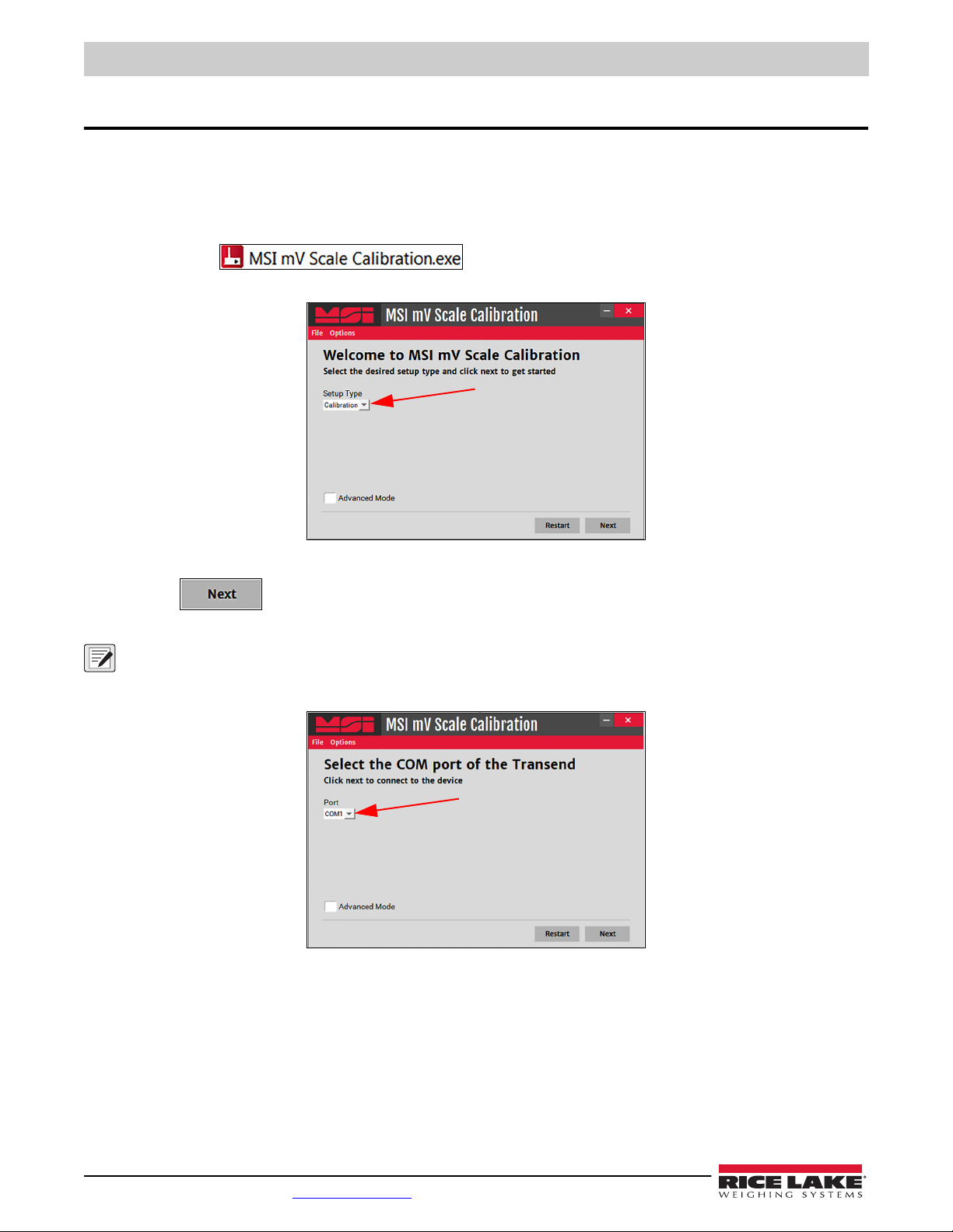
4.0 MSI mV Scale Calibration
Use the following instructions to calibrate an MSI TranSend 7000 Series receiver unit. The MSI mV Scale Calibration software
can be downloaded from the Rice Lake Weighing Systems website.
1. Power on the transmitter and receiver units.
2. On the connected computer, navigate to the MSI mV Scale Calibration
3. Double click .
4. Select Calibration from the drop-down menu.
program.
Figure 4-1. Calibration
5. Press .
6. Select the COM port the SendIt receiver is connected to from the drop-down menu.
NOTE: All other terminal windows must be closed (ScaleConnect/Tera Term).
If no Com Port selection is available, ensure the serial cables are properly connected, the drivers are installed properly and
that the SendIt Pair is powered up. Once an acceptable connection has been made, restart the calibration program.
Figure 4-2. COM Port Selection
46 Visit our website www.RiceLake.com

MSI mV Scale Calibration
7. Check the Advanced Mode dialogue box to change the upper and lower range percent detected by the SendIt
system, if necessary.
Figure 4-3. Advanced Mode
8. Press .
9. Enter the total scale capacity.
10. Press .
11. Remove all weight from the scale.
12. When scale is stable, press .
Figure 4-4. Scale Capacity
Figure 4-5. Zero Calibration
© Rice Lake Weighing Systems ● All Rights Reserved 47

MSI TranSend 7000 Series
Figure 4-6. Span Calibration
13. Load test weights onto the scale.
14. Enter the appropriate weight value in the weight dialogue box.
15. Press .
Calibration Complete displays.
Figure 4-7. Calibration Complete
16. Press to return to the calibration start display.
17. Calibrate the indicator, see the indicator manual for instructions.
48 Visit our website www.RiceLake.com

Optional Rugged Remote
5.0 Optional Rugged Remote
The MSI-7000 with an installed RF modem can be controlled with an optional Rugged Remote. The Rugged Remote is a
transmit only device that can be used to perform basic scale functions. The range may vary up to 100' or more depending on
room conditions and line of sight.
The RF modem in the MSI-7000 must be configured to accept communication from the Rugged Remote, contact Rice Lake
Weighing Systems for pairing requirements.
NOTE: A Rugged Remote is paired to an individual device and cannot be reprogrammed in the field.
Figure 5-1. Rugged Remote
5.1 Operation
The Rugged Remote is paired to a single ScaleCore RF device and replicates the front panel buttons. Slight variations between
each device's buttons will result in different operation in the Rugged Remote. See Table 5-1 for corresponding buttons for the
Rugged Remote and the connected device.
NOTE: The Rugged Remote can only be paired to a single ScaleCore device. Reprogramming to configure communication
to a different ScaleCore device can only be performed at the factory or with the purchase of additional RF modems.
Rugged Remote Description
Power
Zero
Tare
Function
Table 5-1. Corresponding Buttons
© Rice Lake Weighing Systems ● All Rights Reserved 49

MSI TranSend 7000 Series
5.1.1 Power
The Rugged Remote can be enabled to turn on and off the ScaleCore device it is paired remotely. The hold function must be
enabled.
NOTE: The Hold feature causes the device's modem to stay on and continuously draw from the battery, even when the
device is turned off, resulting in decreased battery life.
5.1.2 Zero
Press to remove small deviations in zero when the scale is unloaded.
This key is not programmable.
5.1.3 Tare
Press to tare the scale.
5.1.4 Programmable Function Keys
and are programmable in the scale. Function is defaulted to Test. See scale manual to configure the function
key for Rugged Remote operation.
5.2 Conflict and Jamming Considerations
It is important to understand that only one transmitter at a time can be activated within a reception area. While the transmitted
signal consists of encoded digital data, only one carrier of any frequency can occupy airspace without conflict at any given time.
This is not to say that there cannot be multiple remote controls for the unit, but rather that two cannot be used simultaneously.
5.3 FCC Compliance
The Rugged Remote has 802.15.4 certification (Section 2.8 on page 19).
50 Visit our website www.RiceLake.com

6.0 Specifications
Power
MSI-7000: 5-6 VDC, 7-36 VDC, 85-265 VAC
MSI-7001: 5-6 VDC, 7-36 VDC, 85-265 VAC
MSI-7000HD: 7-36 VDC, 9-36 VDC, 85-265 VAC
MSI-7001HD: 5-6 VDC, 7-36 VDC, 9-36 VDC, 85-265 VAC
Excitation Voltage
Transmitter: +4.8 VDC, 16 x 350 ohm or 32 x 700 ohm load cells
Standard Antenna
1/2 wave 2dBi, articulated
Frequency
Direct sequence spread spectrum at 2.4 GHz, 802.15.4
Effective Range
Typically 100 to 300 ft, line of sight; for longer range consult factory
Communication Ports
Full duplex RS-232
Specifications
Circuit Protection
RFI, EMI, ESD protection
Operating Temperature
-40 °F to 185 °F (-40 °C to 85 °C)
Rating/Material
MSI-7000 TranSend: NEMA Type 4 (IP65), aluminum black powder coated (excludes wall cube model)
MSI-7001 TranSend: NEMA Type 4 (IP65), aluminum black powder coated (excludes wall cube model)
MSI-7000HD/MSI-7001HD: IP66, Milled Anodized Aluminum
Additional RF Options
Wi-Fi
802.15.4
FHSS
Warranty
One-year limited
© Rice Lake Weighing Systems ● All Rights Reserved 51

MSI TranSend 7000 Series
52 Visit our website www.RiceLake.com


230 W. Coleman St. • Rice Lake, WI 54868 • USA
U.S. 800-472-6703 • Canada/Mexico 800-321-6703 • International 715-234-9171 • Europe +31 (0)26 472 1319
© Rice Lake Weighing Systems Specifications subject to change without notice.
www.ricelake.com
PN 167375 Rev EApril 19, 2023
 Loading...