

Page 1
Page 2

Page 3

Table of Contents
1 INTRODUCTION ............................................................................................ 1
2 DEVICE CONFIGURATIONS ....................................................................... 1
2.1 M2000 DESKTOP .................................................................................................. 1
2.2 M2000 SLIMLINE ................................................................................................... 2
2.3 M2000 NEMA ...................................................................................................... 2
2.4 ON-BOARD WEIGH CENTER .............................................................................. 3
2.5 ON-BOARD COMPACT WEIGH CENTER .......................................................... 4
3 GENERAL OPERATION ................................................................................ 6
3.1 KEYPAD FUNCTIONS KEYS .................................................................................. 6
3.1.1 On/Off Key ............................................................................................................... 6
3.1.2 ZERO Key ................................................................................................................. 7
3.1.3 TARE Key .................................................................................................................. 7
3.1.4 CLEAR Key ................................................................................................................ 7
3.1.5 PRINT SELECT Key ............................................................................................... 7
3.2 SPECIAL KEYPAD FUNCTIONS ............................................................................. 8
3.2.1 Selecting scale channels ....................................................................................... 8
3.2.2 Summing channels in TOTAL mode ................................................................. 8
3.2.3 Scan mode ................................................................................................................ 9
3.2.4 Gross/Net .................................................................................................................. 9
3.2.5 Pound/Kilograms selection ................................................................................... 9
3.2.6 TEST display............................................................................................................. 9
4 APPLICATION PARAMETER SETTINGS ................................................ 10
4.1 ON-BOARD SCALE SETTINGS ........................................................................... 10
4.2 MULTIPLE ANIMAL SCALE SETTINGS ................................................................. 12
5 CALIBRATION AND SEALING .................................................................. 13
5.1 PLACING THE INDICATOR INTO CALIBRATION MODE .................................. 13
5.1.1 Special Keypad function keys during calibration ........................................ 13
5.1.1.1 Selecting a calibration parameter. ........................................... 13
5.1.1.2 Editing a calibration parameter. ............................................... 13
5.1.1.3 Canceling a calibration parameter. ......................................... 14
5.1.1.4 Toggle between weight and AD counts. ............................... 14
5.1.1.5 Exiting Calibration Mode........................................................... 14
5.2 CALIBRATING WITH WEIGHTS.......................................................................... 15
5.2.1 Set the Scale Parameters ................................................................................... 15
5.2.2 Balance the Scale ................................................................................................. 15
5.2.3 Deadloading the Scale (scale zero) ................................................................ 21
5.2.4 Spanning the indicator ........................................................................................ 21
5.3 SEALING THE INDICATOR ................................................................................... 21
5.3.1 Electronic Seal ....................................................................................................... 21
5.3.2 Audit Trail ............................................................................................................... 21
5.3.3 Accessing the Audit Trail .................................................................................... 22
6 WEIGH CENTER CIRCUIT BOARD .......................................................... 23
6.1 SETTING TIME AND DATE .................................................................................. 26
6.2 SETTING UNITS ................................................................................................... 27
Page 4

1
6.3 SETTING SYSTEM ID NUMBER .................................................................. 27
Copyright © 2011 Rice Lake Weighing Systems. All rights reserved.
Printed in the United States of America.
Specifications subject to change without notice.
November 2011
6.4 STANDARD DIP SWITCH SETTINGS ................................................................. 28
7 PRINTERS ....................................................................................................... 29
7.1 TICKET PRINTER .................................................................................................. 29
7.2 ROLL PRINTER ..................................................................................................... 30
8 M2000 INDICATOR PARAMETER LIST .................................................... 31
8.1 CAL INITIALIZATION PARAMETERS ........................................................... 31
8.2 SCALE SETUP PARAMETERS ............................................................................ 31
8.3 SCALE MOTION PARAMETERS ........................................................................ 32
8.4 SCALE ZERO PARAMETERS ............................................................................... 32
8.5 PARAMETERS RELATED TO SCALE CALIBRATION ..................................... 33
8.6 INDICATOR POWER UP PARAMETERS ...................................................... 34
8.7 SCALE TARE PARAMETERS ................................................................................ 35
8.8 SYSTEM SETTINGS PARAMETERS .................................................................. 35
8.9 SERIAL COMMUNICATIONS PARAMETERS .............................................. 36
8.10 SCALE FILTERING PARAMETERS ......................................................................... 38
8.11 PRINTING PARAMETERS .................................................................................. 39
M2000 INDICATOR LIMITED WARRANTY .................................................... 43
FOR MORE INFORMATION ............................................................................... 44
Web Site ............................................................................................................. 44
Contact Information ........................................................................................ 44
Page 5
1
1 Introduction
This manual covers the complete line of the scale instrumentation based on the
M2000 digital indicator, formally manufactured by Norac Systems International.
The list of instrument configurations, along with their part numbers that are
covered by this technical manual are shown in section 2.
Please take the time to read this manual completely through before contacting
Rice Lake Weighing Systems for further technical assistance. If you have any
questions or comments please contact Rice Lake Weighing Systems:
Phone (toll free): 1-800-472-6703
2 Device Configurations
To identify the device you are dealing with, look for a part number on the
unit’s serial plate. The pictures in this section will help identify the various
devices.
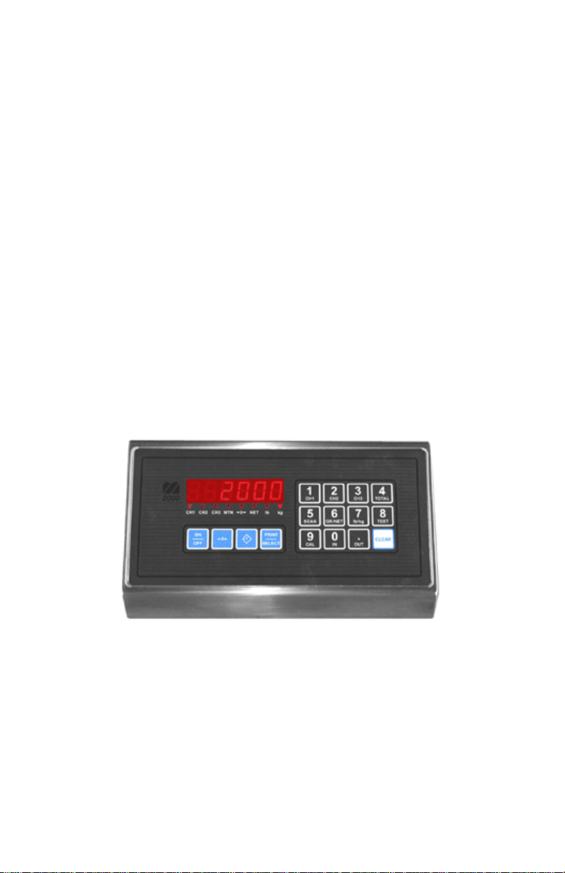
2.1 M2000 Desktop
Part Number: 82-M2000A-DT
Page 6
2
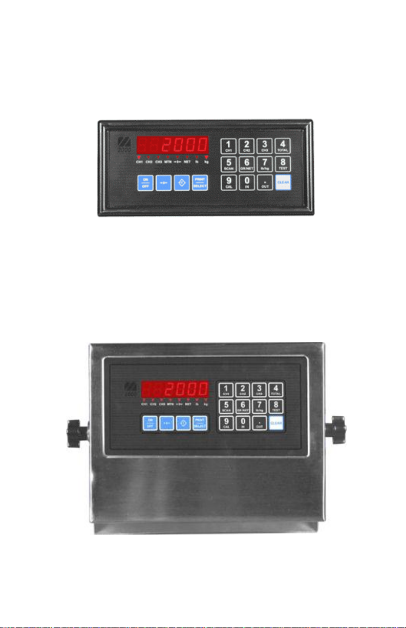
2.2 M2000 Slimline
Part Number: 82-M2000A-SL
Note – this part is used in the On-Board Weigh Center (see section 2.4).
2.3 M2000 NEMA
Part Number: 82-M2000A-NEMA
Page 7
3
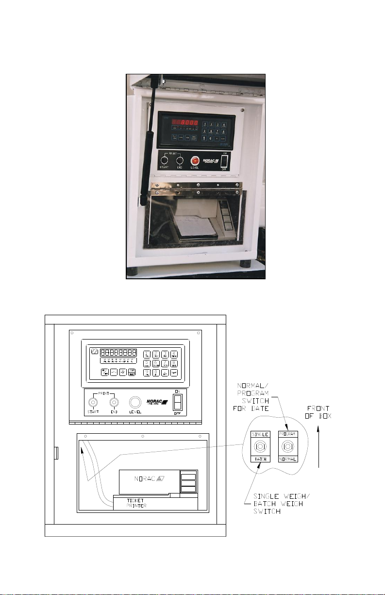
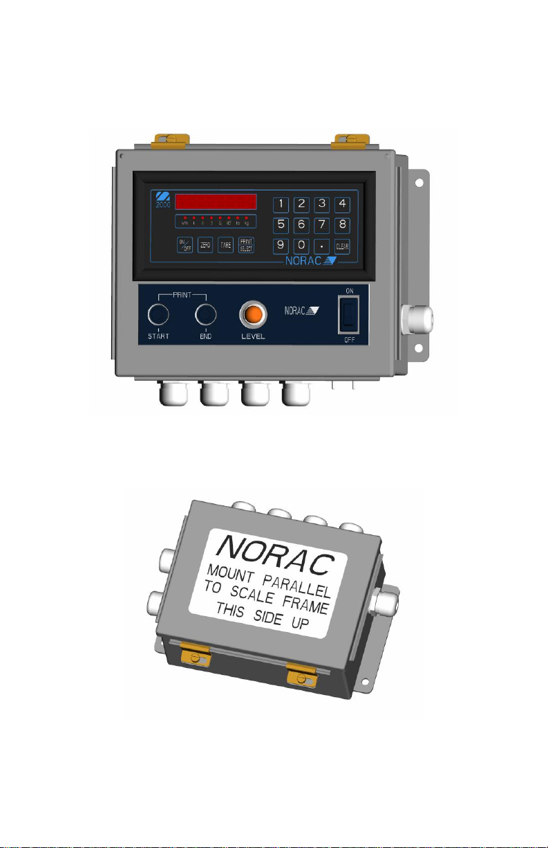
2.4 On-Board Weigh Center
2000
Part Number: 42300, 42300M
Indicator, On-Board Circuit Board and Printer are all housed in the Weigh
Center.
Page 8
4
2.5 On-Board Compact Weigh Center
Part Number: 42301
Cab Mounted Indicator Housing
Level Switch and Load Cell Sum Box (Scale Frame Mounted)
Page 9

5
M2000 Instrument Specifications
Power requirements: 12VDC 1A.
Temperature range: 14°F to 104°F (-10°C to +40°C).
Full scale input signal: 4 ranges: 0-9mV, 0-19mV, 0-39mV and 0-79mV.
Excitation voltage: 7.5VDC, 16x350 Ohm and 32x700 Ohm for all 3 channels combined.
Sense amplifier: Differential amplifier with 4 and 6 wire.
A/D internal resolution: 520,000 counts in both positive and negative direction.
A/D Sampling rate: 100 times a second on each channel.
Span stability: 2ppm/°C.
Zero stability: 5nV/°C.
Linearity correction: 10 span entries.
Calibration method: Calibration through software stored to flash memory.
Calibration sealing: Physical seal or class 1 audit trail system, password protected.
RFI protection: Filtered signal, excitation and sense lines.
Analog output: Optional 4-20mA board via SMART WIRE.
Serial communications: 2 full-duplex RS232/RS422 ports.
I/O interface: Peripheral expansion through SMART WIRE multi drop RS485 port.
External I/O: Up to 6 channel set point board via SMART WIRE.
Set points: 6 programmable set points.
Digital filtering: Adjustable filter parameters with FAST STEP quick response algorithm.
Display modes: Weight can be displayed from CH1, CH2, CH3 and as TOTAL of all
channels.
Tare: Keyboard and scale tare, multiple tare IDs can also be stored in memory.
Time/Date: Y2K compliant time/date clock, internal battery back up.
Truck database: Capable of storing 15-0 truck IDs with associated tare weights.
Truck in/out loop: program for weigh-in and weigh-out applications.
Unit’s conversion: lb/kg.
Zero tracking: 1-99% of 1d, 1d, 2d or 3d.
Ticket editor: Create custom tickets for any serial printer, indicator can store and recall
different tickets.
Enclosure dimensions: SL=9"x4"x1", DT=9.75"x6"x2.5", NSS=10"x7.5"x3".
Approvals: NTEP Class III/IIIL 10000, Measurement Canada Class III 10000 and IIIHD 20000
Page 10
6
2000
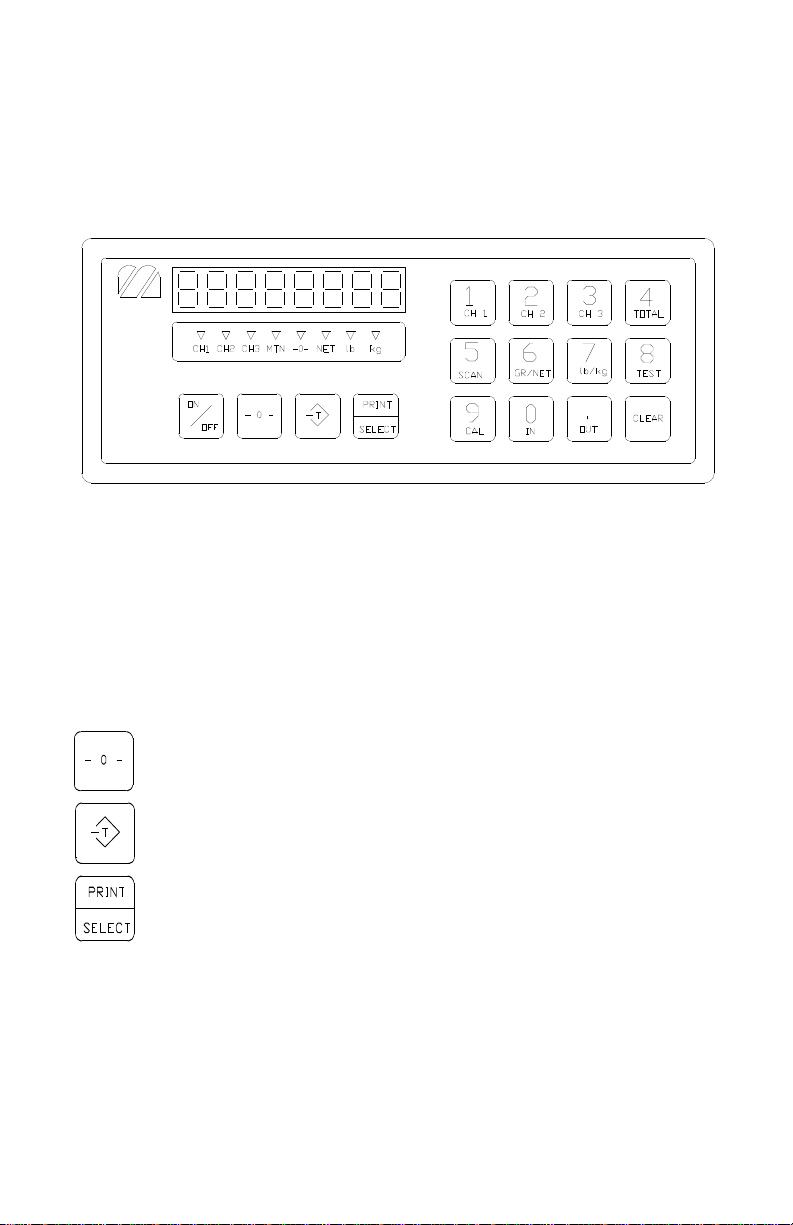
3 General Operation
The layout of the M2000 indicator is shown below.
3.1 Keypad Functions Keys
The M2000 has several function keys, all of which are selected via the front
panel. The function key operations are discussed below. All the keys have
audio feedback when a key is pressed. The sound volume can be set in
calibration mode.
A description of the important keys and buttons are as follows:
Indicator [ZERO] Key
Indicator [TARE] Key
Indicator [PRINT/SELECT] Key
3.1.1 On/Off Key
This is the ON/OFF button for the indicator. Pressing the switch once turns
on the indicator. To turn off the indicator press the switch for 1 second. It is
important to note that there is a power bypass switch option flag that can be
set in calibration (parameter 10). If power bypass is enabled the indicator will
always be on and cannot be turned off via the ON/OFF button. This option
Page 11

7
should be used if the indicator is used in process control applications where
the indicator must power up running after a power outage.
When the indicator starts “m2000" will scroll across the screen followed by
the version number of the software. The indicator performs a full diagnostic
of its internal circuits and will display any error messages if there is an
internal problem with the indicator.
When the indicator is in calibration mode this key can be used to toggle
between displayed weight and AD converter internal counts.
3.1.2 ZERO Key
This key is used to zero the indicator. The scale cannot be zeroed if there is
motion on the scale or the weight on the scale is out of the zero range.
Three quick beeps will sound from the indicator if the zero key is unable to
zero the indicator.
This key also functions as a ZERO key when the indicator is in calibration
mode.
3.1.3 TARE Key
This key is used for taring weight on the scale. A tare can also be entered
from the keypad. To tare from the scale simply press the tare key and what
ever the weight on the scale will be tared. The NET indicator light should be
illuminated showing that the indicator is in net weight display mode.
To manually tare from the keypad enter the weight using the numeric keypad
followed the tare key. The indicator will only accept a tare from a stable and
valid positive weight.
An invalid tare will cause error message 41 to be displayed. Pressing the tare
key will always overwrite any previously stored tare weight. Use the clear key
to clear the tare weight.
It is important to note that the tare key can be disabled in the calibration
menu using parameter 50.
3.1.4 CLEAR Key
This will clear any previously entered tare values entered using the tare key.
Clear will also function as an escape key to cancel any key entry operations.
3.1.5 PRINT SELECT Key
Print select is a dual function key. Pressing the key will cause a ticket to be
printed to a connected printer. If you have typed a numeric value from the
keyboard followed by the PRINT SELECT key then the key acts as a function
select key. More information on this will be discussed below.
Page 12

8
3.2 Special Keypad Functions
Keypad functions are selected by entering a numeric function code on the
keypad followed by the PRINT SELECT key. Some functions are marked on
the key itself. The most common functions are discussed below.
3.2.1 Selecting scale channels
The M2000 has three independent scale channels. Press the channel number
followed by the PRINT SELECT key as shown below.
To select channel 1 press 1 followed by the print select key.
To select channel 2 press 2 followed by the print select key.
To select channel 3 press 3 followed by the print select key.
Note: that by default only channel 1 is enabled. To enable channels 2 and 3 you
must enter calibration mode and use parameter 98 to enable them. Trying to select
a scale channel that is not enabled will display error message 40.
3.2.2 Summing channels in TOTAL mode
Up to 3 channels may me summed together to display a total weight. An
example of an application that may require this operation would be a truck
scale with three sections. Each section would be a separate channel on the
indicator allowing the operator to simultaneously record the total weight of
the vehicle along with the individual axle weights of the truck.
To enter total mode press 4 followed by the print select key. Total mode
must be enabled before it can be used. Parameter 70 in calibration mode is
used to enable the total mode function. Enter 1 followed by the TARE key to
enable TOTAL mode. Total mode cannot be used for legal for trade
applications in Canada. Only channels that are enabled and calibrated with the
same grad size, decimals and units of weight will be displayed in total mode.
Total mode is indicated by illuminating more than one channel on the channel
indicators. Channel 1 is always part of the total.
Example:
Ch1 and 3 are calibrated as 2000 x 2 lbs and Ch2 is calibrated to 500 x 0.2 lb.
When you press 4 followed by the PRINT SELECT key the CH1 and CH3
indicators will illuminate showing that the weight on the display is the sum of
these two channels. Channel 2 however is excluded from the total as it is
calibrated in 0.2d instead of 2d for channels 1 and 3.
When the indicator is in TOTAL mode all the channel operations are
combined. Pressing the ZERO button will zero all the channels that are part
of the total. The TARE function will tare all channels simultaneously displaying
the total net weight. The motion indicator and center of zero indicators will
Page 13

9
indicate the status of all the scales that are part of the total. For example
scale 1 may be at the center of zero, but channel 3 might not be at zero. The
center of zero indicator would then not illuminate reflecting that we are not
at zero.
To set the indicator back to single channel mode, select a channel followed
by the print select
3.2.3 Scan mode
Scan mode allows the indicator to cycle between the scale channels that are
enabled. The indicator will automatically switch the display to the next
available channel and pause for 3 seconds before switching to the next
channel. To stop scanning press a channel key followed by the print select
key.
To enter scan mode press 5 followed by the print select key.
3.2.4 Gross/Net
Pressing 6 followed by the print select key switches between displayed net
weight and gross weight.
3.2.5 Pound/Kilograms selection
To change the displayed units on the display press 7 followed by the print
select key. The indicator will toggle the displayed units on the display from lbs
to kgs or kgs to lbs. The units that the indicator uses as a default when
turning on the indicator is determined by the power up setting set in
calibration.
3.2.6 TEST display
To test the display segments press 8 followed by the print select key. All the
segments in the display will light up for a short period of time.
Page 14

10
4 Application Parameter Settings
M2000
Parameter
Value
2 0 5
2
8 0
9 0 10
1
11
3
19 1
21
2
22
0
23
15
24
16
30
3* 31
0
34
3
38
0
40
0
41
100
42
12 43
8
44
0
50 1
65
2
Parameters not listed in the table should be set to their factory default values.
For factory defaults, see section 8.
4.1 On-Board Scale Settings
Table 1 – On-board Parameters
Parameters 3 and 4 will vary depending on application see the table below for
the proper values of each.
** Set Parameter 6 power on units to 1 for Kg or 0 for lbs.
*** Set Parameter 30 to 3 for Ticket Printers or 6 for roll printer (Also see
printer section)
Page 15

11
M2000
Parameter
Number
Net Capacity x Divisions
8000 x 2 kg
12,000 x 2 kg
15,000 x 5 kg
3 2 2
5
4**
8400
12600
15750
6 1 1
1
M2000
Parameter
Number
Net Capacity
10,000 x 2 lb
20,000 x 5 lb
60,000 x 10 lb
3 2 5
10
4**
10500
21000
63000
6
1 kg
0
0
Table 2 - Parameter Settings (Metric units)
Table 3 - Parameter Settings (US units)
Notes:
* Set parameter 30 to 3 for ticket printers. Set parameter 30 to 6 for roll
printers.
** Values listed are maximum settings. Parameter 4 may be set anywhere from
net capacity plus one division up to the maximum setting.
Page 16

12
M2000 Parameter
Number
MMAS Model
7-13
(all lengths<14 Ft)
MMAS Model
7-20
(all lengths>14 Ft)
2 0 0
3
2 kg
(5 lb)
2 kg
(5 lb)
4
6900 kg
(15200 lb)
9100 kg
(20060 lb)
5 4 4
6 0 0 8 1
1
9 0 0
10 1 1
11 3 3
19 0 0
21 2 2
22 0 0
24 8 8
25 0 0
30*
3 (ticket printer)
6 (roll printer)
3 (ticket printer)
6 (roll printer)
34 3 3
38 0 0
41
200
200
42 5 5
43
20
20
44 1 1
50 0 0
4.2 Multiple Animal Scale Settings
TABLE 4.0 - M2000 Parameter Settings Multiple Animal Scale
*Also see printer section
Page 17

13
5 Calibration and Sealing
To calibrate a scale the indicator must be placed in calibration mode. Only
qualified scale technicians should be performing these operations. The 3 scale
channels are independent of each other and must be calibrated separately.
5.1 Placing the indicator into Calibration Mode
To calibrate channel 1 press 19 followed by the print select key.
To calibrate channel 2 press 29 followed by the print select key.
To calibrate channel 3 press 39 followed by the print select key.
Note that standard On-Board and Mobile Multiple Animal applications use
single channel indicators. Channels 2 and 3 are not available.
The display will be showing a blinking “PASS” message. This prompts you to
enter a 4 digit password. Key presses are not displayed on the display. If the 4
digit password sequence is correct then the indicator will automatically enter
calibration mode.
The factory default for the password is 1111. This can be changed but we
recommend keeping the password to the factory default, more on this later.
You have 30 seconds to enter calibration mode before the indicator cancels
and returns back to normal weighing mode.
Calibration mode is indicated when there is a blinking ‘C’ displayed in the left
most digit on the display.
5.1.1 Special Keypad function keys during calibration
5.1.1.1 Selecting a calibration parameter.
The M2000 uses parameter numbers to access calibration functions. Each cal
function has a unique number used to access that parameter. In calibration
mode the print select key now becomes the calibration function select key.
Entering a calibration function number followed by the print select key selects
a calibration parameter to edit. Immediately after a function parameter has
been entered followed by the print select key the value of that parameter will
be displayed on the display for a short period of time.
5.1.1.2 Editing a calibration parameter.
After selecting a cal parameter with the print select key a new value for that
cal function can be entered. The TARE key now becomes an ENTER key for
entering calibration parameters. Parameter values entered from the keypad
must immediately follow with the TARE key to take affect.
Page 18

14
5.1.1.3 Canceling a calibration parameter.
If you would like to cancel a calibration function you can use the CLEAR key
as an ESCAPE key. This key will get you out of most calibration operations.
5.1.1.4 Toggle between weight and AD counts.
A unique feature of the M2000 is the ability to toggle between weight and the
AD converters internal counts. This can be an excellent diagnostic tool for
the experience scale technician. Pressing the ON/OFF key will show the
internal AD counts. The blinking ‘C’ will now change to a blinking ‘A’ to
indicate analog AD counts are being displayed. Press the ON/OFF button
again to switch back to weight mode.
5.1.1.5 Exiting Calibration Mode.
To exit calibration mode press 99 followed by the print select key. All
calibration parameters will be saved and the indicator will restart in weighing
mode. Note: Channels 2 and 3 are disabled by default. Remember to enable
them before exiting calibration mode by using parameter 98.
Page 19

15
5.2 Calibrating with Weights
A complete calibration of the scale would include all the steps described in
this section in order: set the parameters, balance the scale, deadload the
indicator, and set the span.
5.2.1 Set the Scale Parameters
Set or verify all the parameter settings for your application. Refer to section 4
for details on the settings for common applications.
5.2.2 Balance the Scale
When loading test weights on the scale (for balancing or calibration), it is
important to position the weights correctly for your application. Imagine lines
connecting the load cell positions (see below). Keep the weights inside the area
defined by the lines connecting the load cell positions. The loading area for a
typical On-Board system is shown below.
Typical Loading Areas
Page 20

16
1. Before the scale can be calibrated, all load cells must be balanced and
responding to loading equally by adjusting the balance trimmers. If you
have a weigh center, the balance trimmers are located on the main
circuit board, inside the control panel. If you do not have a weigh center,
your balance trimmers will be located inside a junction box on the scale.
All trimmers are initially set to 2-Ohm resistance. Use the following
procedure to balance the load cells.
2. Use proper balancing weights to ensure good balancing. Use a minimum
of ¼ of the net capacity of the scale for balancing. I.e. for a 10,000-lb net
capacity, use at least 2500 lbs. for balancing. However, be careful not to
exceed the capacity of the individual load cells.
3. Activate the scale so that the platform is live. Load weights to the full
capacity of the scale: then, unload all the weights. This process
“exercises” the load cells.
4. Press the zero key to obtain a good center of zero. Load one cell by
placing the balancing weights on that corner of the scale (inside the
loading area). Keep the weights as close to the cell as possible directly
above the cell being preferred. Record the weight on the M2000.
5. Repeat step 4 for the other cells with the same procedure (remembering
to press the zero key to obtain a good center of zero). All the readings
should be within approximately one percent (1%) of each other. If the
readings are significantly farther apart, you may not be able to balance
your system. Contact Rice Lake Weighing Systems for technical
assistance.
6. Pick the lowest reading and adjust the other cells down to this value with
the trimmers inside the control box. To adjust a cell use the following
procedure:
7. With no test weights on the scale, press the zero key to obtain a good
center of zero
8. Load the balancing weight over the cell to be adjusted.
9. If you have to adjust the cell by one or two graduations, simply turn the
trimmer clockwise to reduce the displayed reading to the desired
reading. Make sure you are adjusting the appropriate trimmer. Typical
load cell numbering conventions are shown below.
10. If you have to adjust the cell by more than one or two graduations, the
system may undergo a zero shift during the adjustment. Adjust the cell
(by turning the trimmer clockwise) to one graduation LOWER than the
desired value. Remove the weights and check the zero. Re-zero the scale
and repeat the process until the desired reading is obtained.
Page 21

17
11. Test the final balance by loading each cell again and recording the M2000
readings. The cells must read within one graduation of each other for an
acceptable final balance. However, it is more desirable that there be no
difference in the readings (zero balance error).
12. The system can now be spanned.
Page 22

18
EXAMPLE: OB30L-F3 System
English Units (lbs.)
Cell
Metric Units (kg)
M2000 Reading
M2000 Reading
Start
Loaded
Unloaded
Start
Loaded
Unloaded
0
4995
0 1 0
1998
0 0 4990
0 2 0
1996
0
0
5005
0 3 0
2002
0
English Units (lbs.)
Cell
Metric Units (kg)
M2000 Reading
M2000 Reading
Start
Loaded
Unloaded
Start
Loaded
Unloaded
0
4990
0 1 0
1996
0 2
3
English Units (lbs.)
Cell
Metric Units (kg)
M2000 Reading
M2000 Reading
Start
Loaded
Unloaded
Start
Loaded
Unloaded
1
2 0 4985
-5 3 0
1994
-2
English Units (lbs.)
Cell
Metric Units (kg)
M2000 Reading
M2000 Reading
Start
Loaded
Unloaded
Start
Loaded
Unloaded
0
4990
0 1 0
1996
0
0
4990
0 2 0
1996
0
0
4990
0 3 0
1996
0
Balancing Weights: English = 5000 lb. Metric = 2000 KG
Graduations: English = 5 lb. Metric = 2 KG
First Loading
From the above results, it can be seen that cells 1 and 3 must be adjusted down
to read 4990 lbs. (1996 kg in the metric example). First, the trimmer for cell 1
is turned clockwise to bring the reading down (step 6(c)).
Second Loading
Next, the trimmer for cell 3 is turned clockwise to bring its reading down.
Because this cell is being adjusted by three graduations, the procedure in 6(d)
should be followed, adjust cell 3 down to 4985 lbs. (1994 kg in the metric
example) and check for a zero shift.
Third Loading
The unloaded reading is found to be –5 lb (-2 kg), indicating a zero shift. The
scale must therefore be re-zeroed, and cell 3 checked again.
Fourth Loading
THE CELLS ARE NOW BALANCED WITHIN THE TOLERANCE OF ONE
GRADUATION.
Page 23

19
Standard Load Cell Numbering, Cell and Trimmer locations –
Multiple Animal Scales
Page 24

20
Standard Load Cell Numbering, Cell and Trimmer locations –
On-Board Scales
Page 25

21
5.2.3 Deadloading the Scale (scale zero)
Before the indicator can be calibrated the deadload or scale zero value must
be obtained. Remove all test weights from the scale. Key parameter 12
followed by the PRINT/SELECT key. The display will show ‘r’ for “reconfirm”.
Press 1 followed by the TARE key to confirm to continue with deadloading
the scale. The indicator will pause for a short duration and then display the
deadload value in AD counts to the display. The indicator will then return
back to weight display mode. The indicator can now be calibrated with a
known test weight.
5.2.4 Spanning the indicator
Place a known test weight on the scale. Enter 13 followed by the
PRINT/SELECT key. The display will briefly flash “1”. Shortly after, the display
will freeze with the last displayed weight. Enter the value of your test weight
followed by the TARE key. The indicator will immediately calibrate and
return back to weight display mode. If the display shows “EEEEEE” then you
have exceeded the scale capacity value set in parameter 4 and 8. If the display
shows “AAAAAA” then you have exceeded the input analog range of the
indicator. The output voltage from the load cells exceeds the input for the
AD converter.
Once the proper weight is displayed, exit calibration mode by pressing 99
followed by the PRINT/SELECT key.
5.3 Sealing the indicator
The M2000 is sealed electronically with a password. There is also provision
for physical sealing on all products. The 42300 and 42300M have faceplate
screws that accommodate a wire and lead seal.
5.3.1 Electronic Seal
Passwords are 4 digit numbers. The factory default for the password is 1111,
which can be changed in calibration mode. To change or view the password
in calibration mode use parameter 96. Enter a 4 digit password followed by
the TARE key. Important note: if you forget your password you will not be
able to enter calibration mode on the indicator. Contact the factory for
assistance at 604-941-3474.
5.3.2 Audit Trail
The M2000 is equipped with a Category 1 Audit Trail system. It is
important that the correct time and date be set, as this is saved as part of
Page 26

22
the audit trail. The audit trail is permanent and cannot be disabled or erased
by removing the internal battery inside the indicator. The Audit Trail has two
counters, the Calibration counter and the Parameter counter. Changing
parameters that affect the calibration of weight will increment the Calibration
counter by 1. All other parameters will increment the Parameter counter.
The counters will count from 000 to 999 before rolling over again. Changing
one or more parameters will only increment the counter by 1 per calibration
session. Only an actual change of value to the calibration parameter will
register to the audit trail.
Important Note:
Because the audit trail becomes active at the factory, the counters may not show 0
even when the indicator is new out of the box.
5.3.3 Accessing the Audit Trail
The audit trail can only be accessed from normal weighing mode and cannot
be accessed while you are in calibration mode. Enter 1000 followed by the
PRINT SELECT. The message “Audit” will briefly be displayed on the display.
Shortly after the indicator will cycles through 3 times displaying the date of
when the last change was made to the indicators calibration parameters, the
calibration (CAL) counter and the configuration (CFG) counter. You may
press the CLEAR key at any time to cancel this operation.
Page 27

23
6 Weigh Center Circuit Board
TO JUNCTION
The weigh center circuit board is located in the weigh center, behind the
indicator faceplate.
Page 28

24
Indicator Wiring, 42300, 42300M
Power Connections On-Board Application
Power Connections Multiple Animal Scale Applications
Page 29

25
Cab Alarm Wiring (On-Board Applications)
Scale Up Alarm (Magnetic Reed Switch) Wiring On-Board
Applications
Page 30

26
6.1 Setting Time and Date
Inside the control panel, in the ceiling of the printer compartment you will find
two toggle switches near the back (See Error! Reference source not
found.). The right toggle switch is a two-position switch (Program switch) that
puts the indicator PROGRAM TIME AND DATE or NORMAL modes. Pull the
program switch ahead to put the system into indicator PROGRAM TIME AND
DATE mode. Push the switch toward the back of the box to resume NORMAL
operation.
1. Pull the program switch into the PROGRAM TIME AND DATE position as
described above.
2. Place a piece of paper into the printer.
3. Enter the desired date into the indicator set point register in a DDMMYY
(Day Month Year) format using the key sequence outlined below. For
example June 16, 2002 would be entered as:
[2][0] [PRINT/SELECT]
[1][6][0][6][0][2] [PRINT/SELECT]
Note: You have a limited amount of time to enter the actual date
keystrokes (about 4 seconds). If the indicator goes back to GROSS mode
before you get the entire date entered you must type
[2][0][PRINT/SELECT] again then enter the date keystrokes.
4. Hold the [START] button until your keystrokes start to be displayed,
about 5 seconds, then release. The indicator will automatically repeat your
keystrokes and the printer will output the following message:
Enter date please:
date received, start to continue
5. Enter the desired time into the indicator set point register in HHMM
(Hours Minutes) format using the key sequence outlined below. The time
must be in a 24-hour format. For example 1:15 PM (13:15) would be enter
as:
[2][0] [PRINT/SELECT]
[1][3][1][5] [PRINT/SELECT]
Note: You have a limited amount of time to enter the actual time
keystrokes (about 4 seconds). If the indicator goes back to GROSS mode
before you get the entire date entered you must type
[2][0][PRINT/SELECT] again then enter the date keystrokes.
6. Press the [START] button briefly once. The indicator will automatically
repeat your keystrokes and the printer will output the following message:
time received, start to continue
7. Press the [START] button briefly once again. The printer will output the
following message:
1606021315 rec’d
8. Push the program switch back into NORMAL position.
Page 31

27
9. End of procedure.
Note: The toggle switch must be in the NORMAL position for
the normal functions of the system to operate.
6.2 Setting Units
Note: To change units, the Weights and Measures seal will have to be
broken. Contact Rice Lake Weighing Systems prior to breaking the seal or
have a qualified scale dealer break the seal. Breaking the seal may violate the
Weights and Measures approval of the scale.
NOTE: If you attempt to change the units through the indicator, the Weigh
Center will automatically switch the units back to the DIP switch setting (see
below).
1. Open the faceplate where the indicator is mounted. To open the faceplate,
remove the two screws at the top of the panel and fold it forward.
2. Inside the control panel there is a circuit board with a small bank of
switches (DIP switches). These DIP switches are located on the front corner
of the circuit board. As shown in the diagram below, the side of the DIP
switch that is down determines if the switch is in the open or closed position.
3. The units can be in kilograms (kgs) or pounds (lbs). To change this setting
find switch #7 and set appropriately.
Closed = kgs Open = lbs
6.3 SETTING SYSTEM ID NUMBER
Supply 14 Volts potential to the circuit board through the Truck Cable. Power
up the M2000.
Open DIP-switch 3 on the circuit board.
Key in 20 <SELECT> and enter in the last three digits of the indicator serial
number, e.g. S/N S0750 key in 750, and press <SELECT>.
Close DIP-switch 3.
Page 32

28
6.4 Standard DIP Switch Settings
Switch #
Position
Description
1
Open
DO NOT CHANGE
2
Closed
DO NOT CHANGE
3
Closed
DO NOT CHANGE
4
Open
DO NOT CHANGE
5
Open
DO NOT CHANGE
6
Closed
DO NOT CHANGE
7
a) Closed
b) Open
a) Kilograms (kgs)
b) Pounds (lbs)
8
Closed
DO NOT CHANGE
Switch #
Position
Description
1
Open
DO NOT CHANGE
2
Closed
DO NOT CHANGE
3
Closed
System ID number
4
Open
DO NOT CHANGE
5
Open
DO NOT CHANGE
6
Closed
DO NOT CHANGE
7
c) Closed
d) Open
c) Kilograms (KGS)
d) Pounds (LBS)
8
Closed
DO NOT CHANGE
The standard DIP switch settings on the main circuit board should be set as
follows:
Mobile Multiple Animal
On-Board
The standard DIPswitch settings on the main circuit board should be set as
follows:
Page 33

29
7 Printers
1 2 3 4 5 6 7 8 9
10
ON
OFF
OFF
OFF
OFF
OFF
ON
ON
OFF
OFF
7.1 Ticket Printer
Epson TM290, TM295
Printer DIP Switch Settings:
For On-Board and Mobile Multiple Animal Applications:
DIP Switch Settings
THE DIP SWITCHES 6 & 8 ON THE WEIGH CENTER CIRCUIT BOARD MUST BE
CLOSED.
Page 34

30
7.2 Roll Printer
1 2 3 4 5 6 7
8
OFF
OFF
OFF
OFF
OFF
OFF
OFF
ON
1 2 3 4 5 6 7
8
OFF
OFF
OFF
OFF
OFF
OFF
OFF
OFF
Epson TM-U200D
Bank #1
Bank #2
The DIP switches 6 & 8 on the Weigh Center circuit board must be OPEN.
Page 35

31
8 M2000 Indicator Parameter List
The following gives a partial list of the M2000 parameters. The list explains the
use of the most commonly needed parameters on the indicator. However, the
M2000 features over 80 parameters. For a complete list contact Rice Lake
Weighing Systems.
8.1 CAL INITIALIZATION Parameters
1 Reload Factory Default Values
This function will reinitialize the indicators scale calibration parameters for the
specific channel to the default factory values. When you have selected his
function you must confirm by pressing [1] followed by the [TARE] key. This will
only initialize a single channel. The indicator will automatically exit calibration
and reboot to initializing the calibration data to factory default. Any other
values will display error 7. The indicator will reboot after performing a factory
reset. Use parameter 260 below to reinitialize completely to factory defaults.
260 Complete factory initialize
Similar to parameter 1 above. This parameter completely initializes all indicator
settings to factory defaults on all 3 channels. This includes COM port settings
and all other system related settings. Ticket data and tares stored in memory
are not initialized.
98 Enables scale channel (0)
This parameter enables scale channels 2 or 3. Channel 1 is always enabled and
cannot be disabled. By default channels 2 and 3 are turned off. To enable a
channel enter 1followed by the [TARE] key. To disable a channel enter 0
followed by the [TARE] key.
99 Exit calibration mode
This parameter will exit calibration mode and restart the indicator. All
calibration changes are stored to flash memory and the audit trail is updated.
8.2 SCALE SETUP Parameters
2 Decimal Point Position (0)
Sets the decimal position for the display. Values 0 to 4 can be entered followed
by the [TARE] key. An invalid entry will display error 3.
3 Graduation size (1d)
Selects the grad size to be used on the scale. Values that can be entered are 1,
2, 5, 10, 20, 50 and 100 followed by the [TARE] key. An invalid graduation size
will display error 2.
4 Scale Capacity (10000d)
This should be set to the scale capacity for the scale. For example if your scale
capacity is1000 lbs then you would enter would be 1000 followed by the
[TARE] key. The zero range window is calculated from this parameter
Page 36

32
8 Scale Over (1d)
Enter the number of divisions for scale over. For example if your scale capacity
is 1000lbs (parameter 4) and you want the scale to indicate scale over at Scale
Capacity + 9dthen the value you would enter would be 9 followed by the
[TARE] key.
20 Scale Over Message
Scale over is displayed as “EEEEEE” on the M2000 display and in the strings. If
you require maintaining compatibility of older Western Scale equipment then
set this parameter to 1. Scale over will now be displayed with the traditional all
eights “888888”.
98 Enables scale channel (0)
This parameter enables scale channels 2 or 3. Channel 1 is always enabled and
can not be disabled. By default channels 2 and 3 are turned off. To enable a
channel enter 0 followed by the [TARE] key. To disable a channel enter 0
followed by the [TARE] key.
99 Exit calibration mode
This parameter will exit calibration mode and restart the indicator. All
calibration changes are stored to flash memory and the audit trail is updated.
8.3 Scale MOTION Parameters
5 Motion Window (2d)
Enter the value to determine the motion sensitivity. A typical value is 2 times
the graduation size. This is set automatically when the grad size changes
(Parameter 3).
24 Motion Settle Time (8)
Displays the number of ¼ second intervals for which Motion will remain
asserted after the scale reading has stabilized within the motion tolerance.
Enter a value 1-255 followed by the [TARE] key. An invalid motion value will
display error 50.
8.4 Scale ZERO Parameters
9 Power ON Zero Scale Message (0)
With this parameter set to 1 the indicator will power up displaying “Zero” on
the display. The operator must Zero the scale before continuing. This must be
set for certain legal for trade requirements. If the parameter is set to 0 the
indicator powers up displaying weight. An invalid parameter entry will display
error 28.
21 Push to Zero Window or Zero Range (2)
This command displays the percentage of scale capacity that can be zeroed by
the zero key. The allowable range is between 0 and 99%. Enter the range
followed by the [TARE] key. An invalid value will display error 5.
22 Auto Zero Tracking ON/OFF (1)
Page 37

33
This command displays the Auto Zero flag value. The value of 1=ON and
0=OFF. To turn auto zero tracking off enter 0 followed by the [TARE] key. An
invalid entry will display error 4.
23 Auto Zero Tracking Window (AZSM) (60)
This command displays the percentage of a graduation that can be tracked off
during zero tracking. Enter the value followed by the [TARE] key. This value
can be the following:
1-99: to track 1 to 99% of d.
100: to track off 1d.
200: to track off 2d.
300: to track off 3d.
To turn off zero tracking use parameter 22 above. Any other value entered will
display error 6.
45 Power up zero IZSM (0)
When this parameter is set to 1 the indicator will zero the scale automatically
on power up. The maximum range the scale will zero on power is set to +-10%
of full scale capacity. If the initial load on the scale exceeds 10% of scale
capacity then no initial scale zero will take place. Enter 1 to enable or 0 to
disable.
8.5 Parameters related to SCALE CALIBRATION
7 Scale Units
Toggles between pounds and kilos. Make sure that you have selected the units
you are calibrating with. If your test weights are in pounds or kilos then make
sure that the scale unit’s illuminator is displaying the correct units.
11 Indicator Load Cell voltage range (39mV)
This parameter adjusts the input range for the scale-input channel. It is
important that the correct range be selected for optimal performance of the
indicator. Use values 1 to 3 to select the following input ranges:
1 for 0 to +-9mV input range
2 for 0 to +-19mV input range
3 for 0 to +-39mV input range
4 for 0 to +-79mV input range.
If the loadcell input voltage exceeds the input range of the indicator the display
will display ‘AAAAAA’ which means “Analog over-range”. Select the next
highest input range to rectify the problem. Only values 1 to 4 can be entered
and any other value will display error 57. It in important to understand that
selecting a lower input range, for example 9mV range does not necessarily
guarantee better performance. The 9 mV range has more amplification that lets
say the 19 mV or 39mV range. You will get more AD counts for sure, but you
are also amplifying noise. This depends on the scale installation. It most cases
the default 39mV or 19mV range will be adequate.
12 Deadload Scale
Page 38

34
Before spanning the indicator for the first time the indicator must be
deadloaded. Ensure that the scale has all test weights removed from the scale
and the scale is stable before performing a deadload. To perform the deadload
function press 1 followed by the [TARE] key. The indicator will perform the
deadload function. After the deadload has completed the indicator will briefly
display the deadload value in AD raw counts before returning to weight display
mode.
13 Set Span
This command is used to span the indicator with a known test weight. Place
the test weights on the scale. When the set span function has been activated
the current displayed weight will be frozen on the display. Using the numeric
keypad enter the known test weight followed by [TARE]. The display should
now show the new weight on the scale. You can cancel a span any time by
pressing the [CLEAR] button before [TARE] is pressed.
99 Exit calibration mode
This parameter will exit calibration mode and restart the indicator. All
calibration changes are stored to flash memory and the audit trail is updated.
8.6 INDICATOR POWER UP Parameters
6 Power On Units (0)
Determines what units the indicator defaults to when the indicator is turned
on. Entering 1 followed by the [tare] key selects Kilograms. Entering 0 selects
Pounds. An invalid entry will display Error 13.
9 Power ON Zero Scale Message (0)
With this parameter set to 1 the indicator will power up displaying “Zero” on
the display. The operator must Zero the scale before continuing. This must be
set for certain legal for trade requirements. If the parameter is set to 0 the
indicator powers up displaying weight. An invalid parameter entry will display
error 28.
10 Power Switch Bypass (1)
This parameter controls the keypad ON/OFF switch for the indicator. Entering
1 for this parameter disables the ON/OFF switch and the indicator can never
be turned off from the keypad. Also when the indicator power is plugged into
the wall the indicator will turn on without pressing the ON button. This should
be used in applications such as control systems where the indicator must
power up running after a power outage. An invalid entry will display error 56.
46 Power up channel select (1)
This parameter will determine what channel to be the default channel at boot
up. This parameter will only be implemented if the calibration values meet the
criteria.
1 channel 1 as default at startup
2 channel 2 as default at startup (if enabled)
3 channel 3 as default at startup (if enabled)
Page 39

35
4 Total mode (if criteria met)
5 Scan mode
70 Enable Total Mode (0)
Using 4 PRINT/SELECT puts the indicator in total mode and sums channels
into a single total. Total mode is disabled by default. Total mode is not legal for
trade in Canada and can only be used in non-legal for trade applications. 0 Total
mode disabled 1 Total mode enabled
8.7 Scale TARE Parameters
25 Offset Value (0)
Allows the entry of tare offset value. At scale zero, the center of zero light will
illuminate, but the weight will be at the tare offset value. Enter the offset weight
followed by the tare key.
26 Offset flag (0)
This command controls the operating mode of the tare offset. Enter the
parameter followed by the [TARE] key. The following values accepted are:
0=Offset Disabled 1=’Legal for trade mode’ – Indicator cannot be put in ‘NET’
mode if no value has been set for tare. If tare has been entered the offset value
is included in the NET display.80=Not “Legal for Trade mode - Allows
gross/net switching at zero value. If NET is selected, the offset value is
subtracted from the displayed gross weight.
50 Tare function mode (1)
This parameter controls how the tare function works on the indicator. The
options available are: 0: disable keyboard and scale tare No tare can be entered
using the keypad or taring off the scale using push button tare. 1: enable both
keyboard and scale tare Both keyboard tare entry and pushbutton tare can be
used. 2: enable pushbutton tare only Taring is only allowed from the scale. 3:
enable keyboard tare’ Tare entry can only be done from the keyboard 71
Force Zero for keyboard tare (0) This parameter checks if the scale is at
zero before allowing an operator to enter a keyboard tare. If the scale is not at
zero when a keyboard tare is entered then error 35 is displayed. Enter 1 to
enable, 0 to disable.
8.8 SYSTEM SETTINGS Parameters
28 Sound volume (2)
This command controls the volume of the internal buzzer. The following values
can be entered followed by the [TARE] key:
0: sound off
1: volume low
2: volume medium
3: volume high
Error Message 51 will be displayed for an invalid entry.
29 Keypress Feedback
Page 40

36
This function will blink the display every time a key is pressed. This gives a
sense of feedback to the end user when a key is pressed. This is especially
handy in noisy environments where the operator may not be able to here the
key beeps from the indicator. Parameters are 0 (off) or 1 (on) followed by the
[TARE] key. Error 32 will be displayed for an invalid entry.
80 Set Time
Time is set out side of calibration mode in normal weighing mode (you must
exit cal mode). This parameter allows you to set the battery backed real time
clock on the indicator. Pressing 80 followed by the [PRINT/SELECT] key will
display the current time on the display. To change the time, enter your new
time as HHMMSS followed by the [TARE] key. Example: to change the time to
9 hours 33 minutes and 30 seconds enter 093330 followed by the [TARE] key.
81 Set Date
Date is set out side of calibration mode in normal weighing mode. This
parameter allows you to change the battery-backed date on the indicator.
Pressing 81 followed by the [PRINT/SELECT] key will display the current date
on the display. To change the time, enter your new time as YYMMDD followed
by the [TARE] key. Example: to change the date to December 14 year 2001
enter 011214 followed by the [TARE] key.
8.9 SERIAL COMMUNICATIONS Parameters
30 baud rate for COM 1 (6)
Changes the baud rate for COM1. Valid parameters are 0-9. An invalid entry
will display error 52.
32 baud rate for COM 2 (6)
Changes the baud rate for COM1. Valid parameters are 0-9. An invalid entry
will display error 52.
0 : 150
1: 300
2: 600
3: 1200
4: 2400
5: 4800
6: 9600 (factory default)
7: 14400
8: 19200
9: 32400
9600 baud is the default baud rate for both ports. Note: only a single COM port
can be used for printing.
31 Parity for COM 1 (0)
Changes the parity setting for COM1. Valid parameters are 0-2. An invalid
entry will display error 53.
Page 41

37
0: No parity
1: ODD parity
2: Even parity.
33 Parity for COM 2 (0)
34 Stringmode for COM1 (99)
The M2000 supports several string output modes through either COM1 or
COM2. Select the string mode from the table below. Use 99 if you are using
the COM port for ticket printing.
1 DF1000
3 DF2000
5 DF2500 mode1
8 DF1500
9 DF2500 mode 6
10 DF2500 mode 7
12 AD4321, AD4323, AD5000
13 Cardinal 708
14 Cardinal 738
19 Toledo & Fairbanks R2500
16 Weightronix 120
17 Consolodated Controls
18 Analogic 5316
99 Set to ticket printer mode
35 Stringmode for COM2 (8)
36 Flow Control for COM1 (0)
Select 0 for none and 1 for Hardware
37 Flow Control for COM2 (0)
38 String output polled mode for COM1 (5)
39 String output polled mode for COM2 (5)
0 selected output string will be continuously transmitted on COM1
1 selected output string will be transmitted on COM1 when the
PRINT/SELECT key is pressed
2 output when the receive data input is at logic low (-9 volts dc). A
string will be transmitted after each sample whenever the receiver
data line is held low – send on break. output when the receive data
input is at logic high(+9 volts dc). A string will be transmitted after
each sample whenever the receiver data line is held high – send on idle
4 output string to COM1 on ‘?’ character received
5 output string to COM1 continuously
47 Serial String Output Routing FOR COM1 (0)
48 Serial String Output Routing FOR COM2 (0)
Parameter 47 and 48 will determine which channel’s weight will be routed the
COM serial port. This parameter will only be implemented if the calibration
values meet the criteria.
0 COM1 serial output string weight a function of current active channel
1 COM1 serial output string locked on channel 1
Page 42

38
2 COM1 serial output string locked on channel 2
3 COM1 serial output string locked on channel 3
4 COM1 serial output string locked on Total mode
8.10 Scale Filtering Parameters
19 Display Update Rate (0)
This parameter will set the LED display update rate. The update rate has
nothing to do with the actual AD converter update rate or filtering. The
parameter may have a value between 0-9. A value of 0 will introduce no delay
in the display update, while a maximum value of 9 will introduce a display
update rate of a 3-second delay. The update rate at a value of 0 is very fast and
the display may appear jittery in some applications. In this case increase the
value of this parameter.
41 Digital Averaging Filter (64)
Changing this parameter changes the mount of averaging performed on the final
weight. This function is used to help filter the scale from vibrations and display
a stable weight. The default setting should be adequate for most installations
however if heavier filtering is required then increase the filter value. Changing
the filter does alter the settling time for the final weight response. Values that
can be entered are 1-255 followed by the [TARE] key. The higher the number
the heavier the filtering. Error 14 is displayed for an invalid entry.
42 Filter Faststep threshold (8)
The filter averaging system has a filter bypass mode called faststep. Faststep
dramatically improves the display response time for a step change in weight.
When the faststep mode is active the digital averaging filter is bypassed
(parameter 41) displaying an instant change in weight. The threshold or the
amount of instant weight change that has to occur before the indicator is to go
into faststep mode is defined by this parameter. This parameter normally does
not have to be changed. Let us look at an example, we have a 500lb-floor scale.
The faststep value is 8. If a 200 pound man jumps on the scale, the scale will go
into faststep mode, bypassing the averaging filter and displaying a quick jump to
200lbs. When the final weight is settling filter averaging is returned back to
normal weight averaging. If you place a 5 pound weight on the scale the faststep
will not kick in and the weight change will be a little slower. How slow the
weight changes to the 5lb load is a function of parameter 41.
43 Fastep Sensitivity (8)
This parameter normally does not need to be changed, and may be removed in
future releases of the software. This parameter controls how sensitive faststep
is to be (see parameter 42). The value entered here indicates how many AD
samples the weight has to change in a row before the faststep filter kicks in.
For example a 200 pound man jumps on a 500 pound scale. The “Faststep
parameter” 42 has been set to 20 and the “Fastep Sensitivity” parameter 43 has
been set to 5. Only when a weight change of more than 20lbs and has occurred
5 samples in a row then the filter averaging will go into fastep
Page 43

39
mode. Increasing this parameter makes the Fastep filter threshold less sensitive.
44 Disable Faststep (0)
This parameter disables the faststep system altogether. The values for
parameter 42 and 43 are ignored and the system runs in weight averaging
mode only. The response time for the indicator is a function of parameter 41.
Some control batching applications may require that faststep be turned off.
8.11 PRINTING Parameters
84 Add new ticket
This parameter appends a new ticket to the end of the ticket buffer. You can
have several different formatted tickets defined, which can be recalled when
needed. A new ticket number is displayed briefly and then the display will
switch over to tick editor mode. If the user does not want to add a new ticket
but start a new ticket from scratch then the ticket buffer can be cleared using
parameter 88.
85 Edit existing ticket
You can edit an existing ticket by entering the ticket number followed by the
[TARE] key. This will put the display in ticket editing mode with the ticket
loaded. You can now modify the ticket.
86 Number of tickets saved in the ticket buffer
This Parameter displays how many tickets that have been saved in the ticker
buffer. Several different ticket formats can be defined and recalled depending
on the weighing operation.
87 Show available space in Custom ticket buffer
This parameter displays how much room you have left for storing ticket
formats. In most cases you never will run out of room as the ticket buffer can
hold 4000 characters used for formatting 1 or more tickets.
88 Clear Custom Ticket buffer
This parameter will erase all custom ticket formats in memory. Press 1
followed by the [TARE] key to confirm to clear the print buffer. All ticket
formatting will be lost.
89 Print specific ticket
Enter the ticket number you want to print followed by the [TARE] key. The
ticket will be printed with the current displayed weight.
100 Delete Truck IN/OUT Database
This command clears the SRAM based truck in out database. The truck in/out
database is SRAM battery backed up and would only be destroyed if the battery
were removed or low while power is removed from the indicator. After
entering the parameter the command should be completed by pressing key one
followed by PRINT/SELECT followed by TARE.
101 Delete Truck IN/OUT Database
This command clears the FLASH memory based truck in/out database. The
truck in/out database is stored in non-volatile FLASH memory and this is the
only way to clear the database. After entering the parameter the command
Page 44

40
should be completed by pressing key one followed by PRINT/SELECT followed
by TARE. There are a total of 6 set points available on the M2000A. Each set
point can be allocated to any of the 3 channels. This parameter will be used to
enter the weight at which the set point will do its evaluation. This value is
channel dependent as far as the lb/kg units are concerned.
Error Messages
1 Invalid parameter number for calibration mode
2 Graduation size invalid
3 Decimal Position Invalid
4 Flag values must be 1 for ‘ON’ and 0 for ‘OFF’
5 Push to Zero Window must be 0-99
6 Zero tracking must be 1-99 or 100, 200, 300.
7 Only 1 will reset parameters
8 Only 1 will reset span table
9 Span exceeds maximum capacity or span to small
10 IZSM value can be 1 for ON and 0 for OFF
11 Test Weight units must be 0=lb or 1=kg.
12 Motion settle time out of range 1-100
13 Power on units may only be 0=lb, 1=kg.
14 Invalid Time entry HH.MM.SS
15 Invalid Date entry YY.MM.DD
16 Motion value is out of range
17 Press tare to increment span table, any other key invalid
18 Press tare to decrement span table, any other key invalid
19 Span table cannot be decremented passed 1
20 Parameter memory write error, indicator requires service
21 Parameter checksum error, Parameters have been lost.
22 Program check fault, indicator requires service
23 Invalid Serial Port speed setting.
24 Invalid Serial Port Parity parameter
25 Cannot increment Span Table any further
26 Entered offset larger than Capacity
27 Invalid String mode for com port
28 Power on Zero warning 0=Off, 1=On
29 Channel enable is 0=Off and 1=On
30 Only 1 will set the deadload
31 Sound Volume can be between 0-3
32 Keypress feedback can be 0=OFF or 1=ON
33 Invalid Com String mode parameter
34 Invalid Com Port Interface value
35 Scale must be at zero before entering a keyboard tare (see parameter 71)
36 Scale not ready to print
37 Channel 1 cannot be disabled
Page 45

41
38 Invalid Print Select Function Number
39 *
40 Scale channel is not enabled
41 Pushbutton Tare is invalid (Over, Motion, or disabled)
42 Keyboard tare available on channel 1 only.
43 Tare greater than capacity
44 Invalid Password number range, can only be 0000-9999.
45 Parameter 1 to enable password, 0 to disable
46 Only a value of 0, 1 or 80 is accepted as a parameter
47 *
48 Invalid Filter value
49 Invalid Filter Fast step value
50 Invalid Fast step Sensitivity
51 Invalid Fast step on/off
52 Invalid Tare Function Parameter 0-4
53 Invalid input for AD voltage range
90 Calibration checksum failed
100 SRAM failure
110 RTC RAM failure
112 Clock Reset
115 Clock Failed
120 Battery flat or does not exists
121 Battery must be removed
130 COM1 loop back test failed
131 COM2 loop back test failed
133 COM driver chip failed
140 FLASH memory erase failed
141 FLASH memory write failed
151 Database CRC failed
152 CAL copy CRC failed
153 Ticket Buffer CRC failed
150 Audit trail CRC failed
154 DPAGE stack overflow
185 SMART wire COM link not responding SmartWire is enabled and is trying
to find devices. This error will occur as a result of not having devices
connected to the Smart Wire port or a bad wire connection. Hit clear to
bypass this error message. To disable smart wire use parameter 59 in weight
mode. Enter 0 to disable smart wire and 1 to enable it again.
186 SMART wire set-point checksum failed
191 Channel 1 AD converter not responding
192 Channel 2 AD converter not responding
193 Channel 3 AD converter not responding
Error message “Cannot Print”
Note: If you try and print and there is motion, or the scale is overweight
then a message will scroll across the display “Cannot Print”.
Page 46

42
Page 47

43
M2000 Indicator Limited Warranty
Rice Lake Weighing Systems (RLWS) warrants that all RLWS equipment and systems
properly installed by a Distributor or Original Equipment Manufacturer (OEM) will
operate per written specifications as confirmed by the Distributor/OEM and accepted by
RLWS. All systems and components are warranted against defects in materials and
workmanship for two years.
RLWS warrants that the equipment sold hereunder will conform to the current written
specifications authorized by RLWS. RLWS warrants the equipment against faulty
workmanship and defective materials. If any equipment fails to conform to these
warranties, RLWS will, at its option, repair or replace such goods returned within the
warranty period subject to the following conditions:
• Upon discovery by Buyer of such nonconformity, RLWS will be given prompt
written notice with a detailed explanation of the alleged deficiencies.
• Individual electronic components returned to RLWS for warranty purposes
must be packaged to prevent electrostatic discharge (ESD) damage in shipment.
Packaging requirements are listed in a publication, Protecting Your
Components from Static Damage in Shipment, available from RLWS
Equipment Return Department.
• Examination of such equipment by RLWS confirms that the nonconformity
actually exists, and was not caused by accident, misuse, neglect, alteration,
improper installation, improper repair or improper testing; RLWS shall be the
sole judge of all alleged non-conformities.
• Such equipment has not been modified, altered, or changed by any person other
than RLWS or its duly authorized repair agents.
• RLWS will have a reasonable time to repair or replace the defective equipment.
Buyer is responsible for shipping charges both ways.
• In no event will RLWS be responsible for travel time or on-location repairs,
including assembly or disassembly of equipment, nor will RLWS be liable for
THESE WARRANTIES EXCLUDE ALL OTHER WARRANTIES, EXPRESSED OR IMPLIED,
INCLUDING WITHOUT LIMITATION WARRANTIES OF MERCHANTABILITY OR FITNESS FOR
A PARTICULAR PURPOSE. NEITHER RLWS NOR DISTRIBUTOR WILL, IN ANY EVENT, BE
LIABLE FOR INCIDENTAL OR CONSEQUENTIAL DAMAGES.
RLWS AND BUYER AGREE THAT RLWS’ SOLE AND EXCLUSIVE LIABILITY HEREUNDER IS
LIMITED TO REPAIR OR REPLACEMENT OF SUCH GOODS. IN ACCEPTING THIS WARRANTY,
THE BUYER WAIVES ANY AND ALL OTHER CLAIMS TO WARRANTY.
SHOULD THE SELLER BE OTHER THAN RLWS, THE BUYER AGREES TO LOOK ONLY TO
THE SELLER FOR WARRANTY CLAIMS.
NO TERMS, CONDITIONS, UNDERSTANDING, OR AGREEMENTS PURPORTING TO MODIFY
THE TERMS OF THIS WARRANTY SHALL HAVE ANY LEGAL EFFECT UNLESS MADE IN
WRITING AND SIGNED BY A CORPORATE OFFICER OF RLWS AND THE BUYER.
the cost of any repairs made by others.
© 2011 Rice Lake Weighing Systems, Inc. Rice Lake, WI USA. All Rights Reserved.
RICE LAKE WEIGHING SYSTEMS • 230 WEST COLEMAN STREET • RICE LAKE, WISCONSIN 54868 •
USA
Page 48

44
For More Information
Web Site
• Frequently Asked Questions (FAQs) at
http://www.ricelake.com/faqs.aspx
Contact Information
Knowledgeable customer service representatives are available 6:30 a.m. 6:30 p.m. Monday through Friday and 8 a.m. to 12 noon on Saturday.
(CST)
• Sales/Technical Support 800-472-6703
• Canadian and Mexican Customers 800-321-6703
• International 715-234-9171
For immediate assistance call toll-free 1-800-472-6703 (Canadian and
Mexican customers please call 1-800-321-6703). If you are calling after
standard business hours and have an urgent scale outage or emergency,
press 1 to reach on-call personnel.
Fax Number 715-234-6967
• US sales and product information at
prodinfo@ricelake.com
• International (non-US) sales and product information at
intlsales@ricelake.com
Rice Lake Weighing Systems
230 West Coleman Street
Rice Lake, WI 54868 USA
Page 49

 Loading...