

Page 1

Tracer AVi
Aviation Baggage Instrumentation
Installation Manual
93633
Page 2

Page 3

Contents
1.0 Introduction.................................................................................................................................. 1
2.0 Installation ................................................................................................................................... 2
2.1 Unpacking and Assembly . . . . . . . . . . . . . . . . . . . . . . . . . . . . . . . . . . . . . . . . . . . . . . . . . . . . . . . . 2
2.2 Mounting the iQube and Remote Display . . . . . . . . . . . . . . . . . . . . . . . . . . . . . . . . . . . . . . . . . . . 2
2.3 Cable Connections . . . . . . . . . . . . . . . . . . . . . . . . . . . . . . . . . . . . . . . . . . . . . . . . . . . . . . . . . . . . . 2
2.4 Load Cells . . . . . . . . . . . . . . . . . . . . . . . . . . . . . . . . . . . . . . . . . . . . . . . . . . . . . . . . . . . . . . . . . . . . 2
2.5 Serial Communications . . . . . . . . . . . . . . . . . . . . . . . . . . . . . . . . . . . . . . . . . . . . . . . . . . . . . . . . . . 3
2.6 Core Module DIP Switches . . . . . . . . . . . . . . . . . . . . . . . . . . . . . . . . . . . . . . . . . . . . . . . . . . . . . . . 3
2.7 Core Module Reset Procedure . . . . . . . . . . . . . . . . . . . . . . . . . . . . . . . . . . . . . . . . . . . . . . . . . . . . 3
2.8 The Power Supply . . . . . . . . . . . . . . . . . . . . . . . . . . . . . . . . . . . . . . . . . . . . . . . . . . . . . . . . . . . . . . 4
2.9 Fuse Replacement. . . . . . . . . . . . . . . . . . . . . . . . . . . . . . . . . . . . . . . . . . . . . . . . . . . . . . . . . . . . . . 4
2.10 Interface Cables . . . . . . . . . . . . . . . . . . . . . . . . . . . . . . . . . . . . . . . . . . . . . . . . . . . . . . . . . . . . . . . 4
2.11 Replacement Parts and Drawings. . . . . . . . . . . . . . . . . . . . . . . . . . . . . . . . . . . . . . . . . . . . . . . . . 4
3.0 PC Configuration .......................................................................................................................... 7
3.1 Introduction to VIRTUi. . . . . . . . . . . . . . . . . . . . . . . . . . . . . . . . . . . . . . . . . . . . . . . . . . . . . . . . . . . 7
3.1.1 Authentication/Authorization System. . . . . . . . . . . . . . . . . . . . . . . . . . . . . . . . . . . . . . . . . . . . . . . . . . . 8
3.1.2 Communication . . . . . . . . . . . . . . . . . . . . . . . . . . . . . . . . . . . . . . . . . . . . . . . . . . . . . . . . . . . . . . . . . 10
3.1.3 Function Keys and Annunciators. . . . . . . . . . . . . . . . . . . . . . . . . . . . . . . . . . . . . . . . . . . . . . . . . . . . . 10
3.1.4 VIRTUi Operations . . . . . . . . . . . . . . . . . . . . . . . . . . . . . . . . . . . . . . . . . . . . . . . . . . . . . . . . . . . . . . . 10
3.1.5 Web Browser-Based Cell Status. . . . . . . . . . . . . . . . . . . . . . . . . . . . . . . . . . . . . . . . . . . . . . . . . . . . . 11
3.1.6 System Requirements. . . . . . . . . . . . . . . . . . . . . . . . . . . . . . . . . . . . . . . . . . . . . . . . . . . . . . . . . . . . . 11
3.2 VIRTUI Configuration. . . . . . . . . . . . . . . . . . . . . . . . . . . . . . . . . . . . . . . . . . . . . . . . . . . . . . . . . . . 12
3.2.1 Downloading to the Tr a c e r A V i . . . . . . . . . . . . . . . . . . . . . . . . . . . . . . . . . . . . . . . . . . . . . . . . . . . . . 12
4.0 Calibration ................................................................................................................................. 13
5.0 Diagnostics ................................................................................................................................ 16
5.1 Diagnostic Tests . . . . . . . . . . . . . . . . . . . . . . . . . . . . . . . . . . . . . . . . . . . . . . . . . . . . . . . . . . . . . . 16
5.2 Diagnostic Setup . . . . . . . . . . . . . . . . . . . . . . . . . . . . . . . . . . . . . . . . . . . . . . . . . . . . . . . . . . . . . . 16
6.0 Specifications............................................................................................................................ 17
Tracer AVi Limited Warranty.................................................................................................................. 18
Technical training seminars are available through Rice Lake Weighing Systems.
Course descriptions and dates can be viewed at www.ricelake.com or obtained by
calling 715-234-9171 and asking for the training department.
© 2007 Rice Lake Weighing Systems. All rights reserved. Printed in the United States of America.
Specifications subject to change without notice.
November 2007
Page 4

Page 5

About This Manual
This manual is intended for use by service technicians
responsible for installing and servicing the
Tracer AVi
single channel diagnostic junction box and bagwell
display.
Authorized distributors and their employees
can view or download this manual from the
Rice Lake Weighing Systems distributor
www.ricelake.com.
site at
1.0 Introduction
The Tracer AVi system consists of three components:
• iQubeTM, a digital programmable junction box
used with an analog load cell. It outputs a
serial string that can be directly input to the
remote display and
• RD-1 remote display, a .8”, six-digit,
seven-segment LED display.
• VIRTUiTM, a PC-based indicator for iQube.
The virtual front panel consists of display and
five-button keypad.
The iQube consists of three boards:
•The connector board provides the physical
connections for the load cell, serial
communications, and power.
•The core module, which plugs into the
connector board, contains the
processor and stores configuration and
calibration data for the
module provides a discrete A/D input and
converts the analog load cell signal to a digital
serial output.
•The 7.5 VDC power supply mounts inside the
enclosure and requires a 115/230 VAC input.
Configuration
The Tra cer AVi system can be configured by using a
PC running the
VIRTUi configuration program. This
method defines the load cell connected to
which is associated with a platform, and the platform
that makes up the scale. Even though the
single-channel
iQube is just one cell, one platform,
and one scale; the association of scale and platform is
required because the software is also used on multiple
cell and multiple platform scales.
Configuration consists of the following steps:
Define Load Cell: This is the electrical sensitivity
(mV/V output) and capacity specification of the load
cell. Load cell name and serial number can also be
specified.
VIRTUi.
Tracer AVi’s
Tracer AVi. The core
iQube,
Some procedures described in this manual
require work inside the iQube enclosure.
These procedures are to be performed by
qualified service personnel only.
The Tracer AVi does not have an on/off switch and therefore
must be installed near a power outlet that is easily accessible
and in accordance with UL/CSA Safety Standards.
Define Platforms: The iQube board must assign a
load cell to the platform.
Define System: The iQube board must assign the
platform to the system.
Load Cell Trimming and Calibration
iQube supports calibration of multiple load cells with
corner match and section match calibration.
For the single cell iQube, only multi-point linear
calibration and theoretical calibration apply. Each type
of calibration captures the initial dead load of the scale
and provides a means to trim the output of the load
cell.
Based on the cell capacity and sensitivity, the
theoretical calibration calculates weight values based
on the total signal from the cell.
Single Cell Diagnostic
Diagnostic functionality can be enabled for the iQube
to identify abnormal load cell output. The diagnostic
conditions that can be identified are open bridge open
channel, drifting, peak-to-peak noise, cell at rail, and
cell over/under range.
Error conditions generate a displayed error message if
connected to
VIRTUi which can be configured to
email the alert message to an address.
Introduction 1
Page 6
2.0 Installation
This section describes procedures for connecting load
cell, power, and serial communications cables to the
TM
iQube
enclosure. Drawings and replac ement parts
lists are included for the service technician.
Use a wrist strap to ground yourself and
!
protect components from electrostatic
discharge (ESD) when working inside the
iQube enclosure.
Disconnect AC power from the main module before installing
remote displays.
2.1 Unpacking and Assembly
Immediately after unpacking, visually inspect the
contents to ensure all components are included and
undamaged. The shipping carton should contain the
iQube, the remote display, this manual, and
connection cables. If any parts were damaged in
shipment, notify Rice Lake Weighing Systems and the
shipper immediately.
See Table 2-4 on page 4 for the iQube cables.
2.2 Mounting the iQube and Remote Display
The iQube and remote display are two separate
components. The main board is installed in the
iQube.
All components can be installed in separate locations.
The iQube can be placed either upright or on its side.
Mounting hardware is not included in the parts kit.
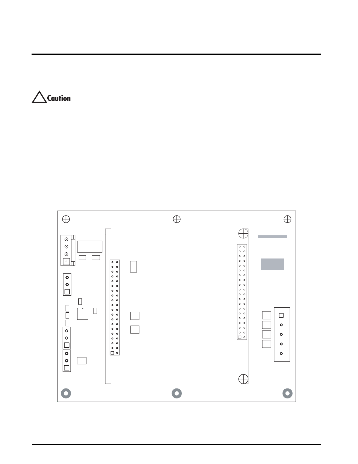
2.3 Cable Connections
The single channel iQube provides one load cell
connector, two remote display connectors, one host
(PC) com port connector for connecting to the PC
running
VIRTUi, and an AC power cord.
2.4 Load Cells
The load cell wired to connector J3 in the iQube, is
assigned a default name A1. J3 is wired to a DB-9 on
the enclosure panel.
.
DC IN
1
HOST SERIAL
1
REMOTE
1
REMOTE
1
J7
J5
C2
C3
C5
GNDTxDDC+TxD
DC+GND
RxD
TxDGND
J4
J6
G2E
R1
F1
J2
R2
D1
C4
C1
U1
C6
TVS5
TVS6
J1
RICE LAKE
Assembly
P/N
TVS4
TVS3
TVS2
TVS1
Rev.
1
+SIG
–SIG +EXC
–EXC
SHLD
J3
Figure 2-1. iQube Connector Board with Core Module
2 Trac er AVi Installation Manual
Page 7

Load Cell Wiring
To attach the load cell cable to the connector board,
plug the cable into external connector (see
Figure 2-6
on page 6).
Wire load cell cables as shown in Table 2-1.
Given that these and other factors will affect the
maximum usable cable length, the following distances
can be used as a general guide for
iQube
communications cabling (10 ft cable is provided):
RS-232: 50 ft (15 m)
On-Board
DB-9 Pin
Female Connector
7 1 +SIG
3 2 –SIG
4 3 +EXC
6 4 –EXC
5 5 SHIELD
Table 2-1. Load Cell Connector Pin Assignments
Connector
(J3) Function
2.5 Serial Communications
The J4, J6 and J7 serial communications ports on the
iQube connector board support communications
between the
remote display.)
• Port J4 supports full-duplex RS-232
To attach serial communications cables, plug cable
into the external DB-9 connectors labeled Remote
Display.
Table 2-2 shows the pin assignments for connectors
J4, J6, and J7.
Connector DB-9 Pin Pin Signal
J4
(Host Com)
J6
(Remote)
J7
(Remote)
iQube and a host device (PC and/or
communications between the
iQube unit and a
host device.
Port J6 and J7 are used to connect to the
remote display(s).
Male 2 1 TxD
Male 3 2 RxD
Male 5 3 Gnd
Female 1 1 DC+
Female 2 2 GnD
Female 9 3 TxD
Female 1 1 DC+
Female 2 2 GnD
Female 9 3 TxD
2.6 Core Module DIP Switches
The DIP switches on the iQube core module must be
set to configure the
iQube as a primary or secondary
unit, and to specify the type of serial communications
provided by the unit.
Table 2-3 lists the DIP switches
and their functions.
Switch Function Values
1–3 Primary OFF, OFF, OFF = PRIMARY
4 Setup enable ON = setup enabled
5 Host
communication
protocol
6 Host
communication
port
7 Reserved OFF
8 Load default OFF
Table 2-3. Core Module DIP Switch Settings
OFF = RS-232
OFF = Port J7
2.7 Core Module Reset Procedure
If VIRTUi does not recognize the connection to the
load cell, the core module may need to be reset to
initialize the
To reload the default firmware into the iQube core
module, do the following:
1. Power-off the iQube. Remotely powered units
2. Set core module DIP switch 8 ON.
3. Power-on the iQube.
4. Power-off the iQube.
5. Set DIP switch 8 OFF.
6. Power-on the iQube. The reset is now complete.
iQube firmware.
can be powered off by temporarily removing
fuse F1 (see
Figure 2-1 on page 2).
Table 2-2. Serial Port Pin Assignments
Communications Cable Distance Limitations
The maximum cable lengths that can be used for
various communications types depend on a number of
factors. These include: output impedance of the
transmitter; electrical noise in the environment; cable
capacitance, gauge, termination, and shielding.
Installation 3
Page 8

2.8 The Power Supply
The internal power supply provides 7.5VDC power
for the
iQube from 115 or 230 VAC power sources.
Figure 2-2. iQube 7.5V Power Supply
2.11 Replacement Parts and Drawings
Table 2-5 lists replacement parts for the Trac er AVi.
2.9 Fuse Replacement
Fuse F1 on the iQube connector board (see Figure 2-1
on page 2) provides protection for power supplied to
the connector board and core module at connector J5.
Fuse F1 is poly resettable and does not need
replacement. See
Section 6.0 on page 17 for complete
fuse specifications.
2.10 Interface Cables
Table 2-4 lists the cables for the iQube.
PN Description
50749 Cable for com port to PC
72704 RS-232/USB connector
93563 Cable for remote display
Table 2-4. iQube Cables
PN Description (Quantity)
93550
93552 Connector board (1)
93553
76556 Power supply (1)
93213 Remote display enclosure, front (1)
93214 Remote display, back (1)
93561 Remote display CPU board (1)
93215 Display lens (1)
93633 Installation manual (1)
iQube enclosure (1)
iQube core module (1)
Table 2-5. Replacement Parts
4 Trac er AVi Installation Manual
Page 9

NETWORK
PC
running
VIRTUi
USB
A
C
P
O
W
E
R
RS-232 to USB
CONVERTER CABLE
PORT
iQUBE
Remote Display Remote Display #2
CAPACITY 500 x 0.5lb/250 x 0.2kg CLASS III n
lb
kg
1000
max.
Gr
Nt
CAPACITY 500 x 0.5lb/250 x 0.2kg CLASS III n
Gr
lb
kg
1000
max.
Nt
Benchmark HD Scale Base
LOAD CELL CABLE
Figure 2-3. System Configuration
Figure 2-4. Remote Display Cutout
Installation 5
Page 10

Figure 2-5. Remote Display Drawing
85-265 VAC,
50-60Hz,
2A
6 Trac er AVi Installation Manual
Remote Display
Remote Display
Com Port
Figure 2-6. iQube Cable Connections
Load Cell
Page 11

3.0 PC Configuration
The iQubeTM can be configured using a PC running VIRTUi.
3.1 Introduction to VIRTUi
VIRTUi is a PC-based virtual indicator designed to replicate the form and function of a single function indicator.
The virtual front panel consists of a display and five-button keypad. Keys are activated by a mouse click.
Features included:
• Electronic data processing (EDP) port for
full-duplex, RS-232 communications up to
57600 bps
• Printer port for output-only, RS-232
communications up to 57600 bps
Figure 3-1. VIRTUi Main Screen
VIRTUi is NTEP-Certified for Classes III and III L at
10,000 divisions
NOTES:
To send and receive commands from VIRTUi using
HyperTerminal:
1. Open HyperTerminal on the PC
2. Connect to “localhost” on port 20355 using
TCP/IP
By default, VIRTUi is always the top window within
®
Windows
. This is required by NTEP to ensure the
weight is visible at all times. This can be changed in
the Application Settings if Legal-for-Trade
requirements are
not necessary.
Auto-Update Feature
If connected to the Internet, VIRTUi’s Auto-update
feature will automatically download updates to the
program. The auto-update feature will only function if
the user is logged in to Windows as “Administrator”
and/or if the user has “write” access to the application
installation directory.
PC Configuration 7
Page 12

3.1.1 Authentication/Authorization System
The User Manager is a security feature of VIRTUi and
is used to set up
VIRTUi users, their “roles” and the
permissions for those roles. The User Manager for
authentication/authorization can be found under the
File menu. After installing
VIRTUi, the user must
logon as “Administrator” to access the User Manager.
Figure 3-3. Username and Password
Figure 3-2. Logon
Certain VIRTUi functions can be disabled for particular users, or roles. Only the Administrator can configure the
User Manager.
8 Trac er AVi Installation Manual
Figure 3-4. User Manager
Page 13

To add a new user, a user name and password must be configured.
Figure 3-5. Add User
Using the Permissions Manager, resources and allowed roles can be configured for each role.
Figure 3-6. Permissions Manager
PC Configuration 9
Page 14

3.1.2 Communication
The steps in this section summarize how to configure VIRTUi to communicate with the iQube and a remote
display.
1. With the PC and iQube connected and the
VIRTUi program running, select
Communications Settings from the Settings menu.
2. Select iQube Port in the left section of the
4. Select Stream format in the left section of the
screen under the Communications folder
5. Select Rice Lake Extended from the drop-down
box and click
Save.
screen under the Communications folder.
3. Mark the Streaming Port checkbox, shown in
Figure 3-7, and click Save.
Figure 3-8. Stream Format
Figure 3-7. iQube Port
3.1.3 Function Keys and Annunciators
Function keys and annunciators are summarized in this section.
Function Keys
The function keys below perform the front panel functions via the computer keyboard:
Key F5 F6 F7 F8 F9
Function Zero Gross/Net Ta re Units Print
Table 3-1. Function Keys
Annunciators
The VIRTUi display uses a set of eight annunciators to provide additional information about the value being
displayed:
• Gross and Net annunciators are lit to show whether the display weight is a gross or net weight
• Center of Zero: Gross weight is within 0.25 graduations of zero. This annunciator lights when the scale is
zeroed
• Standstill: Scale is at standstill or within the specified motion band. Some operations, including tare
functions and printing, can only be done when the standstill symbol is shown
• The display units can also be set to short tons (tn), metric tons (t), or NONE (no units information
displayed). The lb and kg annunciators default as primary and secondary unit annunciators. Changing
unit annunciators under the Settings menu will also change the annunciators on the
3.1.4 VIRTUi Operations
VIRTUi display.
This section summarizes the basic operations of VIRTUi.
Toggle Gross/Net Mode
Press the Gross/Net key to switch the display mode between Gross and Net. If a tare value has been entered or
acquired, the net value is the gross weight minus the tare. Gross mode is shown by the Gross annunciator; Net
mode is shown by the Net annunciator.
10 Tracer AVi Installation Manual
Page 15

Zero Scale
1. In gross mode, remove all weight from the
scale and wait for the standstill annunciator.
2. Press the Zero key. The Center of Zero
annunciator lights to indicate the scale is
zeroed.
Remove Stored Tare Value
1. Remove all weight from the scale and wait for
the standstill annunciator.
2. Press the T ARE key. The indicator switches to
gross mode, indicating the tare value has been
removed.
Acquire Tare
1. Place container on scale and wait for standstill
annunciator.
2. Press the TARE key to acquire the tare weight
Print Ticket
1. Wait for standstill annunciator.
2. Press the Print key to send data to the serial
port.
of the container. The indicator switches to net
mode.
3.1.5 Web Browser-Based Cell Status
iQube load cell status can be reported via a standard web browser . A “http://localhost:5050” URL is used to view
the status page. “Http” must be included as it is not inferred, and “localhost” can be replaced with the appropriate
IP address or domain name.
Figure 3-9. Cell Status
3.1.6 System Requirements
Minimum
• Windows 98 or greater
• I nternet Explorer 5.5 or greater
• .NET Framework 1.1
•64 MB RAM
• 30 MB free hard drive space
• Serial port connection for connection to
iQube
Additional serial ports are required for connection to
printers/remote displays.
Recommended
• Windows 2000 or greater
• I nternet Explorer 6.0 SP1
• . Net Framework 1.1
•128 MB RAM
• 30 MB free hard drive space
• Serial port for connection to iQube
Additional serial ports are required for connection to
printers/remote displays.
PC Configuration 11
Page 16

3.2 VIRTUI Configuration
VIRTUi can be used to set iQube configuration parameters. When configuration is complete, data is downloaded
iQube.
to the
To configure the iQube using VIRTUi:
1. With the PC and iQube connected and the VIRTUi program running, select iQube Configuration from the
Settings menu.
Figure 3-10. VIRTUi Tracer AVi Display
2. Select the Cells display. Use this display to select the load cell used in the Tracer AVi system by checking
the box to the left of the cell. Enter load cell data such as factory sensitivity, serial number, and capacity
on the General Information sheet for the cell.
3. Select the Platforms display. The cell that was checked on the Cells screen is now listed as Available
Load Cell for the iQube.
4. Click on Platform 1.
5. Double-click on the load cell to move the cell into the Assigned Load Cell column for Platform 1.
As the cell is added to the Assigned Cell column, a Section Format Diagram is displayed at the bottom of
the screen.
6. Select the Systems display.
7. Click on System 1.
8. Platform 1 is now shown in the Assigned Platforms field. Click the Platform 1 box to assign Platform 1 to
System 1. Use the General display to enter scale system parameters.
3.2.1 Downloading to the Tracer AVi
Once configuration is complete, you must download the configuration data from the PC to the iQube.
1. Select Send Configuration to write the values to the iQube.
2. Click Begin to initiate the download. Downloading may take up to 30 seconds.
12 Tracer AVi Installation Manual
Page 17

4.0 Calibration
VIRTUi Calibration
With the iQube connected to a PC running the VIRTUi program, do the following:
1. From the Settings menu, select Calibration then Multi-Point.
Figure 4-1. Platform Selection
2. Remove all weight from the scale platform. Click on Calibrate. The word Tr an sm it ti ng is displayed while
the zero value is calculated. This process can last up to 45 seconds.
Figure 4-2. Calibration
3. Enter the test weight value in the Calibration Weight field. You are now ready to measure the load cell
output using the Multi-Point procedure.
Calibration 13
Page 18

4. Place the test weight over the cell to be measured.
Figure 4-3. Multi-Point Calibration
5. Click the first Measure box.
Figure 4-4. Step Complete
14 Tracer AVi Installation Manual
Page 19

6. Click Finish. Multi-Point automatically calculates the load cell trim factor.
Figure 4-5. Calibration Complete
7. Click Exit.
iQube calibration is complete. You can view the active status of the cell, platform, or system by returning to the
Tools menu and selecting Cell Diagnostic Monitor. Click on the Auto Refresh box to automatically update the readings
from the
iQube.
Calibration 15
Page 20

5.0 Diagnostics
5.1 Diagnostic Tests
The iQube provides a number of diagnostic tests, including boundary, weighing, and system tests.
5.2 Diagnostic Setup
Parameters associated with each of the iQube’s diagnostic tests can be set using VIRTUi.
Figure 5-1. VIRTUi Diagnostic Setup Display
16 Tracer AVi Installation Manual
Page 21

6.0 Specifications
Power
Power Consumption (+7.5 VDC)
1-channel, 350Ω load cell 75 mA (0.563 W)
Fuse 2A TR5 subminiature fuse
Wickmann Time-Lag 19374 Series
UL Listed, CSA Certified and Approved
A/D Specifications
Excitation Voltage 4 VDC (+4V and ground, single-sided)
Analog Signal Input Range –11.7 mV to +27.3 mV
A/D Sample Rate 15 Hz
Serial Communications
J4 Port Full duplex RS-232
J6 Port Simplex RS-232
J7 Port Simplex RS-232
Environmental
Operating Temperature–10 to +40 C (14 to 104 F)
Storage Temperature –10 to +70 C (14 to 158 F)
Humidity 0–95% relative humidity
Enclosure
Enclosure Dimensions 8.00 in x 6.00 in x 3.5 in
20 cm x 15 cm x 9 cm
Weight 1.0 lb (.453 Kg)
Certifications and Approvals
O
C
N
NTEP
F
L
E
A
R
N
E
O
I
N
T
C
A
E
N
•
•
O
N
W
E
I
G
H
T
CoC Number 03-032
S
E
R
U
S
A
Accuracy Class III/IIIL n
E
S
M
A
D
N
: 10 00000
max
Specifications 17
Page 22

Tracer AVi Limited Warranty
Rice Lake Weighing Systems (RLWS) warrants that all RLWS equipment and systems properly installed by a
Distributor or Original Equipment Manufacturer (OEM) will operate per written specifications as confirmed by
the Distributor/OEM and accepted by RLWS. All systems and components are warranted against defects in
materials and workmanship for two years.
RLWS warrants that the equipment sold hereunder will conform to the current written specifications authorized
by RLWS. RLWS warrants the equipment against faulty workmanship and defective materials. If any equipment
fails to conform to these warranties, RLWS will, at its option, repair or replace such goods returned within the
warranty period subject to the following conditions:
• Upon discovery by Buyer of such nonconformity, RLWS will be given prompt written notice with a
detailed explanation of the alleged deficiencies.
• Individual electronic components returned to RLWS for warranty purposes must be packaged to
prevent electrostatic discharge (ESD) damage in shipment. Packaging requirements are listed in a
publication, Protecting Your Components From Static Damage in Shipment, available from RLWS
Equipment Return Department.
• Examination of such equipment by RLWS confirms that the nonconformity actually exists, and was
not caused by accident, misuse, neglect, alteration, improper installation, improper repair or
improper testing; RLWS shall be the sole judge of all alleged non-conformities.
• S uch equipment has not been modified, altered, or changed by any person other than RLWS or its
duly authorized repair agents.
• RLWS will have a reasonable time to repair or replace the defective equipment. Buyer is responsible
for shipping charges both ways.
• In no event will RLWS be responsible for travel time or on-location repairs, including assembly or
disassembly of equipment, nor will RLWS be liable for the cost of any repairs made by others.
THESE WARRANTIES EXCLUDE ALL OTHER WARRANTIES, EXPRESSED OR IMPLIED, INCLUDING WITHOUT
LIMITATION WARRANTIES OF MERCHANTABILITY OR FITNESS FOR A PARTICULAR PURPOSE. NEITHER
RLWS
NOR DISTRIBUTOR WILL, IN ANY EVENT, BE LIABLE FOR INCIDENTAL OR CONSEQUENTIAL DAMAGES.
RLWS AND BUYER AGREE THAT RLWS’ SOLE AND EXCLUSIVE LIABILITY H EREUNDER IS LIMITED TO
REPAIR OR REPLACEMENT OF SUCH GOODS. IN ACCEPTING THIS WARRANTY, THE BUYER WAIVES ANY AND
ALL OTHER CLAIMS TO WARRANTY.
SHOULD THE SELLER BE OTHER THAN RLWS, THE BUYER AGREES TO LOOK ONLY TO THE SELLER FOR
WARRANTY CLAIMS.
NO TERMS, CONDITIONS, UNDERSTANDING, OR AGREEMENTS PURPORTING TO MODIFY THE TERMS OF THIS
WARRANTY SHALL HAVE ANY LEGAL EFFECT UNLESS MADE IN WRITING AND SIGNED BY A CORPORATE
OFFICER OF RLWS AND THE BUYER.
© 2007 Rice Lake Weighing Systems, Inc. Rice Lake, WI USA. All Rights Reserved.
RICE LAKE WEIGHING SYSTEMS • 230 WEST COLEMAN STREET • RICE LAKE, WISCONSIN 54868 • USA
18 Tracer AVi Installation Manual
 Loading...