

Page 1
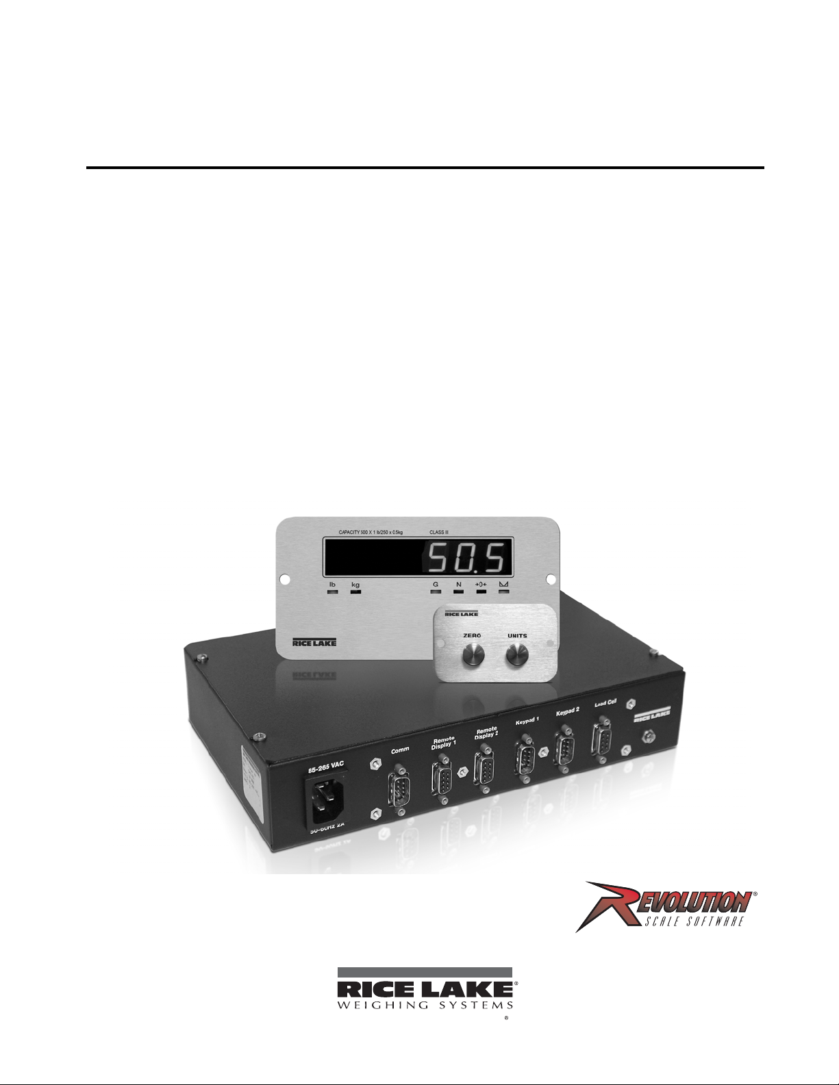
Tracer AV
To be the best by ever y measure
Aviation Baggage Instrumentation
Installation Manual
98316
Page 2

Page 3

Technical training seminars are available through Rice Lake Weighing Systems.
Course descriptions and dates can be viewed at www.ricelake.com/training
or obtained by calling 715-234-9171 and asking for the training department.
Contents
About This Manual ................................................................................................................................... 1
1.0 Introduction.................................................................................................................................. 1
1.1 Operating Modes . . . . . . . . . . . . . . . . . . . . . . . . . . . . . . . . . . . . . . . . . . . . . . . . . . . . . . . . . . . . . . . . 1
1.2 Display and Keypad . . . . . . . . . . . . . . . . . . . . . . . . . . . . . . . . . . . . . . . . . . . . . . . . . . . . . . . . . . . . . . 2
1.3 LED Annunciators. . . . . . . . . . . . . . . . . . . . . . . . . . . . . . . . . . . . . . . . . . . . . . . . . . . . . . . . . . . . . . . . 2
1.4 Tracer AV Operations . . . . . . . . . . . . . . . . . . . . . . . . . . . . . . . . . . . . . . . . . . . . . . . . . . . . . . . . . . . . . 2
1.4.1 Toggle Units . . . . . . . . . . . . . . . . . . . . . . . . . . . . . . . . . . . . . . . . . . . . . . . . . . . . . . . . . . . . . . . . . . . . . 2
1.4.2 Zero Scale. . . . . . . . . . . . . . . . . . . . . . . . . . . . . . . . . . . . . . . . . . . . . . . . . . . . . . . . . . . . . . . . . . . . . . . 2
2.0 Installation ................................................................................................................................... 3
2.1 Unpacking and Assembly. . . . . . . . . . . . . . . . . . . . . . . . . . . . . . . . . . . . . . . . . . . . . . . . . . . . . . . . . . 3
2.2 Enclosure Security/Disassembly. . . . . . . . . . . . . . . . . . . . . . . . . . . . . . . . . . . . . . . . . . . . . . . . . . . . . 3
2.3 Cable Connections. . . . . . . . . . . . . . . . . . . . . . . . . . . . . . . . . . . . . . . . . . . . . . . . . . . . . . . . . . . . . . . 4
2.3.1 Illustrations . . . . . . . . . . . . . . . . . . . . . . . . . . . . . . . . . . . . . . . . . . . . . . . . . . . . . . . . . . . . . . . . . . . . . . 5
2.3.2 Load Cells. . . . . . . . . . . . . . . . . . . . . . . . . . . . . . . . . . . . . . . . . . . . . . . . . . . . . . . . . . . . . . . . . . . . . . . 7
2.3.3 Serial Communications . . . . . . . . . . . . . . . . . . . . . . . . . . . . . . . . . . . . . . . . . . . . . . . . . . . . . . . . . . . . . 7
2.3.4 Digital I/O . . . . . . . . . . . . . . . . . . . . . . . . . . . . . . . . . . . . . . . . . . . . . . . . . . . . . . . . . . . . . . . . . . . . . . . 8
2.4 Board Removal . . . . . . . . . . . . . . . . . . . . . . . . . . . . . . . . . . . . . . . . . . . . . . . . . . . . . . . . . . . . . . . . . 9
2.5 Replacement Parts. . . . . . . . . . . . . . . . . . . . . . . . . . . . . . . . . . . . . . . . . . . . . . . . . . . . . . . . . . . . . . . 9
3.0 Configuration ............................................................................................................................. 10
3.1 Configuration Methods. . . . . . . . . . . . . . . . . . . . . . . . . . . . . . . . . . . . . . . . . . . . . . . . . . . . . . . . . . . 10
3.1.1 Revolution Configuration . . . . . . . . . . . . . . . . . . . . . . . . . . . . . . . . . . . . . . . . . . . . . . . . . . . . . . . . . . . 10
3.1.2 EDP Command Configuration . . . . . . . . . . . . . . . . . . . . . . . . . . . . . . . . . . . . . . . . . . . . . . . . . . . . . . . 10
3.1.3 Front Panel Configuration . . . . . . . . . . . . . . . . . . . . . . . . . . . . . . . . . . . . . . . . . . . . . . . . . . . . . . . . . . 11
3.1.4 Setting Numeric Values For Parameters . . . . . . . . . . . . . . . . . . . . . . . . . . . . . . . . . . . . . . . . . . . . . . . 11
3.1.5 Editing Integers . . . . . . . . . . . . . . . . . . . . . . . . . . . . . . . . . . . . . . . . . . . . . . . . . . . . . . . . . . . . . . . . . . 12
3.1.6 Editing Floating Point (Decimal Point Position) . . . . . . . . . . . . . . . . . . . . . . . . . . . . . . . . . . . . . . . . . . . 12
3.2 Menu Structures and Parameter Descriptions. . . . . . . . . . . . . . . . . . . . . . . . . . . . . . . . . . . . . . . . . .12
3.2.1 Default Calibration Menu . . . . . . . . . . . . . . . . . . . . . . . . . . . . . . . . . . . . . . . . . . . . . . . . . . . . . . . . . . . 12
3.2.2 Configuration Menu. . . . . . . . . . . . . . . . . . . . . . . . . . . . . . . . . . . . . . . . . . . . . . . . . . . . . . . . . . . . . . . 13
3.2.3 Format Menu. . . . . . . . . . . . . . . . . . . . . . . . . . . . . . . . . . . . . . . . . . . . . . . . . . . . . . . . . . . . . . . . . . . . 15
3.2.4 Calibration Menu. . . . . . . . . . . . . . . . . . . . . . . . . . . . . . . . . . . . . . . . . . . . . . . . . . . . . . . . . . . . . . . . . 17
3.2.5 Serial Menu . . . . . . . . . . . . . . . . . . . . . . . . . . . . . . . . . . . . . . . . . . . . . . . . . . . . . . . . . . . . . . . . . . . . . 17
3.2.6 Program Menu . . . . . . . . . . . . . . . . . . . . . . . . . . . . . . . . . . . . . . . . . . . . . . . . . . . . . . . . . . . . . . . . . . 19
3.2.7 Setpoint Menu. . . . . . . . . . . . . . . . . . . . . . . . . . . . . . . . . . . . . . . . . . . . . . . . . . . . . . . . . . . . . . . . . . . 21
3.2.8 Version Menu . . . . . . . . . . . . . . . . . . . . . . . . . . . . . . . . . . . . . . . . . . . . . . . . . . . . . . . . . . . . . . . . . . . 22
4.0 Calibration ................................................................................................................................. 23
4.1 Default Calibration . . . . . . . . . . . . . . . . . . . . . . . . . . . . . . . . . . . . . . . . . . . . . . . . . . . . . . . . . . . . . . 23
4.2 Standard Calibration. . . . . . . . . . . . . . . . . . . . . . . . . . . . . . . . . . . . . . . . . . . . . . . . . . . . . . . . . . . . . 24
4.3 EDP Command Calibration. . . . . . . . . . . . . . . . . . . . . . . . . . . . . . . . . . . . . . . . . . . . . . . . . . . . . . . . 24
4.4 Revolution® Calibration . . . . . . . . . . . . . . . . . . . . . . . . . . . . . . . . . . . . . . . . . . . . . . . . . . . . . . . . . . 25
4.5 More About Calibration. . . . . . . . . . . . . . . . . . . . . . . . . . . . . . . . . . . . . . . . . . . . . . . . . . . . . . . . . . . 25
4.5.1 Adjusting Final Calibration . . . . . . . . . . . . . . . . . . . . . . . . . . . . . . . . . . . . . . . . . . . . . . . . . . . . . . . . . . 25
4.5.2 A/D Counts . . . . . . . . . . . . . . . . . . . . . . . . . . . . . . . . . . . . . . . . . . . . . . . . . . . . . . . . . . . . . . . . . . . . . 25
© 2011 Rice Lake Weighing Systems. All rights reserved. Printed in the United States of America.
Specifications subject to change without notice.
Rice Lake Weighing Systems is an ISO 9001 registered company.
February 2011
i
Page 4

Rice Lake continually offers web-based video training on a growing selection
of product-related topics at no cost. Visit www.ricelake.com/webinars.
5.0 EDP Commands.......................................................................................................................... 26
5.1 The EDP Command Set . . . . . . . . . . . . . . . . . . . . . . . . . . . . . . . . . . . . . . . . . . . . . . . . . . . . . . . . . 26
5.1.1 Key Press Commands . . . . . . . . . . . . . . . . . . . . . . . . . . . . . . . . . . . . . . . . . . . . . . . . . . . . . . . . . . . . 26
5.1.2 Reporting Commands. . . . . . . . . . . . . . . . . . . . . . . . . . . . . . . . . . . . . . . . . . . . . . . . . . . . . . . . . . . . . 27
5.1.3 The RESETCONFIGURATION Command . . . . . . . . . . . . . . . . . . . . . . . . . . . . . . . . . . . . . . . . . . . . . . 27
5.1.4 Parameter Setting Commands . . . . . . . . . . . . . . . . . . . . . . . . . . . . . . . . . . . . . . . . . . . . . . . . . . . . . . 27
5.1.5 Soft Reset. . . . . . . . . . . . . . . . . . . . . . . . . . . . . . . . . . . . . . . . . . . . . . . . . . . . . . . . . . . . . . . . . . . . . . 27
5.1.6 Normal Mode Commands. . . . . . . . . . . . . . . . . . . . . . . . . . . . . . . . . . . . . . . . . . . . . . . . . . . . . . . . . . 30
5.2 Saving and Transferring Data. . . . . . . . . . . . . . . . . . . . . . . . . . . . . . . . . . . . . . . . . . . . . . . . . . . . . . 31
5.2.1 Saving Tra cer AV Data to a Personal Computer. . . . . . . . . . . . . . . . . . . . . . . . . . . . . . . . . . . . . . . . . 31
5.2.2 Downloading Configuration Data from PC to
Tra cer AV . . . . . . . . . . . . . . . . . . . . . . . . . . . . . . . . . . . 31
6.0 Appendix .................................................................................................................................... 32
6.1 Error Messages . . . . . . . . . . . . . . . . . . . . . . . . . . . . . . . . . . . . . . . . . . . . . . . . . . . . . . . . . . . . . . . . 32
6.1.1 Displayed Error Messages . . . . . . . . . . . . . . . . . . . . . . . . . . . . . . . . . . . . . . . . . . . . . . . . . . . . . . . . . 32
6.1.2 Using the XE EDP Command . . . . . . . . . . . . . . . . . . . . . . . . . . . . . . . . . . . . . . . . . . . . . . . . . . . . . . . 33
6.2 Status Messages . . . . . . . . . . . . . . . . . . . . . . . . . . . . . . . . . . . . . . . . . . . . . . . . . . . . . . . . . . . . . . . 33
6.2.1 Using the P EDP Command . . . . . . . . . . . . . . . . . . . . . . . . . . . . . . . . . . . . . . . . . . . . . . . . . . . . . . . . 33
6.2.2 Using the ZZ EDP Command . . . . . . . . . . . . . . . . . . . . . . . . . . . . . . . . . . . . . . . . . . . . . . . . . . . . . . . 33
6.3 Continuous Output (Stream) Format . . . . . . . . . . . . . . . . . . . . . . . . . . . . . . . . . . . . . . . . . . . . . . . . 34
6.4 Front Panel Display Characters . . . . . . . . . . . . . . . . . . . . . . . . . . . . . . . . . . . . . . . . . . . . . . . . . . . . 35
6.5 Conversion Factors for Secondary Units . . . . . . . . . . . . . . . . . . . . . . . . . . . . . . . . . . . . . . . . . . . . . 36
6.6 Digital Filtering . . . . . . . . . . . . . . . . . . . . . . . . . . . . . . . . . . . . . . . . . . . . . . . . . . . . . . . . . . . . . . . . . 37
6.6.1 DIGFLx Parameters. . . . . . . . . . . . . . . . . . . . . . . . . . . . . . . . . . . . . . . . . . . . . . . . . . . . . . . . . . . . . . . 37
6.6.2 DFSENS and DFTHRH Parameters. . . . . . . . . . . . . . . . . . . . . . . . . . . . . . . . . . . . . . . . . . . . . . . . . . . 37
6.6.3 Setting the Digital Filter Parameters. . . . . . . . . . . . . . . . . . . . . . . . . . . . . . . . . . . . . . . . . . . . . . . . . . . 38
6.7 Test Mode . . . . . . . . . . . . . . . . . . . . . . . . . . . . . . . . . . . . . . . . . . . . . . . . . . . . . . . . . . . . . . . . . . . . 39
6.8 Regulatory Mode Functions. . . . . . . . . . . . . . . . . . . . . . . . . . . . . . . . . . . . . . . . . . . . . . . . . . . . . . . 40
6.9 LED Functions . . . . . . . . . . . . . . . . . . . . . . . . . . . . . . . . . . . . . . . . . . . . . . . . . . . . . . . . . . . . . . . . . 40
6.10 Specifications. . . . . . . . . . . . . . . . . . . . . . . . . . . . . . . . . . . . . . . . . . . . . . . . . . . . . . . . . . . . . . . . . 41
Tracer AV Limited Warranty................................................................................................................... 42
ii Tra ce r AV Installation Manual
Page 5

About This Manual
W arning
This manual is intended for use by service technicians
responsible for installing and servicing
Tra ce r AV
aviation baggage instrumentation. This manual
applies to units using Version 1.14 of the
Tracer AV
software.
Configuration and calibration of the
Tra ce r AV can be
accomplished using the 2-button keypad, the EDP
command set, or the
Revolution
®
configuration utility.
See Section 3.1 on page 10 for information about
configuration methods.
1.0 Introduction
The Tracer AV is a single-channel digital weight
indicator comprised of three components:
•The
• The RD-1 remote display (See Figure 1-1 2)
• The RK-1 keypad (See Figure 1-1 2) has two
Tra cer AV features include:
The
• Four-wire load cell connections; remote sense
• The electronic data processing (EDP) port is
• The serial port connects to the RD-1 remote
• Print formatting is defaulted for RD-1
• Digital inputs are defaulted for RK-1
• Setpoints values will cause the display to
• Available for 115 VAC and 230 VAC.
Tra cer AV houses the AC power supply
and CPU board. There are external DB-9
connectors for a PC connection, two remote
display connections, two remote keypad
connections, and a load cell connection (See
Figure 2-3 4).
is a large .8 in., six-digit, seven-segment LED
display. There are connectors for two remote
displays.
keys which are used to zero the scale and to
toggle between a primary and secondary unit
of measure in the normal mode of operation.
These keys have a secondary function for the
setup mode.
connections are not provided.
full duplex; RS-232 communications at up to
38400 bps. The EDP port is accessed through
the COMM connection.
displays. The output is RS-232 and will drive
two RD-1 units.
communications.
functionality.
flash when a specified weight value is
exceeded.
Some procedures described in this
manual require work inside the
AV
enclosure. These procedures are
to be performed by qualified service
personnel only.
Authorized distributors and their employees
can view or download this manual from the
Rice Lake Weighing Systems distributor
www.ricelake.com.
site at
1.1 Operating Modes
The Tra cer AV has three modes of operation:
Normal (Primary) mode
Normal mode is the default mode of the Tra ce r AV .
The indicator displays gross or net weights as
required, using the LED annunciators described in
Section 1.3 on page 2 to indicate scale status and
the type of weight value displayed. Once
configuration is complete and a legal seal is
affixed, this is the primary mode in which the
Tra ce r AV can operate.
Setup mode
Most of the procedures described in this manual
require the Tra cer AV to be in setup mode,
including configuration and calibration.
To enter setup mode, remove the setup switch
access screw on the
Once the screw is removed, use a small
screwdriver or pen tip to press the setup switch.
The display changes to show the word
Test mode
Test mode provides a number of diagnostic
functions for the
mode is entered using the setup switch. See
Section 6.7 on page 39 for more information.
NOTE: Test mode is intended for factory use only.
Tra ce r AV (See Figure 2-3 4).
DEFCAL.
Tra ce r AV . Like setup mode, test
Tra cer
Tracer AV Installation Manual - Introduction 1
Page 6
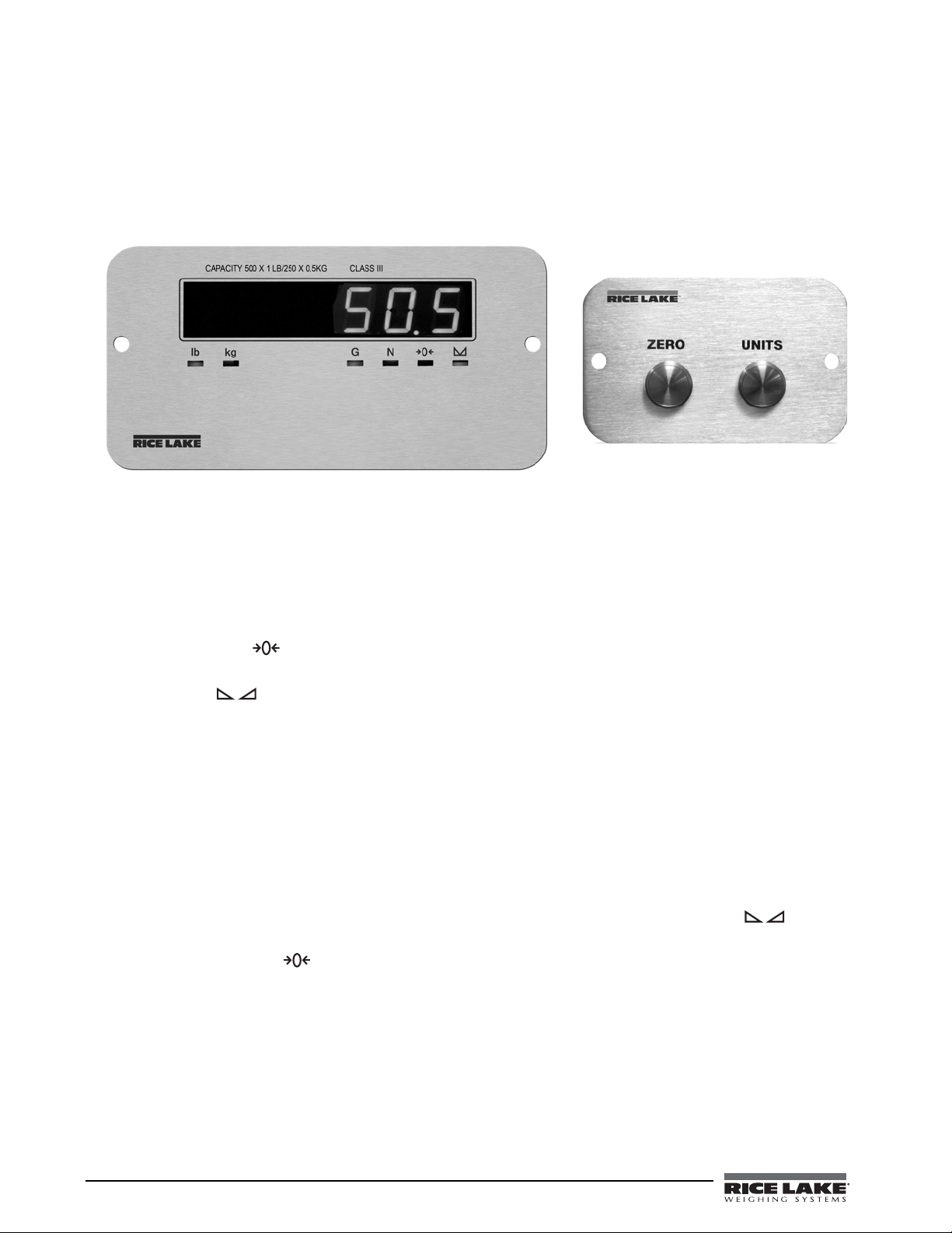
1.2 Display and Keypad
Figure 1-1 show s the Trac er AV LED display with annunciators and keypad. In setup mode, the keys are used to
navigate through menus, select digits within numeric values, and increment/decrement values. See Section 3.1.3
on page 11 for information about using the front panel k eys in setup mode.
.
Figure 1-1. RD-1 Front Panel, Showing LED Annunciators (left), and RK-1 2-Button Keypad (right)
1.3 LED Annunciators
The Tra ce r AV display uses a set of six LED annunciators to provide additional information about the value being
displayed:
•
Gross and Net annunciators are lit to show whether the displayed weight is a gross or net weight.
• Center of zero ( ): Gross weight is within 0.25 graduations of zero. This annunciator lights when the
scale is zeroed.
• Standstill ( ): Scale is at standstill or within the specified motion band. Some operations, including
tare functions and printing, can only be done when the standstill symbol is shown.
•
lb and kg annunciators indicate the units associated with the displayed value: lb=pounds, kg=kilograms.
1.4 Tracer AV Operations
Basic Tra cer AV operations are summarized be low.
1.4.1 Toggle Units
Press the Units key to switch between primary and secondary units. The appropriate units LED under the display
is lit.
1.4.2 Zero Scale
1. In gross mode, remove all weight from the scale and wait for the standstill annunciator ( ).
2. Press the
The center of zero ( ) annunciator lights to indicate the scale is zeroed.
Zero key.
2 Tracer AV Installation Manual
Page 7
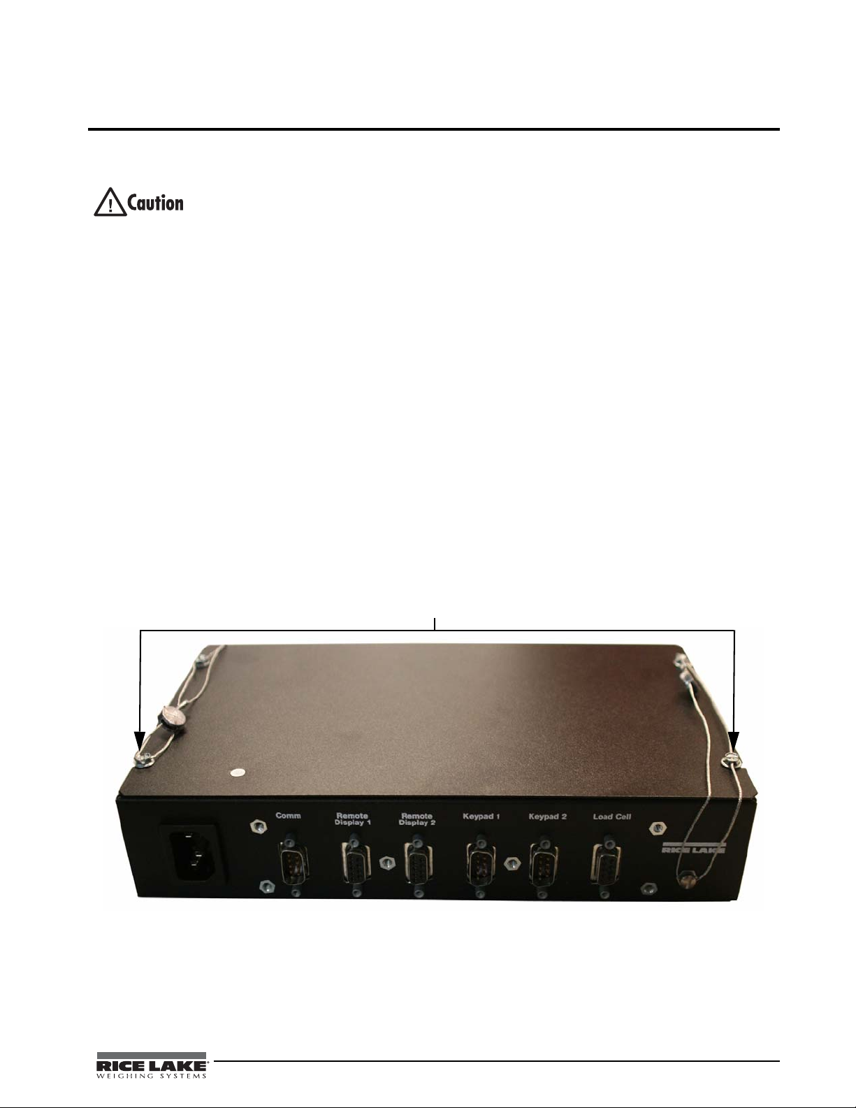
2.0 Installation
Security cables
This section describes the connections between the DB-9 plugs and the CPU board. This section also includes
assembly drawings, connection tables, and parts lists for the service technician.
• Use a wrist strap to ground yourself and protect components from electrostatic discharge (ESD) when
working inside the Tracer AV enclosure.
• This unit uses line fusing which could create an electric shock hazard. Procedures requiring work inside
Tra cer AV enclosure must be performed by qualified service personnel only.
the
• The supply cord serves as the main power disconnect for the Tracer AV. The power outlet must be
installed near the unit and be easily accessible.
2.1 Unpacking and Assembly
Immediately after unpacking, visually inspect the Tra ce r AV to ensure all components are included and
undamaged. The shipping carton should c ontain the
manual, two cables, and a power cord. If any parts were damaged in shipment, notify Rice Lake Weighing
Systems and the shipper immediately.
2.2 Enclosure Security/Disassembly
After an NTEP inspector has examined the unit, he/she will install security cables pictured in Figure 2-1 and
Figure 2-2. These cables prevent the
cables are removed, NTEP certification will become void.
If the
Tra cer AV enclosure must be ope ned by an a uthorized tech nic ian, ensure power is disc onne cted, then place
it on an anti-static work mat. Cut tamper-proof cables, remove screws, and remove the enclosure’s top cover. An
NTEP inspector will have to examine the unit and attach new security cables.
Tra ce r AV from being tampered with by an unauthorized individual. If these
Tra ce r AV enclosure, remote display, remote keypad, this
Figure 2-1. Trac er AV (front) security cables installed after NTEP certification.
Tracer AV Installation Manual - Installation 3
Page 8
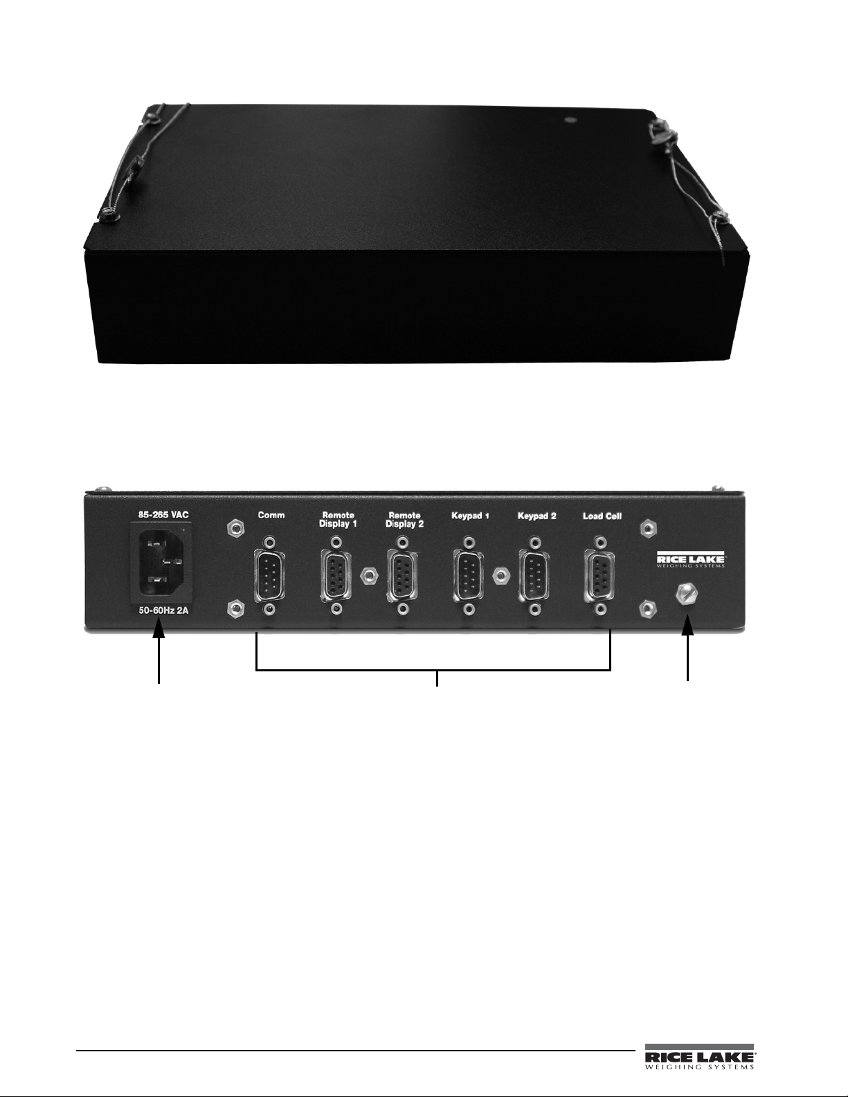
Figure 2-2. Trac er AV (back) security cables installed after NTEP certification.
Remove Screw to
Power Cord
Connection
Access Setup Switch
DB-9 Connections
2.3 Cable Connections
The Tracer AV provides several cable connections: one for the power cord, one to accommodate the load cell,
communications, remote displays, and keypads. Figure 2-3 shows the assignments for the
Details on pin assignments are shown in Table 2-1 through Table 2-5.
Figure 2-3. Trac er AV Power Cord Connection, DB-9 Connections, and Setup Switch Access Screw.
Tra ce r AV connections.
4 Tracer AV Installation Manual
Page 9
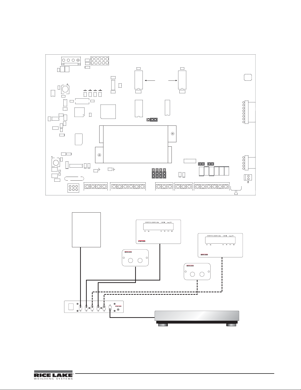
2.3.1 Illustrations
C7
RESET
R2
C15
C20
C19
R5
MECCA
C3
+5A V
R1
C13
R16
LED2
GND
GD1
C1
F1
DI 2
DI 1
DFB2
TR1
TVS2
TVS3
TVS6
C33
C31
DO2
DO1
C10
C9
+5V
G2E
R25
C30
VR3
R6
C8
U7
C5
C6
U8
R15
U1
LED1
EDP/
RS-232
JP2
C65
U3
SW1
SETUP
C32
C2
XT1
DFB1
TR2
TVS1
TVS5 TVS4
+3. 3
R7
R4
C16
C4
DIGIN
1
J1
LOAD CELL
U2
D1
U19
U6
U9
SERIAL
1
9
11
8
1
1
Gn d
20mA+
Gnd
TxD
Gnd
Gn d
DI 2
EXC-
E XC+
SEN-
SEN+
SIG-
5
1
1
1
20mA-
RxD
RxD
TxD
DI 1
SIG+
Micr opr ocesso r
DISPLA Y
DRIVERS
KEYPAD
CONNECTOR
REMOTE
SETUP
SWITCH
DC INPUT
R9
R10
R11
R12
ANA
ME M
AD
HB
J10
U4
OFF TEST
A/D CONVERTER
U10
U11
J2 J3 J4
J7
J8
J11
J12
JP1
DIGOUT
1
+5V
DO2
Gnd
DO1
J6
R46
R47
U14
JMP3
(Factory Only)
ON
OF F
KEYPAD
CONNECTOR
HE_J2
1
2
B1
+
85-265 VAC
50-60Hz 2A
Comm Remote
Display 1
Remote
Display 2
Keypad 1 Keypad 2 Load Cell
Revolution
Connection
Remote Display RD1/#1
Remote Keypad
Load Cell Cable
Tracer AV
Scale Base
Remote Display RD1/#2
ZERO UNITS
Remote Keypad
ZERO UNITS
The following illustrations show the Tra ce r AV CPU board, system configuration, remote display cutout, and
remote display drawing.
Figure 2-4. Tracer AV CPU Board
Figure 2-5. System Configuration
Tracer AV Installation Manual - Installation 5
Page 10
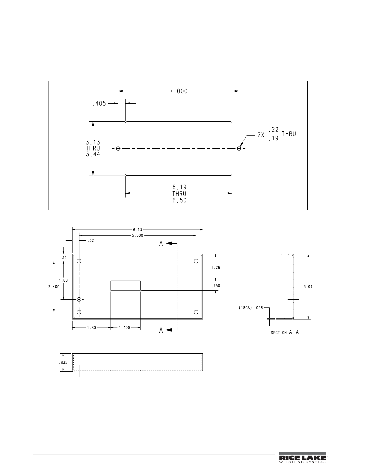
Figure 2-6. Remote Display Cutout
Figure 2-7. Remote Display Drawing
6 Tracer AV Installation Manual
Page 11
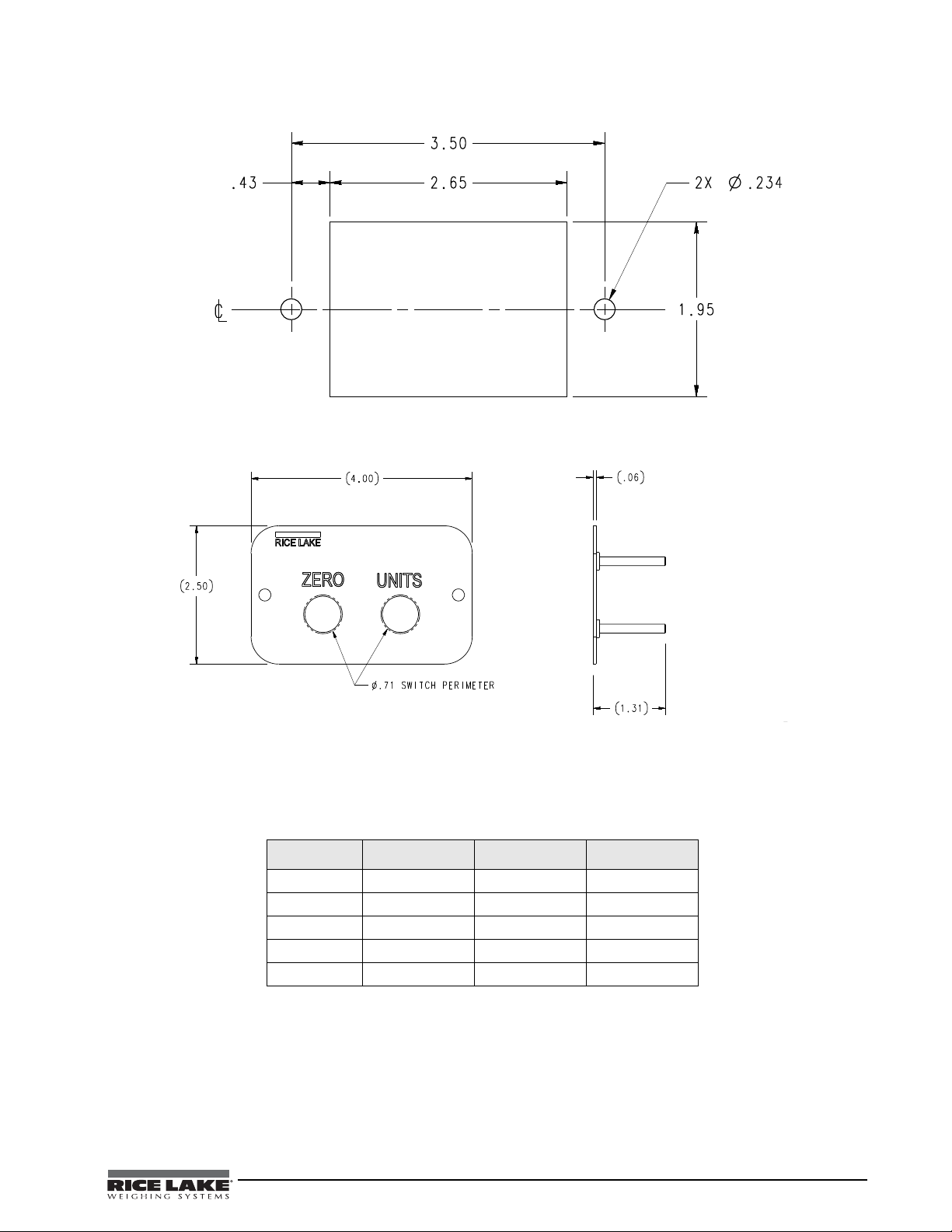
Figure 2-8. Switch Panel Cutout
Figure 2-9. Switch Panel Drawing
2.3.2 Load Cells
The load cell cable is connected to the socketed DB-9 marked load cell. This DB-9 is connected to the CPU
board on J1; see the table below for the pin assignments. The DB-9 is for four-wire installations, so leave sense
jumper JP1 and JP2 on.
DB-9 J1 Pins Function Pad Number
Pin 3 2 -Sig P 13
Pin 4 5 +Exc P 12
Pin 5 Shield
Pin 6 6 -Exc P 11
Pin 7 1 +Sig P 14
Table 2-1. J1 Load Cell
NOTE: The DB-9 is factory pinned for four-wire connections. Leave sense jumpers JP1 and JP2 on.
2.3.3 Serial Communications
The pinned DB-9 connector marked as COMM is connected to EDP port J3. It is bi-directional communication
to be used for a PC connection. Configuration using Revolution® software can be loaded through this connector.
Tracer AV Installation Manual - Installation 7
Page 12
There are two socketed DB-9 connectors for remote displays which are connected to the serial port J4. The
remote display’s DC power and communications are run in the same three-conductor cable. The serial port data
is transmitted on the 20 mA pins to the remote displays.
DB-9 EDP Port
COMM J3 Function Pad
Pin 2 1 EDP TxD P 1
Pin 3 2 EDP RxD P 2
Pin 5 3 EDP Gnd P 3
Table 2-2. EDP Port/COM
DB-9 Serial Port Digital Output
Remote J4 J6 Function Pad
n/a 4 +5 VDC P 4
n/a 4 20 mA+ P 5
n/a 5 20 mA- P 6
Pin 1 +7.5 VDC n/a
Pin 2 Gnd n/a
Pin 9 TxD n/a
Table 2-3. Serial Port/Remote Display
2.3.4 Digital I/O
Digital inputs can be set to provide several indicator functions, including all keypad functions. In the Trac er AV,
these inputs are set to
Zero and Units for the remote keypad. The inputs are active (on) with low voltage (0 VDC)
and can be driven by TTL or 5V logic without additional hardware. LEDs on the CPU board light when digital
inputs are active.
Digital Input
DB-9
Pin 4 1 Setup P 10
Pin 5 3 Gnd P 7
Pin 8 1 Dig In 1 P 9
Pin 9 2 Dig In 2 P 8
J2
J12 Function Pad Number
Table 2-4. Digital Input/Remote Keypad
Digital outputs are typically used to control relays that drive other equipment. In the
Tra ce r AV , the setpoint value
will cause the display to flash. Outputs are designed to sink not source, switching current. Each output is a
normally open connector circuit, capable of sinking 250 mA when active. Digital outputs are wired to switch
relays when the digital output is active (low, 0 VDC) with reference to 5 VDC supply. LEDs on the CPU board
light when the digital outputs are active.
Port Connector Pin Function
Digital
Output
8 Tracer AV Installation Manual
J6 1 Gnd
2DO 1
3DO 2
4+5V
Table 2-5. J6 Digital Outputs
Page 13
2.4 Board Removal
If you must remove the Tracer AV CPU board, use the following procedure:
• Use a wrist strap to ground yourself and protect components from electrostatic discharge (ESD) when
working inside the
Tra ce r AV enclosure.
• This unit uses line fusing which could create an electric shock hazard. Procedures requiring work inside
the
Tra cer AV enclosure must be performed by qualified service personnel only.
• The supply cord serves as the main power disconnect for the
Tra cer AV. The power outlet must be
installed near the unit and be easily accessible.
1. Disconnect power to the
Tra ce r AV .
2. Cut security cable (if installed) and remove screws.
3. Remove the top cover.
4. Disconnect power supply cable from connector J7 on the
Tra ce r AV CPU board.
5. Unplug connectors J1 (load cell cable), J2 (digital inputs), J3 (EDP), J4 (serial), J6 (digital outputs), and
J2 (display). See Figure 2-4 5 for connector locations.
6. Remove the five screws from the CPU board, then lift the board out of the enclosure.
To replace the CPU board, reverse the above procedure.
2.5 Replacement Parts
Table 2-6 lists replacement parts for the Tr ac er AV.
PN Description (Quantity)
97994
70599 6 Pos Screw Terminal - Pluggable 5mm Center Screws (2)
71125 3 Pos Screw Terminal - Pluggable 5mm Center Screws (2)
71126 4 Pos Screw Terminal - Pluggable 5mm Center Screws(1)
76556 Power Supply (1)
87958 CPU Board Assembly (1)
97881 Coverplate - 10” x 6 ”x 2” (1)
97978 DB-9 PCB Assembly (1)
93558
93213 Back Cover Enclosure (1)
93215 Remote Display Lens (1)
93559 Front Panel Assembly (1)
93561 PCB Assembly (1)
93563 Cable Assembly (1)
97995
50749 DB-9 FEM to DB-9 Cable (1)
71014 Piezo Switch SST SPSI (2)
97877 Front Switch Panel (1)
97878 Rear Switch Panel Cover (1)
97977 PCB Assembly (1)
Tra ce r AV Enclosure Assembly
Remote Display
2-Button Keypad
Table 2-6. Replacement Parts
Tracer AV Installation Manual - Installation 9
Page 14
3.0 Configuration
To configure the Tra cer AV, it must be placed in setup
mode. Setup mode is initiated by pressing the setup
switch on the
When the
CONFIG is shown on the display. The CONFIG menu
Tra ce r AV (see Figure 2-3 4).
Tra cer AV is placed in setup mode, the word
is the first of 7 main menus used to co nfigure the
Tra ce r AV. Detailed descriptions of these menus are
given in Section 3.2 on page 12. When configuration
is complete, continue pressing the (
Units) key to
exit setup mode.
3.1 Configuration Methods
The Tracer AV can be configured by using the Zero and
Units keys to navigate through a series of
configuration menus or by sending commands or
configuration data to the EDP port. Configuration
using the menus is described in Section 3.1.3 on
page 11.
Configuration using the EDP port can be
accomplished using either the EDP command set
described in Section 5.0 or the
3.1.1 Revolution Configuration
The Revolution configuration utility provides the
preferred method for configuring the
Revolution runs on a personal computer to set
configuration parameters for the
Revolution configuration is complete, configuration
data is downloaded to the
Revolution® software.
Tra ce r AV.
Tra ce r AV. When
Tracer AV.
To use
Revolution, do the following:
1. Install the
running Windows
Revolution module on a PC
®
98 or later. Minimum
system requirements are 4MB of extended
memory and at least 5MB of available hard
disk space.
2. With both the
connect the PC serial port to the
Tra ce r AV and PC powered off,
Tra ce r AV’s
EDP port.
3. Power up the PC and the
Tra ce r AV . Use the
setup switch to place the Tra ce r AV in setup
mode.
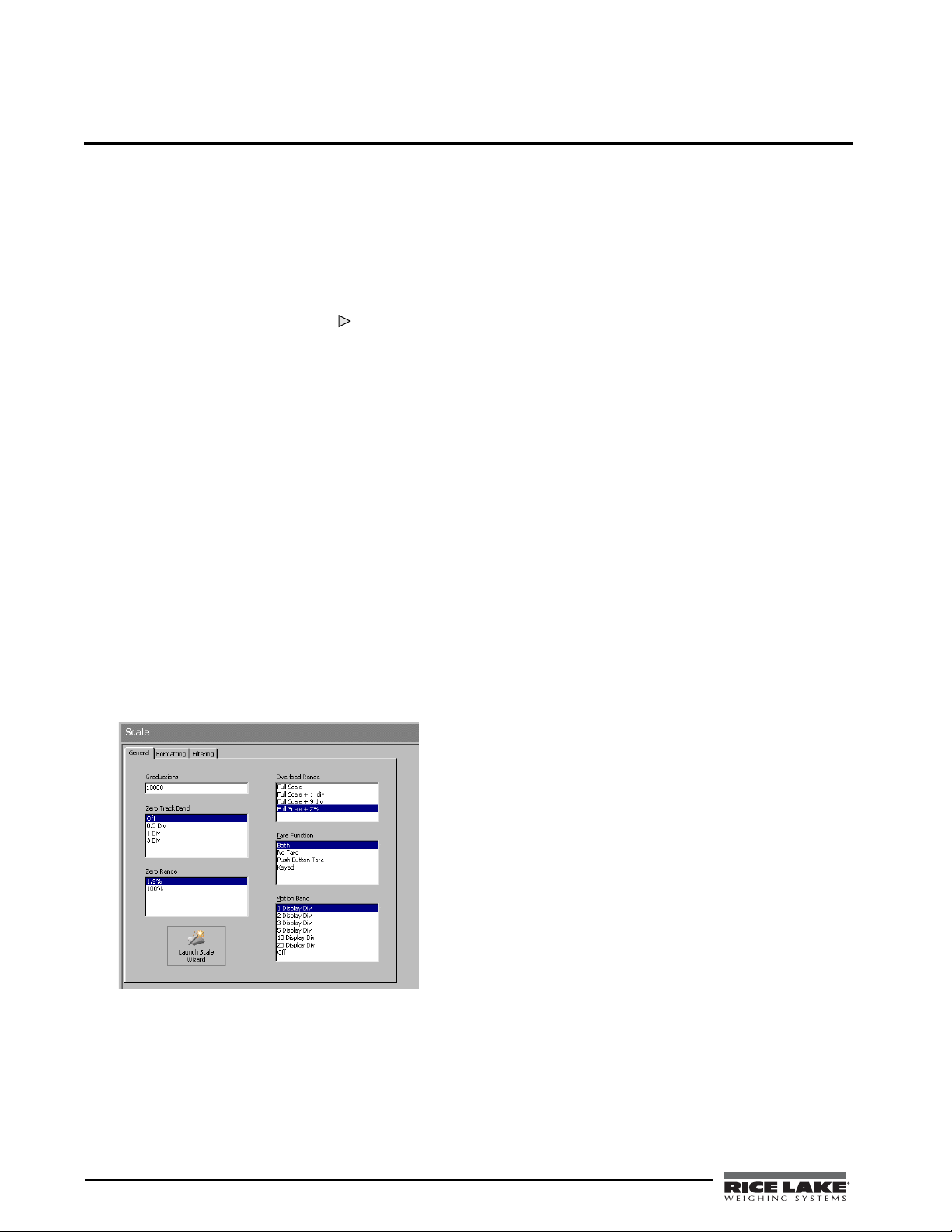
4. Start the
Figure 3-1 shows an example of one of the
Revolution program.
Revolution
configuration displays.
Revolution provide s online help for each of its
configuration displays. Parameter descriptions
provided in this manual for front panel configuration
can also be used when configuring the
Revolution: the interface is different, but the
Tra ce r AV using
parameters set are the same.
3.1.2 EDP Command Configuration
The EDP command set can be used to configure the
Tra ce r AV using a personal computer, terminal, or
remote keyboard. Like
configuration sends commands to the
port; unlike
Revolution, EDP commands ca n be sent
Revolution, EDP command
Tra ce r AV EDP
using any external device capable of sending ASCII
characters over a serial connection.
EDP commands duplicate the functions available
using the
Tra ce r AV front panel and provide some
functions not otherwise available. EDP commands can
be used to simulate pressing front panel keys, to
configure the
Tracer AV, or to dump lists of parameter
settings. See Section 5.0 on page 26 for more
information about using the EDP command set.
Figure 3-1. Sample Revolution Configuration Display
Revolution
supports both uploading and downloading
of configuration data. This capability allows
configuration data to be retrieved from one
Tra ce r AV ,
edited, then downloaded to another.
10 Tracer AV Installation Manual
Page 15
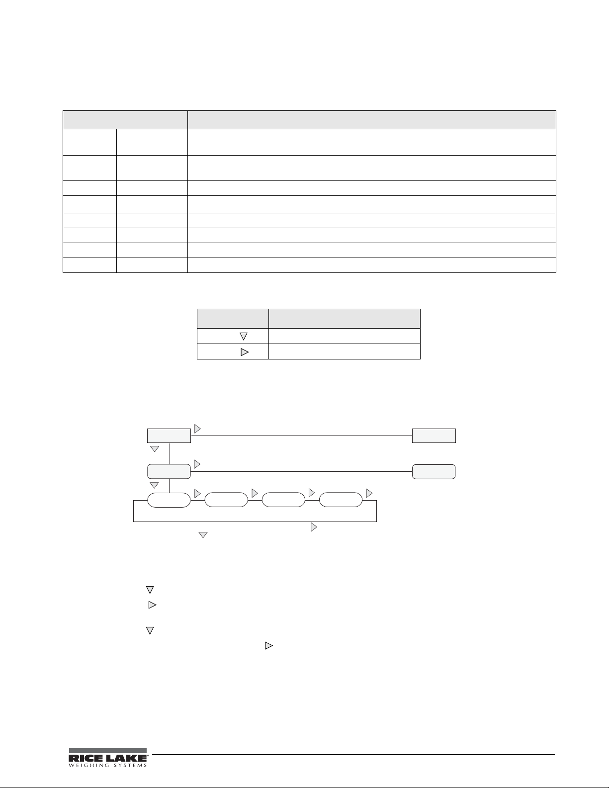
3.1.3 Front Panel Configuration
1st Level
Parameter
Default value
Value
1st Level
Parameter
2
nd
Level
Parameter
2
nd
Level
Parameter
Value
Value
When moving through values below the first menu, press UNITS to view the
selections. Press ZERO to set the parameter and move to the next parameter on the
leval above.
The Tracer AV can be configured using a series of menus viewed on the RD-1 display when the Tra ce r AV is in
setup mode. Table 3-1 summarizes the functions of each of the main menus.
Menu Menu Function
DEFCAL Default
Configuration
CONFIG Configuration Configure grads, zero tracking, zero range, motion band, overload, tare function, sample rate,
FORMAT Format Set format of primary and secondary units, display rate.
CALIBR Calibration
SERIAL Serial Configure EDP and printer serial ports.
PROGRM Program Set power-up mode, regulatory mode, and consecutive number values.
SETPNT Setpoint Configure Setpoints and digital outputs.
VERS Version Display installed software version number.
Select a 500lb or 300lb default configuration. You can also display and edit zero calibration a/d
count value, test weight value, and span calibration a/d count value.
and digital filtering parameters.
Calibrate
Tra cer AV. See Section 4.0 on page 23 for calibration procedures.
Table 3-1. Tra ce r AV Menu Summary
Button Function
Zero
Units
Move DOWN/ Increment Value
Move RIGHT/Next
Table 3-2. Button Functions in Setup Mode
The two-button numeric editor works as follows:
Press
Units to navigate RIGHT. Press Zero to drop DOWN or select from a list of values.
Figure 3-2. Setup Mode Menu Navigation
3.1.4 Setting Numeric Values For Parameters
1. Press Zero to immediately accept the current value and navigate to the next menu item.
2. Press
Units to enter edit mode.
The leftmost digit will flash to indicate it can be altered.
3. Press
4. When the value is correct, press
Zero to increment to the desired value.
Units to move to the next digit.
Tracer AV Installation Manual - Configuration 11
Page 16

3.1.5 Editing Integers
Figure 3-3. Editing Procedure for Numeric Values
Change Digit Selection
Increment Value/
Save Value Entered
And Return to Level
Above
XXXXXXX XXXXXXX
SETPNT PROGRM SERIAL CALIBR CONFIG FORMAT
VERS
XXXXXXX
DEFCAL
SELECT WV AL WSPAN WZERO
500lb
300lb
1. By pressing Units , navigate all the way to the
right (beyond all ‘-’
characters until there are no
segments flashing).
NOTE: The ‘-’ characters are placeholders for appending or
removing digits at the end of numbers that exceed the
six-digit display.
2. Press Zero to accept the modified value.
3.1.6 Editing Floating Point (Decimal Point Position)
1. By pressing Units , navigate all the way to the
right (beyond all ‘-’
characters until there are no
segments flashing).
2. Press
Zero to initialize editing of decimal point
position.
3. Press
Units to move the decimal point to the desired position.
The decimal point will move forward one position with the Units button and wrap around until the Zero
button is pressed to select the position.
4. When the decimal point is in the desired position, press
Zero .
3.2 Menu Structures and Parameter Descriptions
The following sections provide graphic representations of the Tracer AV menu structures. In the actual menu
structure, the settings you choose under each parameter are arranged horizontally. To save page space, menu
choices are shown in vertical columns. The factory default setting appears at the top of each column in bold type.
Most menu diagrams are accompanied by a table that describes all parameters and parameter values associated
with that menu. Default parameter values are shown in bold type.
3.2.1 Default Calibration Menu
Figure 3-4. Default Calibration Menu
DEFCAL Menu
Parameter Choices
SELECT 500lb
300lb
WZERO — Display and edit the zero calibration A/D count value.
WVAL — Display and edit the test weight value.
WSPAN — Display and edit the span calibration A/D count value.
500lb sets the scale to a primary of 500lb x 1 lb and a secondary of 250kg x .5 kg ;
SP1 trip=50lb; SP2=off; Dig Filter 1=8; Dig Filter 2=8; Dig Filter 3=8; Zero Tracking=3D
300lb sets the scale to a primary of 300lb x 1 lb and a secondary of 150kg x .5kg
SP1 trip=50lb; SP2=off; Dig Filter 1=8; Dig Filter 2=8; Dig Filter 3=8; Zero Tracking = 3D
DO NOT adjust this value after WSPAN has been set!
Description
12 Tracer AV Installation Manual
Table 3-3. Default Calibration Parameters
Page 17

3.2.2 Configuration Menu
XXXXXXX XXXXXXX
GRADS
1000
ZTRKBN ZRANGE
1.900000
MOTBAN
FS+2%
FS+9D
FS+1D
FS
OVRLOA
1
4
2
8
DIGFL1
32
16
64
1
4
2
8
32
16
64
1
4
2
8
32
16
64
number
DIGFL2 DIGFL3
BOTH
PBTARE
NOT ARE
KEYED
T AREFN
SETPNT PROGRM SERIAL CALIBR CONFIG FORMAT
8OUT
32OUT
16OUT
64OUT
DFSENS DFTHRH
2OUT
128OUT
4OUT
2DD
NONE
5DD
20DD
10DD
50DD
200DD
100DD
250DD
15HZ
60HZ
30HZ
7.5HZ
SMPRAT
VERS
DEFCAL
0
1
number number
number
CONFIG Menu
Parameter Choices
Level 2 submenus
GRADS 1000
number
ZTRKBN 0
number
ZRANGE 1.900000
number
Figure 3-5. Configuration Menu
Graduations. Specifies the number of full scale graduations. The value entered must be in
the range 1–100 000 and should be consistent with legal requirements and environmental
limits on system resolution.
To calculate GRADS, use the formula, GRADS = Capacity / Display Divisions.
Display divisions for primary and secondary units are specified on the FORMAT menu.
Automatically zeroes the scale when within the range specified, as long as the input is
within the ZRANGE and scale is at standstill. Specify the zero tracking band in ± display
divisions. Maximum legal value varies depending on local regulations.
NOTE: For scales using linear calibration, do not set the zero tracking band to a value
greater than that specified for the first linearization point.
Selects the range within which the scale can be zeroed. The 1.900000 default value is ±
1.9% around the calibrated zero point, for a total range of 3.8%. Indicator must be at
standstill to zero the scale. Use the default value for legal-for-trade applications.
Table 3-4. Configuration Menu Parameters
Description
Tracer AV Installation Manual - Configuration 13
Page 18

CONFIG Menu
Parameter Choices
MOTBAN 1
number
OVRLOA FS+2%
FS+1D
FS+9D
FS
SMPRAT 15HZ
30HZ
60HZ
7.5HZ
DIGFL1
DIGFL2
DIGFL3
8
16
32
64
1
2
4
DFSENS 8OUT
16OUT
32OUT
64OUT
128OUT
2OUT
4OUT
DFTHRH NONE
2DD
5DD
10DD
20DD
50DD
100DD
200DD
250DD
TAR EFN BOTH
NOTARE
PBTARE
KEYED
Description
Sets the level, in display divisions, at which scale motion is detected. If motion is not
detected for 1 second or more, the standstill symbol lights. Some operations, including
print, tare, and zero, require the scale to be at standstill. Maximum legal value varies
depending on local regulations.
If this parameter is set to 0, the standstill annunciator will be set continuously on, and
operations including zero, print, and tare will be performed regardless of scale motion. If 0
is selected, ZTRKBND must also be set to 0.
Overload. Determines the point at which the display blanks and an out-of-range error
message is displayed. Maximum legal value varies depending on local regulations.
Sample rate. Selects measurement rate, in samples per second, of the analog-to-digital
converter. Lower sample rate values provide greater signal noise immunity.
Digital filtering. Selects the digital filtering rate used to reduce the effects of mechanical
vibration from the immediate area of the scale.
Choices indicate the number of A/D conversions that are averaged to obtain the
displayed reading. A higher number gives a more accurate display by minimizing the
effect of a few noisy readings, but slows down the settling rate of the indicator. See
Section 6.6 on page 37 for more information on digital filtering.
Digital filter cutout sensitivity. Specifies the number of consecutive readings that must fall
outside the filter threshold (DFTHRH parameter) before digital filtering is suspended. If
NONE is selected, the filter is always enabled.
Digital filter cutout threshold. Specifies the filter threshold, in display divisions. When a
specified number of consecutive scale readings (DFSENS parameter) fall outside of this
threshold, digital filtering is suspended. If NONE is selected, the filter is always enabled.
Tare function. Enables or disables push-button and keyed tares. Possible values are:
BOTH:Both push-button and keyed tares are enabled
NOTARE:No tare allowed (gross mode only)
PBTARE:Push-button tares enabled
KEYED:Keyed tare enabled
Table 3-4. Configuration Menu Parameters (Continued)
14 Tracer AV Installation Manual
Page 19

3.2.3 Format Menu
XXXXXXX XXXXXXX
DSPDIV MULT UNITS DECPNT
0.453592
5D
2D
1D
number
PRIMAR SECNDR
6SEC
4SEC
3SEC
2.5SEC
2SEC
1.5SEC
750MS
500MS
250MS
8SEC
DSPRAT
DSPDIV UNITS DECPNT
KG
8.88888
888880
5D
2D
1D
LB
88888. 8
88888.8
8888.88
888.888
88.8888
888880
888888
88888.8
8888.88
888.888
88.8888
8.88888
T
TN
NONE
TN
KG
T
LB
SETPNT PROGRM SERIAL CALIBR CONFIG DEFCAL FORMAT
1SEC
VERS
OZ
OZ
G
G
NONE
Only used if
UNITS =NONE
Figure 3-6. Format Menu
FORMAT Menu
Parameter Choices Description
Level 2 submenus
PRIMAR DECPNT
DSPDIV
Specifies the decimal position, display divisions, and units used for the primary units. See
Level 3 submenu parameter descriptions.
UNITS
SECNDR DECPNT
DSPDIV
Specifies the decimal position, display divisions, units, and conversion multiplier used for
the secondary units. See Level 3 submenu parameter descriptions.
UNITS
MULT
DSPRAT 250MS
500MS
Display rate. Sets the update rate for displayed values. Values are in milliseconds (MS) or
seconds (SEC).
750MS
1SEC
1.5SEC
2SEC
2.5SEC
3SEC
4SEC
6SEC
8SEC
Table 3-5. Format Menu Parameters
Tracer AV Installation Manual - Configuration 15
Page 20

FORMAT Menu
Parameter Choices Description
Level 3 submenus
Primary Units (PRIMAR Parameter)
DECPNT 88888.8
888888
888880
8.88888
88.8888
888.888
8888.88
DSPDIV 5D
1D
2D
UNITS LB
KG
OZ
TN
T
G
NONE
Secondary Units (SECNDR Parameter)
DECPNT 88888.8
888888
888880
8.88888
88.8888
888.888
8888.88
DSPDIV 5D
1D
2D
UNITS KG
OZ
TN
T
G
NONE
LB
MULT 0.453592
Enter other
choices via
keyboard
Decimal point location. Specifies the location of the decimal point or dummy zeroes in the
primary unit display. Value should be consistent with local legal requirements.
Display divisions. Selects the minimum division size for the primary units displayed weight.
Specifies primary units for displayed and printed weight. Values are: LB=pound;
KG=kilogram; OZ=ounce; TN=short ton; T=metric ton; G=gram
NOTE: Indicators sold outside North America are configured with KG for both
primary and secondary units.
Decimal point location. Determines the location of the decimal point or dummy zeros in
the secondary unit display.
Display divisions. Selects the value of minimum division size of the displayed weight.
Specifies secondary units for displayed and printed weight. Values are: KG=kilogram;
OZ=ounce; TN=short ton; T=metric ton; G=gram; LB=pound.
Multiplier. Specifies the conversion factor by which the primary units are multiplied to
obtain the secondary units. The default is 0.453592, which is the conversion factor for
changing pounds to kilograms. See Section 6.5 on page 36 for a list of multipliers.
NOTE: Multipliers are pre-configured within the indicator. Manual entry is only
necessary when NONE is selected under UNITS.
To toggle between primary and secondary units, press the Units key.
16 Tracer AV Installation Manual
Table 3-5. Format Menu Parameters (Continued)
Page 21

3.2.4 Calibration Menu
XXXXXXX XXXXXXX
WZERO WV AL WSPAN
SETPNT PROGRM SERIAL CALIBR CONFIG FORMAT
REZERO
VERS
Press Zero key to
remove offset from
zero and span
calibrations
DEFCAL
XXXXXXX XXXXXXX
EOLDLY
000
number
EDP
BITS TERMIN BAUD
CR
9600
7ODD
7EVEN
8NONE
CR/LF
4800
2400
1200
600
300
SETPNT PROGRM SERIAL CALIBR CONFIG FORMAT
ECHO
ON
OFF
VERS
19200
38400
DEFCAL
See Section 4.0 on page 23 for calibration procedures.
Figure 3-7. Calibration Menu
CALIBR Menu
Parameter Choices Description
Level 2 submenus
WZERO — Display and edit the zero calibration A/D count value.
DO NOT adjust this value after WSPAN has been set!
WVAL — Display and edit the test weight value.
WSPAN — Display and edit the span calibration A/D count value.
REZERO —
Press Zero to remove an offset value from the zero and span calibrations.
Use this parameter only after WZERO and WSPAN have been set. See Section 4.2 on
page 24 for more information about using this parameter.
Table 3-6. Calibration Menu Parameters
3.2.5 Serial Menu
See Section 6.3 on page 34 for information about the Tra ce r AV serial data format.
Figure 3-8. Serial Menu
Tracer AV Installation Manual - Configuration 17
Page 22

SERIAL Menu
Parameter Choices Description
Level 2 submenus
EDP BAUD
BITS
TERMIN
EOLDLY
ECHO
Level 3 Submenus EDP Port and Printer Port
BAUD 9600
19200
38400
300
600
1200
2400
4800
BITS 8NONE
7EVEN
7ODD
TERMIN CR/LF
CR
EOLDLY 000
number
ECHO ON
OFF
Specifies settings for baud rate, data bits, termination characters, end-of-line delay, and echo
used by the EDP port.
Baud rate. Selects the transmission speed for the EDP or printer port.
Selects number of data bits and parity of data transmitted from the EDP or printer port.
Termination character. Selects termination character for data sent from the EDP or printer port.
End-of-line delay. Sets the delay period, in 0.1-second intervals, from when a formatted line is
terminated to the beginning of the next formatted serial output. Value specified must be in the
range 0-255, in tenths of a second (10 = 1 second).
NOTE: An EOL may be required for continuous transmission at slower baud rates to
ensure the receiving buffer is empty before another string is transmitted
This command enables or disables echoing of the serial commands sent to the indicator.
Table 3-7. Serial Menu Parameters
18 Tracer AV Installation Manual
Page 23

3.2.6 Program Menu
XXXXXXX XXXXXXX
PWRUPM
GO
OIML
REGULA
000000
number
CONSNU
DELAY
SETPNT PROGRM SERIAL CALIBR CONFIG FORMAT
000000
number
CONSTU
NTEP
CANADA
1
UID
VERS
DA TFMT
MMDDYY
DA TE
DDMMYY
YYMMDD
YYDDMM
DA TSEP
SLASH
DASH
SEMI
TIMFMT
12HOUR
TIME
24HOUR
TIMSEP
COLON
COMA
NONE
DEFCAL
Figure 3-9. Program Menu
PROGRM Menu
Parameter Choices Description
Level 2 submenus
PWRUPM GO
DELAY
REGULA NTEP
OIML
CANADA
NONE
Power up mode. In GO mode, the indicator goes into operation immediately after a brief power
up display test.
In DELAY mode, the indicator performs a power up display test, then enters a 30-second
warm up period. If no motion is detected during the warm up period, the indicator becomes
operational when the warm up period ends; if motion is detected, the delay timer is reset and
the warm up period repeated.
Regulatory mode. Specifies the regulatory agency having jurisdiction over the scale site.
OIML, NTEP, and CANADA modes allow a tare to be acquired at any weight greater than zero.
NONE allows tares to be acquired at any weight value.
OIML, NTEP, and CANADA modes allow a tare to be cleared only if the gross weight is at no
load. NONE allows tares to be cleared at any weight value.
NTEP and OIML modes allow a new tare to be acquired even if a tare is already present. In
CANADA mode, the previous tare must be cleared before a new tare can be acquired.
NONE, NTEP and CANADA modes allow the scale to be zeroed in either gross or net mode as
long as the current weight is within the specified ZRANGE. In OIML mode, the scale must be in
gross mode before it can be zeroed; pressing the ZERO key in net mode clears the tare.
UID 1 Specifies the unit identification number. Value specified can be any numeric value, up to six
digits.
DATE DATFMT
Allows selection of date format and date separator. See Level three parameter for descriptions.
DATSEP
TIME TIMFMT
Allows selection of time format and separator. See level three parameter for descriptions.
TIMSEP
CONSNU 000000
number
Consecutive numbering. Allows sequential numbering for print operations. The consecutive
number value is incremented following each print operation.
The initial value of this parameter is set to the start up value specified on the CONSTU
parameter. Changing either CONSTU or CONSNU immediately resets the consecutive number
used for printing.
CONSTU 000000
number
Consecutive number start up value. Specifies the initial consecutive number (CONSNU) value
used when the indicator is powered on.
Table 3-8. Program Menu Parameters
Tracer AV Installation Manual - Configuration 19
Page 24

PROGRM Menu
Parameter Choices Description
Level 3 submenus
DATFMT MMDDYY
DDMMYY
YYMMDD
DATSEP SLASH
DASH
SEMI
TIMFMT 24HOUR
12HOUR
TIMSEP COLAN
COMMA
Specifies the format used to display or print the date.
Specifies the date separator character.
Specifies the format used to display or print the time.
Specifies the time separator character.
Table 3-8. Program Menu Parameters (Continued)
20 Tracer AV Installation Manual
Page 25

3.2.7 Setpoint Menu
GROSS
NET
SETPT1
Same as SETPT1
XXXXXXX XXXXXXX
PROGRM SERIAL CALIBR CONFIG FORMAT
XXXXXXX
SETPNT
KIND
number
V ALUE
HIGHER
LOWER
TRIP
number
BNDVAL
INBAND
OUTBAND
number
HYSTER
OFF
ON
ENABLE
OFF
ON
ACCESS
If TRIP = HIGHER/
LOWER
SETPT2
VERS
DEFCAL
Figure 3-10. Setpoint Menu
SETPNT Menu
Parameter Choices Description
Level 2 submenus
SETPT1
SETPT2
ENABLE
KIND
Specifies settings for setpoint enable, kind, weight value, trip, and band value used by the
setpoint
VAL UE
TRIP
BNDVAL
Level 3 submenus
ENABLE OFF
Turns setpoint ON or OFF.
ON
KIND GROSS
NET
Specifies the setpoint kind and determines whether function is based on GROSS or NET
weight.
GROSS or NET setpoint kinds can be used.
VALUE number Displays and edits the setpoint value
TRIP HIGHER
LOWER
INBAND
OUTBND
Trips the setpoint when the weight is higher or lower than the setpoint value, or is within or
outside of the band value. LOWER means the output is active until you reach weight. If trip is
HIGHER, the output is active when the setpoint is met or exceeded. INBAND means the
output is active if the weight is within the band value. If trip is OUTBND, the output is active
when the weight is outside of the band value.
BNDVAL number The band value for either INBAND or OUTBND trip setpoints. BNDVAL is ignored unless trip is
set to INBAND or OUTBND.
HYSTER number Specifies a band around the setpoint value that must be exceeded before the setpoint, once
off, can trip on. If TRIP = HiGHER or LOWER.
ACCESS OFF
ON
Front panel access to setpoints. Specify OFF if setpoints will not be used. ON enables
operator to turn setpoints on/off, change value, or change BANDVAL via front panel entry
during weigh mode.
Table 3-9. Setpoint Menu Parameters
Tracer AV Installation Manual - Configuration 21
Page 26

3.2.8 Version Menu
XXXXXXX ALGOUT XXXXXXX XXXXXXX
VERS
DIGI N SETPNT PROGRM PFORMT SERIAL CALIBR CONFIG FORMAT
SOFTWR
REGVER
MODEL
1.08 1.01
AV
DEFCAL
The VERS menu is used to check the software version and reg version installed in the Tracer AV. You can also
check the model.
Figure 3-11. Version Menu
22 Tracer AV Installation Manual
Page 27

4.0 Calibration
XXXXXXX XXXXXXX
WZERO WV AL WSPAN
SETPNT PROGRM SERIAL CALIBR CONFIG FORMAT
REZERO
VERS
Zero
DEFCAL
XXXXXXX XXXXXXX
SETPNT PROGRM SERIAL CALIBR CONFIG FORMAT
VERS
XXXXXXX
DEFCAL
SELECT WV AL WSPAN WZERO
500lb
300lb
The Tra ce r AV can be calibrated using the Zero and Units keys, EDP commands, or the Revolution® configuration
utility. Each method consists of the following steps:
• Zero calibration
• Entering the test weight value
Figure 4-1. Calibration (CALIBR) Menu
You can also use the default calibration feature, which utilizes a more user-friendly procedure; however, not all
options are available in default calibration.
• Span calibration
• Optional rezero calibration for test weights
using hooks or other additional items.
Figure 4-2. Default Calibration (DEFCAL) Menu
4.1 Default Calibration
If you use a 500lb or 300lb scale, you can se lect it
from the
settings shown in Table 4-1. for 500lbs or Table 4-2.
for 300lbs.
DEFCAL menu. This automatically uses the
Primary 500lb x 1lb
Secondary 250kg x .5kg
SP1 Trip 50lb
SP2 Off
Digital Filter 8,8,8
Zero Tracking 3D
Table 4-1. 500lb scale settings
Primary 300lb x 1lb
Secondary 150kg x .5kg
SP1 Trip 50lb
SP2 Off
Digital Filter 8,8,8
Zero Tracking 3D
Table 4-2. 300lb scale settings
To calibrate the
Tra ce r AV using the Zero and Units
keys, do the following:
1. Place the
Tra ce r AV in setup mode
To enter setup mode, remove the setup switch
access screw on the
Tra cer AV (See Figure 2-3
4). Once the screw is removed, use a small
screwdriver to press the setup switch. The
display changes to show the word
DEFCAL.
2. Remove all weight from the scale platform. If
your test weights require hooks or other
items, place them on the scale.
3. Press the
4. Press the
Zero key to go to SELECT.
Units key to go to ze ro calibr ation
(WZERO).
5. Press the
indicator displays
Zero key to calibrate zero. The
*CAL* while calibration is in
progress. When complete, the A/D count for
the zero calibration is displayed. DO NOT
adjust this value after WSPAN has been set!
Zero again to save the zero calibration
Press
value and go to the next prompt (
WVAL).
Tracer AV Installation Manual - Calibration 23
Page 28

6. With WVAL displayed, press Zero to show
the stored calibration weight. Use the
procedure shown in Figure 3-3 12 to enter the
actual value of the test weights to be used for
the span calibration. Press
store the entered
calibration (
7. With
WSPAN displayed, place test weights on
WVAL value and go to span
WSPAN).
the scale and press
The indicator displays
Zero to calibrate span.
Zero again to
*CAL* while calibration
is in progress. When complete, the A/D count
for the span calibration is displayed. Press
Zero again to store the span calibration
value.
4.2 Standard Calibration
To calibrate the Tra ce r AV using the Zero and Units
keys, do the following:
1. Place the
To enter setup mode, remove the setup switch
access screw on the
4). Once the screw is removed, use a small
screwdriver or pen tip to press the setup
switch. The display changes to show the word
DEFCAL.
2. Remove all weight from the scale platform.
If your test weights require hooks or other
items, place them on the scale for zero
calibration.
3. Press the
CALIBR (see Figure 4-1). Press the Zero key
to go to zero calibration (WZERO).
4. With
calibrate zero. The indicator displays
while calibration is in progress. When
complete, the A/D count for the zero
calibration is displayed. DO NOT adjust this
value after WSPAN has been set! Press
again to save the zero calibration value and go
to the next prompt (
5. With
the stored calibration weight. Use the
procedure shown in Figure 3-3 12 to enter the
actual value of the test weights to be used for
the span calibration. Press
store the entered
calibration (
6. With
the scale and press Zero to calibrate span.
The indicator displays
is in progress. When complete, the A/D count
for the span calibration is displayed. Press
Zero again to store the span calibration
value and go to the next prompt (
Tra ce r AV in setup mode
Tracer AV (See Figure 2-3
Units key until the display reads
WZERO displayed, press Zero to
*CAL*
Zero
WVAL).
WVAL displayed, press Zero to show
Zero again to
WVAL value and go to span
WSPAN).
WSPAN displayed, place test weights on
*CAL* while calibration
REZERO).
7. The rezero function is used to remove a
calibration offset when hooks or other items
are used to hang the test weights.
• If no other apparatus was used to hang the
test weights during calibration, remove
the test weights and press
Units to
return to the CALIBR menu.
• If hooks or other items were used during
calibration, remove these and the test
weights from the scale. With all weight
removed, press
Zero to rezero the scale.
This function adjusts the zero and span
calibration values. The indicator displays
*CAL* while the zero and span calibrations
are adjusted. When complete, the adjusted
A/D count for the zero calibration is
displayed. Press
then press
Zero to save the value,
Units to return to the
CALIBR menu.
8. Press
Units until the display reads CONFIG,
and the display will exit the setup mode.
4.3 EDP Command Calibration
To calibrate the Trac er AV using EDP commands, the
EDP port must be connected to a terminal or personal
computer. See Section 2.3.3 on page 7 for EDP port
pin assignments; see Section 5.0 on page 26 for more
information about using EDP commands.
Once the
do the following:
Tra ce r AV is connected to the sending device,
1. Place the
reads
Tra ce r AV in setup mode (display
CONFIG) and remove all weight from the
scale platform. If your test weights require
hooks or other items, place them on the scale
for zero calibration.
2. Send the WZERO EDP command to calibrate
zero. The indicator displays
*CAL* while
calibration is in progress.
3. Place test weights on the scale and use the
WVAL command to enter the test weight
value in the following format:
WVAL=nnnnnn<CR>
4. Send the WSPAN EDP command to calibrate
span. The indicator displays *CAL* while
calibration is in progress.
5. To remove an offset value, clear all weight
from the scale, including hooks or other items
used to hang test weights, then send the
REZERO EDP command. The indicator
displays
*CAL* while the zero and span
calibrations are adjusted.
6. Send the KUPARROW EDP command to exit
setup mode.
24 Tracer AV Installation Manual
Page 29

4.4 Revolution
®
Calibration
To calibrate the Tra ce r AV using Revolution, the EDP
port must be connected to a PC running the
Revolution configuration utility.
Use the following procedure to calibrate the
AV
:
1. Select
Calibration Wizard from the Revolution
Tra ce r
tools menu.
2.
Revolution uploads calibration data from the
Tra ce r AV then presents the information in a
display like that shown in Figure 4-3.
Figure 4-3. Revolution Calibration Display
3. Enter the Value of Test Weight to be used for
span calibration then click OK.
4. The Zero Calibration dialog box prompts you
to remove all weight from the scale. Clear the
scale and click
NOTE: If your test weights require hooks or other items,
place them on the scale for zero calibration.
OK to begin zero calibration.
5. When zero calibration is complete, the Span
Calibration dialog box prompts you to place
test weights on the scale for span calibration.
Place tests weights on the scale then click
6. When calibration is complete, the
New Settings
OK.
fields of the Indicator Calibration display are
filled in. Click Exit to save the new values and
return to the Revolution main menu; to restore
the previous calibration values, click
Settings.
Restore
4.5 More About Calibration
The following topics provide additional information
about compensating for environmental factors
(Section 4.5.1) and diagnostic information for
determining expected zero and span coefficients.
4.5.1 Adjusting Final Calibration
Calibration may be affected by environmental factors
including wind, vibration, and angular loading. For
example, if the scale is calibrated with 1000 lb, a
strain test may determine that at 2000 lb the
calibration is 3 lb high. In this case, final calibration
can be adjusted by tweaking WVAL to 998.5 lb. This
adjustment provides a linear correction of 1.5 lb per
1000 lb.
To adjust the final calibration, return to the
prompt and press Zero to show the test weight
value. Press
Units to adjust calibration up or down.
Press Zero to save the value, then press
return to the CALIBR menu.
4.5.2 A/D Counts
Table 4-3 list s the ideal A/D counts that result from
input signals of 0–3.0 mV with zero deadload. Actual
values will typically be higher than the values shown
in Table 4-3, but the ideal values can be used when
calibrating the
Tra cer AV with no attached scale.
Input Signal (mV) Raw A/D Counts
0.0 mV/V 167,840
0.5 mV/V 335,613
1.0 mV/V 503,377
1.5 mV/V 671,143
2.0 mV/V 838,908
2.5 mV/V 1,100,668
3.0 mV/V 1,174,446
WVAL
Units to
Table 4-3. Ideal A/D Raw Counts
NOTE: When Raw A/D Count is displayed, the six most
significant digits appear. Scroll left or right to see the full
value.
Tracer AV Installation Manual - Calibration 25
Page 30

5.0 EDP Commands
The Tracer AV can be controlled by a personal
computer or remote keyboard connected to the EDP
port. Control is provided by a set of EDP commands
that can simulate front panel key press functions,
display and change setup parameters, and perform
reporting functions. The EDP port provides the
capability to print configuration data or to save that
data to an attached personal computer. This section
describes the EDP command set and procedures for
saving and transferring data using the EDP port.
5.1 The EDP Command Set
The EDP command set can be divided into five
groups: key press commands, reporting commands,
the RESETCONFIGURATION special function
command, parameter setting commands, and transmit
weight data commands.
When the
responds with the message
verifies that the command was received and has been
executed. If the command is unrecognized or cannot
be executed, the indicator responds with
The following sections list the commands and
command syntax used for each of these groups.
5.1.1 Key Press Commands
Key press EDP commands (see Table 5-1) simulate
pressing the keys on the 2-button keypad. Most
commands can be used in both setup and weighing
mode. Several of the commands serve as “pseudo”
keys, providing functions that are not represented by a
key on the front panel.
For example, to enter a 15-pound tare weight using
EDP commands:
Tracer AV processes an EDP command, it
OK. The OK response
??.
1. Type K1 and press
ENTER
2. Type K5 and press ENTER
3. Type KTARE and press ENTER
The display shifts to net mode when the tare is
entered.
Command Function
KZERO In weighing mode, press the Zero key
KGROSSNET In weighing mode, press the GROSS/
NET key
KGROSS Go to gross mode*
KNET Go to net mode*
KTARE Press the TARE key
KUNITS In weighing mode, press the Units key
KPRIM Go to primary units*
KSEC Go to secondary units*
KPRINT In weighing mode, press the PRINT key
KLEFTARROW In setup mode, move left in the menu
KRIGHTARROW In setup mode, move right in the menu
KUPARROW In setup mode, move up in the menu
KDOWNARROW In setup mode, move down in the menu
KTIME Press the TIME/DATE key once*
KDATE Press the TIME/DATE key twice*
KDISPTARE Press the DISPLAY TARE key*
KCLR Press the CLEAR key*
K0 Press number 0 (zero)*
K1 Press number 1*
K2 Press number 2*
K3 Press number 3*
K4 Press number 4*
K5 Press number 5*
K6 Press number 6*
K7 Press number 7*
K8 Press number 8*
K9 Press number 9*
KDOT Press the decimal point (.)*
KENTER Press the ENTER key
* Pseudo keys
26 Tracer AV Installation Manual
Table 5-1. EDP Key Press Commands
Page 31

5.1.2 Reporting Commands
Reporting commands (see Table 5-2) send specific
information to the EDP port. These commands can be
used in both setup mode and normal mode.
Command Function
DUMPALL List all parameter values
VERSION
P Write current displayed weight with units
ZZ Write current weight and annunciator
S Write one frame of stream format. See
5.1.3 The RESETCONFIGURATION Command
Tra ce r AV software version
identifier. See Section 6.2 on page 33 for
more information.
status. See Section 6.2 on page 33 for
more information.
Table 5-12 on page 30 for information
about the SX and EX commands.
Table 5-2. EDP Reporting Commands
The RESETCONFIGURATION command can be used to
restore all configuration parameters to their default
values. Before issuing this command, the
Tra ce r AV
must be placed in test mode (press and hold setup
switch for approximately three seconds to show TEST
menu).
This command is equivalent to using the DEFLT
function on the TEST menu. See Section 6.7 on
page 39 for more information about test mode and
using the TEST menu.
NOTE: All load cell calibration settings are lost when the
RESETCONFIGURATION command is run.
5.1.4 Parameter Setting Commands
Parameter setting commands allow you to display or
change the current value for a particular configuration
parameter (Tables 5-3 through 5-11).
Current configuration parameter settings can be
displayed in either setup mode or normal mode using
the following syntax:
command<ENTER>
Most parameter values can be changed in setup mode
only. Use the following command syntax when
changing parameter values:
command=value<ENTER>
where value is a number or a parameter value. Use no
spaces before or after the equal (=) sign. If you type an
incorrect command or value, the display reads
??.
Changes to the parameters are saved as they are
entered but typically do not take effect until you exit
setup mode.
For example, to set the motion band parameter to 5,
type the following:
MOTBAND=5D<ENTER>
5.1.5 Soft Reset
The RS command will reset the Tracer AV without
losing configuration and calibration. It does reset
consecutive number.
Command Description Values
DEFCAL Default Calibration 300lb, 500lb
GRADS Graduations 1–100 000
ZTRKBND Zero track band OFF, 0.5D, 1D, 3D
ZRANGE Zero range 1.9%, 100%
MOTBAND Motion band 1D, 2D, 3D, 5D, 10D, 20D, OFF
OVRLOAD Overload FS+2%, FS+1D, FS+9D, FS
SMPRAT Sample rate 15HZ, 30HZ, 60HZ, 7.5HZ
DIGFLTR1
DIGFLTR2
DIGFLTR3
DFSENS Digital filter cutout sensitivity 2OUT, 4OUT, 8OUT, 16OUT, 32OUT, 64OUT, 128OUT
DFTHRH Digital filter cutout threshold NONE, 2DD, 5DD, 10DD, 20DD, 50DD, 100DD, 200DD, 250DD
TAREFN Tare function BOTH, NOTARE, PBTARE, KEYED
Digital filtering 1, 2, 4, 8, 16, 32, 64
Table 5-3. CONFIG EDP Commands
Tracer AV Installation Manual - EDP Commands 27
Page 32

Command Description Values
PRI.DECPNT Primary units decimal position 8.88888, 88.8888, 888.888, 8888.88, 88888.8, 888888, 888880
PRI.DSPDIV Primary units display divisions 1D, 2D, 5D
PRI.UNITS Primary units LB, KG, OZ, TN, T, G, NONE
SEC.DECPNT Secondary units decimal position 8.88888, 88.8888, 888.888, 8888.88, 88888.8, 888888, 888880
SEC.DSPDIV Secondary units display divisions 1D, 2D, 5D
SEC.UNITS Secondary units LB, KG, OZ, TN, T, G, NONE
SEC.MULT Secondary units multiplier 0.00000–9999.99
DSPRATE Display rate 250MS, 500MS, 750MS, 1SEC, 1.5SEC, 2SEC, 2.5SEC, 3SEC,
4SEC, 6SEC, 8SEC
Table 5-4. FORMAT EDP Commands
Command Description Values
WZERO Zero calibration —
WVAL Test weight value test_weight_value
WSPAN Span calibration —
REZERO Rezero —
LC.CD Set deadload coefficient value
LC.CW Set span coefficient value
Table 5-5. CALIBR EDP Commands
Command Description Values
EDP.BAUD EDP port baud rate 300, 600, 1200, 2400, 4800, 9600, 19200, 38400
EDP.BITS EDP port data bits/parity 8NONE, 7EVEN, 7ODD
EDP.TERMIN EDP port termination character CR/LF, CR
EDP.EOLDLY EDP port end-of-line delay 0–255 (0.1-second intervals)
EDP.ECHO EDP port echo ON, OFF
PRN.BAUD Printer port baud rate 19200
PRN.BITS Printer port data bits/parity 8NONE, 7EVEN, 7ODD
PRN.TERMIN Printer port termination character CR/LF, CR
PRN.EOLDLY Printer port end-of-line delay 0–255 (0.1-second intervals)
PRN.ECHO Printer port echo ON, OFF
STREAM Streaming port OFF, EDP, PRN
STRRTE Stream rate INDUST, LFT
PRNDEST Print destination EDP, PRN
Table 5-6. SERIAL EDP Commands
Command Description Values
PWRUPMD Power up mode GO, DELAY
REGULAT Regulatory compliance NTEP, OIML, CANADA, NONE
Table 5-7. PROGRM EDP Commands
28 Tracer AV Installation Manual
Page 33

Command Description Values
CONSNUM Consecutive number 0–999 999
CONSTUP Consecutive number start-up value 0–999 999
DATEFMT Date format MMDDYY, DDMMYY, YYMMDD, YYDDMM
DATESEP Date separator SLASH, DASH, SEMI
TIMEFMT Time format 12HOUR, 24HOUR
TIMESEP Time separator COLON, COMMA
Table 5-7. PROGRM EDP Commands
Command Description Val ues
GFMT Gross demand print format string
NFMT Net demand print format string
Table 5-8. PFORMT EDP Commands
Command Description Val ues
SP1 SP2
SP1.ENABLE SP2.ENABLE Setpoint enable OFF, ON
SP1.KIND SP2.KIND Setpoint kind GROSS, NET
SP1.VALUE SP2.VALUE Setpoint value number
SP1.TRIP SP2.TRIP Trip Higher, Lower, Inband, Outbnd
SP1.BNDVAL SP2.BNDVAL Band value number
SP1.HYSTER SP2.HYSTER Hysteresis number
SP1.ACCESS SP2.ACCESS Setpoint access OFF, ON
Table 5-9. SETPNTS EDP Commands
Command Description Values
DIGIN1
DIGIN2
Digital input function OFF, ZERO, TARE, NT/GRS, UNITS, DSPTAR, PRINT, CLRCN,
KBDLOC, HOLD, NEWID
Table 5-10. DIG IN EDP Commands
Command Description Values
SOURCE Analog output source GROSS, NET
OFFSET Zero offset 0%, 20%
ERRACT Error action FULLSC, HOLD, ZEROSC
MIN Minimum value tracked 0–999 999
MINNEG Minimum negative OFF, ON
MAX Maximum value tracked 0–999 999
MAXNEG Maximum negative OFF, ON
TWZERO Zero calibration 0–16 383
TWSPAN Span calibration 0–16 383
Table 5-11. ALGOUT EDP Commands
Tracer AV Installation Manual - EDP Commands 29
Page 34

5.1.6 Normal Mode Commands
The serial transmit weight data commands (see Table 5-12) transmit data to the EDP port on demand. The SX
and EX commands are valid only in normal operating mode; all other commands are valid in either setup or
normal mode.
Command Description Response Format
UID Set unit ID nnnnnnn
SD Set date MMDDYY, DDMMYY, YYMMDD (enter using DATEFMT
specified)
ST Set time hhmm (enter using 24-hour format)
SX Start EDP streaming OK or ??
EX Stop EDP streaming OK or ??
RS Reset system —
XG Transmit gross weight in displayed units nnnnnn UU
XN Transmit net weight in displayed units
XT Transmit tare weight in displayed units
XG2 Transmit gross weight in non-displayed units
XN2 Transmit net weight in non-displayed units
XT2 Transmit tare weight in non-displayed units
XE Query system error conditions nnnnn nnnnn
where nnnnnn is the weight value, UU is the units.
See Section 6.1.2 on page 33 for detailed information about
the XE command response format.
Table 5-12. Normal Mode Commands
30 Tracer AV Installation Manual
Page 35

5.2 Saving and Transferring Data
Connecting a personal computer to the Tra ce r AV EDP
port allows you to save configuration data to the PC or
to download configuration data from the PC to a
Tra ce r AV. The following sections describe the
procedures for these save and transfer operations.
5.2.1 Saving Tra ce r AV Data to a Personal Computer
Configuration data can be saved to a personal
computer connected to the EDP port. The PC must be
running a communications program such as
PROCOMMPLUS
information about serial communications wiring and
EDP port pin assignments.
When configuring the
values set for the BAUD and BITS parameters on the
SERIAL menu match the baud rate, bits, and parity
settings configured for the serial port on the PC. Set
the PRNDEST parameter to EDP.
To save all configuration data, place the
setup mode and send the DUMPALL EDP command.
Tra ce r AV responds by sending all configuration
The
parameters to the PC as ASCII-formatted text.
®
. See Section 2.3.3 on page 7 for
Tra ce r AV , ensure that the
Tra ce r AV in
5.2.2 Downloading Configuration Data from PC to
Tra ce r AV
Configuration data saved on a PC or floppy disk can
be downloaded from the PC to a
procedure is useful when a number of
similar configurations are set up or when a
Tracer AV. This
Tra ce r AV s with
Tra ce r AV
is replaced.
T o download confi guration data, connect the P C to the
EDP port as described in Section 5.2.1. Place the
Tra ce r AV in setup mode and use the PC
communications software to send the saved
configuration data to the
complete, calibrate the
Tra ce r AV. When transfer is
Tra ce r AV as described in
Section 4.0.
NOTES:
• Calibration settings are included in the
configuration data downloaded to the Tra ce r
AV
. If the receiving Trace r AV is a direct
replacement for another
Tra ce r AV and the
attached scale is not changed, recalibration is
not required.
• When downloading configurations that
include changed serial communications
settings, edit the data file to place the serial
communications changes at the end of the
file. Communication between the PC and
Tra ce r AV will be lost once the Trace r AV
receives settings for baud rate (BAUD
parameter) or data bits and parity (BITS
parameter) that do not match those configured
for the PC.
Tracer AV Installation Manual - EDP Commands 31
Page 36

6.0 Appendix
6.1 Error Messages
The Tra cer AV provides a number of error messages. When an error occurs, the message is shown on the remote
display. Error conditions can also be checked remotely by using the XE EDP command as described in
Section 6.1.2 on page 33.
6.1.1 Displayed Error Messages
The Tracer AV provides a number of front panel error mess ages to assist in problem diagnosis. Table 6-1 lists
these messages and their meanings.
Error Message Description Solution
E A/D A/D physical error Call Rice Lake Weighing Systems (RLWS) Service.
EEEROM EEPROM physical error
EVIREE Virgin EEPROM Use TEST menu to perform DEFLT (restore defaults) procedure, then
EPCKSM Parameter checksum error
EACKSM A/D calibration checksum error A/D converter requires recalibration. Call RLWS Service.
EFCKSM Printer format checksum error Call RLWS Service.
ELCKSM Load cell calibration checksum error Recalibrate load cells.
EIDATA Internal RAM checksum error Call RLWS Service.
E REF A/D reference error A/D converter requires recalibration. Call RLWS Service.
ERROR Internal program error Check configuration. Run XE command (see Section 6.1.2 on
OVERFL Overflow error Weight value too large to be displayed.
------ Gross > overload limit Gross value exceeds overload limit. Check configuration or signal
______ A/D underrange A/D reading < –4 mV. Check scale for binding or damage.
RNGERR GRADS > 100,000
WVAL > 100,000
EEPERR EEPROM Error Call Rice Lake Weighing Systems (RLWS) for service.
recalibrate load cells.
page 33) to determine error type.
Call RLWS Service if unable to clear error by cycling power or if error
recurs.
input level. Overload can be caused by input signal > 45 mV or
common mode voltage > 950 mV.
Only shows up in Config mode.
32 Tracer AV Installation Manual
Table 6-1. Tracer AV Error Messages
Page 37

6.1.2 Using the XE EDP Command
The XE EDP command can be used to remotely query
Tra ce r AV for the error conditions shown on the
the
front panel. The XE command returns two 5-digit
numbers in the format:
xxxxx yyyyy
where xxxxx contains a decimal represen tation of any
existing error conditions as described in Table 6-2.
If more than one error condition exists, the number
returned is the sum of the values representing the error
conditions. For example, if the XE command returns
the number 1040, this value represents the sum of an
A/D reference error (1024) and an A/D calibration
checksum error (16).
The second number returned (
yyyyy) uses the same bit
assignments as shown in T able 6-2 to indicate whether
the test for the error condition was run. For example,
the value
yyyyy = 50815 represents the decimal
eq u i v a le n t o f t h e b in a r y v a l u e 110 0 0 11 0 0 111 1111.
Using the bit assignments in Table 6-2 , this value
indicates all tests were run.
Error
Code
0x0001
0x0002
0x0004
0x0008
0x0010
0x0020
0x0040
0x0080
0x0100
0x0200
0x0400
0x0800
0x1000
0x2000
0x4000
0x8000
0x10000 - 0x80000000
EEPROM Error 0000 0000 0000 0001
Virgin EEPROM 0000 0000 0000 0010
Config Parameter Checksum 0000 0000 0000 0100
Load Cell Checksum 0000 0000 0000 1000
A/D Calibration Checksum 0000 0000 0001 0000
Print Formats Checksum 0000 0000 0010 0000
XA Internal RAM Error 0000 0000 0100 0000
External RAM Error 0000 0000 1000 0000
Reserved 0000 0001 0000 0000
ADC Physical Error 0000 0010 0000 0000
ADC Reference 0000 0100 0000 0000
Count Error 0000 1000 0000 0000
Reserved 0001 0000 0000 0000
Display Range 0010 0000 0000 0000
ADC Range 0100 0000 0000 0000
Gross Limit 1000 0000 0000 0000
Table 6-2. Error Codes Returned on XE Command
Description Binary Value
Reserved
6.2 Status Messages
Two EDP commands, P and ZZ, can be used to
provide status about the
are described in the following sections.
6.2.1 Using the P EDP Command
The P EDP command returns the current displayed
weight value to the EDP port, along with the units
identifier. If the indicator is in an underrange or
overload condition, the weight value is replaced with
&&&&&& (overload) or :::::: (underrange).
6.2.2 Using the ZZ EDP Command
The ZZ EDP command can be used to remotely query
which annunciators are currently displayed. The ZZ
command returns the currently displayed weight and a
decimal number representing the LED annunciators
currently lit. The format of the returned data is:
wwwwww uu zzz
where wwwwww uu is the current displayed weight and
units,
zzz is the annunciator status value (see
Table 6-3). If more than one annunciator is lit, the
second number returned is the sum of the values
representing the active annunciators.
Example: If the annunciator status value returned on
the ZZ command is 145, the gross, standstill, and lb
annunciators are lit. 145 represents the sum of the
values for the standstill annunciator (128), gross mode
annunciator (16), and the lb/primary units annunciator
(1).
Decimal
Value
1 lb/primary units
2kg/secondary units
16 Gross
32 Net
64 Center of zero
128 Standstill
Table 6-3. Status Codes Returned on the ZZ Command
Tra ce r AV. These commands
Annunciator
Tracer AV Installation Manual - Appendix 33
Page 38

6.3 Continuous Output (Stream) Format
<STX> <POL> <wwwwwww> <UNIT> <G/N> <S> <TERM>
ASCII 02
(decimal)
Weight data: 7 digits, right-justified, with
decimal point, l eading zer o s upr e ssion.
Overload = ^^^^^^^
Underrange = ] ] ] ] ] ] ]
Display overflow = OVERFL
LB = pounds
KG = kilogram
TN = ton
GM = grams
OZ = ounces
<space> = none
G = Gross
N = Net
Status:
< space > = valid
I = Invalid
M = Motion
O = Over/under range
Polarity:
< space
> = Positive
<–> = Negative
<^> = Overload
<]> = Underrange
<CR> <LF>
or <CR>
ASCII 13, 10
(decimal)
Z = Center of zero
Figure 6-1 shows the continuous output format sent from the Tracer AV Serial port to the Remote Display.
Note: In Setup mode, the text display message follows the following format: <100DM><Time M/S><Text!> or
<100DMText!>.
Figure 6-1. Continuous Output Data Format
34 Tracer AV Installation Manual
Page 39

6.4 Front Panel Display Characters
-9 EQ
.: FR
/; GS
0< HT
1= %IU
&2 >J V
‘
3? KW
(4 @L X
)5 AM Y
*6 BN Z
+7 CO [
,8 DP \
.
Figure 6-2 shows the 7-segment LED character set used to display alphanumeric characters on the Tra cer AV
front panel.
Figure 6-2. Trac er AV Display Characters
Tracer AV Installation Manual - Appendix 35
Page 40

6.5 Conversion Factors for Secondary Units
The Tracer AV has the capability to mathematically
convert a weight into many different types of units
and instantly display those results with a press of the
Units key .
Secondary units can be specified on the FORMAT
menu using the SECNDR parameter, or by using EDP
commands.
NOTES:
• Multipliers are preconfigured within the
Tra ce r AV. Manual entry is only necessary
when NONE is selected under UNITS. Long
tons and grain units listed in Table 6-4 cannot
be directly specified as primary or secondary
units. For these or other unlisted units of
weight, specify NONE under UNITS.
• Ensure that the secondary decimal point
position is set appropriately for the scale
capacity in the secondary units. If the
converted value requires more digits than are
available, the indicator will display an
overflow message (
• For example, if the primary units are short
tons, secondary units are pounds, and the
secondary decimal point is set to 8888.88, the
indicator will overflow if 5 tons or more are
applied to the scale. With 5 tons applied, and a
conversion factor of 2000, the secondary
unit’s display needs five digits to the left of
the decimal point to display the 10000 lb
secondary units value.
OVERFL).
Primary Unit x Multiplier Secondary Unit
grains 0.064799 grams
0.002286 ounces
0.000143 pounds
0.000065 kilograms
ounces 437.500 grains
28.3495 grams
0.06250 pounds
0.02835 kilograms
pounds 7000.00 grains
453.592 grams
16.0000 ounces
0.453592 kilograms
0.000500 short tons
0.000446 long tons
0.000453 metric tons
short tons 2000.00 pounds
907.185 kilograms
0.892857 long tons
0.907185 metric tons
grams 15.4324 grains
0.035274 ounces
0.002205 pounds
0.001000 kilograms
kilograms 15432.4 grains
35.2740 ounces
1000.00 grams
2.20462 pounds
0.001102 short tons
0.000984 long tons
0.001000 metric tons
metric tons 2204.62 pounds
1000.00 kilograms
1.10231 short tons
0.984207 long tons
long tons 2240.00 pounds
1016.05 kilograms
1.12000 short tons
1.01605 metric tons
NOTE: Multipliers in italics are preconfigured
36 Tracer AV Installation Manual
Table 6-4. Conversion Factors
Page 41

6.6 Digital Filtering
1
4
2
8
DIGFL1
32
16
64
1
4
2
8
DIGFL2
32
16
64
1
4
2
8
DIGFL3
32
16
64
8OUT
32OUT
16OUT
64OUT
DFSENS DFTHRH
2OUT
128OUT
4OUT
2DD
NONE
5DD
20DD
10DD
50DD
200DD
100DD
250DD
DIGFL1= n1 DIGFL2= n2 DIGFL3= n3
3rd Stage
Filter A verage
2nd Stage
Filter A verage
1st Stage
Filter A verage
Displayed
Value
n3
2nd Stage
Filter A verages
n2
1st Stage
Filter A verages
n1
A/D Readings
The Tracer AV uses averaged digital filtering to reduce the effect of vibration on weight readings. Adjustable
threshold and sensitivity functions allow quick settling by suspending filter averaging, allowing the weight
reading to jump to the new value. Figure 6-3 shows the digital filter parameters on the CONFIG menu.
Figure 6-3. Digital Filtering Parameters on the Configuration (CONFIG) Menu
Figure 6-4. Flow Diagram for Trace r AV Digital Filters
6.6.1 DIGFLx Parameters
The first three digital filtering parameters, DIGFL 1,
DIGFL2, and DIGFL3, are configurable filter stages
that control the effect of a single A/D reading on the
displayed weight. The value assigned to each
parameter sets the number of readings received from
the preceding filter stage before averaging (see
6.6.2 DFSENS and DFTHRH Parameters
The three digital filters can be used by themselves to
eliminate vibration effects, but heavy filtering also
increases settling time. The DFSENS (digital filter
sensitivity) and DFTHRH (digital filter threshold)
parameters can be used to temporarily override filter
averaging and improve settling time:
Figure 6-4).
The overall filtering effect can be expressed by adding
the values assigned to the three filter stages:
DIGFL1 + DIGFL2 + DIGFL3
For example, if the filters are configured as
DIGFL1=4, DIGFL2=8, DIGFL3=8, the overall
filtering effect is 20 (4 + 8 + 8). With this
configuration, each A/D reading has a 1-in-20 effect
on the displayed weight value. Setting the filters to 1
effectively disables digital filtering.
• DFSENS specifies the number of consecutive
scale readings that must fall outside the filter
threshold (DFTHRH) before digital filtering
is suspended.
• DFTHRH sets a threshold value, in display
divisions. When a specified number of
consecutive scale readings (DFSENS) fall
outside of this threshold, digital filt ering is
suspended. Set DFTHRH to NONE to turn off
the filter override.
Tracer AV Installation Manual - Appendix 37
Page 42

6.6.3 Setting the Digital Filter Parameters
Fine-tuning the digital filter parameters greatly improves Tracer AV performance in heavy-vibration
environments. Use the following pr ocedure to dete rmine vibration effects on the scale and optimize the digital
filtering configuration.
1. In setup mode, set all three digital filters (DIGFL1, DIGFL2, DIGFL3) to 1. Set DFTHRH to NONE.
Return the
Tra ce r AV to normal mode.
2. Remove all weight from the scale, then watch the indicator display to determine the magnitude of
vibration effects on the scale. Record the weight below which all but a few readings fall. This value is
used to calculate the DFTHRH parameter value in Step 4.
For example, if a heavy-capacity scale produces vibration-related readings of up to 50 lb, with
occasional spikes to 75 lb, record 50 lb as the threshold weight value.
3. Place the
Tra ce r AV in setup mode and set the digital filters (DIGFLx) to eliminate the vibration effects
on the scale. (Leave DFTHRH set to NONE.) Reconfigure as necessary to find the lowest effective
values for the DIGFLx parameters.
4. With optimum values assigned to the DIGFLx parameters, calculate the DFTHRH parameter value by
converting the weight value recorded in Step 2 to display divisions:
threshold_weight_value / DSPDIV
In the example in Step 2, with a threshold weight value of 50 lb and a display division value of 5lb: 50 /
5lb = 10DD.
DFTHRH should be set to 10DD for this example.
5. Finally, set the DFSENS parameter high enough to ignore transient peaks. Longer transients (typically
caused by lower vibration frequencies) will cause more consecutive out-of-band readings, so DFSENS
should be set higher to counter low frequency transients.
Reconfigure as necessary to find the lowest effective value for the DFSENS parameter.
38 Tracer AV Installation Manual
Page 43

6.7 Test Mode
A/DTST
TEST
ADOFFS
ADGAIN
DEFLT
In addition to normal and setup modes, test mode
provides a number of diagnostic functions for the
Tra ce r AV , including:
• Display raw A/D count
• Reset configuration parameters to default
values
• A/D internal calibration
NOTE: Test mode is intended for factory use only.
Figure 6-5. Test Mode Menu
TEST Menu
Function Description
A/DTST Display A/D test
Press and hold Enter key to display raw count from A/D converter.
DEFLT Default parameters
Press setup switch and Enter key at the same time to reset configuration and calibration parameters to factory
default values. Load cells must be recalibrated before using the
Table 6-5. Test Mode Menu Functions
To enter test mode, press and hold the setup switch
until the front panel display shows the word
After about three seconds, the test mode display
automatically shifts to the first test menu function,
A/DTST.
Figure 6-5 shows the Test Menu structure; Table 6-5
summarizes the test menu functions.
TEST.
Tra cer AV (see Section 4.0 on page 23).
Tracer AV Installation Manual - Appendix 39
Page 44

6.8 Regulatory Mode Functions
REGULAT
Parameter Value
NTEP zero or negative no no action ZERO
CANADA zero or negative no no action TARE
OIML zero or negative no no action ZERO
NONE zero or negative no TARE ZERO
Weight on Scale Ta re i n Sys tem
yes CLEAR TARE
positive no TARE
yes TARE
yes CLEAR TARE
positive no TARE
yes no action
yes CLEAR TARE ZERO and CLEAR TARE
positive no TARE ZERO
yes TARE ZERO and CLEAR TARE
yes CLEAR TARE
positive no TARE
yes CLEAR TARE
Front Panel Key Function
TARE ZERO
Table 6-6. TARE and ZERO Key Functions for REGULAT Parameter Settings
6.9 LED Functions
The following is a list of diagnostic LEDs for the
Tra ce r AV. See Figure 2-4 5 for locations on the
Tra ce r AV CPU board.
Serial Port Status
LED1 (EDP Port) Flashing red = TXD activity
Flashing green = RXD activity
On steady or off = No activity
LED2 (PRN Port) Flashing red = TXD activity
Flashing green = RXD activity
On steady or off = No activity
Power Supply
LED (+5AV) Excitation/ADC supply on
LED (+5V & +3.3V) Digital logic supply on
Operation Status
LEDHB (Microprocessor) Flashing green = Active
Red = Fault
LED AD (ADC) Green = Active
Red = Fault
LED MEM (Memory Test) Green = Pass
Red = Fail
LED ANA Red = Not Implemented
(Analog Option Card)
Digital Input/Output Status
DO 1 (Digital Out 1) On when lit (active low)
DO 2 (Digital Out 2) On when lit (active low)
DI 1 (Digital In 1) On when lit (active low)
DI 2 (Digital In 2) On when lit (active low)
40 Tracer AV Installation Manual
Page 45

6.10 Specifications
Power
Line Voltages 115 or 230 VAC
Frequency 50 or 60 Hz
Power Consumption 1.5 A @ 115 VAC (8W)
0.75 A @ 230 VAC (8W)
Fusing 2.5 A 5 x 20 mm fuse
Analog Specifications
Full Scale Input Signal Up to 22.5 mV
Excitation Voltage +5V single sided
8 x 350 or 16 x 700 load cells
Sense Amplifier Differential amplifier with
4- and 6-wire sensing
Analog Signal
Input Range –0.5 mV/V to +4.5 mV/V
Analog Signal
Sensitivity 0.3 V/graduation minimum,
1.5 V/grad recommended
Input Impedance 200 M, typical
Noise (ref to input) 0.3 V p-p with digital filters at 4-4-4
Internal Resolution 8,000,000 counts
Display Resolution 100 000 dd
Measurement Rate Up to 60 measurements/sec
Input Sensitivity 10 nV per internal count
System Linearity Within 0.01% of full scale
Zero Stability 150 nV/°C, maximum
Span Stability 3.5 ppm/°C, maximum
Calibration Method Software, constants stored in
EEPROM
Common Mode
Voltage –2.35 to +3.45 V, referred to ground
Rejection 130 dB minimum @ 50 or 60 Hz
Normal Mode
Rejection 90 dB minimum @ 50 or 60 Hz
Input Overload ± 12 V continuous, static discharge
protected
RFI Protection Signal, excitation, and sense lines
protected by capacitor bypass
Analog Output Optional: fully isolated, voltage or
current output,14-bit resolution.
Voltage output: 0 –10 VDC
Load resistance:1K minimum
Current output: 0–20/4–20 mA
External loop resistance: 500
maximum
Serial Communications
EDP Port Full duplex RS-232
Printer Port Full duplex RS-232 or active transmit
only 20 mA current loop
Both Ports 38400, 19200, 9600, 4800, 2400,
1200, 600, 300 bps; 7 or 8 data bits;
even, odd, or no parity
Operator Interface
Display 6-digit LED display. 7-segment, 1.8 in
(44.5 mm) digits
LED annunciators Gross, net, center of zero, standstill,
lb/primary units, kg/secondary units,
count, tare
Keypad 2-button keypad
Environmental
Operating Temperature–10 to +40°C (legal);
–10 to +50°C (industrial)
Storage Temperature –25 to +70°C
Humidity 0–95% relative humidity
Enclosure
Enclosure Dimensions 10.5 in x 12.5 in x 6.4 in
26.7 cm x 31.75 cm x 16.3 cm
Weight 7.8 lb. (3.54 Kg)
Rating/Material UL Type 1
Digital Specifications
Microcomputer Phillips PXAG30K main processor @
19.6608 MHz
Digital Inputs 2 inputs, TTL or switch closure,
active-low
Digital Outputs 2 outputs, 250 mA Max Sink
Digital Filters 3 filters, software selectable
Tracer AV Installation Manual - Appendix 41
Page 46

Tracer AV Limited Warranty
Rice Lake Weighing Systems (RLWS) warrants that all RLWS equipment and systems properly installed by a
Distributor or Original Equipment Manufacturer (OEM) will operate per written specifications as confirmed by
the Distributor/OEM and accepted by RLWS. All systems and components are warranted against defects in
materials and workmanship for two years.
RLWS warrants that the equipment sold hereunder will conform to the current written specifications authorized
by RLWS. RLWS warrants the equipment against faulty workmanship and defective materials. If any equipment
fails to conform to these warranties, RLWS will, at its option, repair or replace such goods returned within the
warranty period subject to the following conditions:
• Upon discovery by Buyer of such nonconformity, RLWS will be given prompt written notice with a
detailed explanation of the alleged deficiencies.
• Individual electronic components returned to RLWS for warranty purposes must be packaged to
prevent electrostatic discharge (ESD) damage in shipment. Packaging requirements are listed in a
publication, Protecting Your Components From Static Damage in Shipment, available from RLWS
Equipment Return Department.
• Examination of such equipment by RLWS confirms that the nonconformity actually exists, and was
not caused by accident, misuse, neglect, alteration, improper installation, improper repair or
improper testing; RLWS shall be the sole judge of all alleged non-conformities.
• Such equipment has not been modified, altered, or changed by any person other than RLWS or its
duly authorized repair agents.
• RLWS will have a reasonable time to repair or replace the defective equipment. Buyer is responsible
for shipping charges both ways.
• In no event will RLWS be responsible for travel time or on-location repairs, including assembly or
disassembly of equipment, nor will RLWS be liable for the cost of any repairs made by others.
HESE WARRANTIES EXCLUDE ALL OTHER WARRANTIES, EXPRESSED OR IMPLIED, INCLUDING WITHOUT
T
LIMITATION
RLWS NOR DISTRIBUTOR WILL, IN ANY EVENT, BE LIABLE FOR INCIDENTAL OR CONSEQUENTIAL DAMAGES.
RLWS
REPAIR
OTHER CLAIMS TO WARRANTY.
ALL
HOULD THE SELLER BE OTHER THAN RLWS, THE BUYER AGREES TO LOOK ONLY TO THE SELLER FOR
S
WARRANTY
N
O TERMS, CONDITIONS, UNDERSTANDING, OR AGREEMENTS PURPORTING TO MODIFY THE TERMS OF THIS
WARRANTY
OFFICER
WARRA NTIES OF MERCHANTABILITY OR F ITNESS FOR A PARTICULAR PURPOSE. NEITHER
AND BUYER AGREE THAT RLWS’ SOLE AND EXCLUSIVE LIABILITY HEREUNDER IS LIMITED TO
OR REPLACEMENT OF SUCH GOODS. IN AC CE PTING THIS WARRANTY, THE BUYER WAIVES ANY AND
CLAIMS.
SHALL HAVE ANY LEGAL EFFECT UNLESS MADE IN WRITING AND SIGNED BY A CORPORATE
OF RLWS AND THE BUYER.
© 2011 Rice Lake Weighing Systems, Inc. Rice Lake, WI USA. All Rights Reserved.
RICE LAKE WEIGHING SYSTEMS • 230 WEST COLEMAN STREET • RICE LAKE, WISCONSIN 54868 • USA
42 Tracer AV Installation Manual
Page 47

Page 48

PN 98316 02/11
 Loading...