

Page 1
RS-232 Option Card
For PN 107238 Rice Lake TC-Series Balance
Installation Manual
115148
Page 2

Page 3

Contents
1.0 Installation ...................................................................................................................................... 1
1.1 Remove the Case . . . . . . . . . . . . . . . . . . . . . . . . . . . . . . . . . . . . . . . . . . . . . . . . . . . . . . . . . . . . . . . . . 1
1.2 Install PC Board for Option . . . . . . . . . . . . . . . . . . . . . . . . . . . . . . . . . . . . . . . . . . . . . . . . . . . . . . . . . . 2
1.3 Parts List . . . . . . . . . . . . . . . . . . . . . . . . . . . . . . . . . . . . . . . . . . . . . . . . . . . . . . . . . . . . . . . . . . . . . . . . 3
1.4 Terminal Numbers and Functions . . . . . . . . . . . . . . . . . . . . . . . . . . . . . . . . . . . . . . . . . . . . . . . . . . . . . 3
1.5 Connection between Balances and Personal Computers. . . . . . . . . . . . . . . . . . . . . . . . . . . . . . . . . . . . 4
1.6 Interface Specifications . . . . . . . . . . . . . . . . . . . . . . . . . . . . . . . . . . . . . . . . . . . . . . . . . . . . . . . . . . . . . 5
1.7 Output Data. . . . . . . . . . . . . . . . . . . . . . . . . . . . . . . . . . . . . . . . . . . . . . . . . . . . . . . . . . . . . . . . . . . . . . 5
1.8 Data Format . . . . . . . . . . . . . . . . . . . . . . . . . . . . . . . . . . . . . . . . . . . . . . . . . . . . . . . . . . . . . . . . . . . . . 5
1.9 Polarities (PI: one character). . . . . . . . . . . . . . . . . . . . . . . . . . . . . . . . . . . . . . . . . . . . . . . . . . . . . . . . . . 6
1.10 Numeric Data. . . . . . . . . . . . . . . . . . . . . . . . . . . . . . . . . . . . . . . . . . . . . . . . . . . . . . . . . . . . . . . . . . . . 6
1.11 Units (U1, U2: two characters) . . . . . . . . . . . . . . . . . . . . . . . . . . . . . . . . . . . . . . . . . . . . . . . . . . . . . . . 6
1.12 Result of judgment when operating balance with the limit function . . . . . . . . . . . . . . . . . . . . . . . . . . . . 7
1.13 Input Commands . . . . . . . . . . . . . . . . . . . . . . . . . . . . . . . . . . . . . . . . . . . . . . . . . . . . . . . . . . . . . . . . . 7
1.14 Command Transmission Method . . . . . . . . . . . . . . . . . . . . . . . . . . . . . . . . . . . . . . . . . . . . . . . . . . . . . 7
1.15 Command Format . . . . . . . . . . . . . . . . . . . . . . . . . . . . . . . . . . . . . . . . . . . . . . . . . . . . . . . . . . . . . . . . 7
1.16 Response Output. . . . . . . . . . . . . . . . . . . . . . . . . . . . . . . . . . . . . . . . . . . . . . . . . . . . . . . . . . . . . . . . . 8
1.17 Description of Functions. . . . . . . . . . . . . . . . . . . . . . . . . . . . . . . . . . . . . . . . . . . . . . . . . . . . . . . . . . . . 9
1.18 Interface Section . . . . . . . . . . . . . . . . . . . . . . . . . . . . . . . . . . . . . . . . . . . . . . . . . . . . . . . . . . . . . . . . 10
Technical training seminars are available through Rice Lake Weighing Systems.
Course descriptions and dates can be viewed at www.ricelake.com/training
or obtained by calling 715-234-9171 and asking for the training department.
© Rice Lake Weighing Systems. All rights reserved. Printed in the United States of America.
Specifications subject to change without notice.
Rice Lake Weighing Systems is an ISO 9001 registered company.
November 21, 2014
Contents i
Page 4

ii TP Series Balance
Rice Lake continually offers web-based video training on a growing selection
of product-related topics at no cost. Visit www.ricelake.com/webinars.
Page 5
1.0 Installation
Use the following procedure to install the RS-232 option in the TC Series Balance.
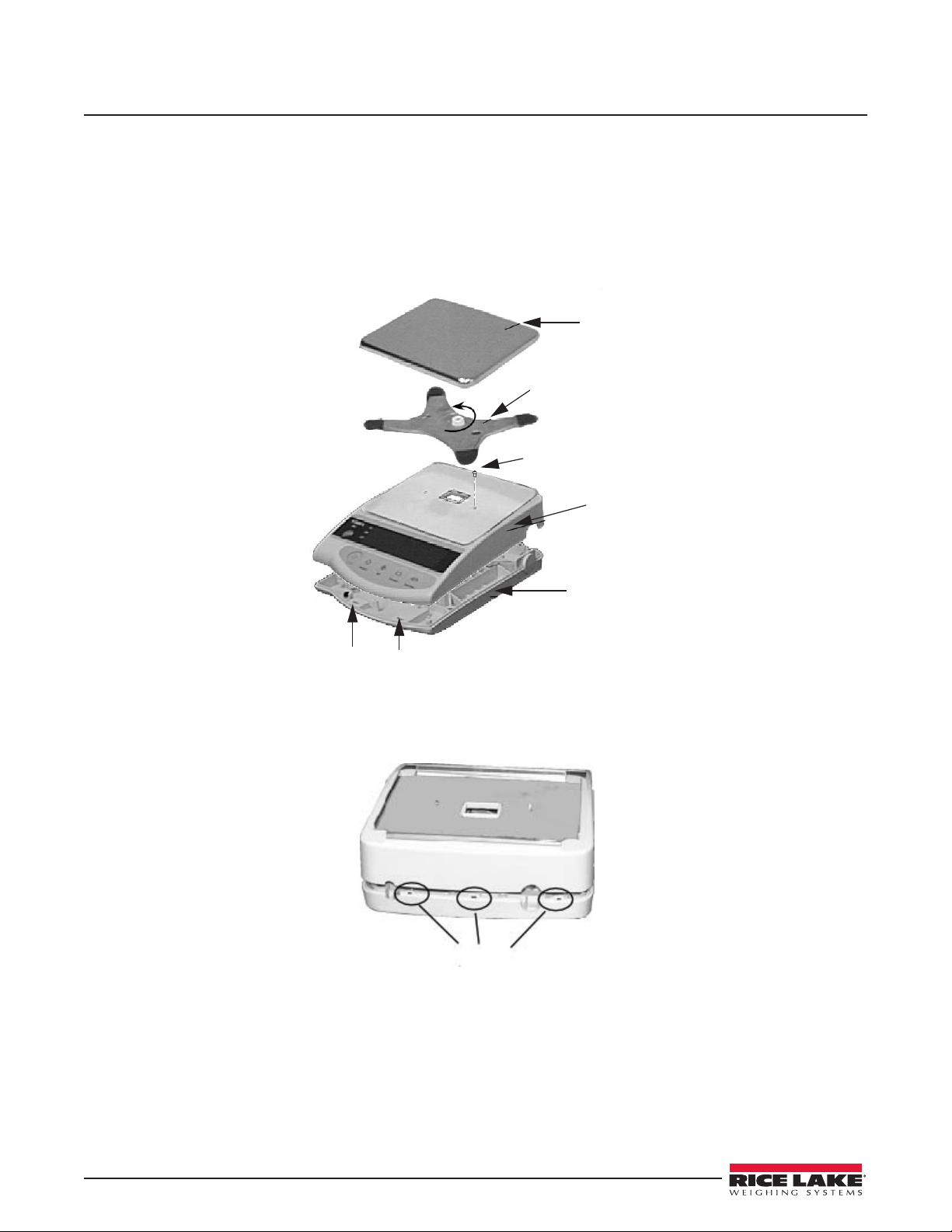
1.1 Remove the Case
1. Pull out the AC adaptor from the scale
2. Remove the pan and pan base.
3. Remove the case-fixing screw.
4. Unfasten the hooks on the bottom front while pulling up the case.
Pan
Pan Base
Case
Fixing
Screw
Case
Hooks
Figure 1-1. Location of Parts
5. Unfasten the hooks on the back and remove the case.
Figure 1-2. Back Hooks Location
Chassis
1 RS-232 Option Card
Page 6
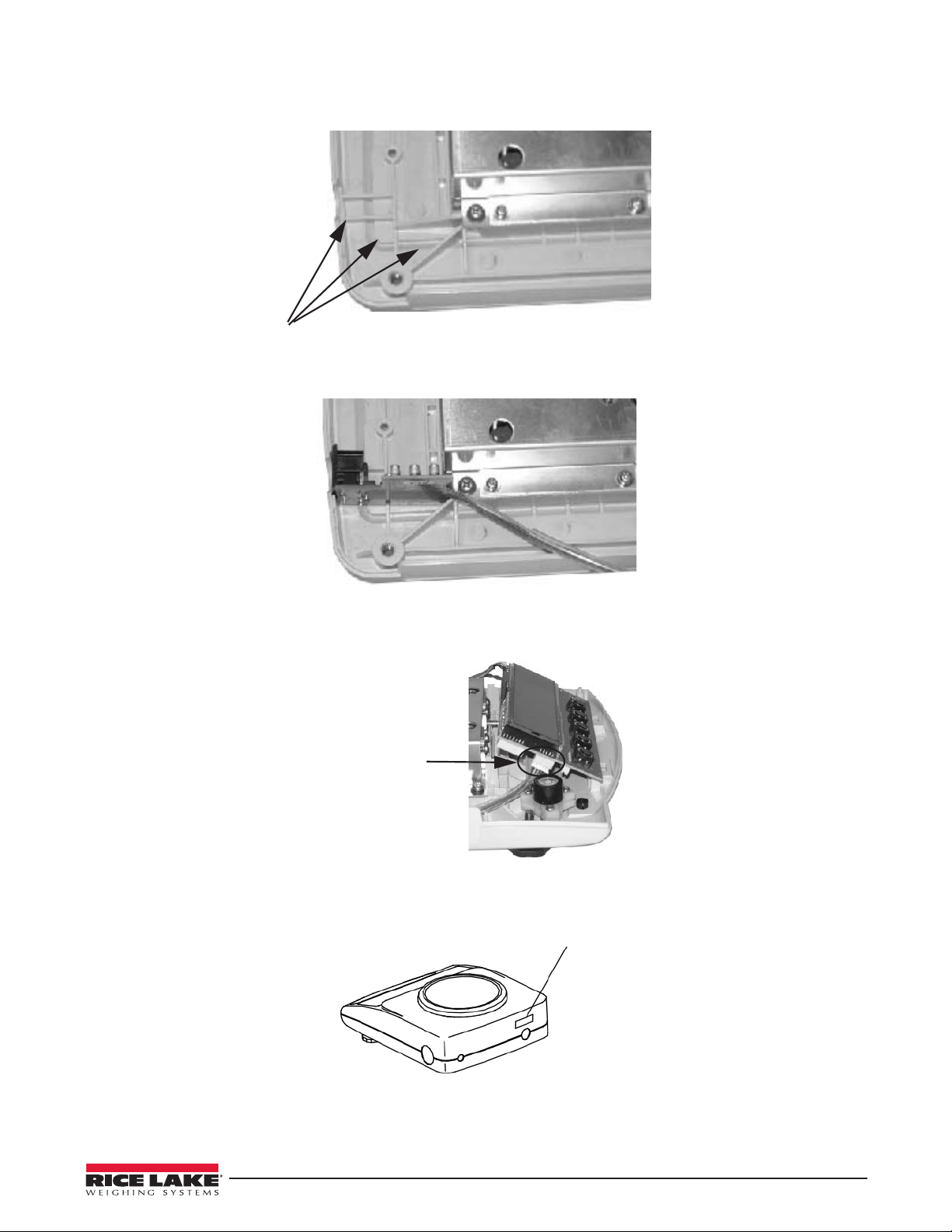
1.2 Install PC Board for Option
1. Install PC board to the chassis. See Figure 1-3 and Figure 1-4.
Insertion Point
Figure 1-3. Insert PC Board
Figure 1-4. Installed Board
2. Insert connectors into SJDP board.
Insert
connectors of
the PC board.
Figure 1-5. Connector to Board Location
3. Cover the case and put RS-232C label on the output terminal.
Label
Figure 1-6. Label Location
Install PC Board for Option 2
Page 7
1.3 Parts List
Part Number Name Amount
21AE002 SJRS Board Assembly 1
3365P Label for RS232C Output 1
FC 059 TCP0556-01-0201 1
Table 1-1. Parts List for RS232 Option
Part Number Name Amount
21AE003 SJLM Board Assembly 1
3339P Label for Relay Contact 1
FC 062 TCP0568-01-0201 1
Table 1-2. Parts List for Relay Contact
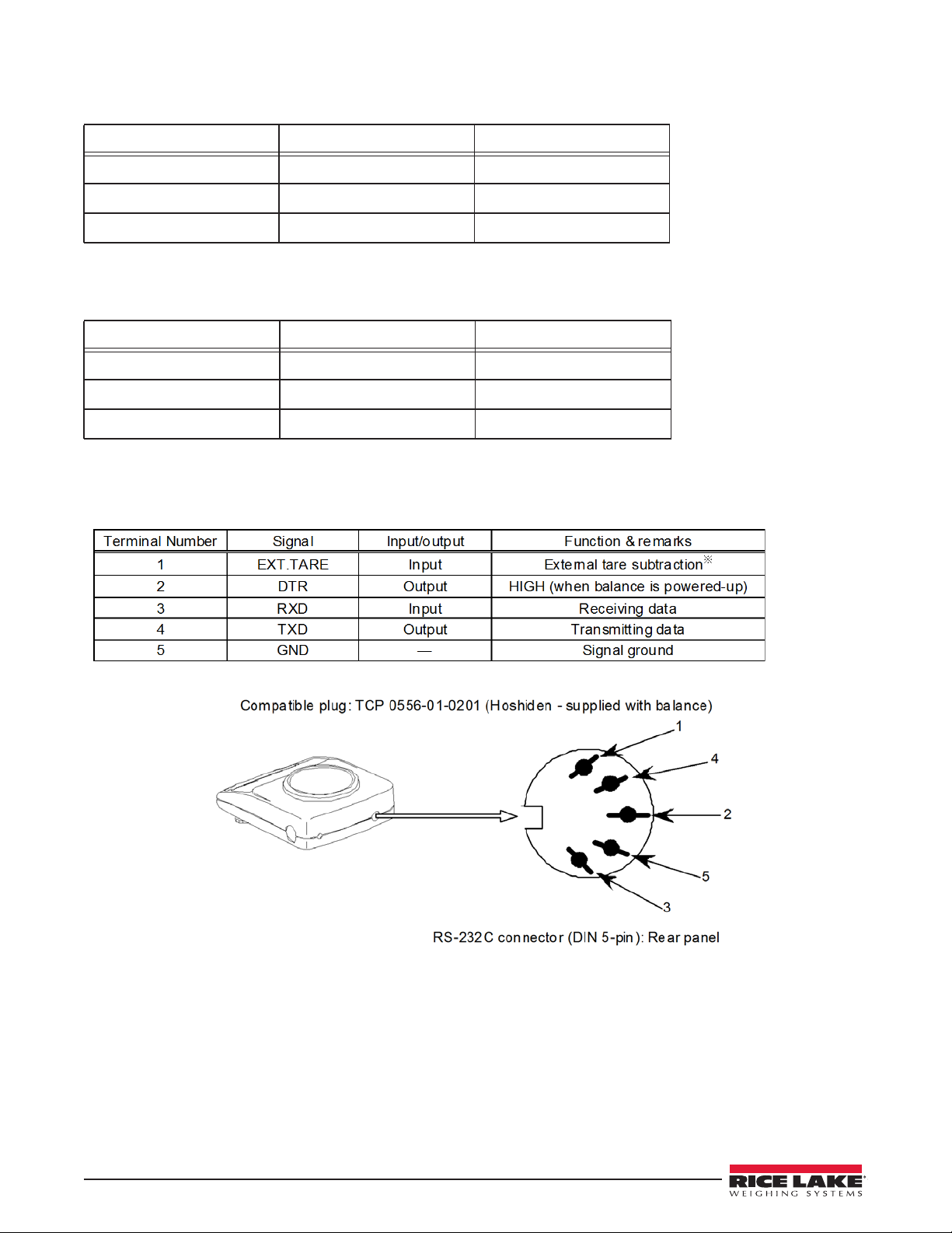
1.4 Terminal Numbers and Functions
Tare subtraction (zero adjustment) is possible by connecting an external tare subtraction input and a signal ground, through
contacts or a transistor switch. When following this procedure, secure a connection time of at least 400 milliseconds. (When
the switch is off, the voltage maximum is 15 V; when the switch is on, the sink current is 20 mA or less.)
NOTE: Before plugging in the connectors, unplug the AC adapter.
3 RS-232 Option Card
Page 8

1.5 Connection between Balances and Personal Computers
IBM-PC/AT
compatible
D-SUB9P
Figure 1-7. Sample connection with an IBM-PC/AT Compatible Computer
Balance
DIN5P
PC9801
D-SUB25P
Balance
DIN5P
Figure 1-8. Sample Connection with PC9801
Connection between Balances and Personal Computers 4
Page 9
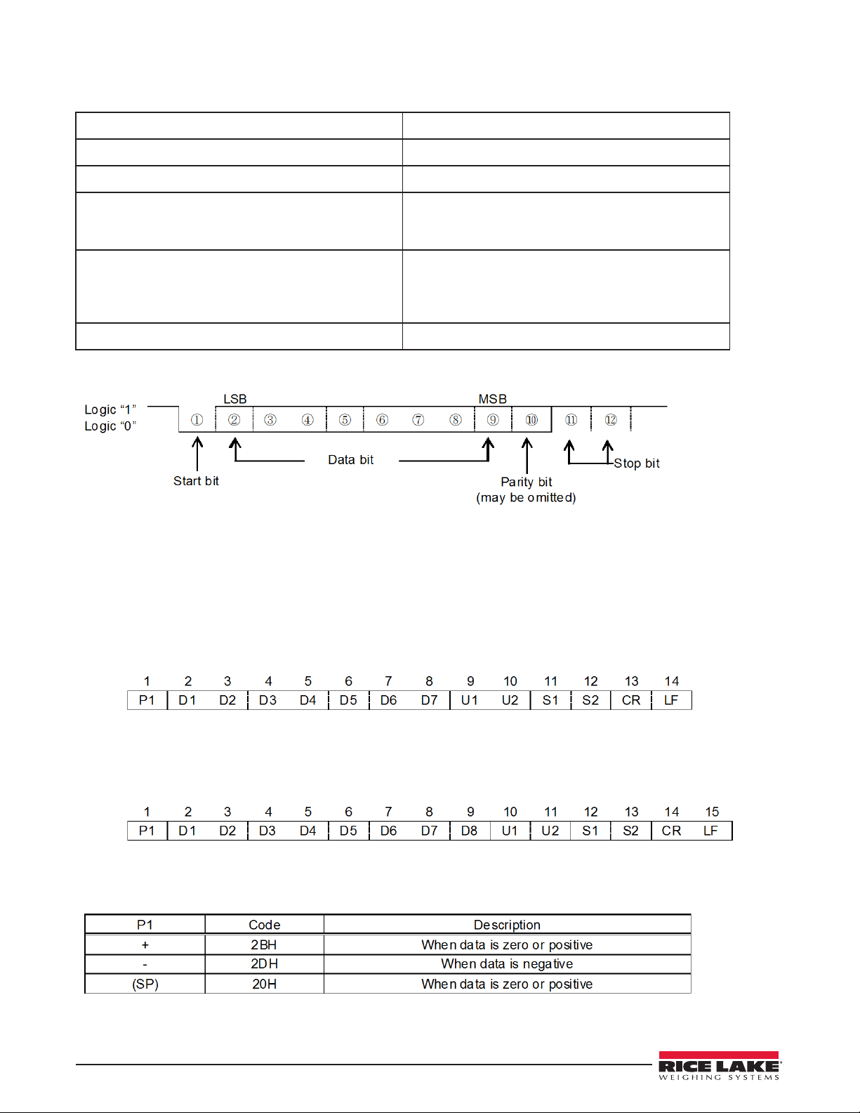
1.6 Interface Specifications
(1) Transmission system Serial transmission with start-stop synchronization
(2) Transmission rates 1200/2400/4800/9600 bps
(3) Transmission codes ASCII codes (8-bit)
(4) Signal levels Compliant with EIA RS-232C
HIGH level (Data logic 0) +5 to +15 V
LOW level (Data logic 1) -5 to -15 V
(5) One-character bit configuration Start bit: 1 bit
Data bit: 8 bits
Parity bit: 0/1 bits
Stop bit: 2 bits
(6) Parity bit none/odd/even
1.7 Output Data
By changing the function settings on the main unit of the balance, users can select either of the following formats: (See Section
“Description of Functions” on page 9)
1.8 Data Format
• Six-digit numeric format
Composed of 14 characters, including the terminators (CR = 0DH, LF = 0AH).
• Seven-digit numeric format
Composed of 15 characters, including the terminators (CR = 0DH, LF = 0AH). A parity bit can also be
appended.
1.9 Polarities (PI: one character)
5 RS-232 Option Card
Page 10

1.10 Numeric Data
Six-digit numeric format: (D1-D7: seven characters)
Seven-digit numeric format: (D1-D8: eight characters)
1.11 Units (U1, U2: two characters)
NOTE: All the codes are ASCII codes.
Numeric Data 6
Page 11
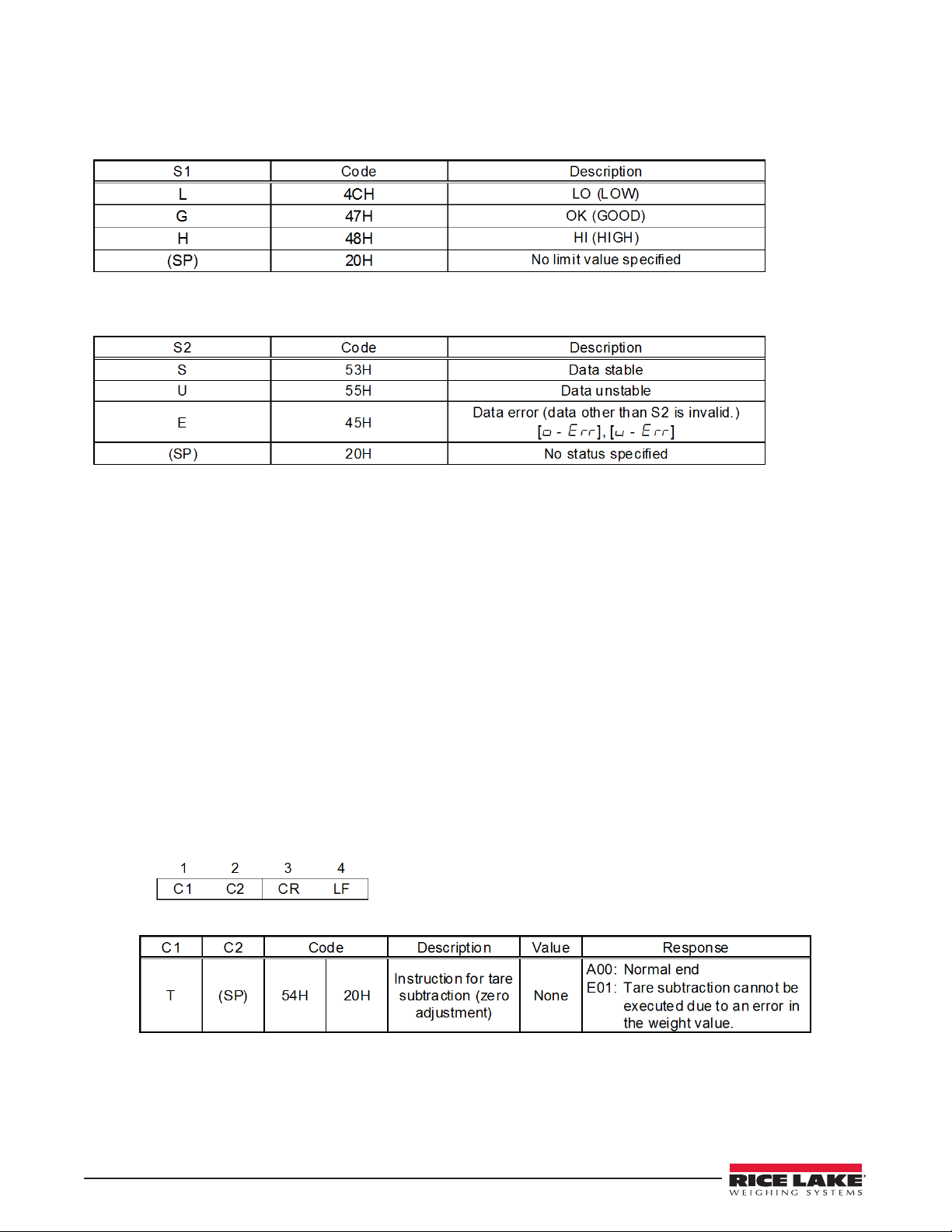
1.12 Result of judgment when operating balance with the limit function
(S1: one character)
Status (S2: one character)
1.13 Input Commands
Users can control the balance remotely by transmitting commands from an external device. Two types of control commands
are available:
• Instruction for tare subtraction
• Setup of output control
1.14 Command Transmission Method
• A command is transmitted to the balance from an external device. Since the data flow (transmission and reception) is
stored by a full-duplex system, commands can be transmitted regardless of their data-transmission timing.
• When the balance has executed the received command, it activates a normal end response or transmits the requested data,
via the transmitting command. If the balance was unable to execute the command or received an erroneous command, it
transmits an error end response. If the balance is working properly, it usually returns a response within a second after it
receives the transmitted command. If the balance receives a transmission while it is conducting a procedure (such as the
setup of a function or a span adjustment), it will transmit a response when the procedure finishes.
• When transmitting more than one command to the balance from a remote device, wait until you have received a
confirmation on the first transmission before transmitting the next.
1.15 Command Format
• Command format
Composed of four characters (ASCII), including the terminators (CR=0DH, LF = 0AH)
• Instruction for tare subtraction (zero adjustment)
7 RS-232 Option Card
Page 12

• Setup of output control
The output controls executed with commands [O0] - [O7] work the same as the output controls executed
through function setup on the main unit of the balance.
The commands [O8] and [O9] are data request commands issued to the balance.
Once any command from [O0] to [O9] is executed, the balance runs that function until another command is
entered. However, if the balance is switched off and on again, the output control is reset to the initial
function (function set value).
1.16 Response Output
• Response output format
Composed of five characters, including the terminators (CR = 0DH; LF = 0AH)
• Types of response outputs
Response Output 8
Page 13

1.17 Description of Functions
9 RS-232 Option Card
Page 14

Description of Functions, continued
1.18 Interface Section
Interface Section 10
Page 15

U.S. 800-472-6703 • Canada/Mexico 800-321-6703 • International 715-234-9171 • Europe +31 (0)26 472 1319
www.ricelake.com www.ricelake.mx www.ricelake.eu www.ricelake.co.in m.ricelake.com
© Rice Lake Weighing Systems November 21, 2014 PN 115148
230 W. Coleman St. • Rice Lake, WI 54868 • USA
 Loading...