

Page 1
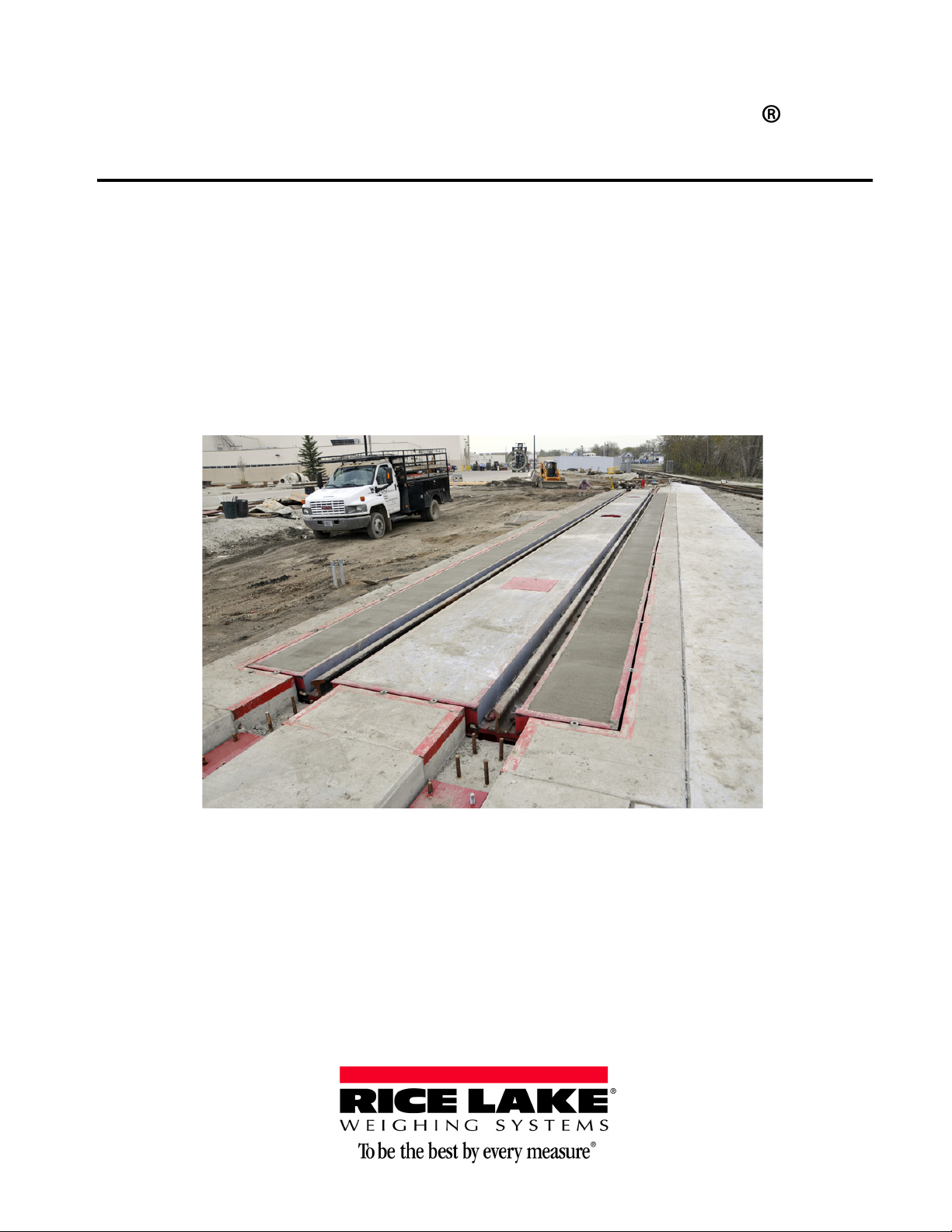
Survivor RT
Pit-Type Track Scale
Installation Manual
110876 Rev A
Page 2

Page 3

Contents
Contents ................................................................................................................................................... i
About This Manual ................................................................................................................................... 1
Safety ....................................................................................................................................................... 1
1.0 Introduction.................................................................................................................................. 2
2.0 Installation ................................................................................................................................... 3
2.1 Weighbridge Installation . . . . . . . . . . . . . . . . . . . . . . . . . . . . . . . . . . . . . . . . . . . . . . . . . . . . . . . . . 3
2.2 Rail Installation . . . . . . . . . . . . . . . . . . . . . . . . . . . . . . . . . . . . . . . . . . . . . . . . . . . . . . . . . . . . . . . . 5
2.3 Grouting . . . . . . . . . . . . . . . . . . . . . . . . . . . . . . . . . . . . . . . . . . . . . . . . . . . . . . . . . . . . . . . . . . . . . . 5
2.4 Concrete Deck. . . . . . . . . . . . . . . . . . . . . . . . . . . . . . . . . . . . . . . . . . . . . . . . . . . . . . . . . . . . . . . . . 6
3.0 Junction Box and Grounding ....................................................................................................... 7
3.1 Load Cells to Junction Box. . . . . . . . . . . . . . . . . . . . . . . . . . . . . . . . . . . . . . . . . . . . . . . . . . . . . . . 7
3.2 Junction Box to Indicator . . . . . . . . . . . . . . . . . . . . . . . . . . . . . . . . . . . . . . . . . . . . . . . . . . . . . . . . 8
3.3 Indicator to Peripherals. . . . . . . . . . . . . . . . . . . . . . . . . . . . . . . . . . . . . . . . . . . . . . . . . . . . . . . . . . 8
3.4 Single-Point Ground Conductor . . . . . . . . . . . . . . . . . . . . . . . . . . . . . . . . . . . . . . . . . . . . . . . . . . . 8
3.5 Junction Box Connections . . . . . . . . . . . . . . . . . . . . . . . . . . . . . . . . . . . . . . . . . . . . . . . . . . . . . . . 8
3.6 Electrical Ground Connections. . . . . . . . . . . . . . . . . . . . . . . . . . . . . . . . . . . . . . . . . . . . . . . . . . . . 8
4.0 Diagrams.................................................................................................................................... 11
Survivor RT Limited Warranty................................................................................................................ 17
For More Information ............................................................................................................................. 18
© Rice Lake Weighing Systems. All rights reserved. Printed in the United States of America.
Specifications subject to change without notice.
May 31, 2013
Page 4

ii Survivor® RT Installation Manual
Page 5
About This Manual
This manual is intended for use by service technicians responsible for installing and servicing 920i pit-type railroad
track scales.
Authorized distributors and their employees can view or download this manual from the Rice Lake
Weighing Systems distributor site at
www.ricelake.com.
Safety
Safety Symbol Definitions:
Indicates an imminently hazardous situation that, if not avoided, will result in death or serious injury.
Indicates a potentially hazardous situation that, if not avoided could result in serious injury or death, and
includes hazards that are exposed when guards are removed.
Indicates a potentially hazardous situation
Indicates information about procedures that, if not observed, could result in damage to equipment or
corruption to and loss of data.
that, if not avoided may result in minor or moderate injury.
General Safety
Do not operate or work on this equipment unless you have read and understand the instructions and
warnings in this manual. Failure to follow the instructions o
death. Contact any Rice Lake Weighing Systems dealer for replacement manuals. Proper care is your
responsibility.
Failure to heed may result in serious injury of death.
Some procedures described in this manual ar
service personnel only
DO NOT allow minors (children) or inexperienced persons to operate this unit.
DO NOT operate without all shields and guards in place.
DO NOT use for purposes other then weight taking.
DO NOT place fingers into slots or possible pinch points.
DO NOT use any load bearing component that is
DO NOT use this product if any of the
DO NOT exceed the rated load limit of the unit.
DO NOT make alterations or modifications to the unit.
DO NOT remove or obscure warning labels.
Keep hands, feet and loose clothing away from moving parts.
components are cracked.
e potentially dangerous. These procedures are to be performed by qualified
worn beyond 5% of the original dimension.
r heed the warnings could result in injury or
1
Page 6

1.0 Introduction
The Survivor
variety of car sizes, the
®
RT is a pit-type track scale and is available as a rail/truck combination scale. Perfect for weighing a
Survivor® RT is capable of weighing rail cars as well as trucks. This scale is ideal for bulk
cement, aggregate, grain, scrap metal, and chemical applications. Cars can be positioned anywhere on the scale,
and a wide range of platform sizes and capacities provide accurate weighments.
Specifications:
• Gross capacity - 200 tons.
• Sectional capacity - 200 tons.
• Platform lengths up to 112’; 49” profile.
• Platform width up to 12’
• Concrete deck - 8”; manhole access.
• Designed for 115 lb. and 132 lb. rail.
• Longitudinal and lateral c
hecking assemblies.
• CSP1-200K compression load cells.
• Conduit hub fittings at each load cell.
• Lightning and surge suppression kit.
• Rail clips for deck.
• Anti-creep angles.
• Copper transient bypass cables.
• In-bridge conduit runs.
• NTEP-certified, CC#00-019, 00-020A1.
• Meets AREMA and Cooper E-80 design specs.
Optional features and accessories include:
• Steel and concrete deck available.
• Approach rail base plates, rail clips, nuts, and washers.
• Anchor bolts for approach rail plates.
• Corrugated sheeting for deck.
• Custom sizes for existing foundations.
• Anchor bolts for load cell and check stands.
•Grain dumps.
The
Survivor® RT is manufactured on-site at Rice Lake Weighing Systems. All railroad track scale production is
conducted in-house under exacting quality control standards. Each railroad track scale is manufactured under the
precise guidelines outlined by ISO 9001 standards. All weighbridge components are sandblasted to SSPC-A-SP6
standards and cleaned to remove grease and oil contaminants. After assembly, all Survivor
®
track scales are
painted with high solids urethane primer, as well as a finish coat of a high solids urethane paint that protects the
weighbridge’s structural integrity and ensures a long life. Non-visible steel surfaces receive an asphalt emulsion
coating to protect from internal moisture.
RT-6010 60’ x 10’ 400,000 lb
RT-6610 66 x 10’ 400,000 lb
RT-7010 70’ x 10’ 400,000 lb
RT-7210 72’ x 10’ 400,000 lb
RT-7510 75’ x 10’ 400,000 lb
RT-8010 80’ x 10’ 400,000 lb
2 Survivor RT Installation Manual
Model Platform Size Capacity
Table 1-1. Survivor RT Series Platform Sizes
Page 7
2.0 Installation
This section describes the assembly procedure for the Survivor
Crush hazard, keep hands, feet and other body parts clear when setting weighbridge modules in place.
Moving parts can crush and cut.
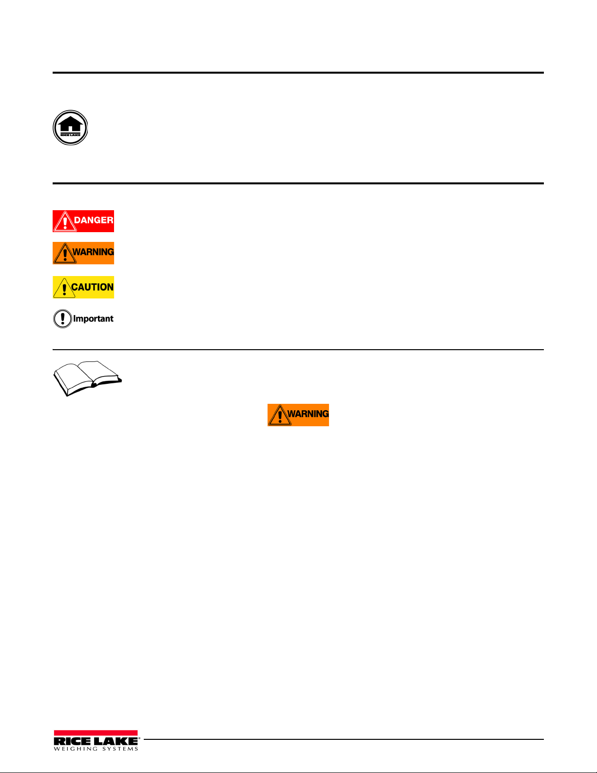
2.1 Weighbridge Installation
1. Set load cell lower base plates in place on
embedded anchors and place necessary
components for each cell at cell location. Refer
to assembly print.
Figure 2-1. Load cell lower base plate
2. Assemble base plates, load cells, and hardware
on lower base plate and set to approximate
height at each location.
®
RT railroad track scale.
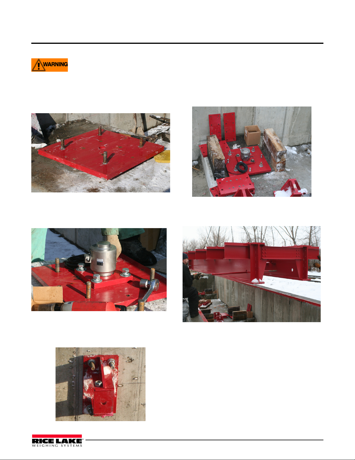
4. Set module on wooden blocking in foundation.
(Place lateral check rods through modules
prior to placing in foundation.)
Figure 2-4. Module on wooden blocking
5. Install side checking rods in weigh bridge prior
to placing the modules.
Figure 2-2. Base plates, load cells, and hardware installed
on lower base plate
3. Set longitudinal checking brackets in place on
embedded hardware as indicated on print.
Figure 2-3. Longitudinal checking bracket
Figure 2-5. Checking rods installation
6. One section at a time, starting with an end, jack
the modules in place and attach shim plate,
bearing cushions, mount top plate, load cell
bearing plate, splice plates, and hardware.
Installation 3
Page 8
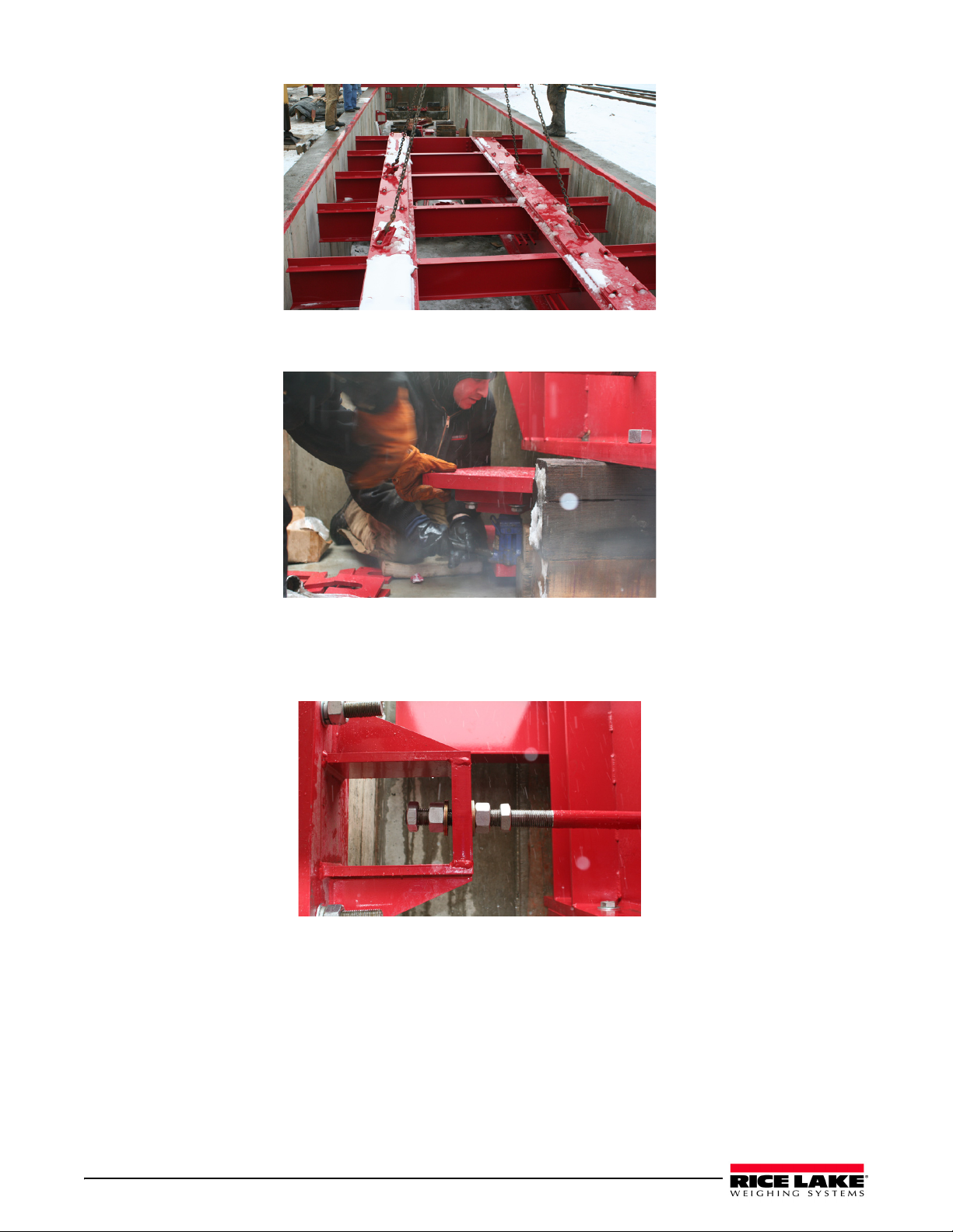
Figure 2-6. Module in place
7. Adjust load cell base plate leveling bolts to proper height and level plates.
Figure 2-7. Load cell base plate adjusting to proper height
8. Continue this process at each section, moving down the scale.
9. Install lateral and longitudinal ch
within
1/2. Weld Spacer Plates (P/N 71860) to weighbridge to secure.
ecking brackets and rods. Set check rods level with a horizontal plane to
Figure 2-8. Check rod
10. Install coping by tack welding coping to outriggers making sure to establish a good ground very near the
area being welded. Use 3/4” nuts between coping and pit wall to allow for deck clearance.
4 Survivor RT Installation Manual
Page 9

2.2 Rail Installation
The following instructions describe the installation of rail sections on the Survivor
1. Cut rail sections using 45
2. Set rail support plates over embedded anchor bolts on the approach foundation.
3. Set weigh rails and approach rails onto the rail support plates.
4. Shim and align rails to match elevation of scale and set the desired grade.
Option: Install jam nuts under approach rail support plates to act as a leveling device.
5. Install rail clips and secure rails in place.
6. Install anti-creep rail anchors.
mitered rail head cuts at the weighrail and approach rail transitions.
Figure 2-9. Mitered rail head cuts location
®
RT.
2.3 Grouting
Prior to grouting, re-check all weighbridge and rail alignment, levels, and elevations.
1. Use a 9000 psi epoxy-type grout under the load cell base plates, and a non-shrink cement-type grout under
the
approach and center section rail support plates.
Do not grout under the longitudinal brackets or side check brackets.
2. After grout has hardened, tighten/torque nuts on all anchor bolts.
Installation 5
Page 10

2.4 Concrete Deck
1. Install deck pan.
Figure 2-10. Deck pan installed
2. Set manhole frames in desired locations and shim to proper height.
Figure 2-11. Manhole frame
3. Install rebar and pour concrete. After the concrete hardens, cut deck pan from within manhole frame.
Figure 2-12. Rebar installed (left) and pouring concrete (right)
6 Survivor RT Installation Manual
Page 11

3.0 Junction Box and Grounding
Electrical conduit is pre-installed at the factory and only needs to be connected between the modules and from the
modules to the junction box (J-box). Following conduit work, load cell cables are routed through each conduit from
the load cells to the J-box. All load cell cabling used for this installation comes in the shipping container. The
layout pattern for the electrical conduit on a three module truck scale installation is shown in Figure 3-2.
Figure 3-1. J-Box Wiring and Conduit
3.1 Load Cells to Junction Box
Each load cell is equipped with 30' of load cell cable, sufficient to reach a centrally-located junction box on
standard scales. A conduit adapter and a 14" section of 3/4" flexible conduit is supplied for both ends of each load
cell cable located at the load cell and at the junction box. Main conduit runs between these 14" flexible end sections
are 3/4" galvanized metal conduit already installed on the deck as shown above.
• Flexible conduit can not come in contact with the ground. Plastic tie wraps are included in the hardware shipping
box and should be used to tie up the flexible conduit.
• If using a single B module, some of the conduit runs are not used. These conduit runs are used when more than one
B modules are installed.
Junction Box and Grounding 7
Page 12

3.2 Junction Box to Indicator
Fifty eight (58) feet of six-wire homerun cable is supplied for wiring the junction box to the indicator. It is run in
3/4" galvanized metal conduit from the junction box to the indicator. Conduit for this purpose is to be obtained
locally. A 30" flexible conduit section and conduit connector is provided where this cable exits the junction box.
Do not run any other electrical cables in or near the conduit to the indicator.
3.3 Indicator to Peripherals
All 3/4" conduit for cabling from the indicator to remote displays and other peripheral devices is to be obtained
locally. Conduit runs may be buried in a trench or secured above ground. Use separate conduit runs for AC power
and DC data lines to avoid interference. As a general guideline, run AC and DC cables in separate trenches if
possible. When DC data cables must run in the same trench as AC power lines, separate cables as much as possible
(preferably more than 34" apart).
3.4 Single-Point Ground Conductor
A bare 10 gauge solid wire is to be run from the scale frame to the grounding lug on the junction box then
underground to the main AC power earth ground. If the DC transient protection board is installed, the ground
conductor should also be connected to the transient protection board’s ground lug.
3.5 Junction Box Connections
Each junction box is large enough to hold the summing board, transient protection devices, packaged desiccant,
and extra load cell cable coiled inside the enclosure. An industrial corrosion inhibitor and desiccant such as the
RLWS Industrial Corrosion Inhibitor (PN 16037) should be added to the junction box enclosure before final
closure.
IA summing card mounted within the junction box is used to make al
are clearly marked as to function.
l cable terminal connections. All terminal pins
3.6 Electrical Ground Connections
Improper grounding systems are often a cause of corrupted data from ground-loop current flows and
costly lightning damage to electronics.
Always strive for a single-point grounding system. Do not drive ground rods at the scale location which
establishes separate earth grounds for the scale. These separate earth grounds will not share the same zero reference
as the existing earth ground for the AC power system. This difference in electrical potential invites ground-loop
current flow between the separate grounds, often corrupting serial data like RS-232 which depends on a stable zero
reference.
In addition, a separate earth ground system at the scale can actually invite lightning
• A minor power line surge should immed
scale with a lower potential than the main ground, the surge may travel out to the scale ground rod, damaging
load cells on its way.
• A nearby lightning ground strike may instantly raise the z
while leaving the scale house ground rod unaffected. That lightning surge will now take the easiest path to the
lower-potential ground—through the scale wiring and back to the scale house ground, possibly damaging the
indicator on its way.
Therefore, the best grounding system for the scale is the same
system. The 120 VAC power source used to power the indicator will be connected to an existing earth grounded
rod system at the scale house or other building where the indicator is located. This should consist of a double
ground rod system of two 5/8" x 8' copper rods driven 8' deep at the service entrance where the local utility
company brings their lines into the building.
The local utility company can test the resistance of the existing ground rods with a clamp-on megohmeter th
measures zero resistance. A reading of 3¾ or less is acceptable as a ground. If the test determines that the
grounding system is inadequate, the utility company can suggest methods to improve the system. It’s crucial that
the scale owner authorize and make the recommended improvements to assure an adequate electrical ground. Do
not connect the scale to the AC power supply until the grounding system is adequate.
iately be shunted to ground. If a separate ground system exists at the
ero potential of a ground rod at the scale location,
grounding system used for the incoming AC power
or power surge damage:
at
8 Survivor RT Installation Manual
Page 13

Be certain each load cell grounding strap is securely connected to the top plate and bottom plate of each load cell
Grounding
Strap
ground before indicator
mount. There should be metal-to-metal contact with no presence of paint or grout. This strap is designed to channel
power surges on the deck around—rather than through—the load cell to ground.
Figure 3-2. Grounding strap on load cell mount.
These, and all, ground connections must be torqued to a specified value and retorqued at regular service intervals.
A thick coating of anti-oxidant grease should be maintained on all ground connections to prevent corrosion.
A separate grounding system conductor must extend uninterrupted
from the main service panel ground to the scale
to protect load cells and scale wiring from lightning and other transient damage. This ground wire conductor must
be an unsheathed #10 copper wire or larger. Run the bare ground wire conductor intact from the AC power ground
rod to the scale in a separate trench. Bring the wire up from the trench near the junction box and attach it to the
ground lug of the junction box. A #10 bare ground wire is run from the ground lug of the junction box to one of the
junction box mounting studs on the scale frame, thus grounding the scale frame to the same single-point ground as
the AC power for the indicator.
.
Figure 3-3. Junction box ground wire connections.
Junction Box and Grounding 9
Page 14

10 Survivor RT Installation Manual
Figure 3-4. Single-point grounding diagram
Page 15

4.0 Diagrams
Diagrams 11
Page 16

12 Survivor RT Installation Manual
Page 17

Diagrams 13
Page 18

14 Survivor RT Installation Manual
Page 19

Diagrams 15
Page 20

16 Survivor RT Installation Manual
Page 21

Survivor RT Limited Warranty
Rice Lake Weighing Systems (RLWS) warrants that all RLWS equipment and systems properly installed by a
Distributor or Original Equipment Manufacturer (OEM) will operate per written specifications as confirmed by the
Distributor/OEM and accepted by RLWS. All systems and components are warranted against defects in materials
and workmanship for two years.
RLWS warrants that the equipment sold hereunder will conform to the current written specifications authorized by
RLWS. RLWS warrants the equipment against faulty workmanship and defective materials. If any equipment fails
to conform to these warranties, RLWS will, at its option, repair or replace such goods returned within the warranty
period subject to the following conditions:
• Upon discovery by Buyer of such nonconformity, RLWS will be given prompt written notice with a
detailed explanation of the alleged deficiencies.
• Individual electronic components returned to RLWS for warranty purposes must be packaged to
prevent electrostatic discharge (ESD) damage in shipment. Packaging requirements are listed in a
publication, Protecting Your Components From Static Damage in Shipment, available from RLWS
Equipment Return Department.
• Examination of such equipment by RLWS confirms that the nonconformity actually exists, and was
not caused by accident, misuse, neglect, alteration, improper installation, improper repair or improper
testing; RLWS shall be the sole judge of all alleged non-conformities.
• Such equipment has not been modified, altered, or changed by any person other than RLWS or its duly
authorized repair agents.
• RLWS will have a reasonable time to repair or replace the defective equipment. Buyer is responsible
for shipping charges both ways.
• In no event will RLWS be responsible for travel time or on-location repairs, including assembly or
disassembly of equipment, nor will RLWS be liable for the cost of any repairs made by others.
THESE WARRANTIES EXCLUDE ALL OTHER WARRANTIES, EXPRESSED OR IMPLIED, INCLUDING WITHOUT
LIMITATION WARRANTIES OF MERCHANTABILITY OR FITNESS FOR A PARTICULAR PURPOSE. NEITHER RLWS
NOR DISTRIBUTOR WILL, IN ANY EVENT, BE LIABLE FOR INCIDENTAL OR CONSEQUENTIAL DAMAGES.
RLWS AND BUYER AGREE THAT RLWS’S SOLE AND EXCLUSIVE LIABILITY HEREUNDER IS LIMITED TO REPAIR
OR REPLACEMENT OF SUCH GOODS. IN ACCEPTING THIS WARRANTY, THE BUYER WAIVES ANY AND ALL OTHER
CLAIMS TO WARRANTY.
SHOULD THE SELLER BE OTHER THAN RLWS, THE BUYER AGREES TO LOOK ONLY TO THE SELLER FOR
WARRANTY CLAIMS.
NO TERMS, CONDITIONS, UNDERSTANDING, OR AGREEMENTS PURPORTING TO MODIFY THE TERMS OF THIS
WARRANTY SHALL HAVE ANY LEGAL EFFECT UNLESS MADE IN WRITING AND SIGNED BY A CORPORATE
OFFICER OF RLWS AND THE BUYER.
© Rice Lake Weighing Systems, Inc. Rice Lake, WI USA. All Rights Reserved.
RICE LAKE WEIGHING SYSTEMS • 230 WEST COLEMAN STREET • RICE LAKE, WISCONSIN 54868 • USA
17
Page 22

For More Information
Web Site
• Frequently Asked Questions (FAQs) at
• http://www.ricelake.com/faqs.aspx
Contact Information
Hours of Operation
Knowledgeable customer service representatives are available 6:30 a.m. - 6:30 p.m. Monday through Friday and 8
a.m. to 12 noon on Saturday. (CST)
Telephone
• Sales/Technical Support 800-472-6703
• Canadian and Mexican Customers 800-321-6703
• International 715-234-9171
Immediate/Emergency Service
For immediate assistance call toll-free 1-800-472-6703 (Canadian and Mexican customers please call
1-800-321-6703). If you are calling after standard business hours and have an urgent scale outage or emergency,
press 1 to reach on-call personnel.
Fax
Fax Number 715-234-6967
Email
• US sales and product information at
• prodinfo@ricelake.com
• International (non-US) sales and product information at
• intlsales@ricelake.com
Mailing Address
Rice Lake Weighing Systems
230 West Coleman Street
Rice Lake, WI 54868 USA
18 Survivor RT Installation Manual
Page 23

Page 24

May 31, 2013 PN 110876 Rev A
 Loading...