

Page 1
®
SURVIVOR OTR
Flattop Truck Scale
Assembly Instructions
53831 Rev D
Page 2

Page 3

Technical training seminars are available through Rice Lake Weighing Systems.
Course descriptions and dates can be viewed at www.ricelake.com/training
or obtained by calling 715-234-9171 and asking for the training department.
Contents
1.0 Introduction.................................................................................................................................. 1
1.1 Safety. . . . . . . . . . . . . . . . . . . . . . . . . . . . . . . . . . . . . . . . . . . . . . . . . . . . . . . . . . . . . . . . . . . . . . . . . 1
2.0 Installation ................................................................................................................................... 2
2.1 Foundation Slab Cure Period . . . . . . . . . . . . . . . . . . . . . . . . . . . . . . . . . . . . . . . . . . . . . . . . . . . . . . . 2
2.2 Assembly Time Estimates. . . . . . . . . . . . . . . . . . . . . . . . . . . . . . . . . . . . . . . . . . . . . . . . . . . . . . . . . . 2
2.3 Recommended Equipment and Tools (Steel Deck) . . . . . . . . . . . . . . . . . . . . . . . . . . . . . . . . . . . . . . . 2
2.4 Lifting and Handling (Steel Deck) . . . . . . . . . . . . . . . . . . . . . . . . . . . . . . . . . . . . . . . . . . . . . . . . . . . . 3
2.5 Temporary Setting Blocks (Steel Deck) . . . . . . . . . . . . . . . . . . . . . . . . . . . . . . . . . . . . . . . . . . . . . . . . 3
2.6 Recommended Equipment and Tools (Concrete Deck) . . . . . . . . . . . . . . . . . . . . . . . . . . . . . . . . . . . 4
2.7 Lifting and Handling (Concrete Deck) . . . . . . . . . . . . . . . . . . . . . . . . . . . . . . . . . . . . . . . . . . . . . . . . . 4
2.8 Temporary Setting Blocks (Concrete Deck) . . . . . . . . . . . . . . . . . . . . . . . . . . . . . . . . . . . . . . . . . . . . 5
3.0 Assemble Deck Modules ............................................................................................................. 6
3.1 Place End Module A . . . . . . . . . . . . . . . . . . . . . . . . . . . . . . . . . . . . . . . . . . . . . . . . . . . . . . . . . . . . . . 7
3.2 Place and Attach Adjoining Modules B and C. . . . . . . . . . . . . . . . . . . . . . . . . . . . . . . . . . . . . . . . . . . 8
3.3 Raise Deck and Level with Approaches . . . . . . . . . . . . . . . . . . . . . . . . . . . . . . . . . . . . . . . . . . . . . . . 9
4.0 Load Cell Mount Installation...................................................................................................... 10
4.1 Install Baseplate and Load Cell. . . . . . . . . . . . . . . . . . . . . . . . . . . . . . . . . . . . . . . . . . . . . . . . . . . . . 10
4.2 Mount Block and Shim (Groutless) Installation (Option 1) . . . . . . . . . . . . . . . . . . . . . . . . . . . . . . . . . 12
4.3 Mount Block and Grout Installation (Option 2). . . . . . . . . . . . . . . . . . . . . . . . . . . . . . . . . . . . . . . . . . 14
5.0 Load Cell Wiring ........................................................................................................................ 16
6.0 Pour, Finish, and Cure Concrete Deck....................................................................................... 19
6.1 Concrete Specifications . . . . . . . . . . . . . . . . . . . . . . . . . . . . . . . . . . . . . . . . . . . . . . . . . . . . . . . . . . 19
6.2 Pour and Finish Concrete Deck . . . . . . . . . . . . . . . . . . . . . . . . . . . . . . . . . . . . . . . . . . . . . . . . . . . . 19
6.3 Moist-Cure Concrete Deck . . . . . . . . . . . . . . . . . . . . . . . . . . . . . . . . . . . . . . . . . . . . . . . . . . . . . . . . 21
7.0 Connecting Electronic Equipment ............................................................................................. 22
7.1 Indicator to Peripherals. . . . . . . . . . . . . . . . . . . . . . . . . . . . . . . . . . . . . . . . . . . . . . . . . . . . . . . . . . . 22
7.2 Single-Point Ground Conductor . . . . . . . . . . . . . . . . . . . . . . . . . . . . . . . . . . . . . . . . . . . . . . . . . . . . 22
7.3 J-box Connections . . . . . . . . . . . . . . . . . . . . . . . . . . . . . . . . . . . . . . . . . . . . . . . . . . . . . . . . . . . . . . 22
7.4 Electrical Ground Connections . . . . . . . . . . . . . . . . . . . . . . . . . . . . . . . . . . . . . . . . . . . . . . . . . . . . . 23
7.5 Installing Transient Protection . . . . . . . . . . . . . . . . . . . . . . . . . . . . . . . . . . . . . . . . . . . . . . . . . . . . . . 25
8.0 Trimming and Calibration.......................................................................................................... 26
8.1 Overview and Equipment Required. . . . . . . . . . . . . . . . . . . . . . . . . . . . . . . . . . . . . . . . . . . . . . . . . . 26
8.2 Trimming Individual Cells . . . . . . . . . . . . . . . . . . . . . . . . . . . . . . . . . . . . . . . . . . . . . . . . . . . . . . . . . 26
8.3 Trimming Paired Sections. . . . . . . . . . . . . . . . . . . . . . . . . . . . . . . . . . . . . . . . . . . . . . . . . . . . . . . . . 28
8.4 Calibration with Test Weights . . . . . . . . . . . . . . . . . . . . . . . . . . . . . . . . . . . . . . . . . . . . . . . . . . . . . . 29
8.5 Serial Tag . . . . . . . . . . . . . . . . . . . . . . . . . . . . . . . . . . . . . . . . . . . . . . . . . . . . . . . . . . . . . . . . . . . . . 29
9.0 Load Cell Replacement.............................................................................................................. 30
© Rice Lake Weighing Systems. All rights reserved. Printed in the United States of America.
Rice Lake Weighing Systems is an ISO 9001 registered company.
Specifications subject to change without notice.
Version 2.1, August 2014
i
Page 4

Rice Lake continually offers web-based video training on a growing selection
of product-related topics at no cost. Visit www.ricelake.com/webinars.
Vehicle Scale Limited Warranty............................................................................................................ 31
For More Information ............................................................................................................................. 32
ii OTR Truck Scale Assembly Instructions
Page 5
1.0 Introduction
Note
DANGER
WARNING
CAUTION
Important
WARNING
This manual is intended for use by technicians responsible for installing and servicing the SURVIVOR® OTR
series truck scale. The OTR truck scale is designed so that on-site installation time is reduced as much as poss ible.
A well-organized, experienced installation crew should be able to install a standard 70' x 11' OTR truck scale in
one day.
This booklet covers the OTR steel deck and concrete deck flattop truck scale installation procedures. Use
these instructions as general installation guidelines unless the engineering drawings furnished with your scale
differ from the instructions in this booklet. Engineering drawings furnished with your scale always take priority
over these general installation guidelines.
Refer to the engineering drawings furnished with the scale for all component numbering sequences.
Authorized distributors and their employees can view or download this manual from the Rice Lake
Weighing Systems distributor site at
Package includes: Assembled weighbridge modules and weighbridge fasteners; load cells; conduit fitting; load
cell mounts with leveling bolts and anchor bolts; copper transient bypass cables at each load cell; conduit for load
cell cable runs; flexible plastic conduit from load cell to metal conduit; conduit fittings from flex conduit to metal
conduit; Poly-carbonate junction box(es); homerun cable to indicator (60' long) and print packages including
foundation drawing (pier or floating slab) and manual.
Package does not include: Approach coping; foundation alignment posts; rebar and mesh for foundatio n; rebar for
deck; concrete; peripherals; freight charges including material handling/crane; transportation permits and fees,
escort(s) charge, and insurance transportation fees.
www.ricelake.com.
1. 1 S af e ty
Safety Symbol Definitions:
Indicates an imminently hazardous situation that, if not avoided, will result in death or serious injury.
Indicates a potentially hazardous situation that, if not avoided, could result in serious injury or death and
includes hazards that are exposed when guards are removed.
Indicates a potentially hazardous situation that, if not avoided, may result in minor or moderate injury.
Indicates information about procedures that, if not observed, could result in damage to equipment or
corruption of and loss of data.
General Safety
Do not operate or work on this equipment unless you have read and understand the instructions and
warnings in this manual. Failure to follow the instructions or heed the warnings could result in injury or
death. Contact Rice Lake Weighing Systems for replacement manuals. Proper care is your
responsibility.
Failure to heed may result in serious injury or death.
DO NOT allow minors (children) or inexperienced persons to operate this unit.
DO NOT operate without all shields and guards in place.
DO NOT use for purposes other than weight measurement.
DO NOT place fingers into slots or possible pinch points.
DO NOT use any load-bearing component that is worn beyond 5% of the original dimension.
DO NOT use this product if any of the components are cracked.
DO NOT exceed the rated load limit of the unit.
DO NOT make alterations or modifications to the unit.
DO NOT remove or obscure warning labels.
Keep hands, feet and loose clothing away from moving parts.
Introduction 1
Page 6

2.0 Installation
The modular sections of the OTR series truck scale are shipped pre-assembled and ready to be placed into position
on temporary setting blocks using a crane.
The deck modules are first connected and positioned on setting blocks. Next, the load cell mounts are installed and
anchored into final position.
Then, run the electrical wiring to the J-box through conduit. The weighbridge is lowered onto the load cell mounts.
All electronic equipment is then connected to finish the installation.
The general assembly order is summarized below:
1. Set deck modules into position on setting blocks.
2. Install load cell mounts in pockets and anchor bolts in baseplates.
3. Run cabling and connect electrical wiring to J-box.
4. Pour, finish, and seal (concrete deck).
5. Connect indicator and peripheral devices.
2.1 Foundation Slab Cure Period
Standard concrete reaches full strength after a 28-day curing period. At seven days, standard concrete reaches
approximately 75% of its maximum strength and can handle moderate loads.
Please refer to ACI318 for additional information regarding concrete curing requirements, and consult your
concrete vendor to discuss curing requirements based upon the mix used specifically for your site. Loading of a
slab before it reaches 75% of its maximum strength may cause permanent structural damage.
2.2 Assembly Time Estimates
When scheduling installation for a typical three-module, 70' truck scale, plan for a two-hour minimum crane rental
to place the modules into position. A two-man crew, aided by a crane operator, can unload modules from the truck
and place them into position in approximately 1 hour.
Mount and load cell installation will require approximately 3 – 4 hours. Electrical wiring is run through conduit
and can be done in approximately 2 – 3 hours.
For concrete deck scales, a concrete crew of three or four can normally pour, finish, and seal-cure the concrete deck
surface of a 70' scale in 2 – 3 hours. Final wiring connections can normally be completed the same day while the
concrete is curing. These estimated times may vary.
2.3 Recommended Equipment and Tools (Steel Deck)
• Crane with a minimum 8000 lb.* capacity
• Four chains or cables (8' minimum length each) with hooks or clevises
• 3/4" rotary hammer drill
• 3/4" x 24" masonry carbide bit
• One low-profile 4-ton bottle jack
• 5 1/2" setting blocks
• Various thickness shims to level scale
• Torque wrench to 100 ft-lb
• Socket wrenches to 1 1/2" (drive compatible with torque wrench)
• Box end wrenches to 1 1/4"
• Open end wrench set (7/16" – 1 1/4")
• 4' bubble level
• Small torpedo level
• Hammers, maul, pry bar
• Hand tools for pulling and connecting electrical wiring
* Typical single module weight of 70' x 11', three-module truck scale.
2 OTR Truck Scale Assembly Instructions
Page 7
2.4 Lifting and Handling (Steel Deck)
DANGER
Note
7.5"
5 1/2"
12 1/4"
17 3/4"
1/4"
18"
Note
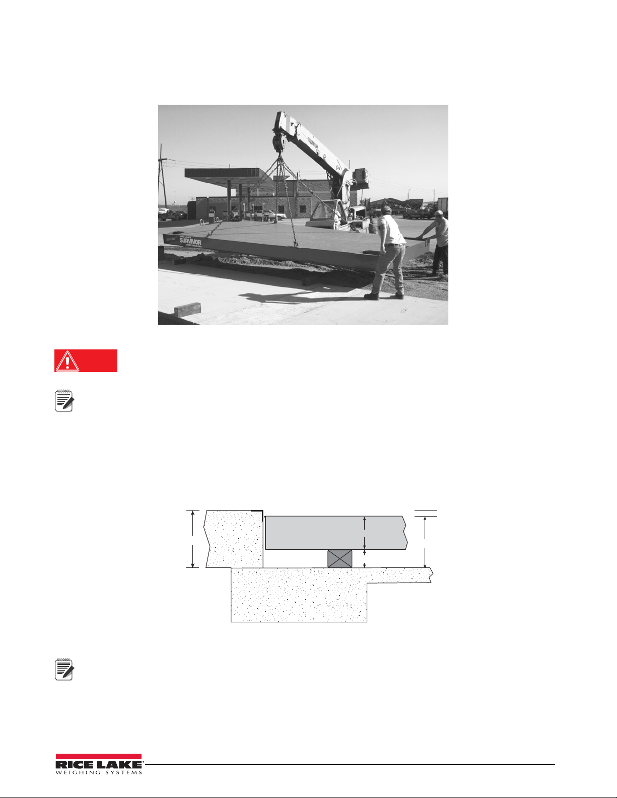
Deck modules are lifted (see Figure 2-1) using four chains or cables attached to the four lift lu gs mounted on the
top of the weighbridge. The lift lugs provide balanced lifting of the modules.
Figure 2-1. Lifting Deck Modules (Steel Deck)
Loads may disengage from crane scale hook and shackle or lifting eye if proper procedures are not
followed. A falling load may cause serious injury or death.
Never lift more than the crane scale’s assigned Working Load Limit (WLL) rating.
A set of lifting lugs are provided with the scale and shipped on the last module loaded on the truck at the
factory.
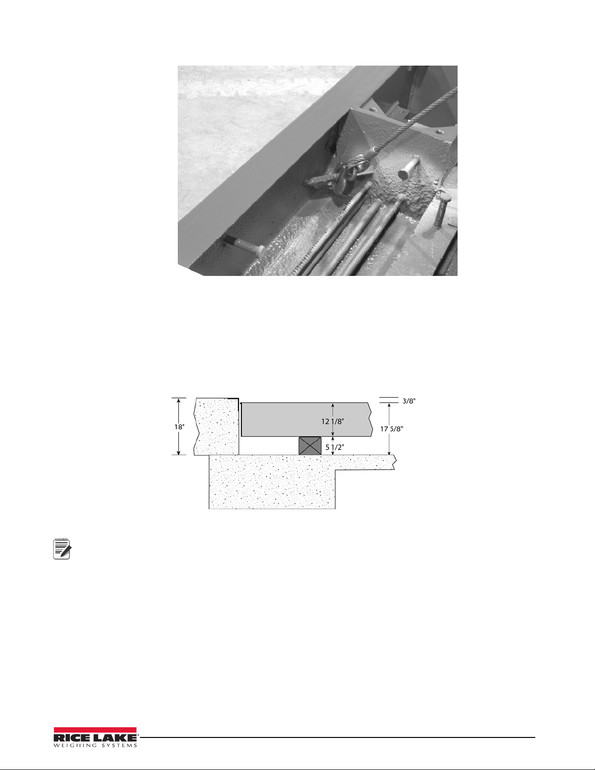
2.5 Temporary Setting Blocks (Steel Deck)
When the deck is level with the approaches, the finished scale has 5 3/4" clearance between the bottom of the
weighbridge and the concrete foundation. Most installers use setting blocks that are approximately
5 1/2" high for the initial placement and connecting of the deck modules. Shims are used to level the scale and raise
it flush with the approach bulkhead. Setting blocks are only used in the corners of the modules where the load cell
mounts are installed. The corners that do not have load cell mount locations do not require setting blocks.
Figure 2-2. Setting Block Measurements (Steel Deck)
Figure shown for 18" foundation profile.
When placing modules on setting blocks, place blocks in locations close to, but not at, the pocket (to allow
room for mount).
Installation 3
Page 8
2.6 Recommended Equipment and Tools (Concrete Deck)
DANGER
• Crane with a minimum 7000 lb* capacity
• Four chains or cables (8' minimum length each) with hooks or clevises
• 3/4" rotary hammer drill
• 3/4" x 24" masonry carbide bit
• One low-profile 4-ton bottle jack (20-ton jack required after concrete pour)
• 5 1/2" setting blocks
• Various thickness shims to level scale
• Torque wrench to 100 ft-lb
• Socket wrenches to 1 1/2" (drive compatible with torque wrench)
• Box end wrenches to 1 1/4"
• Open end wrench set (7/16" – 1 1/4")
• 4' bubble level
• Small torpedo level
• Hammers, maul, pry bar
• Hand tools for pulling and connecting electrical wiring
• Concrete vibrator (optional)
• Concrete screed board, bull float, hand trowels, edger, and broom
• Long-handled paint roller or spray gun for applying epoxy curing agent
* Typical single module weight of 70' x 11', three-module truck scale.
2.7 L
ifting and Handling (Concrete Deck)
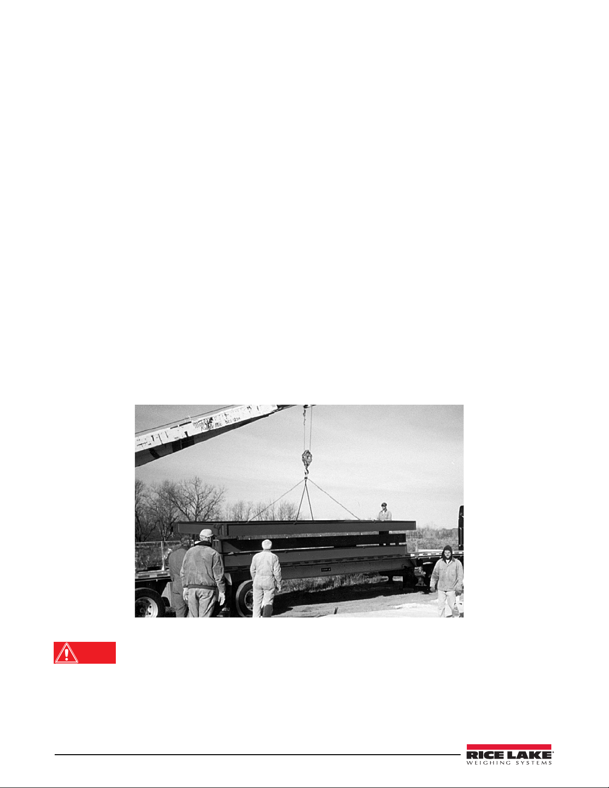
Concrete deck modules are lifted (see Figure 2-3) using four chains or cables attached to the four gussets mounted
on the inside of the main beams. The gussets provide balanced lifting of the modules.
Figure 2-3. Lifting Deck Modules (Concrete Deck)
Loads may disengage from crane scale hook and shackle or lifting eye if proper procedures are not
followed. A falling load may cause serious injury or death.
Never lift more than the crane scale’s assigned Working Load Limit (WLL) rating.
4 OTR Truck Scale Assembly Instructions
Page 9
Following module final positioning, the gussets are no longer needed and are covered by the final concrete pour.
Note
Figure 2-4. Lifting Gusset
2.8 Tempo
rary Setting Blocks (Concrete Deck)
When the deck is level with the approaches, the finished scale has 5 7/8" clearance between the bottom of the
weighbridge and the concrete foundation. Most installers use setting blocks that are approximately 5 1/2" high
for the initial placement and connecting of the deck modules. Shims are used to level the scale and raise it flush
with the approach bulkhead. Setting blocks are only used in the corners of the modules where the load cell mounts
are installed. The corners that do not have load cell mount locations do not require setting blocks.
Figure 2-5. Setting Block Measurements (Concrete Deck).
Figure 2-5 shown for 18" foundation profile.
When placing modules on setting blocks, place blocks in locations close to but not at pocket (to allow room for
mount).
Installation 5
Page 10
3.0 Assemble Deck Modules
Note
BA C
d d
Section dd
Module Support Pin
Pin Connection Receptacle
Concrete
Approach
Concrete
Approach
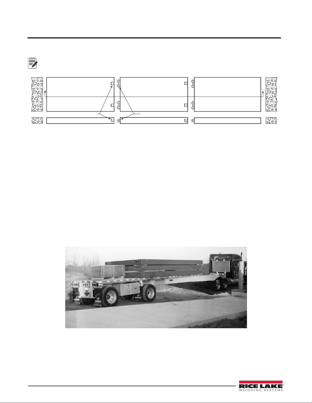
Deck modules are designated as A, B or C (see Figure 3-1). All two-module scales have an A and C module, while
longer scales with more than two modules have one or more B modules.
The modules are typically marked as A, B, or C on the end of each module for identification during placement
and assembly.
Figure 3-1. OTR Deck Modules
A Module
An A module is an end module and is the first to be placed on setting blocks. The left end is a straight end which is
positioned next to the vertical wall of the concrete approach (see Figure 3-1). The right end of the A modu le
contains two pin-connection receptacles that are used to accept the two module-support pins located on the B
module.
B Module
The B module is a center module and is similar in design to the A module, with the exception that it has two
module-support pins on the left end and two pin-connection receptacles on the right end (see Figure 3-1). The tw o
module-support pins of module B are inserted into the two pin-connection receptacles of module A. Also, the
pin-connection receptacles of module B accept the module-support pins from another B module or a C module.
C Module
The C module is also an end module and is the last one placed on setting blocks (see Figure 3-1). The two
module-support pins are designed to attach to either an A module for a two-module installation or to a B module
for an installation that has more than two modules. The opposite end of the C module is a straight end and is
positioned next to the vertical wall of the concrete approach.
Figure 3-2. Weigh Modules Ready for Removal and Installa tion
Modules have been stacked on the truck for shipping in the order that they are installed (see Figure 3-2). The A
module is the top module, followed by any B modules, and the C module is the bottom module.
6 OTR Truck Scale Assembly Instructions
Page 11
3.1 Place End Module A
Note
Note
Note
Before lifting the A module from the truck, place four 5 1/2" temporary setting blocks on the concrete fo undation at
each of the four corners. Also re-measure the overall distance between approaches. The OTR series is undersized 1
1/2". When installed in a 70' opening, there will be a 3/4" gap between the approaches and the scale. Minor
adjustments can be made when setting the first module to equally space the scale between approaches.
Depending on foundation and clean out requirements, a different size of setting blocks may be needed.
Assembly instruction references an 18" approach profile for a 5 3/4" clean out. Adjust as needed for your
application needs.
Figure 3-3. Module Positioned on Temporary Setting Blocks
Position each setting block so that it does not interfere with installation of the load cell mounts.
Place module A with the straight end 3/4" from the concrete bulkhead. With 5 1/2" setting blocks, the deck surface
is 1/4"-3/8" from the top of the concrete approach. Square this module with the approach and check that the
side-to-side dimensions are the same.
Figure 3-4. Setting Modules in Place
Before installing the B module, check that no debris has fallen into the two pin-connection receptacles.
Assemble Deck Modules 7
Page 12
3.2 Place and Attach Adjoining Modules B and C
Note
In a scale with more than two modules, the next module is a B module (see Figure 3-5); if the scale has only two
modules, it is a C module. Place two 5 1/2" setting blocks at the corners opposite of the module support pins (load
cell mount locations) to support the B module.
Figure 3-5. Module B Installation
Place the B module so that the module-support pins engage with the pin-connection receptacles (see Figure 3-6) of
module A and the opposite end rests on the two setting blocks.
Figure 3-6. Pin and Receptacle Interface
If the pins do not seat squarely in the receptacles, raise the module slightly, and then reset the module again.
When the B module is in place, remove the cables or chains from the module and install any other B modules or the
C module in a similar manner.
The C module is installed in the same way that the B module was installed. The end of the C module should be
approximately 3/4" from the approach bulkhead.
The weigh module setup is now complete and the scale is ready to be leveled.
8 OTR Truck Scale Assembly Instructions
Page 13

3.3 Raise Deck and Level with Approaches
Note
Use the following steps to raise and level the weigh modules with the concrete approach:
1. Beginning at the approach (left) end of module A, raise the scale deck using low-profile hydraulic jacks.
Add shims on the setting blocks until the deck surface is level with the approach. Move to the opposite end
of module A, and raise and level this end.
Figure 3-7. Leveling Deck with Approaches
2. When all four corners of the A module are leveled, check the module for being square with the approach
and that it has a 3/4" end clearance from the concrete bulkhead.
3. Move to the B module and continue leveling the weighbridge by leveling the load cell mount end of the B
module.
4. Raise, level, and shim any othe r B modules if they are installed. When the B module or modules are done,
continue by leveling the C module in the same manner.
Figure 3-8. Check Weighbridge for Level
5. When all modules are leveled and shimmed, check the edge alignment with a stringline or a level along
one side of the main beam. Also, check the module support pins to see if they are firmly seated in the
pin-connection receptacles
.
6. As a final check, make sure that the weighbridge end clearance is within specified requirements. The deck
is now at its final position and ready for load cell mount installation.
If transit is used to level scale, the procedure in Section 3.3 on page 9 could be accomplished while installing
shims in Section 3 of the manual.
Assemble Deck Modules 9
Page 14

4.0 Load Cell Mount Installation
Load cell mount components (baseplate, mount blocks, anchor bolts, link, load cell, flexcable, and upper mount
blocks) are shipped in the hardware box and need to be assembled while in the load cell pocket. Remove the
printed load cell Certificate of Conformance (CC) forms (included with load cells) and store them in a safe place
for future reference.
The following sections contain step-by-step instructions on mount installation, including the baseplate, load cells,
upper mount blocks (shim and grout), ground straps, and anchor bo lts.
4.1 Install Baseplate and Load Cell
Use the following steps for installing the mount baseplate and load cell in the load cell mount pockets:
1. Remove load cell mount components from the packing box and position one set at each mount location.
Figure 4-1. B aseplate
2. Working with the baseplate first, lower baseplate through pocket opening and onto concrete foundation.
3. Remove cover plate from 90° fitting included with conduit assembly and insert load cell cable through
fitting sticking through area where plate was (see Figure 4-2).
Figure 4-2. Inserting Load Cell Cable Through 90° Fitting
4. Thread 90° fitting to the load cell, making sure the cable does not twist. Insert cable through second half of
fitting and conduit, then re-install cover plate to 90° fitting. This method prevents connections from being
twisted off inside the load cell.
10 OTR Truck Scale Assembly Instructions
Page 15

Figure 4-3. Installing 90° Fitting to Load Cell
5. Place the load cell link over the end of the cell and install load cell/link assembly onto the top of the
baseplate.
6. Apply anti-seize compound to threads of load cell bolts before installing. Torque load cell bolts 50 – 75
ft-lb.
Figure 4-4. Top View of Load Cell Access Area
7. Position flexcable so that a loop can be made in it and the end can be attached to the rigid conduit.
Load Cell Mount Installation 11
Page 16

4.2 Mount Block and Shim (Groutless) Installation (Option 1)
Note
Upper mount
block
Shim
Note
Note
Use the following procedure for installing mount blocks and shims for leveling.
RLWS has a shim plate (PN 67292) available to level scale. Do not exceed over 3/4" of shims combined. If more
is necessary, contact RLWS for other options.
Figure 4-5. Sample Shim Dimensions
1. Apply anti-seize compound to threads of mount block bolts.
2. Install one bolt through welded block into upper mount block.
3. Add or remove shims until radius of block comes in contact with rocker link radius.
12 OTR Truck Scale Assembly Instructions
Figure 4-6. Shim Installation (Option 1)
4. Install second bolt assembly through blocks and shims, then torque to 55 ft-lb. Repeat process on a ll load
cell pockets.
Position the slotted end of shim towards shorter end of load cell pocket. This allows more room to work when
adding or removing shims.
5. Recheck the link for any binding or misalignment and ensure that the link is plumb in respect to the upper
blocks. Also, check that the link is centered between the side of the link and the upper blocks.
If needed, tap the edge of the baseplate with a hammer to make minor adjustments in alignment.
Page 17

Figure 4-7. Recheck Link for Binding
6. Jack the weigh module and remove the setting blocks.
7. Slowly lower the weigh module until it rests on the load cell links.
8. Use an industrial hammer drill to drill a 3/4" hole into the concrete at least 6" deep on one side of the
baseplate (see Figure 4-8).
Figure 4-8. Drill Anchor Bolt Holes
9. Drill a second anchor bolt hole on the opposite side of the baseplate.
10. Each mount requires two anchor bolts to prevent longitudinal motion of the baseplate. Anchor bolts
(7" x 3/4") with expansion heads are supplied with the scale (see Figure 4-9).
Figure 4-9. Anchor Bolts with Washers
11. Insert bolts into holes drilled in the foundation.
Load Cell Mount Installation 13
Page 18

12. Install one washer and one nut on each anchor bolt. Place a driver pipe on top of the bolt and use the long
Ground strap
Note
punch to seat the anchor bolts against the base p late . Tighten anchor bolt nuts.
Figure 4-10. Seating Anchor Bolts on Baseplate
13. Attach one end of the ground strap to the upper block.
14. Insert a bolt through the wire terminal on the loose end and thread the bolt into the hole on the baseplate.
Tighten the bolt securely with a wrench.
Figure 4-11. Ground Strap
4.3 Mount Block and Grout Installation (Option 2)
Use the following steps to install mount blocks and baseplate grout:
1. Adjust leveling bolts until radius of block comes in contact with rocker link radius.
2. Jack the weigh module and remove setting blocks.
3. Slowly lower the weigh module until it rests on the load cell links.
After the weigh module is lowered into final position, check each load cell mount assembly to ensure that the
link is plumb and that there is no binding or misalignment.
4. Use an industrial hammer drill (see Figure 4-8 13) to drill a 3/4" hole into the concrete at least 6" deep on
one side of the mount frame.
5. Drill a second anchor bolt hole on the opposite side of the mount frame.
6. Each mount requires two anchor bolts to prevent longitudinal motion of the baseplate. Anchor bolts (7" x
3/4") with expansion heads are supplied with the scale (see Figure 4-9 13).
14 OTR Truck Scale Assembly Instructions
Page 19

7. Insert bolts into holes drilled in foundation.
Note
8. Install one washer and one nut on each anchor bolt. Place a driver pipe on top of the anchor bolt and use the
long punch to seat anchor bolts against baseplate (see Figure 4-10 14).
Do not apply excessive force to the anchor bolts-- bending of the baseplate could occur.
When installing anchor bolts, make sure that there is adequate bolt length to extend into the concrete
foundation.
9. Attach one end of the ground strap to the upper block.
10. Insert a bolt through the wire terminal on the loose end and thread the bolt into the hole on the baseplate.
Tighten the bolt securely with a wrench (see Figure 4-11 14).
11. Erect temporary wood en form s around each baseplate and pour 9000 PSI, non-shrinking, epoxy or cement
grout into the forms beneath the baseplate (see Figure 4-12). A funnel with a long tube can be used to pour
grout into the forms while working from above the access hole.
Figure 4-12. Temporary Wooden Forms Around Baseplate
12. After pouring the grout, tap the form several times with a hammer to remove any air voids beneath the
baseplate; it must have even support from continuous grout contact.
13. Remove the temporary wooden forms when the grout is set (see Figure 4-13). Grout should be allowed to
set for at least 24 hours before removing the wooden forms.
Figure 4-13. Completed Baseplate Grouting
14. After grout has hardened, tighten anchor bolt nuts.
Load Cell Mount Installation 15
Page 20

5.0 Load Cell Wiring
Load Cell
Cable to
Connector
Pocket 1 Conduit
Pocket 8 Conduit
Pockets 1, 2, 3, 4
Conduit runs to J-Box
Pocket 5 Conduit
Module A Module B
Pocket 3 Conduit
1
8
2
7
SI - Green
SI - White
EX - Red
EX - Black
SHD - Shield
+
+
-
+SI
-SI
+EX
-EX
SHD
+SI
-SI
+EX
-EX
SHD
+SI
-SI
+EX
-EX
SHD
+SI
-SI
+EX
-EX
SHD
J3
J4
J7
J8
J6
J5
J2
J1
+SI
-SI
+EX
-EX
SHD
+SI
-SI
+EX
-EX
SHD
+SI
-SI
+EX
-EX
SHD
+SI
-SI
+EX
-EX
SHD
Load Cell #1 Load Cell #3
Load Cell #8 Load Cell #6
Load Cell #2 Load Cell #4
Load Cell #7 Load Cell #5
+SI
-SI
+EX
-EX
SHD
-SEN
+SEN
SHD - Shield
+SI
-SI
+EX
-EX
SHD
-SEN
+SEN
Indicator/J10
Expansion/J9
Cable to Indicator
SI - Green+
SI - White-
EX - Red+
EX - Black-
SEN - Yellow-
SEN - Blue+
Pocket 4 Conduit
Pocket 6 Conduit
6
3
Pocket 4 Conduit
Pocket 5 Conduit
5
4
Module C
Electrical conduit is pre-installed at the factory and only needs to be connected between the modules and from the
modules to the junction box (J-box). Following conduit work, load cell cables are routed through each conduit from
the load cells to the J-box. All load cell cabling used for this installation comes in the shipping container. The
layout pattern for the electrical conduit on a three module truck scale installation is shown in Figure 5-1.
Figure 5-1. J-Box Wiring and Conduit Runs for a Four Section/Three Module Scale
16 OTR Truck Scale Assembly Instructions
Page 21

Pocket 1 Conduit
Conduit runs to J-Box
Pocket 3 Conduit
Pocket Conduit for J-Box 2
cable to Expansion Slot in J-Box 1
Pocket 5 Conduit
Load Cell
Cable to
Connector
Pocket 9 and 10
Conduit runs to J-Box
SI - Green
SI - White
EX - Red
EX - Black
SHD - Shield
+
-
+
-
+SI
-SI
+EX
-EX
SHD
+SI
-SI
+EX
-EX
SHD
+SI
-SI
+EX
-EX
SHD
+SI
-SI
+EX
-EX
SHD
J3
J4
J7
J8
J6
J5
J2
J1
+SI
-SI
+EX
-EX
SHD
+SI
-SI
+EX
-EX
SHD
+SI
-SI
+EX
-EX
SHD
+SI
-SI
+EX
-EX
SHD
Load Cell #1
Load Cell #2
Load Cell #9
Load Cell #3
Load Cell #10
Load Cell #8
+SI
-SI
+EX
-EX
SHD
-SEN
+SEN
SHD - Shield
+SI
-SI
+EX
-EX
SHD
-SEN
+SEN
Indicator/J10
Expansion/J9
Cable from J-Box 2
SI - Green+
SI - White-
EX - Red+
EX - Black-
SEN - Yellow-
SEN - Blue+
Pocket 10 Conduit
Module C Module B Module AModule D
Pocket 4 Conduit
3
8
2
1
10
9
5
4
Section 1B
Section 1A
Section 2B
Section 2A
Section 3B
Section 3A
Section 4B
Section 4A
Section 5B
Section 5A
6
7
Pocket 5 and 6 Conduit
J-Box 2
J-Box 1
Load Cell
Cable to
Connector
SI - Green
SI - White
EX - Red
EX - Black
SHD - Shield
+
+
-
+SI
-SI
+EX
-EX
SHD
+SI
-SI
+EX
-EX
SHD
J3
J4
J2
J1
+SI
-SI
+EX
-EX
SHD
+SI
-SI
+EX
-EX
SHD
Load Cell #4 Load Cell #7
Load Cell #5 Load Cell #6
+SI
-SI
+EX
-EX
SHD
-SEN
+SEN
SHD - Shield
+SI
-SI
+EX
-EX
SHD
-SEN
+SEN
Indicator/J10
Expansion/J9
Cable to J-Box 1
SI - Green+
SI - White-
EX - Red+
EX - Black-
SEN - Yellow-
SEN - Blue+
Detail A
Detail B
SHD - Shield
Cable to Indicator
SI - Green+
SI - White-
EX - Red+
EX - Black-
SEN - Yellow-
SEN - Blue+
J-Box 1 - Detail A
J-Box 2 - Detail B
Figure 5-2. J-Box Wiring and Conduit Runs for a Five Section/Four Module Scale
Load Cell Wiring 17
Page 22

Before the weigh module wiring can be completed, all load cell cables have to be routed through the conduit
Note
beginning at the load cell outlet. Use the following steps to route load cell cables through conduit to the J-box:
1. Before routing load cell cables, mark each load cell cable at the end to help identify each load cell.
2. Carefully make a loop in the flex conduit and position the end of the flex conduit close to the end of the
rigid conduit.
Figure 5-3. Load Cell Pocket Conduit Installed
3. Working from the J-box end, insert a fish tape or similar tool and pull each load cell cable through the rigid
conduit until all excess cable is taken in. When all load cell cable is pulled through, insert end of the flex
conduit over the end of the rigid conduit and tighten fitting.
4. Wire each load cell to the J-box terminal strip in accordance with the wiring code contained in the
Certificate of Conformance.
Load cell cable may be cut for best fit. Standard warranty will not be affected.
Figure 5-4. J-box Pocket
Figure 5-5. Conduit Connection Between Deck Modules
18 OTR Truck Scale Assembly Instructions
Page 23

6.0 Pour, Finish, and Cure Concrete Deck
Once the load cell cable is installed and wired, a concrete deck OTR is ready for the concrete pour. Install the
access plates (see Figure 6-1) over each load cell location to prevent concrete from spilling into the load cell access
cavities. Also, cover the J-box pocket with cardboard or plastic and apply tape along the top of each frame channel
to protect it from concrete splatters.
Figure 6-1. Load Cell Pocket Cover Plate
6.1 Concrete Specifications
4000 PSI concrete (6 bags/yd3) combined with a rebar grid of #4 rebar, 16" on-center each direction is
recommended. See assembly drawings furnished with the scale for specifications.
6.2 Pour and Finish Concrete Deck
The strength of concrete is largely dependent on the water/cement ratio. Adding extra water to make the concrete
easier to pour and work reduces the ultimate strength and increases the size and number of shrinkage cracks. Mix
the concrete no wetter than a standard 3" slump. To increase flow, consider using an electric concrete vibrator (see
Figure 6-2) rather than adding extra water to the mix.
Pour, Finish, and Cure Concrete Deck 19
Page 24

Figure 6-2. Electric Concrete Vibrator
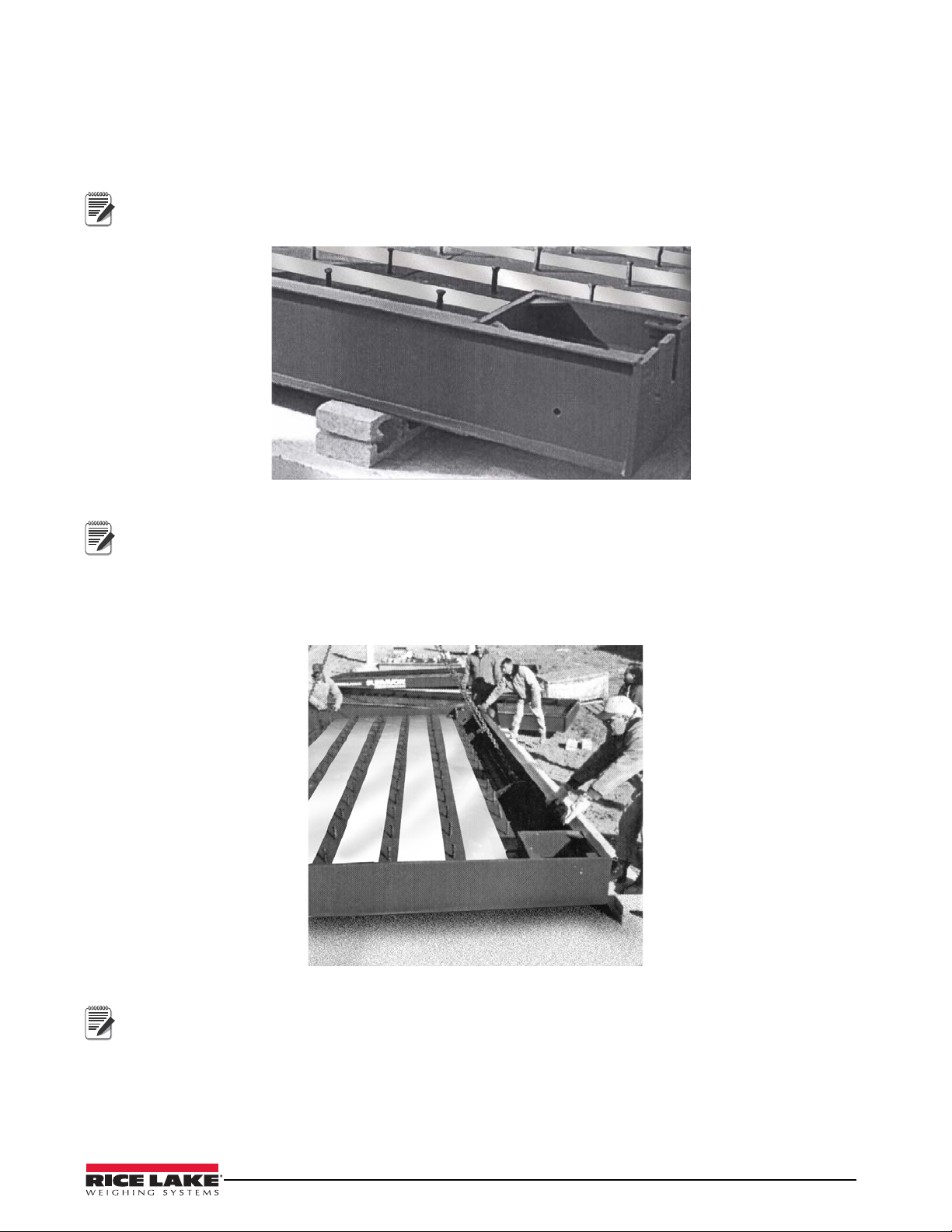
1. Begin pouring at one of the end modules, thoroughly vibrating the concrete to work it into the inside of the
main beams and around the shear connectors (see Figure 6-3).
Figure 6-3. Pouring Concrete into Module
2. Strike off and screed the concrete to further settle the concrete and level the surface (see Figure 6-4).
20 OTR Truck Scale Assembly Instructions
Figure 6-4. Screeding Concrete
Page 25

3. The first module can be bull floated to final level while the second module is being poured (see
Important
Figure 6-5). Edge all concrete/metal frame joints.
Figure 6-5. Floating Concrete
4. Pour, screed, float, and edge any remaining modules. After the concrete deck surface has hardened, brush
with a broom to provide safe traction.
5. Clean concrete splatters from the painted frame members with a wet sponge before they dry, and before
applying a liquid curing agent.
6. Apply liquid curing agent to complete concrete pour and finish (see Section 6.3).
6.3 Moist-Cure Concrete Deck
For proper curing, the surface must be kept moist for seven days. If the top surface is allowed to dry out during this
time, the finished surface is prone to unsightly spalling and surface cracking. Hot weather, full sun, and windy
conditions all accelerate surface drying.
The easiest way to keep the surface moist for seven days is to roll or spray on an epoxy-based concrete curing
solution immediately after final finishing. These epoxy-based curing products are available at contractor-supply
companies. They both seal in moisture for slow curing and protect the surface from salt and corrosion.
Some curing agents can have adverse effects on steel surfaces. Please refer to assembly prints for proper
curing agents.
Alternately, the surface can be covered with continuous plastic and kept moist by frequent flooding beneath the
plastic for the seven-day cure period.
Pour, Finish, and Cure Concrete Deck 21
Page 26

7.0 Connecting Electronic Equipment
Note
Sixty feet of six-wire homerun cable is supplied for wiring the J-box to the indicator. It is to be run in 3/4"
galvanized metal or plastic conduit from the J-box to the indicator. Conduit for this purpose is to be obtained
locally. A section of flexible conduit with connector is provided where this cable exits the J-box. Do not run any
other electrical cables in or near the conduit to the indicator.
7.1 Indicator to Peripherals
All conduit for cabling from the indicator to remote displays and other peripheral devices is to be obtained locally.
Conduit runs may be buried in a trench or secured above ground. Use separate conduit runs for AC power and DC
data lines to avoid interference. As a general guideline, run AC and DC cables in separate trenches if possible.
When DC data cables must run in the same trench as AC power lines, separate cables as much as possible.
Figure 7-1. Conduit Run in Trench
7.2 Single-Point Ground Conductor
A bare 10 gauge solid wire is run from the scale frame to the main AC power earth ground. DC transient protection
must be properly grounded to function correctly.
7.3 J-box Connections
Each J-box contains a JB8SPT summing board with DC transient protection devices. A desiccant such as the
RLWS Industrial Corrosion Inhibitor (PN 16037) should be added to the J-box enclosure before final closure.
In a truck scale up to 70' long, a single J-box is located in a J-box pocket in the center or B module (see Figure 5-1
16). A summing card mounted within the J-box is used to make all ca ble terminal connections. All terminal pins
are clearly marked as to function.
On scales over 70' long with four or more modules, two or more J-boxes are necessary.
Refer to assembly print or foundation plan for J-box location and homerun cable output.
22 OTR Truck Scale Assembly Instructions
Page 27

7.4 Electrical Ground Connections
Important
Improper grounding systems on outdoor truck scales often cause corrupted data from ground-loop
current flows and costly lightning damage to electronics.
Always strive for a single-point grounding system (see Figure 7-3 24). Do not drive ground rods at the scale
location to establish separate earth grounds for the scale. These separate earth grounds do not share the same ze ro
reference as the existing earth ground for the AC power system. This difference in electrical potential invites
ground-loop current flow between the separate grounds, often corru ptin g serial data like RS-232 which depends on
a stable zero reference.
In addition, a separate earth ground system at the scale can actually invite lightning or power surge damage:
• A minor powerline surge in the scale house electrical supply should immediately be shunted to ground. If a
separate ground system exists at the scale with a lower potential than the main ground, the surge may travel
out to the scale ground rod, damaging load cells on its way.
• A nearby lightning ground strike may instantly raise the zero potential of a ground rod at the scale location,
while leaving the scale house ground rod unaffected less. That lightning sur ge now takes the easiest path to
the lower-potential ground—through the scale wiring and back to the scale house ground, possibly
damaging the indicator on its way.
Therefore, the best grounding system for the scale is the same grounding system used for the incoming AC power
system. The 120 VAC power source used to power the indicator is connected to an existing earth grounded rod
system at the scale house or other building where the indicator is located. This should consist of a double ground
rod system of two 5/8" x 8' copper rods driven 8' deep at the service entrance where the local utility company
brings their lines into the building.
The local utility company can test the resistance of the existing ground rods with a clamp-on megohmeter that
measures zero resistance. A reading of 3¾ or less is acceptable as a ground. If the test determines that the
grounding system is inadequate, the utility company can suggest methods to improve the system. It is crucial that
the scale owner authorize and make the recommended improvements to ensure an adequate electrical ground. Do
not connect the scale to the AC power supply until the grounding system is adequate.
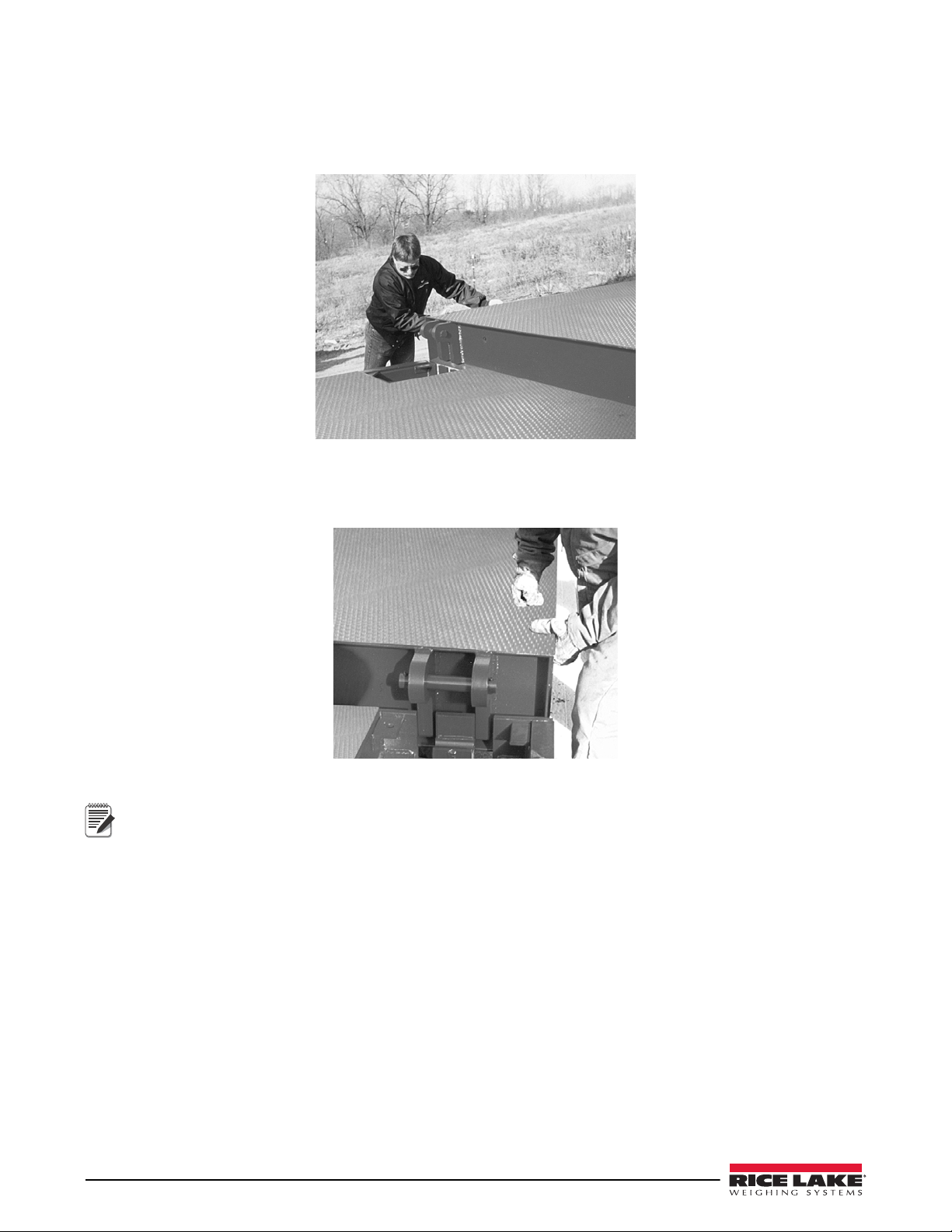
Be certain each load cell grounding strap is securely connected to the top plate and bottom plate of each load cell
mount. Some models have ground straps included to install between modules (see Figure ). These inter-module
straps ensure that the entire scale is connected to the same single point ground. There should be metal-to-metal
contact with no presence of paint or grout. This strap is designed to channel power surges on the deck around—
rather than through—the load cell to ground. These, and all, ground connections must be torqued to a specified
value and retorqued at regular service intervals. A thick coating of anti-oxidant grease should be maintained on all
ground connections to prevent corrosion
A separate grounding system conductor must ex tend
uninterrupted from the main service panel ground to the scale
to protect load cells and scale wiring from lightning and other
transient damage. This ground wire conductor must be an
unsheathed #10 copper wire or larger. Run the bare ground wire
conductor intact from the AC power ground rod to the scale in
a separate trench. Bring the wire up from the trench near the
J-box and attach it to the ground lug located in the J-box
pocket. This grounds the scale frame to the same single-point
ground as the AC power for the indicator.
A ground wire is included to attach the J-box ground lug to the
ground lug located in the J-box pocket. Grounding of the J-box
is essential for operation of the DC transient protection
incorporated into the J-box.
Figure 7-2. Inter-module Ground Strap
Connecting Electronic Equipment 23
Page 28

AC Power
Supply
#10 Copper
Ground Wire
Serial
Communication
Homerun
Cable
Load Cell
Cable
UJB-3T6
DC Transient Protection
RLWS PN 21134
TP75
DC Transient Protection.
RLWS PN 33185
TP75
DC Transient Protection
RLWS PN 33185
EL226
AC Transient Protection
RLWS PN 21136
AC Outlet
EL226
AC Transient Protection
RLWS PN 21136
AC Outlet
Fuse
Panel
Power Company Ground Rod
*Always verify that installed wiring is properly grounded
JB818ST
Junction Box
With Transient Protection
RLWS PN 66999
Ground Lug Located
on Truck Scale
Ground
Strap
DC protection board
+EXC
–EXC
+SIG
–SIG
SHLD
CELL#
CELL#
+EXC
–EXC
+SEN
+SIG
–SEN
–SIG
SHLD
+EXC
–EXC
+SIG
–SIG
SHLD
CELL#
+EXC
–EXC
+SIG
–SIG
SHLD
CELL#
+EXC
–EXC
+SIG
–SIG
SHLD
CELL#
+EXC
–EXC
+SIG
–SIG
SHLD
CELL#
+EXC
–EXC
+SIG
–SIG
SHLD
CELL#
+EXC
–EXC
+SIG
–SIG
SHLD
CELL#
+EXC
–EXC
+SEN
+SIG
–SEN
–SIG
SHLD
Ground Lug
RICE LAKE WEIGHING SYSTEMS
+EXC
–EXC
+SIG
–SIG
SHLD
Figure 7-3. Single-Point Grounding Diagram
24 OTR Truck Scale Assembly Instructions
Page 29

7.5 Installing Transient Protection
21306 REV. B
-SI
+SI
+SE
JU5 JU6 JU7 JU8 JU9 JU10 JU11 JU12
TRIM 8TRIM 7TRIM 6TRIM 5TRIM 4TRIM 3TRIM 2
-SE
SHD
+EX
-EX
CELL 2 CELL 8CELL 7CELL 6CELL 5CELL 4CELL 3CELL 1INDICATOR
TRIM 1
PT8PT7PT6PT5PT4PT3PT2PT1
RNET2RNET1 RNET3 RNET4
PT10
SECTION 3 TRIM
32 1
ON
SECTION 2 TRIM
32 1
ON
PT10
PT9
SECTION 1 TRIM
32 1
ON
SECTION 4 TRIM
32 1
ON
PT12
+EXC
-EXC
+SIG
-SIG
SHD
+EXC
-EXC
+SIG
-SIG
SHD
+EXC
-EXC
+SIG
-SIG
SHD
+EXC
-EXC
+SIG
-SIG
SHD
+EXC
-EXC
+SIG
-SIG
SHD
+EXC
-EXC
+SIG
-SIG
SHD
+EXC
-EXC
+SIG
-SIG
SHD
+EXC
-EXC
+SIG
-SIG
SHD
Ground Wire
Junction Box Ground Wire Connections
Ground Lug
J-Box
Mounting
Stud
The scale frame must be connected with 10
ga. wire to the ground lug of the transient
protection board inside the junction box.
Scales with more than one junction box require ground
straps to be installed between modules. In addition, all
junction boxes need to be connected to the scale frame.
Final ground wire connection must be at AC power
supply ground terminal or ground rod.
Note
Note
A lightning protection package comes standard on all truck scales. The individual components of this
comprehensive package are designed to protect AC and DC portions of the system. The lightning protection
package includes:
• DC transient protection included with standard J-box board(s). This DC transient protection handles up to
eight load cells. Scales with more than eight load cells require additional J-boxes.
• Self-contained DC transient protection unit in the homerun cable at the indicator.
• 115 VAC uninterruptable power supply/surge protector in the AC line before the indicator.
• Number 10 bare ground conductor cable buried in earth from scale frame to DC transient board at indicator
and finally to the AC power ground lug.
Figure 7-4. Grounding and Transient Protection on OTR Scale
Serial communications (if used) may also require transient protection to fully protect entire system. A TP-232
DC Transient Protection is suitable protection for serial communications lines. In addition, printers, remote
displays, and other devices connected to serial communications should be protected with AC transient
protection.
Connecting Electronic Equipment 25
Page 30

8.0 Trimming and Calibration
1
43
2
8
5
67
1st – Trim Side 1 Cells (1, 2, 3, 4)
2nd – Trim Side 2 Cells (5, 6, 7, 8)
3rd – Trim Sections
(1,8; 2,7; 3,6; 4,5)
Weight
Cart
Junction Box
The following section provides descriptions and procedures for load cell trimming, scale calibration and serial tag
placement.
8.1 Overview and Equipment Required
Load Cell Trimming
Individual load cell signal trimming (equalizing the signal output from each load cell) must be done first along
each side of the scale so all cells on a side have equal signal output. Adjustments are somewhat interactive, so each
side should be done at least twice.
Once that is done, load cell pairs - one from each side - are trimmed as paired sections until each sectional output is
equal. adjustments to each section should also be done at least twice.
Figure 8-1. Load Cell Trimming Diagram
Equipment Required
Both of these trimming operations can be done using a weight cart parked in various locations on the scale. Final
verification of equal output trimming, however, requires test weights to be placed on the deck in various locations.
8.2 Trimming Individual Cells
Connect all load cells to the summing board terminals in the J-box, and connect the main interface cable from the
J-box to the indicator. Power up the indicator.
Turn all load cell potentiometers (individual and section) in the J-box clockwise so all signal are at full strength.
Refer to the J-box instruction manual for proper setup of jumpers and dip switches prior to trimming, then proceed
to individual cell trimming.
Side 1
The first objective is to adjust individual load cells along one side of the scale for equal signal output when equal
weight is put on those cells. For convenience, that side of the scale is referred to as Side 1. The trimming weight
you use is the loaded weight cart.
26 OTR Truck Scale Assembly Instructions
Page 31

1. Park the cart as close as possible to side 1 being trimmed with the wheels centered over the end load cell
1
43
2
8
5
67
1
43
2
8
5
6
7
mount (Number 1 in Figure 7-2). Record the indicator reading. Remember that the scale is still
uncalibrated, so the indicator readings are simply raw counts rather than weight units.
Figure 8-2. Trimming Load Cell Number One
2. Move the cart directly over mount Number 2 and record that reading. Move the cart directly over mount
Number 3 and record that reading. Move the cart so the wheels are centered directly over mount Number 4
(you may have to turn the weight cart around so all wheels remain on the scale) and record the reading
Figure 8-3. Trimming Load Cell Numbers Two, Three, and Four
3. The lowest reading of the four is the reference cell. Do not change that cell’s signal. Instead use the
individual cell potentiometers for the other three cells to reduce those signals to match your reference cell.
Remember that you turned all pots to full signal before starting, so you can not increase the signal from any
cell; only decrease signal by trimming with the pots.
4. Note that the best trim is always the least trim. If one of the four readings differs from the others by more
than 5% of the displayed counts, there is probably a mechanical problem with that load cell mount causing
the large difference. Find it and correct it before going on. Check for binding, an out-of-level or misalign ed
link, or similar problems with the load cell and mount. Do not try to trim down large signal differences
with resistance pots - that only adds larger problems later because of interaction between mounts.
5. Park the loaded weight cart over one of the high-reading cells on Side 1. Turn that cell’s individual
potentiometer until the displayed reading equals your recorded reference cell reading. Repeat for the other
two high-reading cells on Side 1.
6. As adjustments are somewhat interactive, repeat the process in steps 1-5 until all four cells on Side 1 read
within .1% of each other.
7. Repeat steps 1-6 for load cells 5-8 on Side 2 of the scale.
Trimming and Calibration 27
Page 32

8.3 Trimming Paired Sections
1
43
2
8
5
67
1
43
2
8
5
67
Now that all individual load cells are trimmed for equal output, pairs of load cells on opposite sides of the scale
must be trimmed for equal sectional output. This process is called section trimming.
1. Park the loaded weight cart in the middle of the scale and directly over an imaginary line connecting an
end pair of cells (1 and 8 in Figure 7-4). Record the indicator reading.
Figure 8-4. Trimming Paired Section 1:8
2. Move the weight cart directly over the next paired cell section (2, 7 in Figure 3) and record the indicator
reading. Do the same for the last two paired sections (cells 3, 6, and 4, 5).
Figure 8-5. Trimming Paired Sections 2:7, 3:6 and 4:5
3. Choose the lowest reading of the four as your reference section, which is not adjusted. Using the section
potentiometers, reload the other three sections in turn and trim the sections to match the reading of the
reference section. Recheck section readings a second time as the adjustment is made can be somewhat
interactive.
4. As a final verification of the load cell trimming, do a final corner check. Place a 1000 lb weight on one
corner of the platform and record the raw-count reading on the indicator. Move the weight to all of the
other corners in turn and record those readings. The readings should be within .1% of each other.
28 OTR Truck Scale Assembly Instructions
Page 33

8.4 Calibration with Test Weights
1
43
2
8
5
67
The calibration procedure can only be done after all trimming as described in the previous page has been
completed. A qualified scale technician with a test weight truck and the expertise to accesss the scale indicator ’s
setup or calibration mode must perform the calibration procedure.
Figure 8-6. Calibration With Test Weig hts
Equipment Required
Truck scales are routinely calibrated using 25% of the capacity weight of the scale. Certified Class F test weights
equaling at least 12.5% of the scale’s capacity are required for calibrating a commercial legal-for-trade truck scale.
In addition, some type of weight for a substitution test of an additional 12.5% of the capacity is required. This can
be the test-weight truck, bags of sand, or any convenient items easy to load onto the scale. This total calibration
weight of 25% of scale capacity (12.5% test weights, 12.5% substitution weight) is required by weights and
measures officials for commercial truck scales in most states. Check with your local weights and measures officials
for the requirements in your jurisdiction.
Industrial scales not used for legal-for-trade transactions do not require certified test weights. Weight equal to 25%
of scale capacity is recommended for calibrating such scales.
See NIST Handbook 44 for detailed calibration requirements and procedures.
8.5 Serial Tag
The serial tag on an OTR truck scale is found at the e nd of the scale near the SURVIVOR logo. A duplicate tag is
placed inside of the J-box pocket.
Figure 8-7. Serial Tag Placement
Trimming and Calibration 29
Page 34

9.0 Load Cell Replacement
Load Cell Bolts
Baseplate
Link
Load Cell
90° Conduit
Connector
Load Plate
Shim
Upper Mount
Block
Grout
(optional)
Anchor
Bolt
Note
Note
Note
Use the following steps to replace load cells in the OTR truck scale:
1. Position jack on the concrete foundation beneath one of the weighbridge’s main frame members close to
the load cell mount. (Allow room for load cell removal and installation.) Raise jack approximately 1/2"
and put setting block(s) under the scale deck.
2.
Figure 9-1. Load Cell Mount
As a safety precaution, always use setting blocks when jacking scale module.
3. Disconnect the load cell terminal connections in the junction box. Disconnect the flex conduit from the
rigid conduit at the frame. Pull the load cell cable out of the conduit.
Attach a pull cord to the load cell cable at the junction box before pulling the cable through the conduit.
4. Remove the two load cell bolts and lift out load cell and link assembly.
5. Remove LB connector and flexcable. Install LB connector and flex conduit on new load cell in the same
position as was removed.
6. Install link over new load cell. Reinstall load cell and link assembly onto the baseplate. Install load cell
mount bolts. Torque bolts to 50 – 75 ft-lb.
7. Pull load cell cable through conduit using pull cord. Make a loop in flex conduit between the load cell and
the rigid conduit. Reconnect flex conduit to rigid conduit.
8. Remove setting blocks and lower scale module so that it rests on the link. Check link to verify that it is
centered and plum.
9. Connect wiring to terminals in junction box.
RLWS has 1/4" (PN 67293), 1/8" (PN 67294) and 1/16" (PN 67291) shims available to level scale. Do not exceed
over 3/4" of shims combined. If more is necessary contact RLWS for other options.
30 OTR Truck Scale Assembly Instructions
Page 35

Vehicle Scale Limited Warranty
Rice Lake Weighing Systems (RLWS) warrants that all RLWS brand equipment and systems properly installed by
a Distributor will operate in accordance with written specifications as confirmed by the Distributor and accepted by
RLWS. All systems and components are warranted against defects in materials and workmanship for 5 years from
date of shipment from the manufacturer. Furthermore, the seller warrants the fabricated weighbridge against faulty
workmanship and defective materials for 5 years from date of shipment from the manufacturer.
RLWS warrants that the equipment sold hereunder will conform to the current written specifications authorized by
RLWS. RLWS warrants the equipment against faulty workmanship and defective mate rials. If any equipment fails
to conform to these warranties, RLWS will, at its option, repair or replace such goods returned within the warranty
period subject to the following:
• Upon discovery by Buyer of such non-conformity, RLWS will be given prompt written notice with a
detailed explanation of the alleged deficiencies.
• Individual electronic components returned to RLWS for warranty purposes must be packaged to prevent electrostatic discharge (ESD) damage in shipment. Packaging requirements are listed in a publication, “Protecting Your Components From Static Damage in Shipment,” available from RLWS
Equipment Return Department.
• Examination of such equipment by RLWS confirms that the non-conformity actually exists, and was
not caused by accident, misuse, neglect, alteration, improper installation, improper repair, or improper
testing. RLWS shall be the sole judge of all alleged non-conformities.
• Such equipment has not been modified, altered or changed by any person other than RL WS or its duly
authorized repair agents.
• RLWS will have a reasonable time to repair or replace the defective equipment. Buyer is responsible
for shipping charges both ways.
• V ehicle scale products are eligible for warranty labor and mileage char ges with pre-approval by RLWS
Service Department, and only to the limits described in the vehicle scale reimbursement program.
• RLWS will not be liable for the cost of any repairs made by others.
THESE WARRANTIES EXCLUDE ALL OTHER WARRANTIES, EXPRESSED OR IMPLIED,
INCLUDING WITHOUT LIMITATION WARRANTIES OF MERCHANTABILITY OR FITNESS FOR
A PARTICULAR PURPOSE. NEITHER RLWS NOR DISTRIBUTOR WILL BE LIABLE FOR INCIDENTAL OR CONSEQUENTIAL DAMAGES.
RLWS AND BUYER AGREE THAT RLWS’ SOLE AND EXCLUSIVE LIABILITY HEREUNDER IS
LIMITED TO REPAIR OR REPLACEMENT OF SUCH GOODS. IN ACCEPTING THIS WARRANTY,
THE BUYER WAIVES ALL OTHER CLAIMS TO WARRANTY.
SHOULD THE SELLER BE OTHER THAN RLWS, THE BUYER AGREES TO LOOK ONLY TO THE
SELLER FOR WARRANTY CLAIMS.
No terms, conditions, understanding, or agreements purporting to modify the terms of this warranty shall
have any legal effect unless made in writing and signed by a corporate officer of RLWS and the Buyer.
© Rice Lake Weighing Systems, Inc. Rice Lake, WI USA. All Rights Reserved.
RICE LAKE WEIGHING SYSTEMS • 230 WEST COLEMAN STREET • RICE LAKE, WISCONSIN 54868 • USA
31
Page 36

For More Information
Web Site
• Frequently Asked Questions (FAQs) at
• http://www.ricelake.com/faqs.aspx
Contact Information
Hours of Operation
Knowledgeable customer service representatives are available 6:30 a.m. - 6:30 p.m. Monday through Friday and 8
a.m. to 12 noon on Saturday. (CST)
Telephone
• Sales/Technical Support 800-472-6703
• Canadian and Mexican Customers 800-321-6703
• International 715-234-9171
Immediate/Emergency Service
For immediate assistance call toll-free 1-800-472-6703 (Canadian and Mexican customers please call
1-800-321-6703). If you are calling after standard business hours and have an urgent scale outage or emergency,
press 1 to reach on-call personnel.
Fax
Fax Number 715-234-6967
Email
• US sales and product information at
• prodinfo@ricelake.com
• International (non-US) sales and product information at
• intlsales@ricelake.com
Mailing Address
Rice Lake Weighing Systems
230 West Coleman Street
Rice Lake, WI 54868 USA
32 OTR Truck Scale Assembly Instructions
Page 37

Page 38

230 W. Coleman St. • Rice Lake, WI 54868 • USA
U.S. 800-472-6703 • Canada/Mexico 800-321-6703 • International 715-234-9171 • Europe +31 (0) 88 2349171
© Rice Lake Weighing Systems 08/ 2014 PN 53831 Rev D
 Loading...