

Page 1
CW-90/90X
Firmware Version 1.06
Technical Manual
Checkweigher
PN 105942 Rev D
Page 2

Page 3

Contents
Technical training seminars are available through Rice Lake Weighing Systems.
Course descriptions and dates can be viewed at www.ricelake.com/training
or obtained by calling 715-234-9171 and asking for the training department.
1.0 Introduction..................................................................................................................................... 1
1.1 Safety . . . . . . . . . . . . . . . . . . . . . . . . . . . . . . . . . . . . . . . . . . . . . . . . . . . . . . . . . . . . . . . . . . . . . . . . . . 1
1.2 Overview . . . . . . . . . . . . . . . . . . . . . . . . . . . . . . . . . . . . . . . . . . . . . . . . . . . . . . . . . . . . . . . . . . . . . . . . 2
1.3 Operating Modes . . . . . . . . . . . . . . . . . . . . . . . . . . . . . . . . . . . . . . . . . . . . . . . . . . . . . . . . . . . . . . . . . 2
1.4 Keypad Functions . . . . . . . . . . . . . . . . . . . . . . . . . . . . . . . . . . . . . . . . . . . . . . . . . . . . . . . . . . . . . . . . . 2
1.5 Tare Recall . . . . . . . . . . . . . . . . . . . . . . . . . . . . . . . . . . . . . . . . . . . . . . . . . . . . . . . . . . . . . . . . . . . . . . 3
1.6 Annunciators LEDs . . . . . . . . . . . . . . . . . . . . . . . . . . . . . . . . . . . . . . . . . . . . . . . . . . . . . . . . . . . . . . . . 4
1.7 Bar Graph LEDs . . . . . . . . . . . . . . . . . . . . . . . . . . . . . . . . . . . . . . . . . . . . . . . . . . . . . . . . . . . . . . . . . . 5
2.0 Installation ...................................................................................................................................... 6
2.1 Unpacking and Assembly . . . . . . . . . . . . . . . . . . . . . . . . . . . . . . . . . . . . . . . . . . . . . . . . . . . . . . . . . . . 6
2.2 Leveling . . . . . . . . . . . . . . . . . . . . . . . . . . . . . . . . . . . . . . . . . . . . . . . . . . . . . . . . . . . . . . . . . . . . . . . . . 7
2.3 Making Power Connections . . . . . . . . . . . . . . . . . . . . . . . . . . . . . . . . . . . . . . . . . . . . . . . . . . . . . . . . . . 7
2.4 Enclosure Disassembly . . . . . . . . . . . . . . . . . . . . . . . . . . . . . . . . . . . . . . . . . . . . . . . . . . . . . . . . . . . . . 7
2.5 Load Cell Wiring . . . . . . . . . . . . . . . . . . . . . . . . . . . . . . . . . . . . . . . . . . . . . . . . . . . . . . . . . . . . . . . . . . 7
2.6 Wire Specifics . . . . . . . . . . . . . . . . . . . . . . . . . . . . . . . . . . . . . . . . . . . . . . . . . . . . . . . . . . . . . . . . . . . . 7
2.7 Cable Grounding . . . . . . . . . . . . . . . . . . . . . . . . . . . . . . . . . . . . . . . . . . . . . . . . . . . . . . . . . . . . . . . . . . 8
2.7.1 Serial Communications . . . . . . . . . . . . . . . . . . . . . . . . . . . . . . . . . . . . . . . . . . . . . . . . . . . . . . . . . . . . . . . 8
2.7.2 Digital I/O . . . . . . . . . . . . . . . . . . . . . . . . . . . . . . . . . . . . . . . . . . . . . . . . . . . . . . . . . . . . . . . . . . . . . . . . . 9
2.8 Enclosure Reassembly. . . . . . . . . . . . . . . . . . . . . . . . . . . . . . . . . . . . . . . . . . . . . . . . . . . . . . . . . . . . . . 9
2.9 Board Removal . . . . . . . . . . . . . . . . . . . . . . . . . . . . . . . . . . . . . . . . . . . . . . . . . . . . . . . . . . . . . . . . . . . 9
2.10 Battery Replacement . . . . . . . . . . . . . . . . . . . . . . . . . . . . . . . . . . . . . . . . . . . . . . . . . . . . . . . . . . . . . 10
2.11 Installing Option Cards . . . . . . . . . . . . . . . . . . . . . . . . . . . . . . . . . . . . . . . . . . . . . . . . . . . . . . . . . . . . 10
2.12 Replacement Parts and Assembly Drawings . . . . . . . . . . . . . . . . . . . . . . . . . . . . . . . . . . . . . . . . . . . 12
3.0 Configuration ................................................................................................................................ 15
3.1 Menu Navigation . . . . . . . . . . . . . . . . . . . . . . . . . . . . . . . . . . . . . . . . . . . . . . . . . . . . . . . . . . . . . . . . . 15
3.2 Audit Menu . . . . . . . . . . . . . . . . . . . . . . . . . . . . . . . . . . . . . . . . . . . . . . . . . . . . . . . . . . . . . . . . . . . . . 16
3.3 Calibration Menu . . . . . . . . . . . . . . . . . . . . . . . . . . . . . . . . . . . . . . . . . . . . . . . . . . . . . . . . . . . . . . . . . 17
3.4 Setup Menu. . . . . . . . . . . . . . . . . . . . . . . . . . . . . . . . . . . . . . . . . . . . . . . . . . . . . . . . . . . . . . . . . . . . . 18
3.4.1 SCALE Submenu . . . . . . . . . . . . . . . . . . . . . . . . . . . . . . . . . . . . . . . . . . . . . . . . . . . . . . . . . . . . . . . . . . 18
3.4.2 FEATUR Submenu . . . . . . . . . . . . . . . . . . . . . . . . . . . . . . . . . . . . . . . . . . . . . . . . . . . . . . . . . . . . . . . . . 23
3.4.3 FEATUR Menu, REGULA / INDUST Submenu . . . . . . . . . . . . . . . . . . . . . . . . . . . . . . . . . . . . . . . . . . . . 27
3.4.4 Serial, PFORMT, DIG I/O, VERS Submenus . . . . . . . . . . . . . . . . . . . . . . . . . . . . . . . . . . . . . . . . . . . . . . 29
3.5 Test Menu . . . . . . . . . . . . . . . . . . . . . . . . . . . . . . . . . . . . . . . . . . . . . . . . . . . . . . . . . . . . . . . . . . . . . . 33
3.6 Time and Date Menu . . . . . . . . . . . . . . . . . . . . . . . . . . . . . . . . . . . . . . . . . . . . . . . . . . . . . . . . . . . . . . 34
3.7 ACCUM Menu . . . . . . . . . . . . . . . . . . . . . . . . . . . . . . . . . . . . . . . . . . . . . . . . . . . . . . . . . . . . . . . . . . . 34
3.8 BRIGHT Menu . . . . . . . . . . . . . . . . . . . . . . . . . . . . . . . . . . . . . . . . . . . . . . . . . . . . . . . . . . . . . . . . . . . 34
3.9 ID Menu. . . . . . . . . . . . . . . . . . . . . . . . . . . . . . . . . . . . . . . . . . . . . . . . . . . . . . . . . . . . . . . . . . . . . . . . 35
4.0 Calibration .................................................................................................................................... 36
4.1 Front Panel Calibration. . . . . . . . . . . . . . . . . . . . . . . . . . . . . . . . . . . . . . . . . . . . . . . . . . . . . . . . . . . . . 36
4.2 EDP Command Calibration . . . . . . . . . . . . . . . . . . . . . . . . . . . . . . . . . . . . . . . . . . . . . . . . . . . . . . . . . 37
4.3 Revolution® Calibration . . . . . . . . . . . . . . . . . . . . . . . . . . . . . . . . . . . . . . . . . . . . . . . . . . . . . . . . . . . . 38
4.4 More About Calibration . . . . . . . . . . . . . . . . . . . . . . . . . . . . . . . . . . . . . . . . . . . . . . . . . . . . . . . . . . . . 38
4.4.1 Adjusting Final Calibration. . . . . . . . . . . . . . . . . . . . . . . . . . . . . . . . . . . . . . . . . . . . . . . . . . . . . . . . . . . . 38
© Rice Lake Weighing Systems. All rights reserved. Printed in the United States of America.
Specifications subject to change without notice.
Rice Lake Weighing Systems is an ISO 9001 registered company. Version 1.06
December 17 , 2014
Contents 1
Page 4

5.0 Operation....................................................................................................................................... 39
Rice Lake continually offers web-based video training on a growing selection
of product-related topics at no cost. Visit www.ricelake.com/webinars.
5.1 Range Mode . . . . . . . . . . . . . . . . . . . . . . . . . . . . . . . . . . . . . . . . . . . . . . . . . . . . . . . . . . . . . . . . . . . . 39
5.1.1 Value Set: Keyed . . . . . . . . . . . . . . . . . . . . . . . . . . . . . . . . . . . . . . . . . . . . . . . . . . . . . . . . . . . . . . . . . . 39
5.1.2 Value Set: Push . . . . . . . . . . . . . . . . . . . . . . . . . . . . . . . . . . . . . . . . . . . . . . . . . . . . . . . . . . . . . . . . . . . 40
5.2 Target Weight Mode . . . . . . . . . . . . . . . . . . . . . . . . . . . . . . . . . . . . . . . . . . . . . . . . . . . . . . . . . . . . . . 40
5.2.1 Value Set: Keyed . . . . . . . . . . . . . . . . . . . . . . . . . . . . . . . . . . . . . . . . . . . . . . . . . . . . . . . . . . . . . . . . . . 40
5.2.2 Value Set: Push . . . . . . . . . . . . . . . . . . . . . . . . . . . . . . . . . . . . . . . . . . . . . . . . . . . . . . . . . . . . . . . . . . . 41
5.3 Target Percent Mode. . . . . . . . . . . . . . . . . . . . . . . . . . . . . . . . . . . . . . . . . . . . . . . . . . . . . . . . . . . . . . 41
5.3.1 Value Set: Keyed . . . . . . . . . . . . . . . . . . . . . . . . . . . . . . . . . . . . . . . . . . . . . . . . . . . . . . . . . . . . . . . . . . 42
5.3.2 Value Set: Push . . . . . . . . . . . . . . . . . . . . . . . . . . . . . . . . . . . . . . . . . . . . . . . . . . . . . . . . . . . . . . . . . . . 42
5.4 IDs. . . . . . . . . . . . . . . . . . . . . . . . . . . . . . . . . . . . . . . . . . . . . . . . . . . . . . . . . . . . . . . . . . . . . . . . . . . . 43
5.4.1 Setting an ID. . . . . . . . . . . . . . . . . . . . . . . . . . . . . . . . . . . . . . . . . . . . . . . . . . . . . . . . . . . . . . . . . . . . . . 43
5.4.2 Using a Stored ID . . . . . . . . . . . . . . . . . . . . . . . . . . . . . . . . . . . . . . . . . . . . . . . . . . . . . . . . . . . . . . . . . . 45
5.4.3 WeighVault . . . . . . . . . . . . . . . . . . . . . . . . . . . . . . . . . . . . . . . . . . . . . . . . . . . . . . . . . . . . . . . . . . . . . . . 45
5.5 Negative Checkweighing . . . . . . . . . . . . . . . . . . . . . . . . . . . . . . . . . . . . . . . . . . . . . . . . . . . . . . . . . . . 46
6.0 Serial Commands ......................................................................................................................... 48
6.1 The Serial Command Set. . . . . . . . . . . . . . . . . . . . . . . . . . . . . . . . . . . . . . . . . . . . . . . . . . . . . . . . . . . 48
6.1.1 Key Press Commands . . . . . . . . . . . . . . . . . . . . . . . . . . . . . . . . . . . . . . . . . . . . . . . . . . . . . . . . . . . . . . 48
6.1.2 ID Commands . . . . . . . . . . . . . . . . . . . . . . . . . . . . . . . . . . . . . . . . . . . . . . . . . . . . . . . . . . . . . . . . . . . . 49
6.1.3 Reporting Commands. . . . . . . . . . . . . . . . . . . . . . . . . . . . . . . . . . . . . . . . . . . . . . . . . . . . . . . . . . . . . . . 49
6.1.4 Clear and Reset Commands. . . . . . . . . . . . . . . . . . . . . . . . . . . . . . . . . . . . . . . . . . . . . . . . . . . . . . . . . . 49
6.1.5 Parameter Setting Commands . . . . . . . . . . . . . . . . . . . . . . . . . . . . . . . . . . . . . . . . . . . . . . . . . . . . . . . . 49
6.1.6 Normal Mode Commands. . . . . . . . . . . . . . . . . . . . . . . . . . . . . . . . . . . . . . . . . . . . . . . . . . . . . . . . . . . . 53
6.1.7 Unique Commands. . . . . . . . . . . . . . . . . . . . . . . . . . . . . . . . . . . . . . . . . . . . . . . . . . . . . . . . . . . . . . . . . 53
6.2 Custom Stream Formatting . . . . . . . . . . . . . . . . . . . . . . . . . . . . . . . . . . . . . . . . . . . . . . . . . . . . . . . . . 53
7.0 Print Formatting ............................................................................................................................ 56
7.1 Print Formatting Commands . . . . . . . . . . . . . . . . . . . . . . . . . . . . . . . . . . . . . . . . . . . . . . . . . . . . . . . . 56
7.2 Customizing Print Formats. . . . . . . . . . . . . . . . . . . . . . . . . . . . . . . . . . . . . . . . . . . . . . . . . . . . . . . . . . 57
7.2.1 Using the EDP Port. . . . . . . . . . . . . . . . . . . . . . . . . . . . . . . . . . . . . . . . . . . . . . . . . . . . . . . . . . . . . . . . . 57
7.2.2 Using the Front Panel . . . . . . . . . . . . . . . . . . . . . . . . . . . . . . . . . . . . . . . . . . . . . . . . . . . . . . . . . . . . . . . 57
7.2.3 Using Revolution®. . . . . . . . . . . . . . . . . . . . . . . . . . . . . . . . . . . . . . . . . . . . . . . . . . . . . . . . . . . . . . . . . 58
8.0 WLAN Option Card......................................................................................................................... 59
8.1 WLAN Card Installation . . . . . . . . . . . . . . . . . . . . . . . . . . . . . . . . . . . . . . . . . . . . . . . . . . . . . . . . . . . . 59
9.0 Appendix ....................................................................................................................................... 60
9.1 Error Messages . . . . . . . . . . . . . . . . . . . . . . . . . . . . . . . . . . . . . . . . . . . . . . . . . . . . . . . . . . . . . . . . . . 60
9.2 Using the XE EDP Command. . . . . . . . . . . . . . . . . . . . . . . . . . . . . . . . . . . . . . . . . . . . . . . . . . . . . . . . 61
9.3 Status Messages. . . . . . . . . . . . . . . . . . . . . . . . . . . . . . . . . . . . . . . . . . . . . . . . . . . . . . . . . . . . . . . . . 61
9.3.1 Using the P EDP Command . . . . . . . . . . . . . . . . . . . . . . . . . . . . . . . . . . . . . . . . . . . . . . . . . . . . . . . . . . 61
9.3.2 Using the ZZ EDP Command . . . . . . . . . . . . . . . . . . . . . . . . . . . . . . . . . . . . . . . . . . . . . . . . . . . . . . . . . 61
9.4 Continuous Output (Stream) Format . . . . . . . . . . . . . . . . . . . . . . . . . . . . . . . . . . . . . . . . . . . . . . . . . . 62
9.5 Digital Filtering . . . . . . . . . . . . . . . . . . . . . . . . . . . . . . . . . . . . . . . . . . . . . . . . . . . . . . . . . . . . . . . . . . . 62
9.5.1 DIGFLx Parameters. . . . . . . . . . . . . . . . . . . . . . . . . . . . . . . . . . . . . . . . . . . . . . . . . . . . . . . . . . . . . . . . . 63
9.5.2 DFSENS and DFTHRH Parameters. . . . . . . . . . . . . . . . . . . . . . . . . . . . . . . . . . . . . . . . . . . . . . . . . . . . . 63
9.5.3 Setting the Digital Filter Parameters. . . . . . . . . . . . . . . . . . . . . . . . . . . . . . . . . . . . . . . . . . . . . . . . . . . . . 63
9.5.4 Audit Trail Support . . . . . . . . . . . . . . . . . . . . . . . . . . . . . . . . . . . . . . . . . . . . . . . . . . . . . . . . . . . . . . . . . 63
9.6 Regulatory Mode Functions . . . . . . . . . . . . . . . . . . . . . . . . . . . . . . . . . . . . . . . . . . . . . . . . . . . . . . . . . 64
9.7 Updating CW-90/90X Firmware. . . . . . . . . . . . . . . . . . . . . . . . . . . . . . . . . . . . . . . . . . . . . . . . . . . . . . 65
9.8 Specifications . . . . . . . . . . . . . . . . . . . . . . . . . . . . . . . . . . . . . . . . . . . . . . . . . . . . . . . . . . . . . . . . . . . 67
CW-90/90X Limited Warranty ................................................................................................................... 70
For More Information ................................................................................................................................ 71
2 CW-90/90X Checkweigher
Page 5
1.0 Introduction
WARNING
Important
CAUTION
WARNING
WARNING
This manual is intended for use by qualified service technicians responsible for installing and servicing the
CW-90/CW-90X checkweighing scale.
Manuals can viewed or downloaded from the Rice Lake Weighing Systems website at
www.ricelake.com/manuals.
1. 1 S af et y
Safety Symbol Definitions:
Indicates a potentially hazardous situation that, if not avoided could result in serious injury or death, and
includes hazards that are exposed when guards are removed.
Indicates a potentially hazardous situation
Indicates information about procedures that, if not obser
corruption to and loss of data.
that, if not avoided may result in minor or moderate injury.
Safety Precautions
Do not operate or work on this equipment unless you have read and understand the instructions and
warnings in this manual. Failure to follow the instructions o
death. Contact any Rice Lake Weighing Systems dealer for replacement manuals. Proper care is your
responsibility.
Some procedures described in this manual require work inside the indi
are to be performed by qualified service personnel only.
General Safety
Failure to heed may result in serious injury of death.
DO NOT allow minors (children) or inexper
DO NOT operate without all shields and guards in place.
DO NOT step on the unit.
DO NOT jump on the scale.
DO NOT use for purposes other then weight taking.
DO NOT place fingers into slots or possible pinch points.
DO NOT use any load bearing component that is
DO NOT use this product if any of the
DO NOT exceed the rated load limit of the unit.
DO NOT make alterations or modifications to the unit.
DO NOT remove or obscure warning labels.
Before opening the unit, ensure the power cord
Keep hands, feet and loose clothing away from moving parts.
ienced persons to operate this unit.
worn beyond 5% of the original dimension.
components are cracked.
is disconnected from the outlet.
ved, could result in damage to equipment or
r heed the warnings could result in injury or
cator enclosure. These procedures
Introduction 1
Page 6
1. 2 O ve rv i ew
Note
Note
Note
The CW-90/CW-90X is a high-speed digital weight indicator and scale base programmed to compare weight
readings with predetermined tolerance limits defining an “accept” band.
If the current weight reading is within the acceptable range, the green “ACCEPT” LED is illuminated. If the
current weight reading is less than the acceptable range, one or more of the red “UNDER” segments is illuminat
ed.
If the current weight reading is greater than the acceptable range, one or more of the yellow “OVER” segments is
illuminated.
Features include:
• L arge .8” (20.3 mm) LED display with “under,” “accept,” and “over” bands
• Full numeric keypad (CW-90 only)
• Four configurable digital inputs/outputs
• Two independent communication ports (2) full duplex, (1) unidirectional active 20
mA current loop
1.3 Operating Modes
The CW-90/CW-90X has two modes of operation:
Normal (Weighing) Mode
Normal mode is the “production” mode o
on whether a tare has been entered. LED annunciators indicate the type of weight value.
Menu mode
Most of the procedures described in this manual, including configuration and calibration, require
in Menu mode.To enter Menu mode, press the
indicator displays “AUDIT.”
If the Audit jumper is in the “OFF” position, remove the
Insert a screwdriver into the access hole and press the setup switch once to enter Menu mode.
f the indicator. The indicator displays the gross or net weight, depending
the indicator to be
MENU key (if the Audit jumper is in the “ON” position).The
large fillister head screw from the bottom of the enclosure.
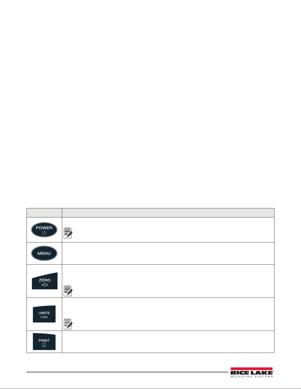
1.4 Keypad Functions
Key Function
Turns t h e CW-90/CW-90X unit on/off.
If the PC jumper is set to SW, the POWER button must be used to turn the unit on and off. If
the PC jumper is set to ON, the unit will automatically power on
only way to turn it off is to unplug power.
Enters Menu mode, allowing configuration if the Audit jumper i
key in Menu mode.
Sets the current gross weight to zero, provided the amount of weight to be removed or added is within the
specified zero range and the scale is not in motion. The zero band is defaulted to 1.9% of full scale, but can be
configured for up to 100% of full scale.
1.9% is required for legal for trade applications.
Switches the weight display to an alter
kg, g, lb, oz, or lb/oz. Conversions of the weight reading, the Tare value, the Over value, and the Under value
occur when the unit of measure is changed with the Units key.
When working in lb/oz, any entered values need to be entered in ounces. This applies when
entering over, under, target, and tare values.
nate unit. The alternate unit is defined in the Setup menu, and could be
when it’s plugged in and the
s in the “ON” position. Also used as an “escape”
Sends “on-demand” serial information out the serial port, provided the conditions for standstill are met. PRINT
will be displayed while the unit prints.
Table 1-1. Keypad Functi ons
2 CW-90/90X Checkweigher
Page 7
OVER
UNDER
TARGET
ID
ENTER
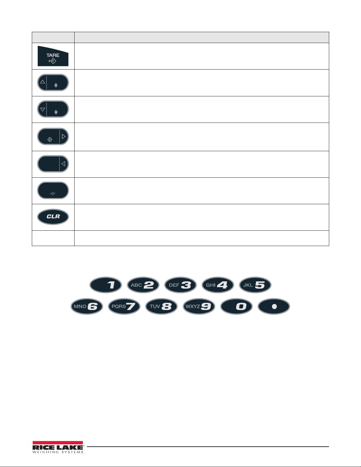
Key Function
Performs one of several predetermined Tare functions dependent on the mode of operation selected in the
TAREFN parameter (See Section 3.4.1 on page 18). To view a stored tare, see Section 1.5 on page 3.
Allows the display of the current “over tolerance” value, or allows setting the “over tolerance” value.
Allows the display of the current “under tolerance” value, or allows setting the current “under tolerance” value.
When the MODE parameter is set to TARGWT or TARG% (see Section on page 19), this key is used to acquire
a weight value and assign it as th
over/under values using the target value and the over/under tolerance settings defined during the weighing
operation.
Selects a particular over/under/tare/units register set to be retrieved and used.
Used to accept entries and move down to below parameters in Menu mode.
e desired “target” value. The CW-90/CW-90X then computes the final
CW-90 only.
Clear key. Used to backspace on entries
Numeric keypad
(see Figure 1-1)
CW-90 only.
Used to enter values directly.
Table 1-1. Keypad Functions (Continued)
Figure 1-1. CW-90 Numeric Keypad
1.5 Tare Recall
When a stored tare is displayed, the Gross and Net annunciators will be turned off and the PT annunciator will be
turned on. To display a stored tare,
1. Press the
2. Press the
The tare value will be displayed for 10 seconds. If there is no tare in the system, pressing the TAR E key will
have no effect.
MENU key.
TARE key.
Introduction 3
Page 8
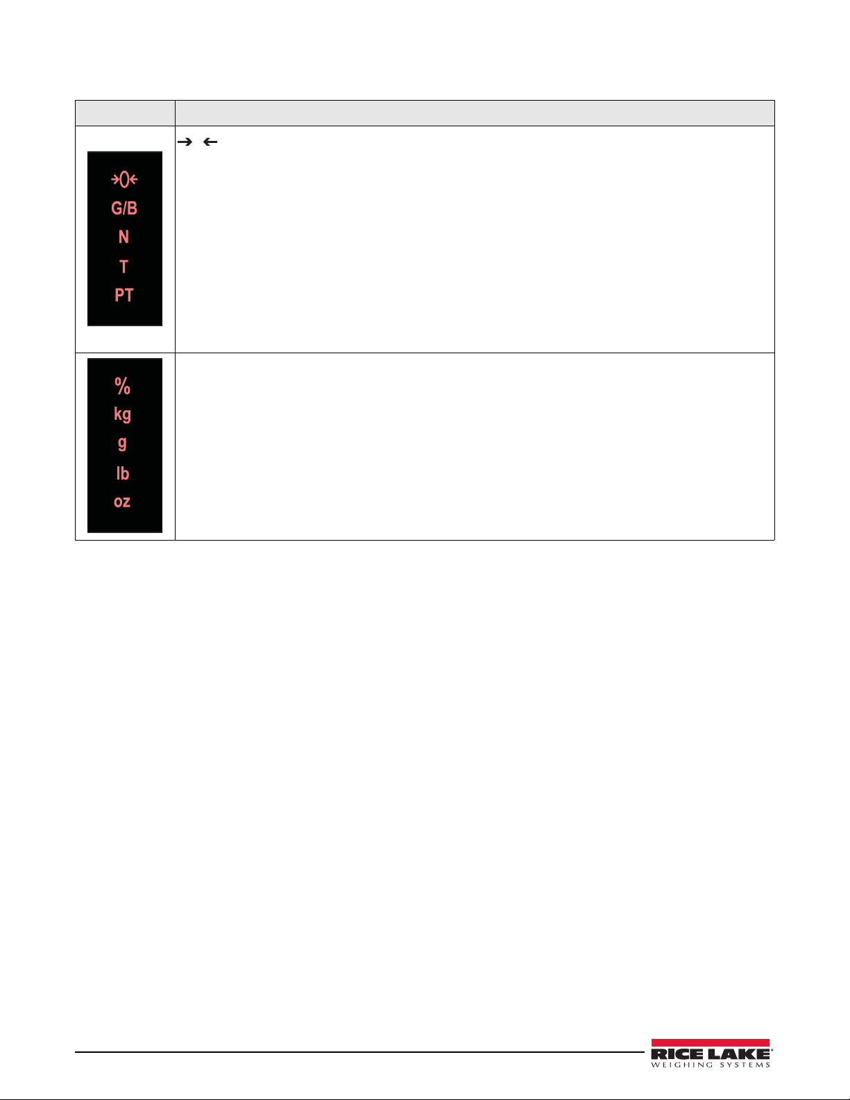
1.6 Annunciators LEDs
0
LED Description
Zero (Center of Zero) LED
While in gross weight display mode, this LED indicates that the current displayed weight reading is within
+/-0.25 display divisions of the acquired zero, or is within the center of zero band.
When in the net weight display mode, it
divisions of the center of net zero. A display division is the resolution of the displayed weight value, or the
smallest incremental increase or decrease that can be displayed or printed.
G/B LED
Gross weight mode (or B
N LED
Net weight display mode.
T LED
Indicates that a tare has been acquired and stored by the system.
PT LED
Indicates that a preset tare weight has bee
Displays which unit of measure is being used.
% LED
Percent mode
kg LED
Kilograms
g LED
Grams
lb LED
Pounds
oz LED
Ounces
rutto in OIML mode)
indicates that the current net weight reading is within +/-0.25 display
n keyed in or entered via the EDP serial port.
Table 1-2. Annunciator LEDs
4 CW-90/90X Checkweigher
Page 9
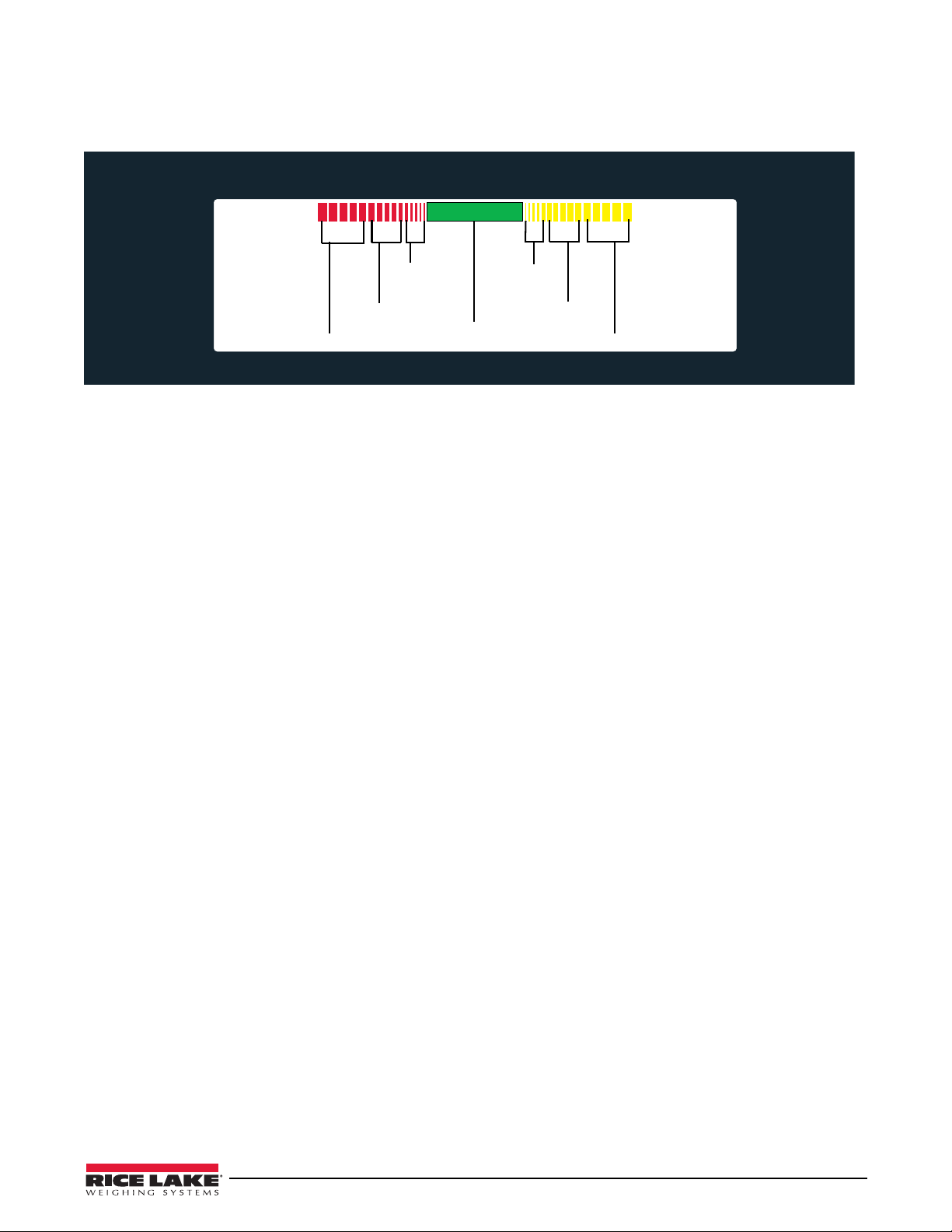
1.7 Bar Graph LEDs
ACCEPT
UNDER
OVER
Greatly over
Moderately under
Slightly under
Acceptable weight
Moderately over
Slightly over
Greatly under
The bar graph LEDs provide you with a fast way of determining if a container is too heavy (OVER), too li ght
UNDER), or is within an acceptable weight range (ACCEPT).
(
Figure 1-2. Bar Graph LEDs
You can enable the UNDER and OVER lights to act as a graph as illustrated in Figure 1-2, or to appear as one a
solid bar regardless to how far over/under a
This is done by accessing the Feature menu (see Section 3.4.2 on page 23).
Red Segments
When illuminated, this indicates an underweight
value. The leftmost red segments indicate that the container weight is far below the acceptable weight band (greatly
under); the rightmost segments indicate that the container weight is almost in the acceptable weight band, but still
under (slightly under). Illuminating the center segments indicates middle-ground, or moderately under.
weighment is. They can also be disabled so no illumiation is provided.
condition; the container weighs less than the lowest acceptable
Green Segment
Indicates an acceptable value. When lit, the green segment (one solid bar) indicates that the container
weight is
within the actual acceptable band of weight limits.
Yellow Segments
When illuminated, this indicates an overw
eight condition; the container weighs more than the highest acceptable
value. The rightmost yellow segments indicate that the container weight is far above the acceptable weight band
(greatly over); the leftmost segments indicate that the container weight is almost in the acceptable weight band, but
still over (slightly over). Illuminating the center segments indicates middle-ground, or moderately over.
Introduction 5
Page 10
2.0 Installation
1
6
9
4
2
5
7
10
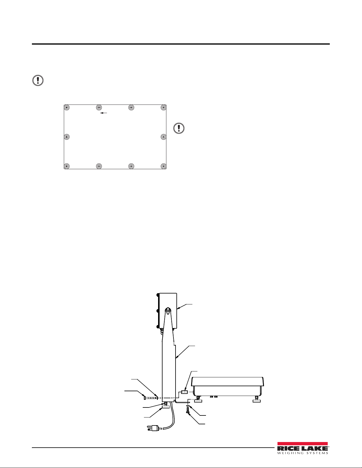
Torque
Pattern
8
3
Torqued screws may become less
tight as the gasket is compressed
during torque pattern, therefore a
second torque is required using the
same pattern and torque value.
Important
Important
Indicator
Column
Column Support
Lock Washer
Cap Screw 1/4-20NC X 3/4
Foot
Coupling Nut
Cap Screw
1/4-20NC x 1-3/4
Lock Washer
This section contains instructions on unpacking and assembly, leveling, making power connections, load cell
wiring, wiring standard serial port, optional network communications, wiring optional digital outputs, optional
backup battery operation, board diagrams, and power-up sequence.
Do not pick up the scale by the “spider” assembly which supports the platter. Lifting by the spider may
damage the load cell. Lift the scale from under the base
removed, align the gasket holes carefully to prevent driving a screw through the gasket and causing a
leak. Tighten screws to 15 in/lbs (1.7 N-m) in alternating patterns shown Figure 2-1.
Figure 2-1. Indicator Back Panel Screw Tightening Sequence
2.1 Unpacking and Assembly
The indicator head and support column or stand are shipped detached from the scale platform.
1. Remove all assemblies from the shipping ca
load cell cable. This cable is correctly wired to the load cell terminal in the indicator head. Do not pull with
excessive force on the connections at either end of this cable.
2. If mounting the head onto a column, remove the platter from the sc
3. Invert the platform to access t
he column mounting holes on the rear and bottom of the platform.
4. Position the column over the four mount
in mounting holes on bottom side of the platform. Install (2) 1/4-20 x 1-3/4”cap screws, (2) lock washers,
and (2) column supports in mounting holes on rear of platform. Install coupling nuts, counter bored end
first, onto threaded stem of rubber feet. Install feet onto bottom side of the column.
5. Turn the CW
-90/CW-90X upright and replace the platter on the platform.
6. Attach indicator to the column with the two knobs and nylon
between indicator enclosure and column mounting holes.
rton. Notice that the head and scale platform are joined by a
ing holes. Install (2) 1/4-20 x 3/4” cap screws and (2) lock washers
to move it. If the rear panel of the indicator is
ale platform and set aside.
washers provided. Position nylon washers
6 CW-90/90X Checkweigher
Figure 2-2. Mounting Column to Scale Platform
Page 11
2.2 Leveling
Note
Note
WARNING
Note
Select a location for the CW-90/CW-90X that is reasonably level and free of vibrations and air currents. Adjust the
four corner feet on the base and refer to the bubble level on the inside frame. The base should not rock and the feet
should have solid contact with the surface. If using a column, adjust the two column feet until they make solid
contact with the support surface.
Ensure the nut on each foot’s bolt is secured flush against the scale base.
2.3 Making Power Connections
The power source used for the CW-90 must be properly grounded to an acceptable earth ground. If the indicator is
remotely mounted, the platform must be separately grounded from the chassis ground screw located on the bottom
of the platform. Connect this screw with 18 gauge wire to the same earth ground system as the AC power source.
Failure to ground the base may cause static buildup and incorrect weights.
The CW-90 must be installed near an easily accessible power outlet to allow for quick disconnect in case of
emergency.
2.4 Enclosure Disassembly
The indicator enclosure must be opened to connect cables for load cells, communications, and digital
inputs/outputs.
Before opening the unit, ensure the power cord is disconnected from the power outlet. The power outlet
must be located near the indicator to allow the operator to
Ensure power to the indicator is disconnected, then place the indicator face-down on an antistatic mat. Remove the
screws holding the backplate to the enclosure body, then lift the backplate away from the enclosure and set it aside.
easily disconnect power to the unit.
2.5 Load Cell Wiring
On all complete units (indicator head and base), the load cell has been wired to the indicator’s CPU load cell
terminal at the factory. If you have purchased just the indicator head, you must wire the load cell.
Wire the cable to the CPU board’s J1 connector as shown in Table 2-1. Leave any excess cable outside of the
indicator head during installation
If using a 4-wire connection, set JP1 and JP2 to ON. If using a 6-wire connection, set JP1 and JP2 to OFF.
J1 Pin Function
1 + Signal
2 - Signal
3 + Sense
4 - Sense
5 + Excitation
6 - Excitation
Table 2-1. J1 Pin Assignments
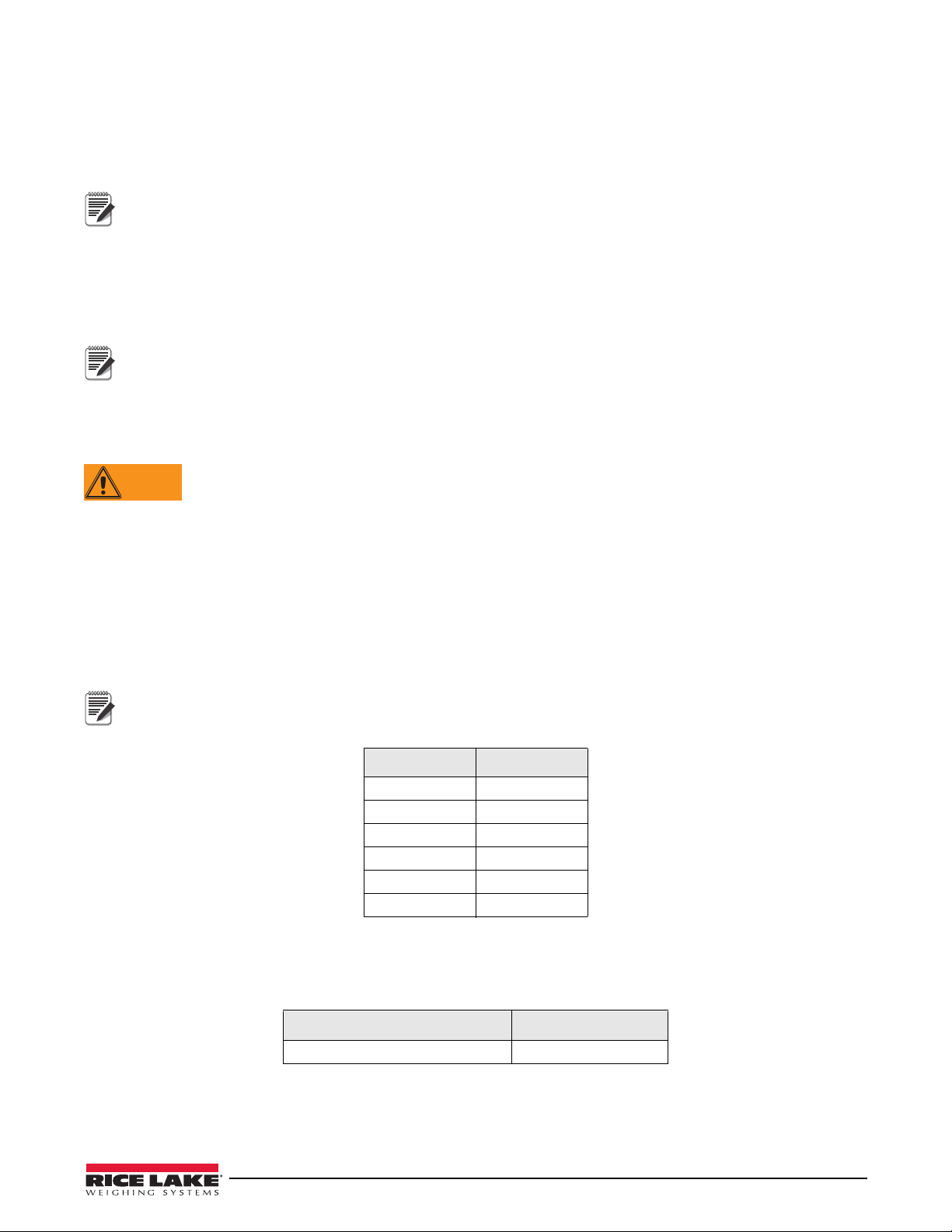
2.6 Wire Specifics
Wires connecting to J1, J2, J3, or J4 should adhere to the following specifications:
Wire Range Wire Strip Length
28~12 AWG stranded or solid wire 5~6 mm (3/16” ~ 1/4”)
Table 2-2. Wire Specifications for Connectors
Installation 7
Page 12
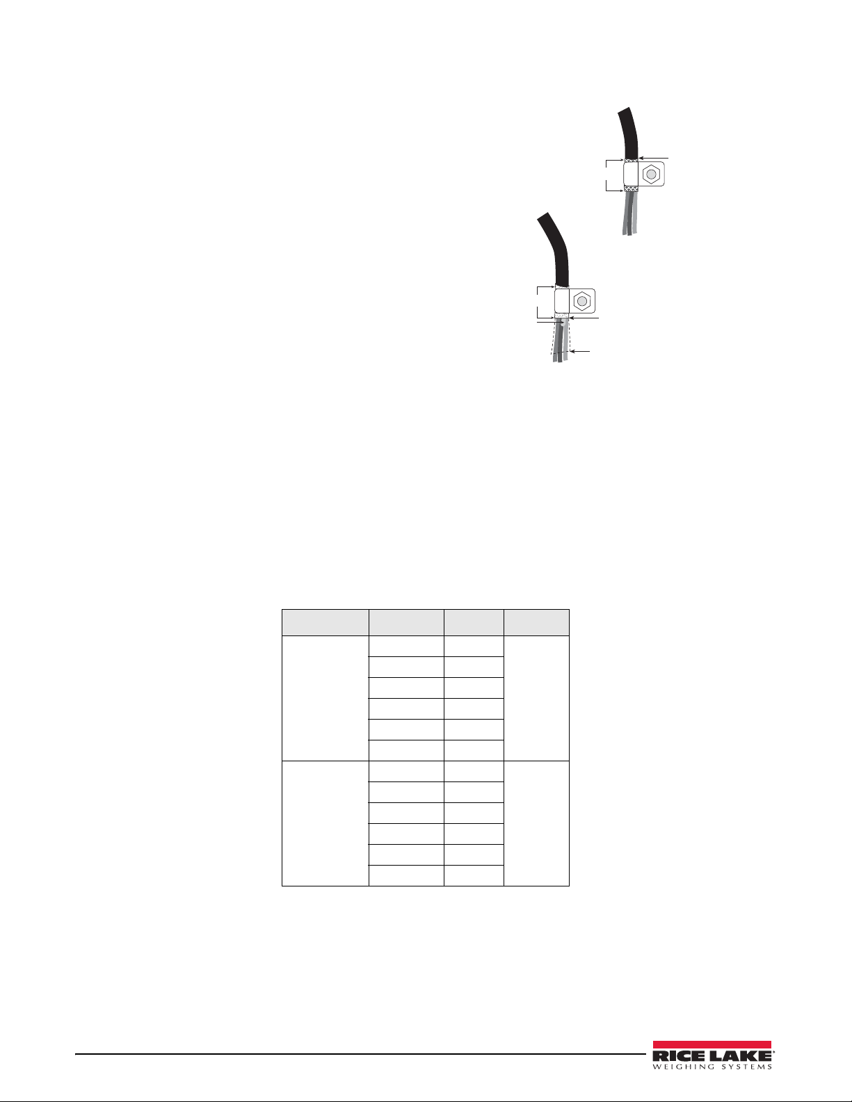
2.7 Cable Grounding
Insulated cable
Foil (silver side out)
Grounding clamp
Shield wire (cut)
Length of foil before folding
back on cable insulation
Cut insulation here
for foil-shielded cables
Braid
Cut insulation here
for braided cables
NOTE: Install lockwashers
first, against backplate,
under grounding clamp
Figure 2-3. Grounding Clamp Attachment for
Foil-Shielded and Braided Cabling
Except for the power cord, all cables routed through the
cord grips should be grounded against the indicator
enclosure. Do the following to ground shielded cables.
• Use the lockwashers, clamps, and kep nuts
provided in the parts kit to install grounding
clamps on the enclosure studs adjacent to cord
grips. Install grounding clamps only for cord
grips that will be used; do not tighten nuts.
• Route cables through cord grips and grounding
clamps
reach cable connectors. Mark cables to remove
insulation and shield as described below:
• For cables with foil shielding, strip insulation and
foil from the cable half
grounding clamp (see Figure 2-3). Fold the foil
shield back on the cable where the cable passes
throug
side of foil is turned outward for contact with the
grounding clamp.
• For cables with braided shielding, strip cable
insu
of insulation only to expose the braid where the cable passes through the clamp (see Figure • on page 8).
• F inish installation using cable mounts and ties to secure ca
to determine cable lengths required to
an inch (15 mm) past the
h the clamp. Ensure silver (conductive)
lation and braided shield from a point just past the grounding clamp. Strip another half inch (15 mm)
bles inside of indicator enclosure.
2.7.1 Serial Communications
Wire the serial communications cables to J2, which is Port 1 (5-wire RS-232 port). J3 is Port 2 (RS-232 and 20
mA). Connect communications cables to J2 and J3 as shown in Table 2-3.
Use cable ties to secure serial cables to
Port 1 supports full duplex RS-232 communications only; Port 2
the inside of the enclosure.
provides either active 20 mA output or duplex
RS-232 transmission. Both ports are configured using the SERIAL menu. See Section 3.4.4 on page 29.
Connector Pin Signal Port
J2 1 Ground 1
2 Ground
3 Tx
4 Rx
5 DTR
6 RTS
J3 1 20mA+ 2
2 Ground
3 Tx
Table 2-3. J2 and J3 pin assignments
4 Rx
5 CTS
6 RTS
8 CW-90/90X Checkweigher
Page 13
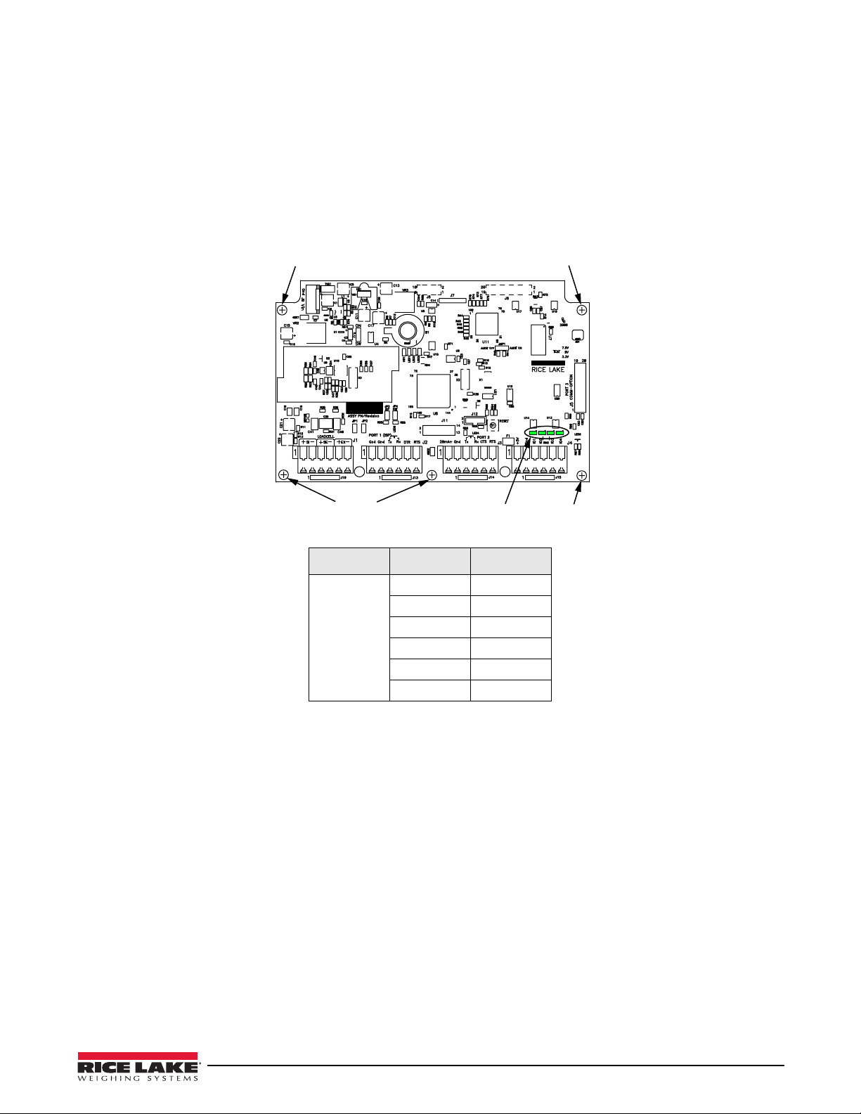
2.7.2 Digital I/O
Screws
Screw
The Digital I/O can be configured as either digital inputs or digital outputs as determined by the DIO menu (see
Section 3.4.4 on page 29). The inputs are active (on) with low voltage (0 VDC) and can be driven by TTL or 5V
logic without additional hardware. Use the
inputs. LEDs on the CPU board
light when digital inputs are active (see Figure 2-4).
Digital outputs are typically used to
DIG I/O menu (see Section 3.4.4 on page 29) to configure the digital
control relays that drive other equipment. Outputs are designed to sink not
source, switching current. Each output is a CMOS circuit, capable of sinking 24 mA when active. Digital outputs
are wired to switch relays when the digital output is active (low, 0 VDC) with reference to 5 VDC supply. LEDs on
the CPU board light up when the digital outputs are active (see Figure 2-4).
Screw
DIO LEDs
Figure 2-4. Digital I/O lights and screw locations
Connector Pin Signal
J4 1 +5V
2 Ground
3 DIG I/O 1
4 DIG I/0 2
5 DIG I/O 3
6 DIG I/O 4
Screw
Table 2-4. J4 Pin Assignments (Digital I/0)
2.8 Enclosure Reassembly
Once the cabling is complete, position the backplate over the enclosure and reinstall the screws. Use the torque
pattern shown in Figure 2-1 on page 6 to prevent distortion. Torque to
15 in/lbs (1.7 N-m).
2.9 Board Removal
If you must remove the CW-90/CW-90X CPU board, use the following procedure:
1. Disconnect power to the indicator. Remove backpla
2. Disconnect power supply cable from connector J9 on the CW
3. Disconnect the wires at the following connectors: J1, J2,
4. There are two boards: the CPU board and the keypad disp
the CPU board (see Figure 2-4), then lift the board out of the enclosure.
T o replace the CPU board, reverse the above procedure. Be sure to
indicator enclosure.
te as described in Section 2.4 on page 7.
-90/CW-90X CPU board.
J3, J4.
lay board. Remove the five screws connecting
reinstall cable ties to secure all cables inside the
Installation 9
Page 14

2.10 Battery Replacement
CAUTION
Note
CAUTION
Risk of explosion if battery is replaced with incorrect type.
Dispose of batteries per manufacturer instructions.
The lithium battery on the CPU board maintains the real-time clock and protects data stored in the system RAM
when the indicator is not connected to AC power. Data protected by this battery includes time and date, IDs, and
configuration information. If any data is lost, the indicator configuration can be restored from the PC. Watch for the
low battery warning on the LCD display and periodically check the battery voltage on the CPU board. Batteries
should be replaced when the indicator low battery warning comes on, or when battery voltage falls to 2.2 VDC.
Life expectancy of the battery is 10 years. Use Revolution to store a copy of the configuration before attempting to
replace the battery.
For best results, replace the battery while in weigh mode a
nd with AC power applied. use care not to bend the
battery retaining spring.
2.11 Installing Option Cards
Option cards are not hot-pluggable. Disconnect power cord entirely before installing option cards.
Ethernet port is not suitable for connection to circuits used outside the building and is subject
power faults.
to lightning or
Each option card is shipped with installation instructions specific to that card. For specific instructions on the
WLAN card, refer to Section 8.0 on page 59.
The general procedure for all option cards is:
1. Disconnect power cord from the indicator.
2. Remove the backplate as described in Section 2.4.
3. Install the plastic standoffs in the standof
4. Carefully align the option card connector with the J5 connector on
5. Press down firmly to seat the option
6. Make connections to the option ca
f holes (shown as black-shaded circles in Figure 2-5).
the CPU board.
card in the CPU board connector.
rd as required. Use cable ties to secure loose cables inside the enclosure.
When installation is complete, reassemble the enclosure as described in Section 2.8.
10 CW-90/90X Checkweigher
Page 15
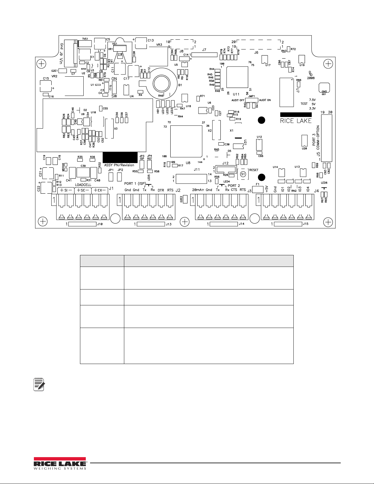
Figure 2-5. CW-90/CW-90X CPU Board
Note
Jumper Description
JP1/JP2 Jump excitation to sense. If using a 4-wir
and JP2 on. If using a 6-wire load cell cable, take JP1 and JP2 off.
Default is ON.
JP3/JP4 Used when upgrading firmware. The jumpers
upgrading firmware and off when the update is complete.
PC Power control. If the jumper is set to SW, the POWER key can be used
turn the unit on/off. If set to ON, the unit will power on when
to
plugged in and can only be powered off by unplugging.
JMP1 If set to Audit ON, calibration and conf
through the front keypad. If set to Audit OFF, calibration and
configuration can only be accessed by removing the screw on the
base of the unit and pressing the Setup switch with a screwdriver.
Default is Audit ON.
e load cell cable, leave JP1
should be on when
iguration can be acessed
Table 2-5. Jumper Descriptions
If the RESET button on the CPU board is pressed, the indicator will perform a reboot.
Installation 11
Page 16
13
30
31
22
21
8
5
18
17
15
34
28
27
19
16
26
24
25
9
7
6
3
20
4
10
12
11
10
10
11
11
1
33
29
2
14
32
23
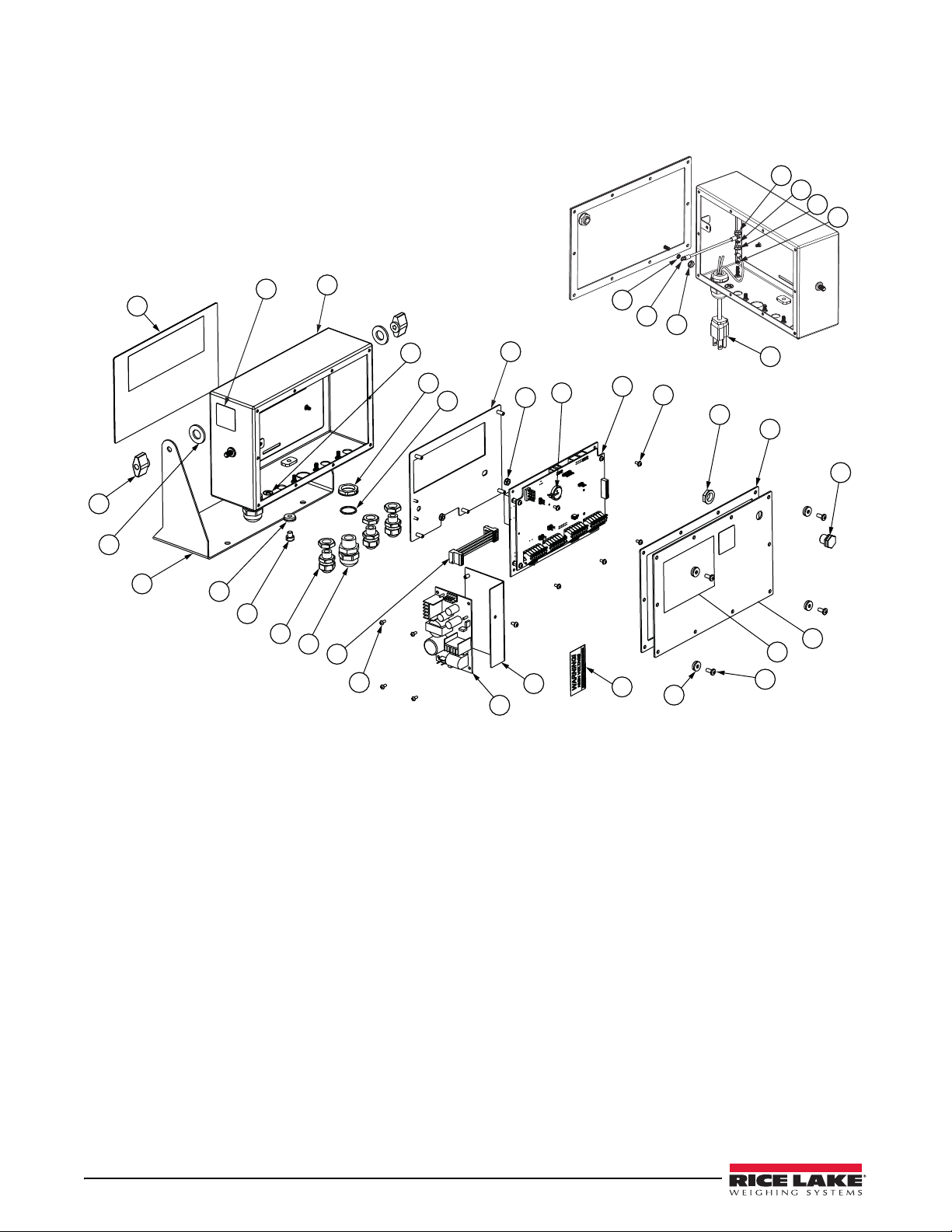
2.12 Replacement Parts and Assembly Drawings
12 CW-90/90X Checkweigher
Figure 2-6. CW-90/CW-90X Assembly and Components
Page 17

Item No. Part No. Description (Quantity)
1 Enclosure 1
2 Mounting Plate, Display 1
3 14621 Nut, Kep 6-32NC HEX 2
4 85202
85203
5 68600 Cord Grip, PG11 1
6 68599 Seal Ring, Nylon PG11 1
7 68601 Nut, PG11 1
8 58983 Cable Grip, SL-7 w/Nut 3
9 16892 Label, Earth Ground 1
10 15134 Washer, Lock NO 8 Type A 3
11 14626 Nut, Kep 8-32NC HEX 3
12 45043 Wire, Ground 4in W/No. 8 1
13 104914
104915
14 105850 Bracket, Power Supply 1
15 76556 Power Supply, Switching 1
16 14822 Screw, Mach 4-40NC x 1/4 6
17 14825 Screw, Mach 4-40NC x 1/4 4
18 105976 Cable Assy, Power Supply 1
19 102354 CPU 1
19 105741 Display 1
20 69291 Battery, 3v Coin Lithium 1
21 42640 Screw, Mach 1/4-28NF X 1/4 1
22 44676 Washer, Bonded Sealing 1
23 Backplate 1
24 84388 Gasket, Backplate 420 1
25 88733 Vent, Breather Sealed 1
26 88734 Nut, Breather Vent 1
27 14862 Screw, MACH 8-32NCx3/8 4
28 45042 Washer, Bonded Sealing SST 4
29 29635 Stand, Tilt SST 1
30 103988 Washer, Nylon .52 ID 2
31 103610 Knob, Black 1/4-20 2
32
33 53308 Label 1
34 16861 Label, Warning High 1
-- 105945 Parts Kit, CW-90/90X 1
-- 107476 Bench Scale Foot
-- 105555 Coupling Nut for Feet and Overload Stops
53307 Label 1
Power Cord Assy, 120VAC
Power Cord Assy, 230VAC
Overlay, Membrane Swit
Overlay, Piezo (CW-90X)
ch (CW-90)
Figure 2-7. CW-90/CW-90X Replacement Parts
1
1
Installation 13
Page 18
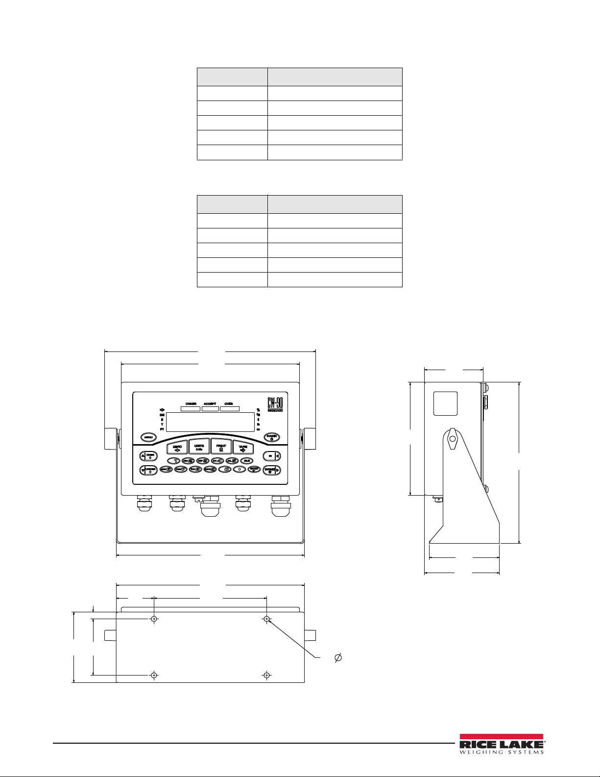
Scale Capacity Load Cell Part Number
11.24
9.50
10.02
10.02
4x .281
.38
3.75
2.01
6.00
3.00
3.75
3.12
6.00
8.57
4.00
5 lb 107174
10 lb 107174
25 lb 107175
50 lb 107176
100 lb 107177
Table 2-6. CW-90X Load Cells
Scale Capacity Load Cell Part Number
5 lb 107756
10 lb 107757
25 lb 107758
50 lb 107759
100 lb 107760
Table 2-7. CW-90 Load Cells
Figure 2-8. CW-90/CW-90X Dimensions
14 CW-90/90X Checkweigher
Page 19
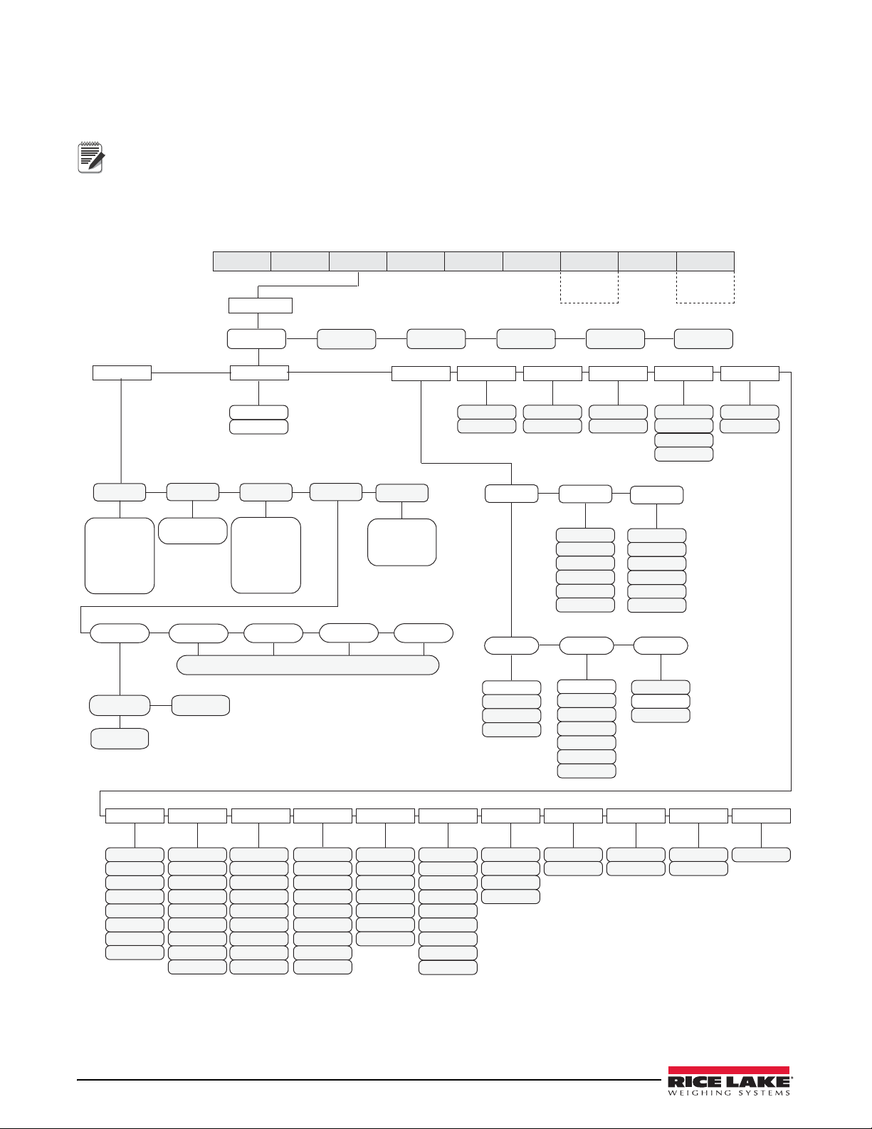
3.0 Configuration
AUDIT
Only displayed if
turned on
from Setup menu
Only displayed if
turned on
from Setup menu
CALIBR SETUP TEST EXIT
ID ACCUM BRIGHTT&D
OVER
UNDER
MENU
ID
ENTER
TARGET
Move UP/
Increment
Value
Move DOWN/
Decrement
Value
BackspaceEnter/Exit
Configuration
Menu
Enter VALUE/
Move DOWN
Move LEFT/
Previous
Move RIGHT/
Next
Note
Note
To set up and configure the CW-90/CW-90X checkweigher, you will either use the Menu key on the front panel or
press the setup switch on the bottom of the indicator. The indicator is defaulted at the factory with the audit trail
jumper (JMP1) in the ON position, allowing configuration access by pressing the
will take you to the Audit menu selection. Use the
selections. Use the
UNDER ( ) and OVER ( ) navigation key s to enter and exit menu selections, respectively.
ID ( ) and TARGE T ( ) navigation keys to move to other menu
Menu key. Pressing the Menu key
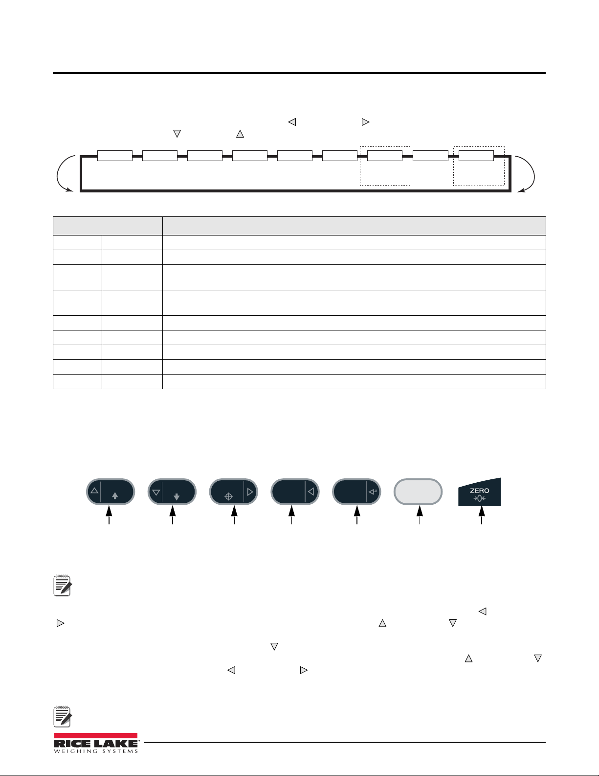
Figure 3-1.
Menu Function
AUDIT Audit Trail Displays the legally relevant (LR) firmware versi
CALIBR Calibrate Calibrates the scale.
SETUP Setup Accesses setup options for the scale, features, serial
and displays the version number.
TEST Te st Performs a basic test on the A/D, digital inputs and ou
keypad.
EXIT Exit Exits Configuration mode and r
T&D Time & Date Allows you to view and change time and date.
ACCUM Accumulator Displays the current accumulator
BRIGHT Brightness Adjusts display intensity on a scale fr
ID ID Allows you to setup or edit IDs.
Menu Mode Navigation Structure
on, configuration count, and calibration count.
output, print format, digital inputs and outputs,
tputs, communication ports, RAM, and
eturns to the weigh screen.
value.
om 0 (dimmest) to 7 (brightest).
Table 3-1 . Menu Menu Summary
3.1 Menu Navigation
Once you have entered the menus, you can use the front panel buttons to nav iga te. Note the loop ed me nu st ructur e
shown in Figure 3-1. This provides a shortcut for a
vice-versa for the opposite side of the men
u. This shortcut also holds true for sub-menu navigation.
ccessing the rightmost menu items by navigating to the left, and
Figure 3-2. Front Panel Key Functions in Menu Mode
During calibration, the ENTER key acts as a data entry confirmation key. It also acts as an EXECUTE key and
accepts the value upon successful calibration. On the CW
backspace.
-90, the ZERO or CLR key can be used for a
Various keys are used as directional keys to navigate through the menus (see Figure 3-2). The ID ( ) and TAR GE T
( ) keys scroll left and right (horizontally) on the same menu level; OVER ( ) and UNDER ( ) move up and down
(vertically) to different menu levels. These
ENTER key has the same function as UNDER ( ) when navigating the menu; either will move down to access
The
sub-categories of a main menu item. When addin
keys will edit the blinking digit. The
CW-90, whose numeric keys can be used to insert a digit to the right of the blinking digit. Press
keys have a directional symbol indicating its menu navigation function.
g or editing data using the CW -90X, the OVER ( ) and UNDER ( )
ID ( ) and TA RG ET ( ) keys navigate to another digit. This also applies to the
ENTER to accept
the data and return to the next menu item.
To exit Configuration and return to weighing, press the MENU key or navigate to the EXIT menu and press
ENTER.
Configuration 15
Page 20
3.2 Audit Menu
CALIB
Number
EXIT
EXIT T&DTESTSETUPAUDIT
XXXXXXX
CALIBR BRIGHTACCUM
Only displayed if
turned on
from Setup menu
ID
Only displayed if
turned on
from Setup menu
LR,V.
CONFIG
Number
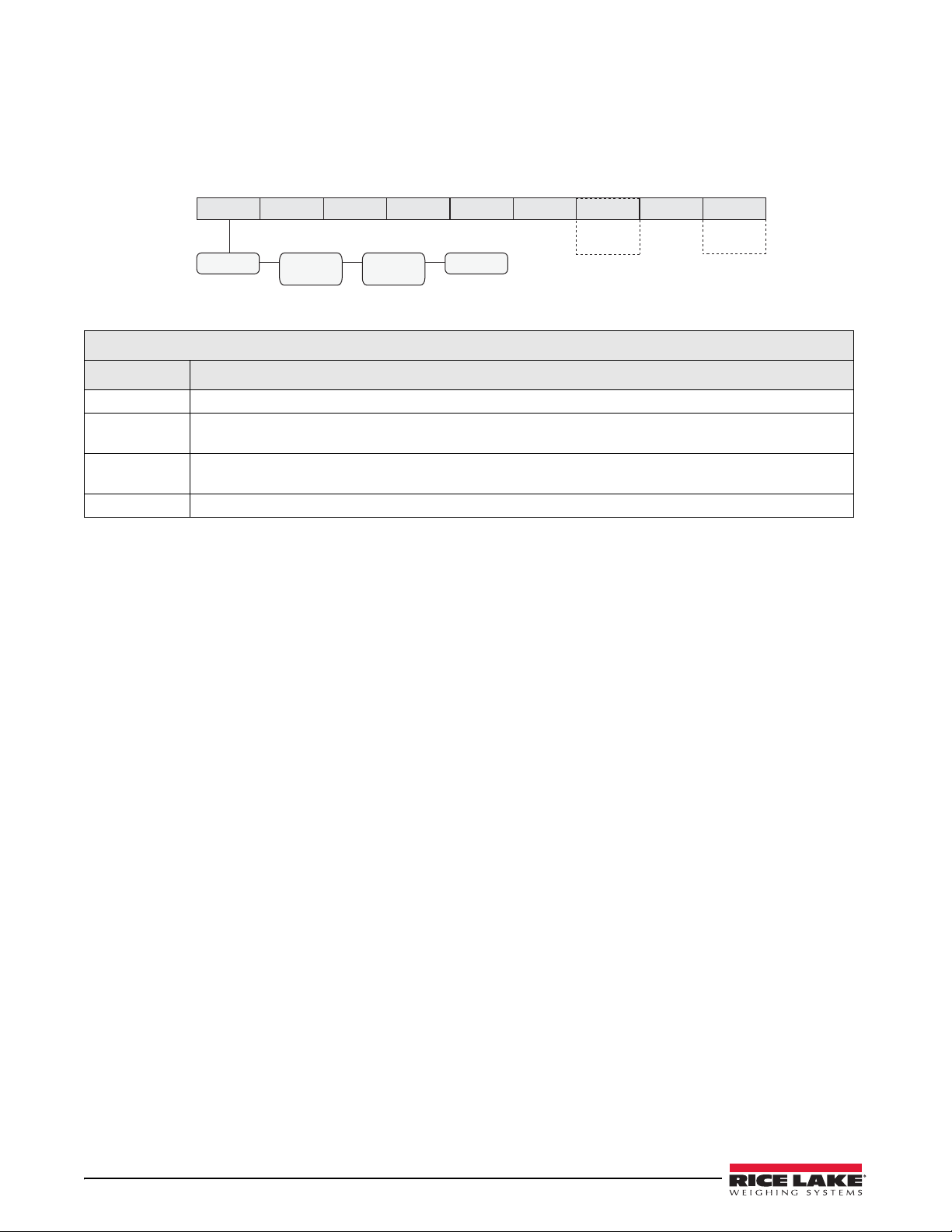
The audit menu accesses audit trail support. It provides tracking information for configuration and calibration
events. To prevent potential misuse, all configuration and calibration changes are counted as change events. Audit
information can be printed by pressing the
menu.
AUDIT Menu
Parameter Description
LR.V. Legally relevant firmware version.
CALIB Number Displays total calibration events. The
four-digit number.
CONFIG
mber
Nu
EXIT Exits the audit trail and returns to weigh mode.
Displays total configuration events. The display alternates (in one-second intervals) between CFG and the
four-digit number.
PRINT key while displaying the audit trail items beneath the AUDIT
Figure 3-3. Audit Menu
display alternates (in one-second intervals) between CALIB and the
Table 3-2. Audit Menu Parameters
16 CW-90/90X Checkweigher
Page 21
3.3 Calibration Menu
Note
WZERO
Calibrating, please wait
Calibrating, please wait
Display and edi
Press Enter
to calibrate zero
t
test weight value
WVAL WSPAN
Press Enter to
remove offset from
zero and span
calibrations
REZEROWLIN
POINT–> 1
POINT–> 2
POINT–> 3
POINT–> 4
POINT–> 5
Same as POINT-> 1
WGT 1
number
Calibrating, please wait
Press Enter
to calibrate span
EXIT T&DTESTSETUPAUDIT
XXXXXXX
CALIBR BRIGHT
Press Menu
to cancel
Press Menu
to cancel
Previous A/D raw
counts are shown
Previous A/D raw
counts are shown
ACCUM
Only displayed if
turned on
from Setup menu
CAL1
ID
Only displayed if
turned on
from Setup menu
Note
Note
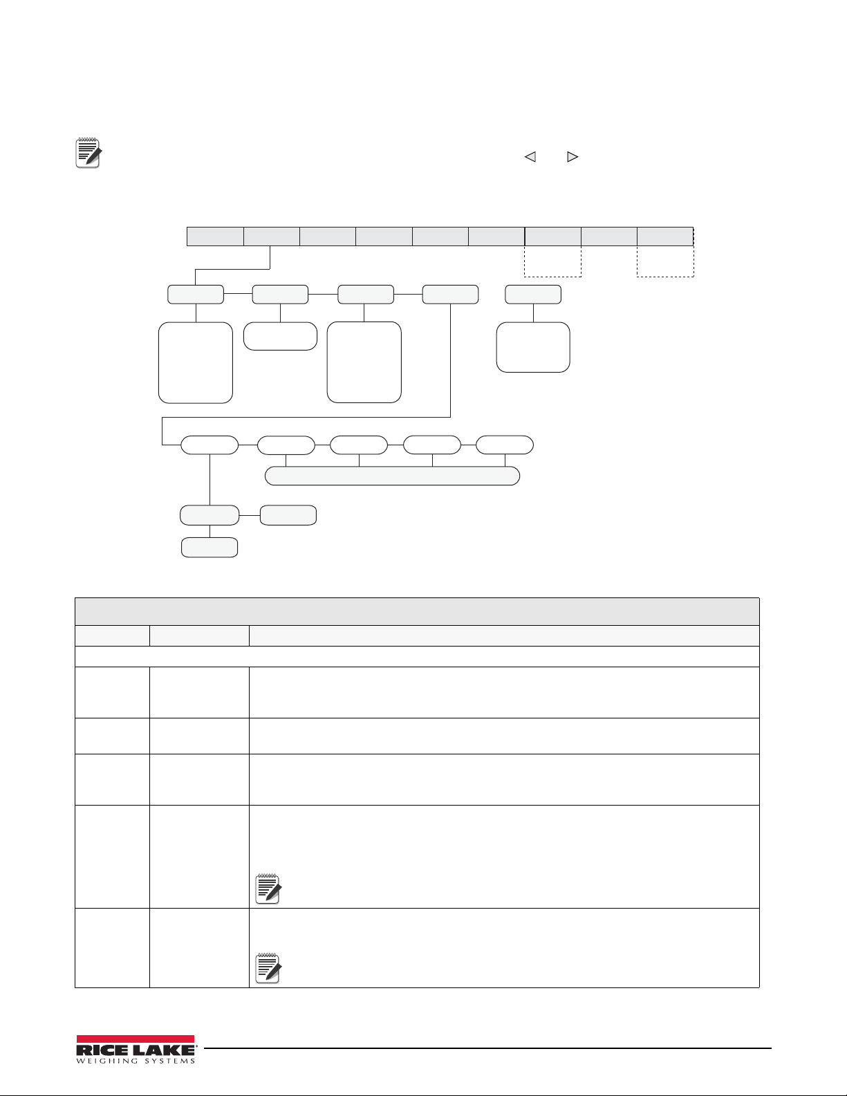
See Section 4.0 on page 36 for calibration procedures. The Calibration menu can be protected by assigning a
password in the Feature menu.
When entering a floating point value, the decimal point will appear and flash on the far right (if it is not already
on the screen). To move the decimal, press ENTER, then use the
desired location.
The CW-90/CW-90X requires the WZERO and WSPAN points to be calibrated. The linearity points are optional, but must
NOT duplicate zero or span. During calibration, the ENTER key acts as a data entry confirmation key. It also acts as an
EXECUTE key, and accepts the value if calibration was successful.
and keys to move the decimal to the
Figure 3-4. Calibration Menu
CALIBR Menu
Parameter Choices Description
Level 2 submenus
WZERO — Press ENTER and the A/D raw counts will be displayed.
Press ENTER again to calibrate zero, or press MENU to cancel. “CALIBRATING, PLEASE
AIT” will be appear prior to automatically moving to WVAL.
W
WVAL — Press ENTER to display and edit the test weigh
WSPAN.
WSPAN — Press ENTER and the A/D raw count
press MENU to cancel. “CALIBRATING, PLEASE WAIT” will be appear prior to automatically
moving to WLIN.
WLIN PT->1 — PT->5 WGT 1 allows you to display and edit the
CAL1 allows you to calibrate and display the raw A/D value. Pr
REZERO — Press ENTER to remove an offset value from the
calibration. Press ENTER to will move to the next calibration point.
chains are being used during calibration).
The linearity points are optional, but must NOT duplicate zero or span. They
must be between zero and span.
Use this parameter only after WZERO and WSPAN have been set. See
Section 4.1 on page 36 for more information about using
s will be displayed. Press ENTER to calibrate the span or
test weight value. Press ENTER to edit the value.
zero and span calibrations (e.g. if hooks or
t value. Press ENTER again to move to
ess TARE to perform
this parameter.
Table 3-3. Calibrat ion Menu Parameters
Configuration 17
Page 22
3.4 Setup Menu
Note
5000
number
OVRLOA
FS+2%
FS+9D
FS+1D
FS
MOTBAN
1
number
DFSENS
32OUT
64OUT
2OUT
8OUT
4OUT
16OUT
128OUT
DFTHRH
20D
50D
250D
5D
2D
10D
100D
NONE
200D
SMPRAT
30HZ
60HZ
7.5HZ
15HZ
120HZ
480HZ
240HZ
960HZ
PWRUPM
GO
DELAY
TAREFN
BOTH
PBTARE
NOTARE
KEYED
DFLTR1
64
128
4
16
8
32
256
1
2
ACCUM
OFF
ON
VISIBL
ON
OFF
GRADS
CALIBR
SCALE
FEATUR
SERIAL DIGI/OPFORMT VERS
SSTIME
number
10
THRESH
0
UNITS DECPNT DSPDIV
PRIMRY
LB/OZ *
KG
OZ
G
LB
888888
1D
5D
2D
* Not legal for trade
888880
8.88888
88.8888
8888.88
888.888
88888.8
SEC
LB/OZ *
LB
G
OZ
LB/OZ*
KG
OFF
TER
G
OFF
KG
LB
OZ
LB/OZ*
DFLTR2
64
128
4
16
8
32
256
1
2
DFLTR3
64
128
4
16
8
32
256
1
2
Display and edit
test weight value
WVAL WLIN
WZERO
Calibrating, please wait
Press Enter
to calibrate zero
Press Menu
to cancel
Previous A/D raw
counts are shown
WSPAN
Calibrating, please wait
Press Enter
to calibrate span
Press Menu
to cancel
Previous A/D raw
counts are shown
CONFIG
EXIT T&DTESTSETUPAUDIT
XXXXXXX
CALIBR BRIGHTACCUM
Only displayed if
turned on
from Setup menu
ID
Only displayed if
turned on
from Setup menu
Calibrating, please wait
Press Enter to
remove offset from
zero and span
calibrations
REZERO
ZTRKBN
number
0
ZRANGE
1.900000
number
FORMAT
POINT–> 1
POINT–> 2
POINT–> 3
POINT–> 4
POINT–> 5
Same as POINT-> 1
WGT 1
number
CAL1
The setup menu allows you to configure settings for the scale, features, serial port settings, print format, and digital
inputs and outputs. You can also view the software and regulatory versions, and revert to default settings.
If RANGE is displayed after a setup value is entered, the value is too large or small for the given parameter.
3.4.1 SCALE Submenu
Calibration can be performed in two places within the menu: the CALIBR menu shown in Figure 3-5 is an in-depth
scale setup and calibration. A “quick acc
ess” calibration is shown in Figure 4.1 on page 36.
18 CW-90/90X Checkweigher
Figure 3-5. Setup Menu: Scale Submenu
Page 23
SCALE Menu
Note
Note
Note
Parameter Choices Description
Level 3 submenus
CALIBR WZERO
WVAL
WSPAN
WLIN
REZERO
GRADS 10000
1–100000
See Section 3.3 on page 17 for descriptions, and see Section 4.0 on page 36 for
calibration procedures.
Calibration can be perfor
Figure 3-5 is an in-depth scale setup and calibration. A “quick access” calibration is shown
in Figure 4.1 on page 36.
Specifies the number of full scale graduations.
The value entered must be in the range 1–100000 and should be consistent with legal
equirements and environmental limits on system resolution.
r
To calculate GRADS, use the formula: GRADS = Capacity / Display Divisions.
Display divisions are specified under
med in two places within the menu: the CALIBR menu shown in
the FORMAT submenu.
If RANGE is displayed after the value is entered, the value is too large or
small for the given parameter.
FORMAT PRIMRY
SEC
TER
ZTRKBN 0
number
ZRANGE 1.900000
number
MOTBAN 1
number
OVRLOA FS+2%
FS+1D
FS+9D
FS
SSTIME 10
number
SMPRAT 30HZ
7.5HZ
15HZ
60HZ
120HZ
240HZ
480HZ
960HZ
Select your primary, secondary, and tertiary units of me
oz, and g. Secondary and tertiary units can also be set to lb/oz (lb/oz is not legal for trade),
or off.
Automatically zeroes the scale when
within the ZRANGE and scale is at standstill. Specify the zero tracking band in ± display
divisions. Maximum legal value varies depending on local regulations.
For scales using linear calibration, do not set the zero tracking band to a
value greater than that specified for the first linearization point.
Selects the range within which the scale can be zer
1.9% around the calibrated zero point, for a total range of 3.8%. Indicator must be at
standstill to zero the scale. Use the default value for legal-for-trade applications.
Sets the level, in display divisions, at which
detected for 1 second or more, the standstill symbol lights. Some operations, including
print, tare, and zero, require the scale to be at standstill. Maximum legal value varies
depending on local regulations.
If this parameter is set to 0 the standstill annu
requiring standstill (zero, tare, print) are performed regardless of scale motion. If 0 is
selected, ZTRKBND must also be set to 0.
Overload. Determines the point at whic
message is displayed. Maximum legal value varies depending on local regulations.
Specifies the length of time the scale must be ou
the scale is considered to be at standstill. Values greater than 10 are not recommended.
Sample rate. Selects measurement rate, in samples per second, of the analog-to-digital
converter
. Lower sample rate values provide greater signal noise immunity.
Settings of 120Hz or above may be too fast to provide the desired
stability in some static weighing applications.
within the range specified, as long as the input is
scale motion is detected. If motion is not
nciator does not light; operations normally
h the display blanks and an out-of-range error
asure. Sub-choices include lb, kg,
oed. The 1.900000 default value is ±
t of motion, in 0.1-second intervals, before
Table 3-4. Scale Menu Parameters
Configuration 19
Page 24
Note
SCALE Menu
Parameter Choices Description
DFLTR 1-3 4
8
16
32
64
128
256
1
2
DFSENS 2OUT
4OUT
8OUT
16OUT
32OUT
64OUT
128OUT
DFTHRH NONE
2D
5D
10D
20D
50D
100D
200D
250D
TAREFN BOTH
NOTARE
PBTARE
KEYED
PWRUPM GO
DELAY
Selects the digital filtering rate used to reduce the ef
immediate area of the scale. The overall filtering effect can be expressed by adding the
values assigned to the three filter stages:
DFLTR1 + DFLTR2 + DFLTR3
See Section 9.5 on page 62 for information on digital filtering.
Choices indicate the number of A/D
displayed reading. A higher number gives a more accurate display by minimizing the effect of
a few noisy readings, but slows down the settling rate of the indicator.
Digital filter cutout sensitivity. Specifies the number of c
outside the filter threshold (DFTHRH parameter) before digital filtering is suspended.
Digital filter cutout threshold. Specifies the filter thr
specified number of consecutive scale readings (DFSENS parameter) fall outside of this
threshold, digital filtering is suspended. If NONE is selected, the filter is always enabled.
Enables or disables push-button and keyed tares. Possible values are:
BOTH: Both push-button and ke
NOTARE: No tare allowed (gross mode only)
PBTARE: Push-button tares enabled
KEYED: Keyed tare enabled
Power up mode. In GO mode, the indicator goes into operation immediately after a brief
power up display test.
fects of mechanical vibration from the
conversions per update that are averaged to obtain the
onsecutive readings that must fall
eshold, in display divisions. When a
yed tares are enabled.
In DELAY mode, the indicator performs a power up displa
warm up period. If no motion is detected during the warm up period, the indicator becomes
operational when the warm up period ends; if motion is detected, the delay timer is reset
and the warm up period repeated.
ACCUM OFF
ON
VISIBL ON
OFF
THRESH 0 Enter a value to be used as display divisions. Zer
Accumulator. Specifies whether the sc
occurs whenever a print operation is performed. Scale must return to zero to re-arm a new
print.
Scale visibility. Specifies whether weight data is displayed. Status annunciators, under/
ccept/over lights remain on in weigh mode even if VISIBL is set to OFF.
a
or reset point where automatic printing functions reset themselves to be retriggered. When
a display division value is entered, anything that would normally require the scale to reach
zero before it happens/rearms (except for LFT parameters) now only needs to go below this
display division value and then above it again.
If checkweighing is used, THRESH should be less than the under value or
it can disable the digital I/O points from tripping.
ale accumulator is enabled. If enabled, accumulation
Table 3-4. Scale Menu Parameters (Continued)
y test, then enters a 30-second
o threshold allows you to select a threshold
20 CW-90/90X Checkweigher
Page 25

Note
99 15.9
100 13
Important
Note
Note
SCALE Menu
Parameter Choices Description
Level 4 submenus
PRIMRY UNITS
DECPNT
DSPDIV
SEC KG
G
LB
OZ
LB/OZ*
OFF
Allows you to set the primary units, decimal point format, and display divisions.
Allows you to set the secondary units.
Decimal point format and display divisions ar
kg=kilogram (default); g=gram; lb=pound; oz=ounce; lb/oz=pound/ounce; and off.
*LB/OZ is not legal for trade. When in
place for ounces through 99 pounds. If the pounds reach three digits (100 and
above), the ounces’ decimal place is dropped to accommodate the extra pounds’
digit.
e selected automatically. Values are
If using the <cu> token and secondary or tertiary values are changed, the
stream tokens must be changed to match in order to stream secondary
or
tertiary.
LB/OZ mode, the display shows a decimal
Figure 3-6. LB/OZ mode display through 99 pounds
Figure 3-7. LB/OZ mode display for 100 pounds and above
TER OFF
KG
G
LB
OZ
LB/OZ*
If using a regulatory mode (see Section 9.6 on page 64), it is the installers responsibility to make sure
that the maximum allowable number of divisions is not exceeded by primary, secondary or tertiary
f measure.
units o
In this situation, the installer must reduce the number
displayed capacity of the indicator) of the broader unit of measure to make sure that both units are
less than the allowed maximum per regulatory accreditation.
WZERO Allows you to view or change the zer
WVAL Allows you to view and edit
WSPAN
Allows you to set the tertiary units.
Decimal point format and displ
(default); kg=kilogram; g=gram; lb=pound; oz=ounce; lb/oz=pound/ounce.
If using the <cu> token and secondary or tertiary values are changed, the
stream tokens must be changed to match in order to stream secondary
tertiary.
or
*LB/OZ is not legal for trade. When in LB/OZ mode, the display shows a decimal
place for ounces through 99 pounds. If the pounds reach three digits (100 and
above), the ounces’ decimal place is dropped to accommodate the extra pounds’
digit (see Figure 3-6 and Figure 3-7).
If RANGE is displayed after the value is entered, the value is too large or
small for the given parameter.
Allows you to view or change the span calibration a/d count value.
Table 3-4. Scale Menu Parameters (Continued)
ay divisions are selected automatically. Values are off
the test weight value.
of divisions (also reducing the maximum
o calibration a/d count value.
Configuration 21
Page 26

SCALE Menu
Parameter Choices Description
WLIN PT->1
PT->2
PT->3
PT->4
PT->5
REZERO Removes offset from zero and span calibrations.
Level 5 submenus
UNITS LB
OZ
KG
G
DECPNT 888888
88888.8
8888.88
888.888
888880
8.88888
88.8888
DSPDIV 1D
2D
5D
Press ENTER to display and edit test weight and calibration values for up to five linearization
points. Perform linear calibration only after WZERO and WSPAN have been set.
Specifies primary units for displayed and printed weight. V
kg=kilogram; g=gram.
Allows you to place the decimal point position. Use the ID (
place the decimal point where desired.
Display divisions. Selects the minimum division size for the primary unit’s displayed weight.
Table 3-4. Scale Menu Parameters (Continued)
alues are lb=pound; oz=ounce;
) and TARGET ( ) keys to
22 CW-90/90X Checkweigher
Page 27

3.4.2 FEATUR Submenu
000000
TFORMT T SEP SET
DFORMT D SEP SET
MODE
RANGE
TARGWT
TARG%
CHKWGH
REGION
UID
CONSC#
PASSWD
KEYLCK
STNDBY
REGULA
REGWOR DECFMT
TIME DATE
NTEP
CANADA
INDUST
GROSS
BRUTTO
DOT
COMMA
NONE
OIML
OVER
UNDER ZERO
UNITS PRINT
TARE ID TARGET NUMBER
UNLOCK
UNLOCK
UNLOCK
UNLOCK
UNLOCK
UNLOCK
UNLOCK
UNLOCK
UNLOCK
LOCK
LOCK
LOCK
LOCK
LOCK
LOCK
LOCK
LOCK
LOCK
0
0 0
ID
OFF
ON
CURVAL RESVAL
LIGHTS
SOLID
NEGCKW
OFF
ON
AUTO
24 HOUR
COLON
COMMA
000000
000000
MMDDY4
DDMMY4
Y4MMDD
Y4DDMM
SLASH
DASH
SEMI
See
INDUST
Submenu*
RECALL
0N
OFF
VALSET
KEYED
PUSH
BOTH
RDONLY
MMDDY2
DDMMY2
Y2MMDD
Y2DDMM
12 HOUR
GRAPH
OFF
PORT1
PORT2
PORT3
OFF
PORT
DATA
TYPE
OFF
VAULT
BUFFER
REMOTE
OFF
ON
SCALE
FEATUR
SERIAL DIGI/OPFORMT VERS
CONFIG
EXIT T&DTESTSETUPAUDIT
XXXXXXX
CALIBR BRIGHTACCUM
Only displayed if
turned on
from Setup menu
ID
Only displayed if
turned on
from Setup menu
SETUP
0
TEST
0
T&D
0
ID
0
ACCUM
0
CALIBR
0
*INDUST Submenu is in Section 3.4.3 on page 27.
Figure 3-8. FEATUR Submenu
Configuration 23
Page 28

Note
Note
Note
FEATUR Menu
Parameter Choices Description
Level 2 submenus
CHKWGH MODE
VALSET
NEGCKW
ID
DATA
LIGHTS
Selects the checkweighing mode (range, target weight
are set; enables/disables negative checkweighing; enables/disables IDs; turns data
parameters on/off; and sets the lights as a solid bar or graph representation. See Level 3
submenus.
, or target percent); controls how values
The buffer can store approx. 64KB of information, which is 500 transactions
using a format with 120 characters of output.
REGION REGULA
REGWRD
DECFMT
TIME
DATE
UID 000000 Sets the unit ID, a string of up to 6 ASCII characters, which can be set via serial port or
CONSEC # CURVAL
RESVAL
PASSWD CALIBR
SETUP
TEST
T&D
ID
ACCUM
KEYLCK OVER
UNDER
ZERO
UNITS
PRINT
TARE
ID
TARGET
NUMBER
STNDBY 0 Standby mode delay. Specifies the number of minu
Selects regional settings. S
keypad. This will be used in place of the <UID> token in a print format. The default value is “1.”
Allows sequential numbering for pr
the reset value). The consecutive number value is incremented following each print operation
that includes <CN> in the ticket format. When the consecutive number is reset, it is reset to
the RESVAL specified on the parameter.
Creates a password to access the CALIBR, SETUP
Specify a non-zero value to restrict access to all configuration menus. Passwords can be
overridden by loading new firmware or entering 999999.
Overriding passwords will clear configuration and calibration settings. To
preserve settings (i.e., ID information),
your data to a PC, then download it back to the CW-90 after the password
override is performed.
Disables the OVER, UNDER, ZERO, UNITS, PRINT
(CW-90 only) key(s). Select Lock to disable the key, and Unlock to enable the key.
entering standby mode. Valid values are 0 (off) through 255 minutes. When in standby mode,
power is still supplied to the CPU and draws 1/2 of the current as when the display is
powered. The annunciators are still lit, but no weight is displayed. Press any key to exit
standby mode and reactivate the display.
The indicator enters standby mode if no key presses,
occur for the length of time specified in this parameter. Set to 0 to disable standby mode.
ee Level 3 submenus.
int operations (CURVAL is the current value and RESVAL is
, TEST, T&D, ID, and ACCUM menus.
use Revolution software to upload
, TARE, ID, TARGET, and/or numeric
tes the indicator must be inactive before
serial communications, or scale motion
RECALL ON
OFF
24 CW-90/90X Checkweigher
ON allows the Tare, Zero, and Uni
Under/Target/ID values are also maintained.
OFF clears the values on a power cycle. Zero is reset to calibrated zero and Units are reset to
Pr
Standby mode will not be implemented if there is weight on the scale.
ts values to be maintained across a power cycle. Over/
imary. Over/Under/Target/ID values are reset as well.
Table 3-5. FEATUR Submenu Parameters
Page 29

Note
FEATUR Menu
Parameter Choices Description
Level 3 submenus
MODE RANGE
TARGWT
TARG%
VALSET KEYED
PUSH
BOTH
RDONLY
NEGCKW OFF
ON
AUTO
ID OFF
ON
DATA TYPE
PORT
LIGHTS SOLID
GRAPH
OFF
REGULA NTEP
CANADA
REGULA
NONE
OIML
REGWOR GROSS
BRUTTO
DECFMT DOT
COMMA
TIME TFORMT
TSEP
SET
DATE DFORMT
D SEP
SET
Sets checkweighing mode to range, target weight, or target percent. See Section 5.0 on
page 39 for more information.
KEYED allows the operat
buttons while in Normal Weighing mode.
PUSH prohibits the operator from digitally entering values with the keypad. Requires the
operator to place actual weights on the scale, then press keypad buttons to acquire lower and
upper Accept band tolerance values.
BOTH i
Accept band tolerances from actual weights on the scale, but then gives the operator an
opportunity to digitally modify those values directly afterward.
RDONLY
Sets whether negative checkweighing mode is off, on, or is using auto-tare.
Turns IDs on or off. See Section 5.4 on page 43 for more information on IDs. if IDs are turned
off, the ID selection will not appear in the main menu structure.
Selects the data type and
Select SOLID if you want the checkweigher to di
weights; select GRAPH if you want it to illuminate lights in increments relative to how close the
weight is the acceptance band; Select OFF if you want the lights to never be illuminated.
See Section 1.7 on page 5 for an illustration of graph LEDs.
Regulatory mode. Specifies the regulatory agency h
Sets the term displayed when weighing in gr
annunciator with Brutto.
Specifies whether decimal numbers are displayed using a period (DOT) or a comma.
Allows you to set the current time, and the
Allows you to set the current date, and date format and date separator character.
s a combination mode that allows the operator to have the CW-90/CW-90X acquire
• OIML, NTEP, and CANADA modes allow a tare to be acquired at any weight greater
tha
• OIML, NTEP, and CANADA modes allow a tare to be cleared only if the gross weight
is at no load. NONE allows tares to be cleared at any weight value.
• NTEP and OIML modes allow a new tare to be acquired even if a tare is already
present. In CANADA mode, the previous tare must be cleared before a new tare can
be acquired.
• NONE, NTEP and CANADA modes allow t
mode as long as the current weight is within the specified ZRANGE. In OIML mode,
the scale must be in gross mode before it can be zeroed; pressing the ZERO key in
net mode clears the tare.
• INDUST provides a set of subparameters to allow customization of tare, clear, and
print functions in non-legal-for-trade scale installations.
or to digitally set the Accept band tolerance values using keypad
is a “read only” mode which allows the operator to see but not change values.
port number for that data type.
splay a solid light bar for over and under
aving jurisdiction over the scale site.
The value specified for REGULA affects the function of the front panel TARE
and ZERO keys.
n zero. NONE allows tares to be acquired at any weight value.
he scale to be zeroed in either gross or net
oss mode. Selecting BRUTTO replaces the Gross
time format and separator character.
Table 3-5. FEATUR Submenu Parameters (Continued)
Configuration 25
Page 30

Note
FEATUR Menu
Parameter Choices Description
Level 4 submenus
TYPE OFF
VAULT
BUFFER
PORT PORT1
PORT2
PORT3
OFF
TFORMT 12 HOUR
24 HOUR
T SEP COLON
COMMA
SET 000000 Sets the current time.
DFORMT MMDDY4
DDMMY4
Y4MMDD
Y4DDMM
MMDDY2
DDMMY2
Y2MMDD
Y2DDMM
D SEP SLASH
DASH
SEMI
SET 000000 Sets the current date.
CALIBR
SETUP
TEST
T&D
ID
ACCUM
OVER
UNDER
ZERO
UNITS
PRINT
TARE
ID
TARGET
NUMBER
0 Sets a password for the Calibrate, Setup, Test, T&D, ID, and Accum menu(s). Specify a
UNLOCK
LOCK
Selects the data type as off, VAULT, or Buffer. VAULT (WeighVault; see Section 5.4.3 on
page 45) uses an Ethernet card to access unlimited network ID storage. The buffer can store
approx. 64KB of information, which is 500 transactions using a format with 120 characters of
output.
Specifies the port number for the data type.
Sets the time format as 12-hour
Sets the time separator as a colon or comma.
Sets the date format. Y4 will use a four-digit year value,
two-digit value, such as 09.
Sets the date separator as a slash, dash, or semicolon.
non-zero value to restrict access. Passwords can be overridden by loading new firmware or
entering 999999.
Overriding passwords will clear configuration and calibration settings. To
preserve settings (i.e., ID information),
to a PC, then load it back to the CW-90 after the password override is
performed.
Locks or unlocks the OVER, UNDER, ZERO, UNITS, PRINT, TARE, ID, TARGET, and numeric
button(s).
format or 24-hour format.
such as 2009, while Y2 will use a
use Revolution software to your data
Table 3-5. FEATUR Submenu Parameters (Continued)
26 CW-90/90X Checkweigher
Page 31

3.4.3 FEATUR Menu, REGULA / INDUST Submenu
REGULA
SNPSHT
DISPLY
INDUST
SCALE
HTARE
NO
YES
ZTARE
NO
YES
KTARE
YES
NO
MTARE
REMOVE
REPLAC
NOTHN
NTARE
NO
YES
CTARE
YES
NO
PRTMOT
NO
YES
PRTPT
NO
YES
PRTHLD
NO
YES
HLDWGH
NO
YES
MOTWGH
NO
YES
AGENCY
NTEP
INDUST
NONE
OIML
OVRBAS
CALIB
SCALE
REGION
CANADA
CHKWGH
Only displayed if INDUST is selected
from the AGENCY parameter
UID
CONSC#
PASSWD
STNDBY
KEYLCK
RECALL
SCALE
FEATUR
SERIAL DIGI/OPFORMT VERS
CONFIG
EXIT T&DTESTSETUPAUDIT
XXXXXXX
CALIBR BRIGHTACCUM
Only displayed if
turned on
from Setup menu
ID
Only displayed if
turned on
from Setup menu
RTARE
YES
NO
Figure 3-9. FEATUR Menu, REGACY/INDUST Submenu
FEATUR Menu, REGULA / INDUST Submenu
Parameter Choices Description
Level 4, REGULA / INDUST submenu
SNPSHT DISPLY
Display or Scale weight source.
SCALE
HTARE NO, YES Allow tare in display hold.
ZTARE NO, YES Remove tare on ZERO.
KTARE YES, NO Always allow keyed tare.
MTARE REPLAC
REMOVE
Multiple tare action.
NOTHIN
NTARE NO, YES Allow negative or zero tare.
CTARE YES, NO Allow CLEAR key to clear tare/accumulator.
RTARE YES, NO Round push button tare to the nearest display division.
PRTMOT NO, YES Allow print while in motion.
PRTPT NO, YES Add PT to keyed tare print.
PRTHLD NO, YES Print during display hold.
HLDWGH NO, YES Allow weighment during display hold.
MOTWGH NO, YES Allow weighment in motion.
Table 3-6. REGACY / INDUST Submenu Parameters
Configuration 27
Page 32

FEATUR Menu, REGULA / INDUST Submenu
Parameter Choices Description
Level 4, REGULA / INDUST submenu
OVRBAS CALIB
SCALE
AGENCY NTEP
CANADA
INDUST
NONE
OIML
Zero base for overload calculation.
CALIB = Calibrate Zero
SCALE = Scale Zero
Selects the agency having jurisdiction over the scale site.
• OIML, NTEP, and CANADA modes allow a tare to be acquired at any weight
greater than zero. NONE allows tares to be acquired at any weight value. A
tare can be cleared only if the gross weight is at no load. NONE allows tares
to be cleared at any weight value.
• NTEP and OIML modes allow a new tare to be acquired even if a tare is
already present. In OIML mode, printing is not allowed if the scale is more
than -20dd.
In CANADA mode, the previous tare must be cleared before a new tare can
be acquired.
• NONE, NTEP and CANADA modes allow the scale to be zeroed in either
gross or net mode as long as the current weight is within the specified
ZRANGE. In OIML mode, the scale must be in gross mode before it can be
zeroed; pressing ZERO in net mode clears the tare.
• INDUST provides a set of subparameters to allow customization of tare,
clear, and print functions in non-legal-for-trade applications.
The value specified for this parameter affects the function of the front panel TARE and
ZERO keys. See
Table 3-6. REG ACY / INDU ST Submenu Parameters (Continued)
Section 9.6 on page 64 for more information.
28 CW-90/90X Checkweigher
Page 33

3.4.4 Serial, PFORMT, DIG I/O, VERS Submenus
SCALE FEATUR SERIAL DIGIOPFORMT VERS
SOFTWR
REG DEFALT
V 1.03
LR, V.1.00
NO
YES
See
FEATUR
Submenu
PORT1
PORT 2
PORT 3
BAUD BITS
STOP B
TERMIN
EOLDLY ECHO
TRIGGE
000000
CR
9600
7ODD
7EVEN
8NONE
CR/LF
38400
28800
19200
ON
OFF
57600
2
1
Same as PORT 1
See
SCALE
Submenu
2400
1200
115200
4800
DIO 1 DIO 2
DIO 3 DIO 4
Same as DIO 1
OVER
ID
TARGET
PRINT
UNITS
TARE
ZERO
ENTER
OFF INPUT
OUTPUT
CLEAR
T&D
CLR ACC
DSP ACC
DSP TAR
HOLD
KEY LCK
CLR TAR
CLR CN
GRSNET
UNDER
FUNCTN TIMER
000000
ACCEPT
UNDER
OVER
ZEROBD
GFMT NFMT
ACC.FMT STRM.FM
BUF.FMT H1 H2
<x><x> <x><x> <x><x>
<x><x>
<x><x>
<x><x>
<x><x>
DEMAND
TARGET
WAITSS
STREAM
L-STAB
BARCODE
Same as PORT 1
TRIGGE default
is set to OFF
CONFIG
COMAND
PRNMSG
OFF
ON
TRIP
STABLE
FRERUN
TRGACT
ALL
ACCEPT
OFF
EXIT T&DTESTSETUPAUDIT
XXXXXXX
CALIBR BRIGHTACCUM
Only displayed if
turned on
from Setup menu
ID
Only displayed if
turned on
from Setup menu
Figure 3-10. Serial, PFORMT, DIG I/O, VERS Submenus
Configuration 29
Page 34

SETUP Menu
Note
Note
Note
Parameter Choices Description
Level 2 submenus
SCALE See Section 3.4.1 on
page 18
FEATUR See Section 3.4.2 on
page 23
SERIAL PORT 1
PORT 2
PORT 3 (Option Card)
PFORMT GFMT
NFMT
ACCFMT
STRM.FM
BUF.FMT
H1
H2
DIG IO DIO 1
DIO 2
DIO 3
DIO 4
VERS SOFTWR
REG
DEFALT
Level 3 submenus
PORT 1 TRIGGE
PRNMSG
BAUD
BITS
STOP B
TERMIN
EOLDLY
ECHO
PORT 2 TRIGGE
PRNMSG
BAUD
BITS
STOP B
TERMIN
EOLDLY
ECHO
PORT 3 TRIGGE
PRNMSG
BAUD
BITS
STOP B
TERMIN
EOLDLY
ECHO
SOFTWR V 1.00 Displays the soft
REG LR,V.1.00 Displays the legally relevant version.
DEFALT NO
YES
Configure scale settings. See
descriptions.
Set checkweighing options, region settings, vie
See level 3 submenus of Ta bl e 3-5 on page 24 for parameter descriptions.
Configure communications ports. See level 3 sub
Sets the print format for gross weight, net weight, accumulated weight, stream, buffer,
ader 1 and Header 2.
He
Assign digital input/output functions.
Displays the soft
Displays the regulatory version.
Restores settings to their default
Specifies Port 1’s mechanism for triggering a transmission of data, print message, baud
bits, stop bits, termination character, end-of-line delay, and echo.See level 4
rate,
submenu for parameter descriptions.
Specifies Port 2’s mechanism for triggering a transmission of data, print message, baud
bits, stop bits, termination character, end-of-line delay, and echo.See level 4
rate,
submenu for parameter descriptions.
Specifies Port 3’s mechanism for triggering a transmission of data, print message, baud
bits, stop bits, termination character, end-of-line delay, and echo.See level 4
rate,
submenu for parameter descriptions.
Resets settings to default values
ware version.
If any port is set to PRNMSG=ON, PRINT will display.
If any port is set to PRNMSG=ON, PRINT will display.
If any port is set to PRNMSG=ON, PRINT will display.
ware version.
the level 3 submenus of Tab l e 3-4 on page 19 for parameter
if YES is selected.
w Unit ID, and set consecutive numbering.
menus below for parameter descriptions.
values.
Table 3-7. Serial , PFORMT, DIG I/O, VERS Submenu Parameters
30 CW-90/90X Checkweigher
Page 35

Note
SETUP Menu
Parameter Choices Description
Level 4 submenus
OFF Turns the Digital input/output off.
INPUT OVER
UNDER
TAR GET
ID
PRINT
ZERO
TAR E
UNITS
ENTER
CLEAR
DSP ACC
CLR ACC
T&D
DSP TAR
CLR TAR
KEY LCK
HOLD
CLR CN
GRSNET
OUTPUT FUNCTN
TIMER
TRIP
TRIGGE DEMAND DEMAND will send information out of the port
STREAM Allows a continuous flow of in
COMAND Allows operation of EDP commands,
WAITSS Prints after a stable reading
TAR GET Rearms as soon as the weight goes below the thr
L-STAB Will print the last stable weight and is rearmed when the weight goes in motion. The weight
BARCODE Handles incoming data as if the ID was just pr
OFF
TRGACT ACCEPT
ALL
Digital input functions.
Digital output functions. See Level 5 submenus for inform
TRIP.
formation out of the port.
but will not print (DEMAND accepts commands and
prints).
is reached, then rearms as soon as it goes back in motion.
goes above the threshold again. The weight must be within the target/accept range to
print.
be within the target/accept range to print.
must
number. The barcode can be composed of only four numbers with a CR. Leading zeroes
are automatically removed.
Accept will only trigger on values in the acept
Over.
DEMAND, STREAM, COMMAND, and BARCODE ignore how TRGACT is
set. TRGACT relates only to WAITSS, TARGET, and L-STAB.
ation on FUNCTN, TIMER, and
only when the Print key is pressed.
eshold, and will print when the weight
essed. Numbers are treated as the ID
range. ALL works with Accept, Under, and
PRNMSG ON
OFF
Print message. ON will show the print message on the display every time the unit sends
the Print command. OFF will not display the print message.
Table 3-7. Serial, PFORMT, DIG I/O, VERS Submenu Parameters (Continued)
Configuration 31
Page 36

Note
SETUP Menu
Parameter Choices Description
BAUD 9600
19200
28800
38400
57600
115200
1200
2400
4800
BITS 8NONE
7EVEN
7ODD
STOP B 1
2
TERMIN CR/LF
CR
EOLDLY 000000 End-of-line delay. Sets the dela
Baud rate. Selects the transmission
Selects number of data bits and parity
Stop bits. Sets the number of stop bits to 1 or 2.
Termination character. Selects termination character for data sent from the port.
line is terminated to the beginning of the next formatted serial output. Value specified must
be in the range 0-255, in tenths of a second (10 = 1 second).
An EOL may be required for continuous transmission at slower baud
rates to ensure the receiving buffer is empty before another string is
transmitted
speed for the port.
of data transmitted from the port.
y period, in 0.1-second intervals, from when a formatted
ECHO ON
OFF
PRNMSG ON
OFF
Level 5 submenus
FUNCTN OVER
UNDER
ACCEPT
ZEROBD
TIMER 000000 Set the timer to 0 for output to remain on until the function state changes. En
TRIP FRERUN
STABLE
This command enables or disables echoing of the se
This parameter enables or disables the print message being
the unit receives a Print command.
Sets the output to function when a value in the over
reached.
20-millisecond increments, maximum 65535) to turn the digital output off after the
specified time (even though the function state has not changed).
FRERUN allows the output to toggle in motion;
STABLE waits for standstill.
rial commands sent to the indicator.
displayed momentarily when
, under, accept, or zero band is
Table 3-7. Serial, PFORMT, DIG I/O, VERS Submenu Parameters (Continued)
ter a value (in
32 CW-90/90X Checkweigher
Page 37

3.5 Test Menu
A/D
DIG I/O
COMM KEYPADRAM
RAW ZERO
SPAN mV
VAL
VAL
VAL
VAL
LOOP DIO 1
DIO 2 DIO 3
STATUS
DIO 4
STATUSSTATUSSTATUS
PORT1 PORT2
TEST
EXCVDC
VAL
WARNING...
DISCONNECT
DIGITAL I/O
BEFORE
RUNNING TEST
PASS
or
FAIL
PASS
or
FAIL
PASS
or
FAIL
PASS
or
FAIL
EXIT T&DTESTSETUPAUDIT
XXXXXXX
CALIBR BRIGHTACCUM
Only displayed if
turned on
from Setup menu
ID
Only displayed if
turned on
from Setup menu
WARNING
Note
Figure 3-11. Test Menu
TEST Menu
Parameter Choices Description
Level 2 submenus
A/D RAW
DIG I/O LOOP
COMM PORT1
RAM TEST Tests the unit’s memory. if it is functioning,
KEYPAD TEST Tests the unit’s individual k
Level 3 submenus
RAW VAL Displays the live current raw A/D count.
ZERO VAL Displays the captured A/D Zero calibration value.
SPAN VAL Displays the captured A/D Span calibration value.
mV VAL Displays the live current millivolt sign
ZERO
SPAN
mV
EXCVDC
DIO 1
DIO 2
DIO 3
DIO 4
PORT2
Gives details of current or live A/D counts as well as stored zero and span A/D
lues.
va
Shows voltage levels for signal a
Tests your digital I/O ports. If they are fun
not functioning, “FAIL” is displayed.
Both inputs and outputs are active low. They go to a ground
state when active.
Performs a loopback test on the serial ports. If they are functioning, “PASS” is
displayed. If they are not functioning, “FAIL” is displayed.
functioning, “FAIL” is displayed.
pressed. If nothing is displayed, the key is not functioning.
Press the Menu key to exit the test.
Table 3-8. TEST Men u Pa rameters
nd excitation voltages.
ctioning, “PASS” is displayed. If they are
The I/O ports become activated when the test is
performed. Ensure all equipment is di
performing this test to avoid it being activated.
sconnected prior to
“PASS” is displayed. If it is not
eypad buttons by displaying the name of the key
al voltage.
Configuration 33
Page 38

TIME DATE
SET
SET
EXIT T&DTESTSETUPAUDIT
XXXXXXX
CALIBR BRIGHTACCUM
Only displayed if
turned on
from Setup menu
ID
Only displayed if
turned on
from Setup menu
000000
CLEAR
EXIT T&DTESTSETUPAUDIT
XXXXXXX
CALIBR BRIGHTACCUM
Only displayed if
turned on
from Setup menu
ID
Only displayed if
turned on
from Setup menu
1
2
3
4
5
6
7
0
EXIT T&DTESTSETUPAUDIT
XXXXXXX
CALIBR BRIGHTACCUM
Only displayed if
turned on
from Setup menu
ID
Only displayed if
turned on
from Setup menu
Dimmest
Brightest
TEST Menu
Parameter Choices Description
EXCVDC VAL Displays the current excitation voltage.
LOOP TEST Perorms a loop test on dig I/O cards.
DIO 1
DIO 2
DIO 3
DIO 4
PORT1
PORT2
STATUS Displays the status of each individual digital I/O port
shows input stats IN HI or IN LO. If set as output, pressing Enter toggles the
output beween HI and LO. OUT HI or OUT LO.
OUT LO is active.
TEST
Performs a loopback test on serial port 1 or 2. Connect jumper TX and RX
together on port 1 or port 2 before testing.
Table 3-8. TEST Men u Pa rameters
3.6 Time and Date Menu
Figure 3-12. Time and Dat e Menu
. If set as input, the display
3.7 ACCUM Menu
In order for the ACCUM menu to appear, ON must be selected from the SETUP » CONFIG » SCALE » ACCUM
parameter (see Figure 3-5 on page 18).
Figure 3-13. ACCUM Menu
3.8 BRIGHT Menu
There are eight brightness settings on the CW-90/CW-90X (0-7). If a number greater than 7 is selected, “RANGE”
will be displayed because the number is out of range.
34 CW-90/90X Checkweigher
Figure 3-14. BRIGHT Menu
Page 39

3.9 ID Menu
REG1 REG2 - REG50
TARGET
VALUE
Only if in
target mode
SAME AS REG1
DESC1
DESCRIPTION
OVER
VALUE
TARE
VALUE
UNITS
OFF
LB
G
KG
OZ
LB/OZ
DESC2
DESCRIPTION
COPYWV CLEAR
PROD ID
EXIT T&DTESTSETUPAUDIT
XXXXXXX
CALIBR BRIGHTACCUM
Only displayed if
turned on
from Setup menu
ID
Only displayed if
turned on
from Setup menu
UNDER
VALUE
Important
In order for the ID menu to appear, ON must be selected from the SETUP » CONFIG » FEATUR » CHKWGH » ID menu
(see Figure 3-8 on page 23).
Figure 3-15. ID Menu
ID Menu
Parameter Choices Description
Level 2 submenus
REG 1-50 PROD ID
TARGET (VALUE)
OVER (VALUE)
UNDER (VALUE)
TARE (VALU E)
UNITS
DESCR1 (DESCRIPTION)
DESCR2 (DESCRIPTION)
COPYWV
CLEAR
Sets the product ID number.
TARGET value recalled with the ID.
OVER value recalled with the ID.
UNDER value recalled with the ID.
TARE value recalled with the ID.
UNITS selects the unit of measure for the stored ID values.
DESCR1 description recalled with the ID.
DESCR2 description recalled with the ID.
COPYWV copies the working values of Target, Over, Under, Tare, Units,
Description 1 and 2 into the ID. It will erase all the data that has been
entered through the main menu.
CLEAR clears all values and descriptions in the ID.
Table 3-9. ID Menu Parameters
Do not select the following: COPYWV or CLEAR unless
this is actually the function that you’re trying to perform.
Configuration 35
Page 40

4.0 Calibration
Note
Note
WZERO
Calibrating, please wait
Calibrating, please wait
Display and edi
Press Enter
to calibrate zero
t
test weight value
WVAL WSPAN
Press Enter to
remove offset from
zero and span
calibrations
REZEROWLIN
POINT–> 1
POINT–> 2
POINT–> 3
POINT–> 4
POINT–> 5
Same as POINT-> 1
WGT 1
number
Calibrating, please wait
Press Enter
to calibrate span
EXIT T&DTESTSETUPAUDIT
XXXXXXX
CALIBR BRIGHT
Press Menu
to cancel
Press Menu
to cancel
Previous A/D raw
counts are shown
Previous A/D raw
counts are shown
ACCUM
Only displayed if
turned on
from Setup menu
CAL1
ID
Only displayed if
turned on
from Setup menu
Note
Note
Note
The CW-90/CW-90X can be calibrated using the front panel, EDP commands, or Revolution®.
Calibration can be performed in two places within the menu: the CALIBR menu shown in Figure 4-1 and the
SCALE submenu shown in Figure 3-5 on page 18. The CALIBR menu is a “quick access” calibration; for more
in-depth scale setup and calibration, use the menus found under SETUP»CONFIG»SCALE.
Calibration consists of the following steps:
• Zero calibration
• E ntering the test weight value
• Span calibration
The CW-90/CW-90X requires the WZERO and WSPAN points to be calibrated. The linearity points are optional,
but must NOT duplicate zero or span.
It also acts as an EXECUTE key, and accepts the value if calibration was successful.
During calibration, the ENTER key acts as a data entry confirmation key.
• Optional five-point linearization
• Optional rezero calibration for test weights
u
sing hooks or chains.
Figure 4-1. Calibration (CALIBR) Menu
4.1 Front Panel Calibration
1. Press the MENU button, then press until the
display reads
2. Press
3. Press
4. The indicator displays CALIBRATING, PLEASE
5. With WVAL displayed, press Enter to display the
Enter or to go to the WZERO parameter.
Enter or to view the A/D count. Press
Enter Key to Calibrate WZERO.
If do not want to calibrate zero, press Menu to
exit.
WAIT while calibration is in progress. When
complete, you are advanced to the next prompt
WVAL).
(
To view the new A/D count, repeat Step 3, but
instead of pressing Enter while viewing the
value,
stored calibration weight value. Use the
procedure shown in Figure 4-2 to enter the
36 CW-90/90X Checkweigher
CALIBR (see Figure 4-1).
press Menu to exit.
value of the test weights used for the span
ca
libration. Press Enter to store the
and advance to
6. With
WSPAN displayed, press Enter or to
view the A/D count. Place test weights on the
sc
ale equal to WVAL. Press Enter to calibrate
WSPAN.
WSPAN.
WVAL value
If do not want to calibrate span, press Menu to
exit.
7. After Enter is pressed, the indicator displays
CALIBRATING, PLEASE WAIT. When complete,
you are advanced to the next prompt (WLIN).
8. To view the new A/D count, navigate back to
the WSP
AN and repeat step 6; however,
instead of pressing Enter while viewing the
value, press Menu to exit.
Page 41

0 0 0 0 0 0
When editing numeric values, press or to change the selected digit
Press or to increment or decrement the value of the selected digit
If not already on the screen, the decimal point will flash on the far right.
To move the decimal, press Enter, then use or to move the decimal
position. Press Enter when done.
Note
Figure 4-2. Editing Procedure for Numeric Values
9. Five-point linearization (using the WLIN
parameter) provides increased scale accuracy
by calibrating the indicator at up to five
additional points between the zero and span
calibrations.
Linearization is optional: if you choose not to
perform li
nearization, skip the WLIN parameter;
if linearization values have previously been
entered, these values are reset to zero during
calibration. To perform linearization, follow
the procedure below.
The linearity points must be less than the
WSPAN point.
• With WLIN displayed, Press to go to the
first linearization point (
PT-> 1).
• Place test weights on the scale and press
Enter.
• Use the procedure shown in Figure 4-2 to
enter the actual test weight value.The
indicator will display
Calibrate WLIN.
• Press
Enter to calibrate. The indicator
Press Enter Key to
displays Calibrating, Please Wait while
calibration is in progress. When complete,
the A/D count for the linear calibration is
displayed. Press
the next prompt (
Enter again to advance to
PT-> 2).
• Repeat for up to five linearization points.
T
o exit the linearization parameters, press
to return to WLIN.
10. The rezero function is used to remove a
calibration
offset when hooks or chains are
used to hang the test weights. If no other
apparatus was used to hang the test weights
during calibration, remove the test weights and
press
to return to the CALIBR menu.
• With REZERO displayed, press
to access the rezero function.
• If hooks or chains were used during
calibration, remove
these and the test
weights from the scale. The indicator will
display
• With all weight re
Press Enter Key to REZERO.
moved, press Enter to
rezero the scale. This function adjusts the
zero and span calibration values. The
indicator displays
while the zero and span calibrations are
adjusted. When complete, the adjusted A/
Calibrating, Please Wait
Enter or
D count for the zero calibration is
displayed. Press
Enter, then press to
return to the CALIBR menu.
11. Press
or the Menu button to return to weigh
mode.
4.2 EDP Command Calibration
To calibrate the indicator using EDP commands, the
indicator EDP port must be connected to a terminal or
personal computer. See Section 2.7.1 on page 8 for
EDP port pin assignments.
Once the indicator is connected to
do the following:
1. Place the indicator in config mode (display
must re
CONFIG - see Figure 3-5 on page 18)
ad
and remove all weight from the scale platform.
our test weights require hooks or chains,
If y
place the hooks or chains on the scale for zero
calibration.
2. Send the SC.WZERO command to calibrate
zero. The indica
PLEASE WAIT
tor displays
while calibration is in progress.
3. Place test weights on the scale and use the
SC.WV
AL command to enter the test weight
value in the following format:
SC.WVAL=nnnnnn<CR>
4. Send the SC.WSPAN command to calibrate
span. The indicator displays
PLEASE WAIT
while calibration is in progress.
5. Up to five linearization points can be
calibrated between the zero and spa
calibration values. Use the following
commands to set and calibrate a single
linearization point:
SC.WLIN.V1=nnnnn<CR>
SC.WLIN.C1<CR>
The SC.WLIN.V1 command sets the test
weight value (nnnnn) for linearization point 1.
The SC.WLIN.C1 command calibrates the
point. Repeat using the SC.WLIN.Vx and
SC.WLIN.Cx commands as required for
additional linearization points.
6. To remove an offset value, clear all weight
from the scale, including hooks
to hang test weights, then send the
SC.REZERO command. The indicator
displays
CALIBRATING, PLEASE WAIT while the
zero and span calibrations are adjusted.
7. Send the SC.KUPARROW or SC.KEXIT EDP
command to return to
the sending device,
CALIBRATING,
CALIBRATING,
n
or chains used
normal mode.
Calibration 37
Page 42

4.3 Revolution® Calibration
To calibrate the indicator using Revolution, the
indicator EDP port must be connected to a PC running
the Revolution configuration utility .
1. Place the indicator in config mode (display
CONFIG, see Figure 3-5 on page 18) and
reads
remove all weight from the sc
2. From Revolution, select
The Se
lect Indicator dialog box appears.
3. Select CW-90 and click
4. From the Communications menu, se
Connect.
5. From the left pane, expand the Scal
and click the
Scale button.
ale platform.
File » New.
OK.
lect
e selection
4.4 More About Calibration
The following topics provide additional information about
compensating for environmental factors (Section 4.4.1)
and diagnostic information for determining expected
and span coefficients.
4.4.1 Adjusting Final Calibration
Calibration may be affected by environmental factors
including wind, vibration, and angular loading. For
example, if the scale is calibrated with 1000 lb, a strain
test may determine that at 2000 lb the calibration is 3 lb
high. In this case, final calibration can be adjusted by
tweaking WVAL to 998.5 lb. This adjustment provides
a linear correction of 1.5 lb per 1000 lb.
To adjust the final calibration, return to the
prompt and press ENTER to show the test weight value.
Press
ENTER to save the value, then press to return to the
or to adjust calibration up or down. Press
CALIBR menu.
zero
WVAL
Figure 4-3. Scale Button
6. From the Tools menu, select Calibration Wizard.
7. Click
NEXT to begin the Calibration Wizard.
8. Select whether you want to perform a standard
calibration
linearization and click
or a standard with multi-point
NEXT.
9. In the text box, enter the test weight value be
us
ed for span calibration.
10. Select the checkbox if you are using chains or
hooks during the
calibration, then click
NEXT.
11. Remove all weight from the scale and click
Click to Calibrate Zero to begin zero calibration.
If your test weights require hooks or chains,
place them on the scale for zero calibration.
12. When zero calibration is complete, the
Calib
ration Wizard prompts you to place test
weights on the scale. Place the test weights on
the scale, then click
Click to Calibrate Span.
13. If you chose to perform linear calibration, the
Calibration W
izard now displays prompts
(1–5). Enter the weight value for Linear Point
#1, place test weights on scale and click
GO.
Repeat for additional linearization points, then
NEXT.
click
14. The new and old calibration settings are
display
Finish. To exit and restore the old values, click
Cancel.
ed. To accept the new values, click
38 CW-90/90X Checkweigher
Page 43

5.0 Operation
MODE
RANGE
TARGWT
TARG%
CHKWGH
ID
OFF
ON
NEGCKW
OFF
ON
AUTO
VALSET
KEYED
PUSH
BOTH
RDONLY
PORT1
PORT2
PORT3
OFF
PORT
DATA
TYPE
OFF
VAULT
BUFFER
SCALE
FEATUR
SERIAL DIGI/OPFORMT VERS
CONFIG
EXIT T&DTESTSETUPAUDIT
XXXXXXX
CALIBR BRIGHTACCUM
Only displayed if
turned on
from Setup menu
ID
Only displayed if
turned on
from Setup menu
LIGHTS
SOLID
GRAPH
OFF
If using weight on the scale to set your over/under values, select VALSET»PUSH.
If you want to manually enter your over/under values without weight on the scale, select VALSET»KEYED.
If you want to use weight on the scale to set your over/under values, but be able to edit the values captured, select
VALSE T
»BOTH.
Note
ACCEPT
UNDER
OVER
9.80 10.20
9.81-10.19
Under = 9.80
Over = 10.20
Note
The CW-90/CW-90X can be configured for one of the three modes of operation: range, target weight, and target
percent. Selecting which operation mode is done under the CHKWGH menu, MODE submenu (Figure 5-1).
Figure 5-1. CHKWGH Menu
The CW-90 displays center dashes while in the warm up mode.
5.1 Range Mode
In Range mode, the over and under values must be set.
The Accept
5.1.1 Value Set: Keyed
To manually set the over/under values with no weight on the scale:
1. Press the
2. Enter the desired over va
3. When the desired value is displayed, press Enter. The decimal point flashes.
4. To change the position of the decimal point, use the
5. Press
band is determined as the gap between these settings.
Figure 5-2. Example of Accept Band Determined by Under/Over Settings in Range Mode.
OVER key. The OVER light begins flashing and the value with flashing digit is shown.
lue by using the and keys to increment/decrement the values and the and
keys to move between digits. The CW-90’s numeric keypad can also be used to enter desired value.
To discard any changes and return to weigh mode, press the Menu button.
Enter again to accept the value and return to weigh mode.
and keys until it is in the desired position.
Operation 39
Page 44

Note
6. Press the UNDER key. The UNDER light begins flashing and the value with flashing digit is shown.
ACCEPT
UNDER
OVER
8.00 13.00
8.01-12.99
Under = 2.00
Over = 3.00
Target = 10.00
Note
Note
7. Using the
enter the desired un
and keys to increment/decrement the values and the and keys to move between digits,
der value. If using the CW-90, you can also use the numeric keypad to enter the desired
under value.
To discard any changes and return to weigh mode, press the Menu button.
8. When the desired value is displayed, press Enter. The decimal point flashes.
9. To change the position of the decimal point, use the
10. Press
Enter again to accept the value and return to weigh mode.
and keys until it is in the desired position.
5.1.2 Value Set: Push
To set the over/under values using weight on the scale:
1. Place the weight you want to be determined as “ove
2. Press the
OVER key.
3. The weight is captured and set as the over valu
The display will read
Stored and the over light flashes.
4. Place the weight you want to be determined as “under”
5. Press the
6. The weight is captured and set as the un
UNDER key.
der value.
r” on the scale.
e.
on the scale.
The display will read Stored and the under light flashes.
7. The Ac
cept band is set as the gap between the over and under settings. See Figure 5-2 for an example.
5.2 Target Weight Mode
In Ta r g e t Weig h t mode, the over and under values can only be set by keying in the values. The VALSET parameter
only pertains to setting the target weight value. The Accept band is determined based on a desired target weight.
Figure 5-3. Example of Under/Over/Target Settings in Target Weight Mode.
5.2.1 Value Set: Keyed
1. Press the TARGE T key. The Accept light begins flashing and a flashing digit is shown.
2. Using the
enter the desired value. If using the CW-90, you can als
and keys to increment/decrement the values and the and keys to move between digits,
o use the numeric keypad to enter the desired target
weight value.
To discard any changes and return to weigh mode, press the Menu button.
3. When the desired value is displayed, press Enter.
The decimal point flashes.
4. To change the position of the decimal point, use the
5. Press
6. Press the
7. Using the
Enter again to accept the value and return to weigh mode.
OVER key. The Over light begins flashing and a flashing digit is shown.
and keys to increment/decrement the values and the and keys to move between digits,
and keys until it is in the desired position.
enter the desired value. If using the CW-90, you can also use the numeric keypad to enter the desired over
value.
To discard any changes and return to weigh mode, press the Menu button.
40 CW-90/90X Checkweigher
Page 45

Note
8. When the desired value is displayed, press Enter.The decimal point flashes.
Note
Note
Note
9. To change the position of the decimal point, use the
10. Press
11. Press the
12. Using the
Enter again to accept the value and return to weigh mode.
UNDER key. The Under light begins flashing and a flashing digit is shown.
and keys to increment/decrement the values and the and keys to move between digits,
and keys until it is in the desired position.
enter the desired value. If using the CW-90, you can also use the numeric keypad to enter the desired under
value.
To discard any changes and return to weigh mode, press the Menu button.
13. When the desired value is displayed, press Enter.
The decimal point flashes.
14. To change the position of the
15. Press
Enter again to accept the value and return to weigh mode.
decimal point, use the and keys until it is in the desired position.
5.2.2 Value Set: Push
1. Place the weight you want to be used as the “target” on the scale.
2. Press the
captured and stored as the target weight.
3. Press the
4. Using the
enter the desired value. If using the CW-90, you can also use the numeric keypad to enter the desired over
value.
To discard any changes and return to weigh mode, press the Menu button.
5. When the desired value is displayed, press Enter.
The decimal point flashes.
6. To change the position of the decimal point, use the
7. Press
8. Press the
9. Using the
enter the desired value. If using the CW-90, you can also use the numeric keypad to enter the desired under
value.
Target key. The Accept light flashes and the indicator displays STORED. The weight has been
OVER key. The Over light begins flashing and a flashing digit is shown.
and keys to increment/decrement the values and the and keys to move between digits,
and keys until it is in the desired position.
Enter again to accept the value and return to weigh mode.
UNDER key. The Under light begins flashing and a flashing digit is shown.
and keys to increment/decrement the values and the and keys to move between digits,
To discard any changes and return to weigh mode, press the Menu button.
10. When the desired value is displayed, press Enter. The decimal point flashes.
11. To change the position of the decimal point, use the
12. Press
Enter again to accept the value and return to weigh mode.
and keys until it is in the desired position.
5.3 Target Percent Mode
In Target Percent mode, the over and under values can only be set by key ing in the values (in percentages). The
VALSET parameter only pertains to setting the target weight value. The Accept band is determined based on a
percentage of the desired target weight.
The % annunciator will be lit during target percent setup in menu mode, but not in weigh mode.
Operation 41
Page 46

ACCEPT
UNDER
OVER
9.50 11.00
9.51-10.99
Under = 0.50 (.05%)
Over = 10.00 (10%)
Target = 10.00
Figure 5-4. Example of Under/Over/Target Settings in Target Weight Mode.
Note
Note
Note
Note
5.3.1 Value Set: Keyed
1. Press the TARGE T key. The Accept light begins flashing and a flashing digit is shown.
2. Using the
enter the desired value. If using the CW-90, you can als
percent value.
and keys to increment/decrement the values and the and keys to move between digits,
o use the numeric keypad to enter the desired target
To discard any changes and return to weigh mode, press the Menu button.
3. When the desired value is displayed, press Enter.
The decimal point flashes.
4. To change the position of the decimal point, use the
5. Press
6. Press the
7. Using the
Enter again to accept the value and return to weigh mode.
OVER key. The Over light begins flashing and a flashing digit is shown.
and keys to increment/decrement the values and the and keys to move between digits,
and keys until it is in the desired position.
enter the desired value, in percent (entering 10 equals 10%). If using the CW-90, you can also use the
numeric keypad to enter the desired over value.
To discard any changes and return to weigh mode, press the Menu button.
8. When the desired value is displayed, press Enter.
The decimal point flashes.
9. To change the position of the decimal point, use the
10. Press
11. Press the
12. Using the
Enter again to accept the value and return to weigh mode.
UNDER key. The Under light begins flashing and a flashing digit is shown.
and keys to increment/decrement the values and the and keys to move between digits,
and keys until it is in the desired position.
enter the desired value, in percent (entering 5 equals 5%). If using the CW -90, you can also use the numeric
keypad to enter the desired under value.
To discard any changes and return to weigh mode, press the Menu button.
13. When the desired value is displayed, press Enter.
The decimal point flashes.
14. To change the position of the
15. Press
Enter again to accept the value and return to weigh mode.
decimal point, use the and keys until it is in the desired position.
5.3.2 Value Set: Push
1. Place the weight you want to be used as the “target percent” value on the scale.
2. Press the
Enter key. The Accept light flashes and the indicator displays STORED. The weight has been
captured and stored as the target percent value.
3. Press the
4. Using the
enter the desired value, in percent
OVER key. The Over light begins flashing and a flashing digit is shown.
and keys to increment/decrement the values and the and keys to move between digits,
(entering 10 equals 10%). If using the CW-90, you can also use the
numeric keypad to enter the desired over value.
To discard any changes and return to weigh mode, press the Menu button.
42 CW-90/90X Checkweigher
Page 47

Note
5. When the desired value is displayed, press Enter.
REG1 REG2 - REG50
TARGET
VALUE
Only if in
target mode
SAME AS REG1
DESC1
DESCRIPTION
OVER
VALUE
TARE
VALUE
UNITS
OFF
LB
G
KG
OZ
LB/OZ
DESC2
DESCRIPTION
COPYWV CLEAR
PROD ID
EXIT T&DTESTSETUPAUDIT
XXXXXXX
CALIBR BRIGHTACCUM
Only displayed if
turned on
from Setup menu
ID
Only displayed if
turned on
from Setup menu
UNDER
VALUE
Note
Note
The decimal point flashes.
6. To change the position of the decimal point, use the
7. Press
8. Press the
9. Using the
Enter again to accept the value and return to weigh mode.
UNDER key. The Under light begins flashing and a flashing digit is shown.
and keys to increment/decrement the values and the and keys to move between digits,
and keys until it is in the desired position.
enter the desired value, in percent (entering 5 equals 5%). If u
numeric keypad to enter the desired under value.
sing the CW-90, you can also use the
To discard any changes and return to weigh mode, press the Menu button.
10. When the desired value is displayed, press Enter.
The decimal point flashes.
11. To change the position of the decimal point, use the
12. Press
Enter again to accept the value and return to weigh mode.
and keys until it is in the desired position.
5.4 IDs
IDs are used to save and recall previously set over/under/tare settings, descriptions, and units preferences. The
CW-90/CW-90X has the capacity to store up to 50 individual IDs. Make sure you have IDs enabled under the
CHKWGH menu shown in Figure 5-1 on page 39 or the menu will not appear. To store more than 50 IDs,
WeighVault and an Ethernet option c
To clear over/under/tare settings, set the ID number to 0.
ard are required (see Section 5.4.3 on page 45).
Figure 5-5. ID Menu
5.4.1 Setting an ID
1. From the ID menu, press Enter and you will be at REG1.
2. Navigate to the REG number you want to use (1-50) by using the
All menus have wrap-around functionality. If you are at REG1 and want to access REG50, you can quickly do
3. When you have reached the REG number you want to set, press Enter to select that REG.
4. Press
5. Use the
so by moving backwards through the menu.
or Enter to select PROD ID.
and keys to set the PROD ID and press Enter.
and keys.
Operation 43
Page 48

Note
Note
Note
Note
Note
6. If in T ar get mode, TARGE T will be displayed. If mode is not set to Tar get, skip to Step 10. If you do not need
to adjust the value, use the
and keys to move to the next parameter. To adjust the value, press Enter
and use the and keys to increment/decrement the values and the and keys to move between
digits. If using the CW-90, you can also use the
numeric keypad to enter the desired value.
To discard any changes and return to weigh mode, press the Menu button.
7. When the desired value is displayed, press Enter.
The decimal point flashes.
8. To change the position of the decimal point, use the
9. Press
10.
Enter again to accept the value.
OVER will be displayed. If you do not need to adjust the value, use the and keys to mo ve to the next
parameter. To adjust the value, press
the
and keys to move between di gits. If using the CW-90, you can also use the numeric keypad to
Enter and use the and keys to increment/decrement the values and
and keys until it is in the desired position.
enter the desired value.
To discard any changes and return to weigh mode, press the Menu button.
11. When the desired value is displayed, press Enter. The decimal point flashes.
12. To change the position of the
13. Press
14.
Enter again to accept the value.
UNDER will be displayed. Press Enter and use the and keys to increment/decrement the values and the
decimal point, use the and keys until it is in the desired position.
and keys to move between digits. If using the CW-90, you can also use the numeric keypad to enter
the desired value.
To discard any changes and return to weigh mode, press the Menu button.
15. When the desired value is displayed, press Enter. The decimal point flashes.
16. To change the position of the
17. Press
18.
Enter again to accept the value.
TARE will be displayed. Press Enter and use the and keys to increment/decrement the values and the
decimal point, use the and keys until it is in the desired position.
and keys to move between digits. If using the CW-90, you can also use the numeric keypad to enter the
desired value.
If a tare value is not being entered, press to move to the next parameter.
To discard any changes and return to weigh mode, press the Menu button.
19. When the desired value is displayed, press Enter. The decimal point flashes.
20. To change the position of the
21. Press
22.
Enter again to accept the value.
UNITS will be displayed. Press Enter and use the and keys to move between units (LB, OZ, LB/OZ,
decimal point, use the and keys until it is in the desired position.
OFF, KG, G).
23. When the desired unit is displayed, press
24.
DESC1 will be displayed. If the value does not need adjustment, use the and keys to mo ve to the ne xt
Enter.
parameter. To adjust the value, press Enter to create an ID description.
25. Use the
and keys to increment/decrement description entry characters and the and keys to move
between placeholders.
26. When the desired description is
To discard any changes and return to weigh mode, press the Menu button.
displayed, press the Enter key to accept.
27. DESC2 will be displayed. If you do not need to adjust the value, use the and keys to move to the next
parameter. To adjust the value, press
Enter to create a secondary ID description. A flashing placeholder is
displayed.
28. Use the
and keys to increment/decrement description entry characters and the and keys to move
between placeholders.
44 CW-90/90X Checkweigher
Page 49

Important
Note
29. When the desired description is displayed, press the Enter key to accept.
Note
To discard any changes and return to weigh mode, press the Menu button.
30. COPYWV is displayed. This feature copies the current over/under/tare values, units, description 1 and
description 2 being used in normal weighing mode and saves them into the current ID number. If you do
not want to copy the working values into this ID, use the
the
Enter key to copy the current values into the ID. The indicator will display SAVING and return to
and keys to move to the next parameter . Press
COPYWV when complete.
Do not select the following: COPYWV or CLEAR unless this is actually the function that you’re trying to
perform.
COPYWV copies the working values of Target, Over, Under, Tare, Units
data that has been entered through the main menu.
CLEAR clears all values and descriptions in the ID.
, Description 1 and 2 into the ID. It will erase all the
31. When all parameters have been set, press the menu key to save the changes and return to weigh mode.
5.4.2 Using a Stored ID
1. Press the ID key. The last PROD ID being used is displayed with the left-most digit flashing.
2. Use the
the desired PROD ID value is displayed, or use the numeric keypad to enter the desired PROD ID.
If an ID does not have values assigned, NO ID is displayed. The ZERO key acts as a backspace on the CW-90X.
Use this key to navigate from a two-digit ID to a one-digit ID. On
3. Press Enter to start using the PROD ID. “LOADING” is displayed, as well as the PROD ID number and
Description Field 1 (i.e., LOADING ID1 HAM). The indicator returns to weigh mode when the PROD ID
has been loaded.
and keys to increment/decrement values and the and keys to move between digits until
the CW-90, use the CLR or ZERO key.
5.4.3 WeighVault
WeighVault is a PC program which allows CW-90/CW-90X users to add, edit, and access IDs over a network
connection. WeighVault surpasses the CW-90/CW-90X's 50 ID limitation and eliminates front-panel entry of ID
parameters. It also collects data as transactions occur, and provides detailed transaction and productivity reports
which can be exported to Excel, Word, or PDF. For WeighVault to function, the following criteria must be met:
• Ethernet card (wired or wireless) installed in the CW
Interface Installation and Configuration Manual or PN108680 WLAN Installation Instructions).
• P C running the WeighVault service must have a static IP address
• IP address assigned to the CW
• WeighVault enabled in the CW
-90/CW-90X
-90/CW-90X menu (VAULT parameter; see Section 3.4.2 on page 23)
• P ort corresponding to the Ethernet card must be selec
page 23)
Once the above criteria have been met, IDs
can then be entered into WeighVault and saved on the PC’s hard drive.
The Edit Product dialog box in Figure 5-6 shows ID parameters which can be saved in WeighVault.
-90/CW-90X (Refer to PN72117 Ethernet TCP/IP
ted in the CW-90/90X menu (see Section 3.4.2 on
Figure 5-6. WeighVault Edit Product Dialog Box
Operation 45
Page 50

To access a saved ID from WeighVault over the network connection,
MODE
RANGE
TARGWT
TARG%
CHKWGH
ID
OFF
ON
NEGCKW
OFF
ON
AUTO
VALSET
KEYED
PUSH
BOTH
RDONLY
PORT1
PORT2
PORT3
OFF
PORT
DATA
TYPE
OFF
VAULT
BUFFER
SCALE
FEATUR
SERIAL DIGI/OPFORMT VERS
CONFIG
EXIT T&DTESTSETUPAUDIT
XXXXXXX
CALIBR BRIGHTACCUM
Only displayed if
turned on
from Setup menu
ID
Only displayed if
turned on
from Setup menu
LIGHTS
SOLID
GRAPH
OFF
Select Range Mode
Select ON or AUTO
Note
Note
Note
1. Using the CW-90/CW-90X front panel, press the ID key.
2. Use the
3. Press the
and keys to select an ID to be loaded.
Enter key.
The ID is loaded and ready to use.
5.5 Negative Checkweighing
You can use negative checkweighing if you have an item which you want to take weight away from. For exam ple,
if a product on the CW-90/90X weighs 20 pounds and you want to remove weight in 2 pound increments, with
negative checkweighing enabled, the Over value could be set to -3 and the Under value could be set to -1. The
Accept band would therefore be -2, illuminating the green LED when the desired weight is removed from the
product.
Negative checkweighing is only operable in Range mode. The Target key is not used.
When entering Over/Under values and printing, the negative symbol is not displayed. These numbers are still
treated as negative values despite the symbol not being displayed. COM port settings are limited to L-Stab,
Demand (only if NEGCKW is set to ON rather than AUTO), and Wait SS (see Figure 3-10 on page 29).
To use negative checkweighing:
1. Ensure
2. Under the NEGCKW parameter
3. Press the OVER key.
4. Using the
5. When the desired value is displayed, press Enter. The decimal point flashes.
6. To change the position of the decimal point, use the
7. Press
8. Press the
46 CW-90/90X Checkweigher
Figure 5-7. CHKWGH Menu
Range is selected under Mode (See Figure 5-7).
, select ON or AUTO.
If ON is selected, you have to manually tare when the Accept band is reached. If AUTO is selected, it will
automatically tare when the Accept band is reached and is stable.
and keys to increment/decrement the values and the and keys to move between digits,
enter the desired ov
over value.
er value. If using the CW-90, you can also use the numeric keypad to enter the desired
The Over value you are entering is a negative value. However, it will appear to be a higher number than the
Under value on the display because the neg
checkweighing values as they appear on the display would be Over: 3 (actually recorded as -3) and Under: 1
ative symbol is not displayed. An example of Over/Under negative
(actually recorded as -1).
To discard any changes and return to weigh mode, press the Menu button.
Enter again to accept the value and return to weigh mode.
UNDER key.
and keys until it is in the desired position.
Page 51

Note
9. Using the and keys to increment/decrement the values and the and keys to move between digits,
enter the desired un
der value. If using the CW-90, you can also use the numeric keypad to enter the desired
under value.
The Under value you are entering is a negative value. However, it will appear to be a lower number than the
Over value because the negative symbol is not displayed. An exam
values as they appear on the display would be Over: 3 (actually recorded as -3) and Under: 1 (actually
recorded -1).
To discard any changes and return to weigh mode, press the Menu button.
ple of Over/Under negative checkweighing
10. When the desired value is displayed, press Enter.
The decimal point flashes.
11. To change the position of the decimal point, use the
12. Press
13. Place the weight on the scale and press the
Enter again to accept the value and return to weigh mode.
TARE key to begin negative checkweighing.
14. Begin removing product from the scale until the Accept band
15. If
AUTO was selected in Step 2, the weight will be tared automatically. If ON was selected, press TA RE to
and keys until it is in the desired position.
is reached.
tare the weight.
16. Repeat Steps 14-15 as needed.
Operation 47
Page 52

6.0 Serial Commands
The CW-90/CW-90X can be controlled by a PC or
remote keyboard connected to an indicator serial port.
Control is provided by a set of serial commands that
can simulate front panel key press functions, display
and change setup parameters, and perform reporting
functions. This provides the ability to print
configuration data or to save to your hard drive.
6.1 The Serial Command Set
The serial command set can be divided into five
groups: key press commands, reporting commands, the
RESETCONFIGURATION special function
command, parameter setting commands, and transmit
weight data commands. When a serial command is
processed, the CW-90/CW-90X responds with the
message
command was received and has been executed. If the
command is unrecognized or cannot be executed, the
CW-90/CW-90X responds with
The following sections list the commands and
command syntax use
6.1.1 Key Press Commands
Key press serial commands (see Table 6-1) simulate
pressing the keys on the front panel of the indicator.
The
(weighing) mode. Several of the commands serve as
“pseudo” keys, providing functions that are not
represented by a key on the front panel.
For example, to enter a 1
Command Function
KMENU Press the MENU key
KZERO In weighing mode, press the ZERO key
KUNITS In weighing mode, pr
KPRINT In weighing mode, press the PRINT key
KTARE Press the TARE key
KOVER Press the OVER key
KUNDER Press the UNDER key
KID In weighing mode, press the ID key. In
KTARGET Press the TARGET key
KGROSSNET In weighing mode, press the GROSS/NET
KGROSS Go to gross mode (pseudo key)
KNET Go to net mode (pseudo key)
OK. The OK response verifies that the
??.
d for each of these groups.
se commands can be used in both setup and normal
5-pound tare weight:
1. Type K1 and press
2. Type K5 and press
3. Type KTARE and press
menu mode, move l
entry mode, move to previous digit.
key (pseudo
ENTER (or RETURN).
ENTER.
ENTER.
ess the UNITS key
eft in the menu. In data
key)
Command Function
KDISPACCUM Display ACCUM (pseudo key)
KDISPTARE Display tare (pseudo key)
KCLR Press the CLEAR key
KCLRCN Reset consecutive number (pseudo key)
KCLRTAR Clear tare from system (pseudo key)
KLEFT In menu mode, move left in the menu
KRIGHT In menu mode, move right in the menu
KUP In weighing mode, press the UNDER key.
In menu mode, move down
data entry mode, decrement the current
digit.
KDOWN In weighing mode, press the UNDER key.
In menu mode, move down
data entry mode, decrement the current
digit.
KSAVE In menu mode, saves the current
nfiguration
co
KEXIT In menu mode, saves the current
nfiguration then exits to normal mode
co
KCLRNV In menu mode, clears non-volatile RAM
K0–K9 Press number 0 (zero) through 9
KDOT Press the decimal point (.)
KENTER Press the ENTER key
KLOCK Lock specified front panel key. For
xample, to lock the ZERO key, enter
e
KLOCK=KZERO.
KUNLOCK Unlock specified front panel key. For
example, to un
KUNLOCK=KPRINT.
KDATE Display date (pseudo key)
KTIME Display time (pseudo key)
KESCAPE
Exits the selected parameter. Returns to
weigh mode if a parameter is not selected
(functions identical to the MENU key in
menu mode)
lock the PRINT key, enter
in the menu. In
in the menu. In
Table 6-1. Seria l Key Press Commands (Continued)
Table 6-1. Serial Key Press Commands
48 CW-90/90X Checkweigher
Page 53

6.1.2 ID Commands
Note
Note
Note
Command Function
ID.PRODID#N (4 numeric digits max.)
ID.DESC1#N (32 characters max.) (#N = ID number
referenced)
ID.DESC2#N (32 characters max.)
ID.OVER#N (weight value)
ID.UNDER#N (weight value)
ID.TARE#N (weight value)
ID.TARGET#N (weight value)
ID.UNITS#N (same in altern
ID.SELECT#N Selects a new ID
ID.CLEAR#N Clears a single ID
ID.CLRALL Clears all IDs (only if in menu mode)
ID.COPYWV#N Copies working values to a specified
ID
ID.SELECT=XX Loads IDXX into the working register. If
ID is not found, the display will
the
show ??
ID.FINDPROD=XX Returns the index where the ID is
found.
display will show ??
ate units)
If the ID is not found, the
Tab le 6-2 . ID Commands
6.1.3 Reporting Commands
Reporting commands send specific information to the
serial port. The commands listed in Table 6-3 can be
used in all modes.
Command Function
DUMPALL List all parameter values
DUMPAUDIT List audit trail information
DUMPBUFFER Lists buffer information
DUMPIDS List all ID information
VERSION
P Write current displayed weight with units
ZZ Write current weight and annunciator
XE Returns a 10-digit code representing any
Write CW-90/CW-90X software version
fier. See Section 9.3.2 on page 61.
identi
status. See Section 9.3.2 on page 61.
or conditions currently shown on the
err
front panel.
6.1.4 Clear and Reset Commands
The following commands can be used to clear and reset
the CW-90/CW-90X:
RS: Reset system. Resets the indicator without
resetting the configuration.
RESETCONFIGURATION: Restores all configuration
parameters to their default values (menu mode
only). The
RESETCONFIGURATION function can
also be initiated by pressing navigating to the
DEFALT parameter under the VERS menu and
selecting YES. Then press
ENTER to reset the
indicator.
All load cell calibration settings are lost when
the RESETCONFIGURATION command is run.
CLEARBUFFER
: Clears the buffer information.
6.1.5 Parameter Setting Commands
Parameter setting commands allow you to display or
change the current value for a particular configuration
parameter (Tables 6-4 through 6-9).
Current configuration para
meter settings can be
displayed in all modes using the following syntax:
command<ENTER>
Most parameter values can be changed in menu mode
only.
Use the following command syntax when
parameter values:
value is either a number or a parameter value. Use no
command=value<ENTER>, where
changing
spaces before or after the equal (=) sign. If you type an
incorrect command, the display reads
??.
For example, to set the motion band parameter to 5
visions, type the following:
di
SC.MOTBAND=5<ENTER>
For parameters with selectable values, enter the
command and equal sign followed by a question mark:
command=?<ENTER> to see a list of those values. The
indicator must be in menu mode to use this function.
Some parameters are valid only if other
parameters or parameter values are specified.
Restrictions for
apply to serial command configuration.
front-panel configuration also
Table 6-3. Reporting Commands
Transmitting all configuration settings can be
achieved by the DUMPALL command or by
pressing
PRINT while in menu mode.
Serial Commands 49
Page 54

Command Description Values
SC.GRADS Graduations 1–100000
SC.ZTRKBND Zero track band 0, 0–100
SC.ZRANGE Zero range 1.900000, 0–100
SC.MOTBAND Motion band 1, 0–100
SC.SSTIME Standstill time 1–65535
SC.OVRLOAD Overload FS+2%, FS+1D, FS+9D, FS
SC.DIGFLTR1
SC.DIGFLTR2
SC.DIGFLTR3
SC.DFSENS Digital filter cutout sensitivity 2OUT, 4OUT, 8OUT, 16OUT, 32OUT, 64OUT, 128OUT
SC.DFTHRH Digital filter cutout threshold NONE, 2D, 5D, 10D, 20D, 50
SC.THRESH Zero threshold 0–9999999
SC.SMPRAT Sample rate 30HZ, 60HZ, 120HZ, 240HZ, 480HZ, 960HZ
SC.PWRUPMD Power up mode GO, DELAY
SC.TAREFN Tare function BOTH, NOTARE, PBTARE, KEYED
SC.PRI.DECPNT Primary units decimal position 8.888888, 88.88888, 888.8888, 888
SC.PRI.DSPDIV Primary units display divisions 1D, 2D, 5D
SC.PRI.UNITS Primary units lb, kg, g, oz, lb/oz, CUSTOM, OFF
SC.PRI.CUNITS Primary custom units Specify units if SC.PRI.UNITS=CUSTOM
SC.ACCUM Accumulator enable ON, OFF
SC.VISIBLE Scale visibility ON, OFF
SC.WZERO Zero calibration —
SC.WVAL Test weight value test_weight_value
SC.WSPAN Span calibration —
SC.WLIN.F1–
SC.WLIN.F5
SC.WLIN.V1
SC.WLIN.V5
SC.WLIN.C1–
SC.WLIN.C5
SC.LC.CD Deadload coefficient —
SC.LC.CW Span coefficient —
SC.LC.CZ Temporary zero —
SC.REZERO Rezero —
SC.SEC Secondary units lb, kg, g, oz, lb/oz, CUSTOM, OFF
SC.TER Tertiary units lb, kg, g, oz, lb/oz, CUSTOM, OFF
Digital filtering 1, 2, 4, 8, 16, 32, 64, 128, 256
888888.8, 8888888, 8888880, 8888800
Actual raw count value for linearization
points 1–5
Test weight value for linearization points
1–5
Calibrate linearization points 1–5 —
0–16777215
0.000001–9999999
D, 100D, 200D, 250D
8.888, 88888.88,
Table 6-4. SCALES Serial Commands
Command Description Values
EDP.BAUD#p Port baud rate 1200, 2400, 4800, 9600, 19200, 28800, 38400, 57600, 115200
EDP.BITS#p Port data bits/parity 8NONE, 7EVEN, 7ODD
EDP.TERMIN#p Port termination character CR/LF, CR
Table 6-5. SERIAL Port Serial Commands
50 CW-90/90X Checkweigher
Page 55

Command Description Values
EDP.STOPBITS#p Port stop bits 2, 1
EDP.PRNMSG#P Print message ON, OFF
EDP.ECHO#p Port echo ON, OFF
EDP.EOLDLY#p Port end-of-line delay 0–255 (0.1-second intervals)
EDP.TRIGGER#x Port trigger DEMAND, STREAM, COMAND, WAITSS, TARGET, L-STAB, OFF
STR.POS Custom stream identifiers None, Space, +
STR.NEG None, Space, +
STR.PRI 8 alphanumeric characters
STR.SEC 8 alphanumeric characters
STR.TER 8 alphanumeric characters
STR.GROSS 8 alphanumeric characters
STR.NET 8 alphanumeric characters
STR.TARE 8 alphanumeric characters
STR.MOTION 2 alphanumeric characters
STR.RANGE 2 alphanumeric characters
STR.OK 2 alphanumeric characters
STR.INVALID 2 alphanumeric characters
STR.ZERO
Table 6-5. SERIAL Port Serial Commands (Conti nued)
Command Description Values
BUFFER Turns buffer off or on OFF, PORT 1, PORT 2, PORT 3
MODE Sets checkweighing mode RANGE, TARGWT, TARG%
VALSET Val ue set KEYED, PUSH, BOTH, RDONLY
NEGCKW Sets negative checkweighing OFF, ON, AUTO
ID Turns IDs off or on OFF, ON
LIGHTS Sets the lights display SOLID, GRAPH, OFF
CFGPWD Configuration password 0, 1–9999999
CONSNUM Consecutive numbering 0–9999999
CONSTUP Consecutive number start-up value 0–9999999
DATEFMT Date format MMDDYYYY, DDMMYYYY, YYYYMMDD, YYYYDDMM
DATESEP Date separator SLASH, DASH, SEMI
DECFMT Decimal format DOT, COMMA
DSPBRIGHT Sets display intensity 0 (dimmest), 1, 2, 3, 4, 5, 6, 7 (brightest)
KYBDLK Keyboard lock (disable keypad) OFF, ON
REGULAT Regulatory compliance NONE, OIML, NTEP, CANADA, INDUST
REG.HLDWGH Allow weighment during display
hold
REG.CTARE Allow clear keyed tare NO, YES
REG.HTARE Allow tare in display hold NO, YES
REG.KTARE Always allow keyed tare NO, YES
REG.MTARE Multiple tare action REPLACE, REMOVE, NOTHING
REG.NTARE Allow negative tare NO, YES
NO, YES
Table 6-6. FEATURE Serial Commands
Serial Commands 51
Page 56

Command Description Values
REG.ZTARE Remove tare on ZERO NO, YES
REG.RTARE Round push button tare to nearest
display divis
REG.MOTWGH Allow weighment in motion NO, YES
REG.OVRBASE Zero base for overload calculation CALIB ZERO, SCALE ZERO
REG.PRTMOT Allow print while in motion NO, YES
REG.PRINTPT Add PT to keyed tare print NO, YES
REG.PRTHLD Print during display hold NO, YES
REG.SNPSHOT Display or Scale weight source DISPLAY, SCALE
REGWORD Regulatory word GROSS, BRUTTO
SD Set date MMDDYY, DDMMYY
ST Set time hhmm (enter usi
TIMEFMT Time format 12HOUR, 24HOUR
TIMESEP Time separator COLON, COMMA
ZERONLY Disable all keys except ZERO OFF, ON
ion
NO, YES
, YYMMDD, or YYDDMM. Enter six-digit
date using the year-month-day order specified for the
DATEFMT parameter, using only the last two digits of the year.
ng 24-hour format)
Table 6-6 . FEATURE Serial Commands (Continued)
Command Description Value s
GFMT.FMT Gross demand print format string See Section 7.0 on page 56 for information about demand print
NFMT.FMT Net demand print fo
ACC.FMT Accumulator print format string
BUF.FMT Buffer print format string
STRM.FMT Streaming Format See Section 6.2 on page 53 for information about custom stream
HDRFMT1 Header 1 Format Enter the data you want displayed in Header 1
HDRFMT2 Header 2 Format Enter the data you want displayed in Header 2
rmat string
format strings.
formatting.
Table 6-7 . PFO R MT Serial Commands
Command Description Value s
DIO#b Digital input function OFF, ZERO, NT/GRS, TARE, UNITS, PRINT,
CUM, TIMDATE, ESC, CLEAR, DSPTAR,
AC
IDKEY, KEY0–KEY9, KEYDP, ENTER, NAVUP,
NAVDN, NAVLFT, NAVRGT, KBDLOC, HOLD,
CLRCN, GROSS, NET, PRIM, SEC, CLRTAR,
CLRACC, TRIGGER
DIO#b Digital output function OVER, UNDER, ACCEPT, ZEROBD
DIO.TIMER#b Digital output timer function
DIO.TRIP#x Digital output trip functionality STABLE
FRERUN
Digital inputs and outputs are specified by bit number
52 CW-90/90X Checkweigher
Table 6-8. DIG I/O Serial Commands
Page 57

6.1.6 Normal Mode Commands
Note
The normal mode print commands (see Table 6-9) transmit data to the serial port on demand in either setup or
normal mode.
Command Description Value s
CONSNUM Set consecutive number 0–9 999 999
UID Set unit ID nnnnnnn
SD Set date MMDDYY, D
six-digit date using the year-month-day order specified
for the DATEFMT parameter, using only the last two digits
of the year.
ST Set time hhmm (enter using
SX#p Start serial port streaming OK or ??
EX#p Stop serial port streaming
XG Transmit gross weight in displa
XN Transmit net weight in displayed units
XT Transmit tare weight
XA Transmit accululator value
RS Reset system Soft reset. Used to reset the in
BUFFER Buffer commands Displays on/off status of the buffer
in displayed units
yed units nnnnnn UU
The port TRIGGE parameter (EDP.TRIGGER#p) for
streaming port must be set to STREAM before using
these commands.
An EX command sent while in me
take effect until the indicator is returned to normal
mode.
where nnnnnn is the weight value, UU is the units.
the configuration to the factory defaults.
DMMYY, YYMMDD, or YYDDMM. Enter
24-hour format)
the
nu mode does not
You can also send XGP, XGS, XGT, XTP,
etc. to specify primar
tertiary (P.S.T.).
y, secondary or
dicator without resetting
DUMPBUFFER Reads the buffer
CLEARBUFFER Clears the entire buffer
Table 6-9. Normal Mode Serial Commands
6.1.7 Unique Commands
Command Description
EDP.PORT Returns the port you are currently connected to
Table 6-10. Unique Commands
6.2 Custom Stream Formatting
Each port can be independently configured to stream a defa ult frame format or can be customized to stream a
user-defined format. Custom formatting is very similar to the standard print formatting described in Section 7.0 on
page 56. Table 6-11 lists the format identifiers used to configure
Format Identifier Defined By Description
<P[G | N | T]> STR.POS
STR.NEG
<CU> STR.PRI
STR.SEC
STR.TER
Table 6-11. Custom Stream Format Identifiers
Polarity. Specifies positive or negative polar
specified (Gross/Net/Tare) weight on the source scale. Possible
values are SPACE, NONE, + (for STR.POS), or – (for STR.NEG)
Units. Specifies primary, secondary, or
specified weight on the source scale.
a custom stream format.
ity for the current or
tertiary units for the current or
Serial Commands 53
Page 58

Format Identifier Defined By Description
<U[P | S | T]> Dynamic =L if Units=LB
=K if Units=KG
=G if Units=G
=O if Units=OZ
=space if Units=LB/OZ
<M[G | N | T]> STR.GROSS
STR.NET
STR.TARE
<S> STR.MOTION
STR.RANGE
STR.OK
STR.INVALID
<CW> — Status of over/under/accept. O=Over, U=Under, A=Accept.
<B [–]n,…> See descriptions below Bit fields. Comma-separated sequence of bit field specifiers. Must
B0 — Always 0
B1 — Always 1
B2 Configuration =1 if even parity
B3 Dynamic =1 if MODE=NET
B4 Dynamic =1 if COZ
B5 Dynamic =1 if standstill
B6 Dynamic =1 if gross negative
B7 Dynamic =1 if out of range
B8 Dynamic =1 if secondary/tertiary
B9 Dynamic =1 if tare in system
B10 Dynamic =1 if tare is keyed
B11 Dynamic =00 if MODE=GROSS
B12 Dynamic =00 if UNITS=PRIMARY
B13 Configuration =00 (not used)
B14 Configuration =00 (not used)
B15 Configuration =00 (not used)
Mode. Specifies gross, net, or tare weight for the current or
specified weight on the source scale.
Status for the source scale. Default values and meanings for each
status:
STR.MOTION M In motion
STR.RANGE OOut of range
STR.OK <space> OK
STR.INVALID IInvalid
be exactly 8 bits. Minus sign ([–]) inverts the bit.
=01 if MODE=NET
=10 if MODE=TARE
=11 (not used)
=01 if UNITS=SECONDARY
=10 if UNITS=TERTIARY
=11 (not used)
=01 if current DSPDIV=1
=10 if current DSPDIV=2
=11 if current DSPDIV=5
=01 if primary DSPDIV=1
=10 if primary DSPDIV=2
=11 if primary DSPDIV=5
=01 if secondary DSPDIV=1
=10 if secondary DSPDIV=2
=11 if secondary DSPDIV=5
54 CW-90/90X Checkweigher
Table 6-11. Custom Stream Format Identifiers
Page 59

Format Identifier Defined By Description
B16 Configuration =00 (not used)
=01 if tertiary DSPDIV=1
=10 if tertiary DSPDIV=2
=11 if tertiary DSPDIV=5
B17 Configuration =000 if current DECPNT=8888800
=001 if current DECPNT=8888880
=010 if current DECPNT=8888888
=011 if current DECPNT=888888.8
=100 if current DECPNT=88888.88
=101 if current DECPNT=8888.888
=110 if current DECPNT=888.8888
=111 if current DECPNT=88.88888
B18 Configuration =000 if primary DECPNT=8888800
=001 if primary DECPNT=8888880
=010 if primary DECPNT=8888888
=011 if primary DECPNT=888888.8
=100 if primary DECPNT=88888.88
=101 if primary DECPNT=8888.888
=110 if primary DECPNT=888.8888
=111 if primary DECPNT=88.88888
B19 Configuration =000 if secondary DECPNT=8888800
=001 if secondary DECPNT=8888880
=010 if secondary DECPNT=8888888
=011 if secondary DECPNT=888888.8
=100 if secondary DECPNT=88888.88
=101 if secondary DECPNT=8888.888
=110 if secondary DECPNT=888.8888
=111 if secondary DECPNT=88.88888
B20 Configuration =000 if tertiary DECPNT=8888800
=001 if tertiary DECPNT=8888880
=010 if tertiary DECPNT=8888888
=011 if tertiary DECPNT=888888.8
=100 if tertiary DECPNT=88888.88
=101 if tertiary DECPNT=8888.888
=110 if tertiary DECPNT=888.8888
=111 if tertiary DECPNT=88.88888
<wspec [–] [0] digit[[.]digit]> Scale weight Weight for the source scale. wspec is defined as follows:
wspec Indicates whether the weight is the current displayed weight
(W, w), gross (G, g), net (N, n), or tare (T, t) weight. Upper-case
letters specify right-justified weights; lower-case are left-justified.
Optional /P, /S, or /T suffixes can be added before the ending
delimiter (>) to specify weight display in primary (/P), secondary (/
S), or tertiary (/T) units.
[–] Enter a minus sign (–) to include sign for negative values.
[0] Enter a zero (0) to display leading zeroes.
digit[[.][.]digit]
The first digit indicates the field width in characters. Decimal point
only indicates floating decimal; decimal point with following digit
indicates fixed decimal with n digits to the right of the decimal.
Two consecutive decimals send the decimal point even if it falls at
the end of the transmitted weight field.
<CR> — Carriage return
<LF> — Line feed
Table 6-11. Custom Stream Format Identifiers
Serial Commands 55
Page 60

7.0 Print Formatting
Note
The CW-90/CW-90X provides seven print formats,
GFMT, NFMT, ACC.FMT, STRM.FM, BUS.FMT, HDRFMT1
and HDRFMT2. These determine the format of the
printed output when the
KPRINT EDP command is received. The GFMT and
NFMT will print to all ports assigned as DEMAND in the
TRIGGE parameter, based on whether a tare is in the
indicator. The
when the
STREAM if TRIGGE is set to STREAM on any port.
as a
HDRFMTs must be called from another format.
The
ACCFMT will print to all DEMAND ports
ACCUM is displayed. The SFMT will be sent
PRINT key is pressed or when a
Each print format can be customized to include up to
0 characters of information, such as company name
30
and address, on printed tickets. You can use the
indicator front panel (
PFORMT menu), EDP commands,
or the Revolutionconfiguration utility to customize the
print formats.
Print formats are limited to 300 characters.
Press the down arrow to cycle to the previous
char
next character. To send a decimal point, enclose it in
brackets e.g., <.> or cycle through the characters until the
decimal point is displayed.
acter. Press the up arrow to cycle to the
7.1 Print Formatting Commands
Table 7-1 lists commands you can use to format the
gross, net and count print formats
in the format strings must be enclosed between < and >
delimiters. Any characters outside of the delimiters are
printed as text on the ticket. T ext characters can include
any ASCII character that can be printed by the output
device.
Command Description
<G> Gross weight in displayed units
<N> Net weight in displayed units
<T> Tare weight in displayed units
<A> Accumulated weight in displayed units
<CKS> Status of over/under/accept. O=Over,
nder, A=Accept space=Zero band
U=U
<CKOV> Over value
<CKUV> Under value
<CKTV> Target value
<CKID> Loaded ID number
<CKD1> Description 1
<CKD2> Description 2
<CKU> Units
<CKT> Ta re
<AC> Number of accumulator events
counter)
. Commands included
(5-digit
Command Description
<AD> Date of last accumulator event
<AT> Time of last accumulator event
<UID> Unit ID number
<CN> Consecutive number
> New line (nn = number of termination (<CR/
<NLnn
LF> or <CR>) characters)*
> Space (nn = number of spaces)*
<SPnn
<SU> Toggle weight data format (formatted/
unformatte
<TI> Time
<nnn> ASCII character (nnn - decimal value of ASCII
cha
characters (STX for example) in the print
stream.
<DA> Date
<TD> Time & Date
<H1> Header 1
<H2>
Gross, net, and tare weights are 8 digits in length, including
sign and decimal point, followed by a space and a one- to
five-digit units identifier. Total field length with units identifier
is 10-14 characters. Depending on what units are
configured, the units identifier will be lb/oz, lb, oz, g, or kg.
Gross, net, tare, and accumulator weights can be printed in
any configured weight units by adding the following
modifiers to the gross, net, tare, and accumulator weight
commands: /P (primary units), /D (displayed units), /S
(secondary units), /T (tertiary units). If not specified, the
current displayed units (/D) is assumed. Example: To format
a ticket to show net weight in secondary unitsm, use the
following command: <N/S>.
ID and consecutive number (CN) fields are 1–6 characters in
length, as required.
* If nn is not specified, 1 is assumed. Value must be in the
range 1–99.
** After receiving an SU command, the indicator sends
unformatted data until the next SU command is received.
Unformatted data omits decimal points, leading and trailing
characters.
Header 2
d)**
racter). Used for inserting control
Table 7-1. Print Format Commands
Table 7-1. Print Format Commands
56 CW-90/90X Checkweigher
Page 61

The default CW-90/CW-90X print formats are shown in
Note
Note
Note
Table 7-2:
Format Default Format String Sample Output
GFMT
NFMT
H1
H2
BUF.FMT
ACC.FMT
<G> GROSS<NL> 2046.81 lb GROSS
<G> GROSS<NL>
<T> TARE<NL>
<N> NET<NL>
Company Name
<NL> Street Address
<NL> City, ST ZIP
<NL2>
Company Name
<NL> Street Address
<NL> City, ST ZIP
<NL2>
<CKID><G><NL> ID1 3.00 lb
ACCUM<A><NL>
<DA><TI><NL>
4053.1 lb GROSS
15.6 lb TARE
4037.5 lb NET
Company Name, Street
Address, City, ST ZIP
Company Name, Street
Address, City, ST ZIP
ACCUM 27.00 lb
06/03/2010 10:01AM
Table 7-2. GFMT, NFMT, H1, H2, BUF, and ACC Formats
The 300-character limit of each print format
string includes the output field length of the
length. For example, if the indicator is configured to show
print formatting commands, not the
a decimal point, the <G> command generates an output
field of 13 characters: the 10-character weight value
(including decimal point), one space, and a two-digit units
identifier.
command
7.2 Customizing Print Formats
The following sections describe procedures for
customizing the
the EDP port, the front panel (
Revolution configuration utility.
GFMT, NFMT and CFMT formats using
PFORMT menu), and the
7.2.1 Using the EDP Port
With a personal computer, terminal, or remote
keyboard attached to the CW-90/CW-90X EDP port,
you can use the EDP command set to customize the
print format strings.
To view the current setting of a format string, type the
of the string (
name
GFMT or NFMT) and press Enter. For
example, to check the current configuration of the
GFMT format, type GFMT and press Enter. The indicator
responds by sending the current configuration for the
gross format:
GFMT=<G> GROSS<NL>
To change the format, use the GFMT or NFMT EDP
command followed by an equals sign (=) and the
modified print format string. For example, to add the
name and address of a company to the gross format,
you could send the following EDP command:
Indicator must be placed in the config mode
with CONFIG shown on
GFMT=FINE TRANSFER CO<NL>32400 WEST
HIG
HWAY ROAD<NL>SMALLTOWN<NL2><G>
GROSS<NL>
the display.
A ticket printed using this format might look like the
following:
FINE TRANSFER CO
32400 WEST HIGHWAY ROAD
SMALLTOWN
1345 lb GROSS
7.2.2 Using the Front Panel
If you have no access to equipment for communication
through the EDP port or are working at a site where
such equipment cannot be used, you can use the
PFORMT menu (see Figure 7-1) to customize the print
formats.
Using the
PFORMT menu, you can edit the print format
strings by changing the decimal values of the ASCII
characters in the format string.
Lower-case letters and some special
characters cannot be displayed on the CW-90/
CW
-90X front panel and are shown as blanks.
The CW-90/CW-90X can send or receive any ASCII
character; the character printed depends on the particular
ASCII character set implemented for the receiving device.
Print Formatting 57
Page 62

Press to cycle the active character to the next character
Press to cycle the active character to the previous character
Same as GFMT
SCALE FEATUR SERIAL DIGIOPFORMT VERS
GFMT NFMT
ACC.FMT STRM.FM
BUF.FMT H1 H2
Display first 6
characters of format
Scroll left in formatting string
Press TARE to insert a space
before the active character
Press ZERO to delete the active character
Scroll right in formatting string
NOTE: To change the active character,
use the numeric keypad to enter the new
ASCII value and press the ENTER key.
CONFIG
EXIT T&DTESTSETUPAUDIT
XXXXXXX
CALIBR BRIGHTACCUM
Only displayed if
turned on
from Setup menu
ID
Only displayed if
turned on
from Setup menu
Figure 7-1. PFORMT Menu, Showing Alphanumeric Character Entry Procedure
7.2.3 Using Revolution
®
The Revolution configuration utility provides a print formatting grid with a tool bar. The grid allows you to
construct the print format without the formatting commands (<NL> and <SP>) required by the front panel or EDP
command methods. Using Revolution, you can type text directly into the grid, then select weight value fields from
the tool bar and place them where you want them to appear on the printed ticket.
Figure 7-2 shows an example of the Revolution pr
int formatting grid.
58 CW-90/90X Checkweigher
Figure 7-2. Revolution Print Format Grid
Page 63

8.0 WLAN Option Card
Xcvr/WiPt Switch
Reset Jumper
WLANACT LED
On when not connected; off when
connected
CFG/LOOP Jumpers
J2 RS-232 Configuration
Connection
The optional Lantronix® WiPort™ wireless networking device (PN 108671) can be installed inside the
CW-90/90X checkweigher. This option is used to communicate with a serial port on the host indicator. The
Windows®-based configuration software, DeviceInstaller™ (available on the CD that comes with the kit) can be
used for installation and setup after the option card is connected to your wireless network. The WLAN option can
be factory installed or can be purchased separately and installed on site.
8.1 WLAN Card Installation
Refer to CW-90/90X, 720i, 820i, iQUBE2, LaserLT WLAN Installation Instructions PN 108680 included with the
WLAN option card for installation and configuration instructions.
Figure 8-1. WLAN board
WLAN Option Card 59
Page 64

9.0 Appendix
- - - - - -
- - - - - -
- - - - - -
- - - - - -
9.1 Error Messages
If an error code appears on the display, use the information in Table 9-1 as a troubleshooting guide. If the error
cannot be cleared, call RLWS Service for assistance.
Error Display Description Solution
Over range •Check load cell wiring, including sense jumpers.
•Check configuration, including number of grads
and display divisions.
Under range
A/D out of range
CHKERR Checksum error
•on power up CHKERR will appear
iefly, then BATTERY BACK LOST
br
will scroll
•on a failure to write to NVRAM
CFGERR Configuration error on power up if
the
re was an error loading
configuration
ERROR Internal program error Check configuration.
HWFERR Hardware failure error
• on failure to write to the EEPROM
• any error when exiting the menu
LOWBATT Low battery error flashes every 30
seconds when the
NOLOAD ID not loaded The IDs over/under/target/or
FAILED Failed to acquire target value Attempt to acquire the current weight on the scale
NO ID The requested ID was not found Verify that you are entering the ID correctly and
BUFFER The buffer is nearing capacity when
sing the buffer or WeightVault
u
functionality.
FULL The buffer is full when using the buffer
or WeightVault functionality.
INVALID UNITS ID uses unassigned units Modify the ID to use a configured unit.
NOTARE Tare is prevented Change regulatory mode settings or the TAREFN
RANGE GRADS > 100,000
WVAL > 999999.0
Configuration value out of range
battery is low.
•Check calibration, including W ZERO and W
AN values.
SP
•Under range can be caused by OIML setting and
weight less than -20 display divisions
•Check for scale binding or damage.
•Check for proper exci
•Call RLWS Service for assistance.
Press ENTER after replacing the battery to restore
ults to battery backed storage.
defa
Press ENTER to reboot the indicator. Contact
RLWS Service if problem reoccurs.
Section 9.2 on page 61) to determine error type.
Call RLWS Service if unable to clear error by
ng power or if error reoccurs.
cycli
Reboot the unit. Call RLWS Servi
clear error by cycling power or if error reoccurs.
Replace the battery.
the current count by.
the current ID failed.
to
that the ID
•If using Buffer - dump the buffer contents to a PC
by using the DUMPBUFFER command. After
successfully receiving the buffer contents on the
PC send the CLEARBUFFER command to empty
the buffer.
•If using WeighVault - establish a con
the WeighVault PC so that it can retrieve
transactions from the CW-90.
parameter.
A value entered in configuration is out of the
acc
Ranges for all parameters are listed in the
arameter Settings Commands section.
P
exists.
eptable range.
tation voltage.
Run XE command (see
ce if unable to
tare do not match
nection to
60 CW-90/90X Checkweigher
Table 9-1. CW-90/CW-90X Error Messages
Page 65

9.2 Using the XE EDP Command
The XE EDP command can be used to remotely query
the CW-90/CW-90X for the error conditions shown on
the front panel. The XE command returns a 5-digit
number in the format:
xxxxx yyyyy
where xxxxx contains a decimal representation of any
existing error conditions as described in Table 9-2.
If more than one error condition exists, the number
returned is the
conditions. For example, if the XE command returns
the number 1040, this value represents the sum of an A/
D reference error (1024) and an A/D calibration
checksum error (16).
XE Error
Code
1 VIRGERR 0x00000001
2 PARMCHKERR 0x00000002
4 LOADCHKERR 0x00000004
8 PRINTCHKERR 0x00000008
16 ENVRAMERR 0x00000010
32 ENVCRCERR 0x00000020
64 BATTERYERR 0x00000040
32768 GRAVERR 0x00008000
65536 ADPHYSICALERR 0x00010000
131072 TAR EERR 0x00020000
262144 EACCOVER 0x00040000
524288 STRINGERR 0x00080000
1048576 RESERVED_PF 0x00100000
2097152 RTCERR 0x00200000
4194304 MISSINGHWERR 0x00400000
8388608 CFGCONFLICTERR 0x00800000
16777216 UNRECOVERABLEERR 0x01000000
0x10000 - 0x80000000 Reserved
Table 9-2. Error Codes Returned on XE Command
sum of the values representing the error
Description XEH Hex Value
9.3 Status Messages
Two EDP commands, P and ZZ, can be used to provide
status about the indicator. These commands are
described in the following sections.
9.3.1 Using the P EDP Command
The P EDP command returns the current displayed
weight value to the EDP port, along with the units
identifier. If the indicator is in an underrange or
overload condition, the weight value is replaced with
^^^^^ (overload) or _ _ _ _ _ (underrange).
9.3.2 Using the ZZ EDP Command
The ZZ EDP command can be used to remotely que ry
which annunciators are currently displayed on the
indicator front panel. The ZZ command returns the
currently displayed weight and a decimal number
representing the LED annunciators currently lit. The
format of the returned data is:
wwwwww uu zzz
where wwwwww uu is the current displayed weight and
zzz is the annunciator status value (see Table 9-3).
units,
If more than one annunciator is lit, the second number
returne
annunciators.
Example: If the annunciator status value returned on
the ZZ command is 145, the gross, standstill, and lb
annunciators are lit. 145 represents the sum of the
values for the standstill annunciator (128), gross mode
annunciator (16), and the lb/primary units annunciator
(1).
d is the sum of the values representing the active
Decimal
Value
1 lb/primary units
2 kg/secondary units
4 Count
8 Tare entered
16 Gross
32 Net
64 Center of zero
128 Standstill
Annunciator
Table 9-3. Status Codes Returned on the ZZ Command
Appendix 61
Page 66

9.4 Continuous Output (Stream) Format
<STX> <UNIT> <G/N> <S> <TERM>
ASCII 02
(decimal)
Weight data: 7 digits, right-justified, with
decimal point, leading zero supression.
Overload = &&&&&&&
Underrange = = = = = = = =
Display overflow = OVERFL
L = pounds
K = kilogram
G = grams
O = ounces
G = Gross
N = Net
Status:
<space > = valid
I = Invalid
M = Motion
O = Over/under range
Polarity:
< space
> = Positive
<–> = Negative
<^> = Overload
<]> = Underrange
<CR> <LF>
or <CR>
ASCII 13, 10
(decimal)
<space> = lb/oz
<wwwwwww><POL>
DFLTR1
64
128
4
16
8
32
256
DFSENS
DFTHRH
32OUT
64OUT
2OUT
8OUT
4OUT
16OUT
128OUT
20D
50D
250D
5D
2D
10D
100D
NONE
200D
1
2
DFLTR2
64
128
4
16
8
32
256
1
2
DFLTR3
64
128
4
16
8
32
256
1
2
DIGFL1= n1 DIGFL2= n2 DIGFL3= n3
3rd Stage2nd Stage1st Stage
Filter Average
Displayed
Value
n2
1st Stage
Filter Averages
n1
A/D Readings
n3
2nd Stage
Filter Averages
Filter Average Filter Average
Figure 9-1 shows the continuous output format sent to a CW-90/CW-90X port when that port’s TRIGGE parameter
(SERIAL menu) is set to STREAM.
Figure 9-1. Continuous Output Data Format
9.5 Digital Filtering
The CW-90/CW-90X uses averaged digital filtering to reduce the effect of vibration on weight readings. Adjustable
threshold and sensitivity functions allow quick settling by suspending filter averaging, allowing the weight reading
to jump to the new value. Figure 9-2 shows the digital filter parameters on
the CONFIG menu.
Figure 9-2. Digital Filtering Parameters on the Configuration (CONFIG) Menu
62 CW-90/90X Checkweigher
Figure 9-3. Flow Diagram for CW-90/CW-90X Digital Filters
Page 67

9.5.1 DIGFLx Parameters
The first three digital filtering parameters, DFLTR1,
DFLTRL2, and DFLTR3, are configurable filter stages
that control the effect of a single A/D reading on the
displayed weight. The value assigned to each
parameter sets the number of readings received from
the preceding filter stage before averaging (see
Figure 9-3).
The overall filtering effect can be expressed by adding
the values assigned to the three filter stages:
DFLTR1 + DFLTR2 + DFLTR3
For example, if the filters are configured as
DFLTR1=4, DFLTR2=8, DFLTR3=8, the overall
filtering effect is 20 (4 + 8 + 8). With this
configuration, each A/D reading has a 1-in-20 effect on
the displayed weight value. Setting the filters to 1
effectively disables digital filtering.
9.5.2 DFSENS and DFTHRH Parameters
The three digital filters can be used by themselves to
eliminate vibration effects, but heavy filtering also
increases settling time. The DFSENS (digital filter
sensitivity) and DFTHRH (digital filter threshold)
parameters can be used to temporaril y override filter
averaging and improve settling time:
• DFSENS specifies the number of consecutive
scale readings that must fall outside the filter
threshold (DFTHRH) before digital filtering is
suspended.
• DFTHRH sets a threshold value, in display
divisions. When a specified number of
consecutive scale readings (DFSENS) fall
outside of this threshold, digital filtering is
suspended. Set DFTHRH to NONE to turn off
the filter override.
9.5.3 Setting the Digital Filter Parameters
Fine-tuning the digital filter parameters greatly
improves indicator performance in heavy-vibration
environments. Use the following procedure to
determine vibration effects on the scale and optimize
the digital filtering configuration.
1. In menu mode, set all three digital filters
(DFLTR1, DFLTRL2, DFLTR3) to 1. Set
DFTHRH to NONE. Return indicator to
normal mode.
2. Remove all weight from the scale, then watch
the indicator display to determine the
magnitude of vibration effects on the scale.
Record the weight below which all but a few
readings fall. This value is used to calculate the
DFTHRH parameter value in Step 4.
For example, if a heavy-capacity scale
produces vibration-related readings of up to 50
lb, with occasional spikes to 75 lb, record 50 lb
as the threshold weight value.
3. Place the indicator in menu mode and set the
digital filters (DFLTRx) to eliminate the
vibration effects on the scale. (Leave
DFTHRH set to NONE.) Reconfigure as
necessary to find the lowest effective values
for the DFLTRx parameters.
4. With optimum values assigned to the DFLTRx
parameters, calculate the DFTHRH parameter
value by converting the weight value recorded
in Step 2 to display divisions:
threshold_weight_value / DSPDIV
In the example in Step 2, with a threshold
weight value of 50 lb and a display division
value of 5lb: 50 / 5lb = 10DD. DFTHRH should
be set to 10DD for this example.
5. Finally, set the DFSENS parameter high
enough to ignore transient peaks. Longer
transients (typically caused by lower vibration
frequencies) will cause more consecutive
out-of-band readings, so DFSENS should be
set higher to counter low frequency transients.
Reconfigure as necessary to find the lowest
effective value for the DFSENS parameter.
9.5.4 Audit Trail Support
Audit trail support provides tracking information for
configuration and calibration events. To prevent
potential misuse, all configuration and calibration
changes are counted as change events.
Use the Audit menu or Revolution to display audit trail
information. This includes the legally relevant (LR)
version number (software version for the code that
provides audit trail information), a calibration count
and, if REGULA=NTEP, a configuration count. The
exact format of the information shown depends on the
regulatory agency specified for the REGULA
parameter (FEATUR menu).
Audit trail information can be printed from Revolution
or by sending the DUMPAUDIT serial command.
Appendix 63
Page 68

9.6 Regulatory Mode Functions
Important
The function of the front panel TAR E and ZERO keys depends on the value specified for the REGULAT parameter
on the FEATURE menu. Table 9-4 describes the function of these keys
NONE regulatory modes.
TARE and ZERO key functions are configurable when the REGULAT mode is set to
INDUST (see Table 9-5 on page 64).
for the NTEP, CANADA, OIML, and
REGULAT
Parameter Value Weight on Scale
NTEP zero or negative no no action ZERO
positive no TARE
CANADA zero or negative no no action ZERO
positive no TARE
OIML zero or negative
exceed
(not to
-20dd)
positive no TARE ZERO
NONE zero or negative no TAR E ZERO
positive no TARE
Tare i n
System
yes CLEAR TARE
yes
yes CLEAR TARE
yes no action
no no action ZERO
yes CLEAR TARE ZERO an
yes TAR E ZERO/C
yes CLEAR TARE
yes CLEAR TARE
TARE ZERO
TAR E
Front Panel Key Function
d CLEAR TARE
LEAR TARE if weight is within ZRANGE.
No action
if weight is outside of ZRANGE
Table 9-4. TARE and ZERO Key Functions for REGULAT Parameter Settings
If using a regulatory mode, it is the installers responsibility to make sure that the maximum allowable
number of divisions is not exceeded by primary, se
on page 18).
In this situation, the installer must reduce the number of
capacity of the indicator) of the broader unit of measure to make sure that both units are less than the
allowed maximum per regulatory accreditation.
condary or tertiary units of measure (see Section 3.4.1
divisions (also reducing the maximum displayed
Table 9-5 lists the subparameters available when configuring a scale using INDUST mode. The table includes the
default values of the INDUST subparameters and the ef
fective (not configurable) values used by the NTEP,
CANADA, OIML, and NONE regulatory modes.
REGULAT / INDUST Parameter REGULAT Mode
Parameter Name Tex t P r o m p t INDUST NTEP CANADA OIML NONE
SNPSHOT Display or Scale weight source
HTARE Allow tare in display hold
ZTARE Remove tare on ZERO
KTARE Always allow keyed tare
MTARE Multiple tare action
NTARE Allow negative tare
CTARE Allow CLEAR key to clear tare/accumulator
RTARE Round push button tare to
division
PRTMOT Allow print while in motion
nearest display
DISPLAY DISPLAY DISPLAY DISPLAY SCALE
NO NO NO NO YES
NO NO NO YES NO
YES YES NO YES YES
REPLACE REPLACE NOTHING REPLACE REMOVE
NO NO NO NO YES
YES YES NO NO YES
YES YES YES NO YES
NO NO NO NO YES
Table 9-5. REGULAT / INDUST Mode Parameters, Comparison with Effective Values of Other Modes
64 CW-90/90X Checkweigher
Page 69

JP3 And JP4 Location
Note
REGULAT / INDUST Parameter REGULAT Mode
Parameter Name Tex t P r o m p t INDUST NTEP CANADA OIML NONE
PRTPT Add PT to keyed tare print NO NO YES YES NO
PRTHLD Print during display hold
HLDWGH Allow weigh during display hold
MOTWGH Allow weighment in motion
OVRBASE Zero base for overload calculation
NO NO NO NO YES
NO NO NO NO YES
NO NO NO NO NO
CALIB
ZERO
CALIB
ZERO
CALIB
ZERO
SCALE
ZERO
CALIB
ZERO
Table 9-5. REGULAT / INDUST Mode Parameters, Comparison with Effective Values of Other Modes (Continued)
9.7 Updating CW-90/90X Firmware
To update firmware of the CW-90/CW-90X, you must have Revolution installed and a .hex file on your computer.
www.ricelake.com/manuals to download this free configuration software and the latest .hex file.
Visit
If the .hex file is the same version as is currently in the indicator, the firmware update will not reset the
configuration. This is helpful if the fi
However, it is always recommended that configuration be backed up in Revolution to avoid any data loss.
1. Unplug power to the CW-90/CW-90X and remove the back plate.
2. Wire the serial cable to the CW
Pin/Color Signal In/Out Description Pin Description In/Out
1/Brown DCD In Data Carrier Detect NC NA NA
2/Red RxD In Receive Data 3 Tx Out
3/Orange TxD Out Tra n s mit Da t a 4 Rx In
4/Yellow DTR Out Data Terminal Ready 5 DTR In
5/Green GND -------- Ground 1 or 2 Gnd --------
6/Blue DSR In Data Set Ready NC NA NA
7/Purple RTS Out Request to Send 6 RTS In
8/Gray CTS In Clear to Send NC NA NA
9/Black RI In Ring Indicator NC NA NA
-90/CW-90X’s Port 1. Refer to Table 9-6 for cable connection settings.
DB9 Cable CW-90/90X Connector (J2)
rmware becomes corrupt and you want to reload the same firmware.
Table 9-6. Cable Connection Settings
3. Install jumpers on JP3 and JP4 as shown in Figure 9-4.
Figure 9-4. Jumpers Installed on JP3 and JP4
4. Plug in power to the CW-90/CW-90X and press the indicator’s Power button.
5. With Revolution open, begin a new configuration file for the CW
6. Click
Update CW90 Firmware.
-90/CW-90X.
Appendix 65
Page 70

Figure 9-5. Revolution CW-90/90X Screen .
7. The Rice Lake CW90 Updater screen appears. Specify the COM port the CW-90/CW-90X is connected to,
change the baud rate if needed, and click the ellipses (...) to browse to and select the desired .hex file.
Figure 9-6. Rice Lake CW90 Updater Screen
8. Click the Program button. The update will take several moments.
9. When complete, remove the
jumpers shown in Figure 9-4 on page 65 and press the Power button to power
up the indicator.
66 CW-90/90X Checkweigher
Page 71

9.8 Specifications
115 VAC
Capacity (enter in pounds (kg) or ounces)
Part #
105957 5 x 0.001 lb (2.5 x 0.0005 kg) 80 x 0.02 oz 10 x 10 x 4.25 in 12 in 29 lb
105958 10 x 0.002 lb (5 x 0.001 kg) 160 x 0.05 oz 10 x 10 x 4.25 in 12 in 29 lb
105959 25 x 0.005 lb (10 x 0.002 kg) 400 x 0.1 oz 10 x 10 x 4.25 in 12 in 29 lb
105960 25 x 0.005 lb (10 x 0.002 kg) 400 x 0.1 oz 12 x 12 x 4.25 in 12 in 33 lb
105961 50 x 0.01 lb (25 x 0.005 kg) 800 x 0.2 oz 12 x 12 x 4.25 in 12 in 33 lb
105962 100 x 0.02 lb (50 x 0.01 kg) 1600 x 0.5 oz 12 x 12 x 4.25 in 12 in 33 lb
Pounds Ounces
Platform Dimensions
Column
Height
Est. Ship
Weight
230 VAC CE Marked/OIML Approved
Capacity (enter in pounds (kg) or ounces)
Part #
106123 3 x 0.001 kg 254 x 254 x 108 mm 305 mm 13.2 kg
106124 6 x 0.002 kg 254 x 254 x 108 mm 305 mm 13.2 kg
106125 15 x 0.005 kg 254 x 254 x 108 mm 305 mm 13.2 kg
106126 15 x 0.005 kg 305 x 305 x 108 mm 305 mm 15 kg
106127 30 x 0.01 kg 305 x 305 x 108 mm 305 mm 15 kg
106128 60 x 0.02 kg 305 x 305 x 108 mm 305 mm 15 kg
Pounds
Platform Dimensions
Column
Height
Est. Ship
Weight
230 VAC
Capacity (enter in pounds (kg) or ounces)
Part #
118891 2.5 x 0.0005 kg (5 lb x 0.001 lb) 80 x 0.02 oz 10 x 10 x 4.25 in 12 in 29 lb
118892 5 x 0.001 kg (10 lb x 0.002 lb) 160 x 0.05 oz 10 x 10 x 4.25 in 12 in 29 lb
118893 10 x 0.002 kg (25 lb x 0.005 lb) 400 x 0.1 oz 10 x 10 x 4.25 in 12 in 29 lb
118895 10 x 0.002 kg (25 lb x 0.005 lb) 400 x 0.1 oz 12 x 12 x 4.25 in 12 in 33 lb
118896 25 x 0.005 kg (50 lb x 0.01 lb) 800 x 0.2 oz 12 x 12 x 4.25 in 12 in 33 lb
118897 50 x 0.01 kg (100 lb x 0.02 lb) 1600 x 0.5 oz 12 x 12 x 4.25 in 12 in 33 lb
Pounds Ounces
Platform Dimensions
Column
Height
Est. Ship
Weight
Tab le 9-7 . CW90 Sp ecifications
American Style Plug used on 115 VAC and 230 VAC
European Style Plug used on 230 VAC CE Marked/OIML Approved
Appendix 67
Page 72

115 VAC
Capacity (enter in pounds (kg) or ounces)
Part #
105963 5 x 0.001 lb (2.5 x 0.0005 kg) 80 x 0.02 oz 10 x 10 x 4.25 in 12 in 29 lb
105965 10 x 0.002 lb (5 x 0.001 kg) 160 x 0.05 oz 10 x 10 x 4.25 in 12 in 29 lb
105966 25 x 0.005 lb (10 x 0.002 kg) 400 x 0.1 oz 10 x 10 x 4.25 in 12 in 29 lb
105967 25 x 0.005 lb (10 x 0.002 kg) 400 x 0.1 oz 12 x 12 x 4.25 in 12 in 33 lb
105968 50 x 0.01 lb (25 x 0.005 kg) 800 x 0.2 oz 12 x 12 x 4.25 in 12 in 33 lb
105969 100 x 0.02 lb (50 x 0.01 kg) 1600 x 0.5 oz 12 x 12 x 4.25 in 12 in 33 lb
Pounds Ounces
Platform Dimensions
Column
Height
Est. Ship
Weight
230 VAC CE Marked/OIML Approved
Capacity (enter in pounds (kg) or ounces)
Part #
106129 3 x 0.001 kg 254 x 254 x 108 mm 305 mm 13.2 kg
106130 6 x 0.002 kg 254 x 254 x 108 mm 305 mm 13.2 kg
106131 15 x 0.005 kg 254 x 254 x 108 mm 305 mm 13.2 kg
106132 15 x 0.005 kg 305 x 305 x 108 mm 305 mm 15 kg
106133 30 x 0.01 kg 305 x 305 x 108 mm 305 mm 15 kg
106134 60 x 0.02 kg 305 x 305 x 108 mm 305 mm 15 kg
Pounds
Platform Dimensions
Column
Height
Est. Ship
Weight
230 VAC
Capacity (enter in pounds (kg) or ounces)
Part #
118899 2.5 x 0.0005 kg (5 lb x 0.001 lb) 80 x 0.02 oz 10 x 10 x 4.25 in 12 in 29 lb
118900 5 x 0.001 kg (10 lb x 0.002 lb) 160 x 0.05 oz 10 x 10 x 4.25 in 12 in 29 lb
118901 10 x 0.002 kg (25 lb x 0.005 lb) 400 x 0.1 oz 10 x 10 x 4.25 in 12 in 29 lb
118902 10 x 0.002 kg (25 lb x 0.005 lb) 400 x 0.1 oz 12 x 12 x 4.25 in 12 in 33 lb
118903 25 x 0.005 kg (50 lb x 0.01 lb) 800 x 0.2 oz 12 x 12 x 4.25 in 12 in 33 lb
118904 50 x 0.01 kg (100 lb x 0.02 lb) 1600 x 0.5 oz 12 x 12 x 4.25 in 12 in 33 lb
Pounds Ounces
Platform Dimensions
Column
Height
Est. Ship
Weight
Table 9-8. C W-90X Specifications
American Style Plug used on 115 VAC and 230 VAC
European Style Plug used on 230 VAC CE Marked/OIML Approved
68 CW-90/90X Checkweigher
Page 73

Power - AC
t
N
A
T
I
O
N
A
L
C
O
N
F
E
R
E
N
C
E
t
O
N
W
E
I
G
H
T
S
A
N
D
M
E
A
S
U
R
E
S
t
N
A
T
I
O
N
A
L
C
O
N
F
E
R
E
N
C
E
t
O
N
W
E
I
G
H
T
S
A
N
D
M
E
A
S
U
R
E
S
Measurement
Canada
Approved
CAUTION
Line Voltages 115 or 230 VAC
Frequency 50 or 60 Hz
Power Consumption 1.5 A @ 115 VAC (8W)
0.75 A @ 230 VAC (8W)
Fusing 2.5 A 5 x 20 mm fuse
Power - DC
Line Voltages 9-36 VDC DC Input
Power Consumption 1.5 A Max
Fusing Internal short circuit protection
Analog Specifications
Full Scale Input Signal Up to 22.5 mV
Excitation Voltage +5V single sided
8 x 350 or 16
x 700 load cells
Sense Amplifier Differential amplifier with
4- and 6-wire sensing
Analog Signal
Input Range –0.5 mV/V to +4.5 mV/V
Analog Signal
Sensitivity 0.3 V/graduation m
1.5 V/grad r
Input Impedance 200 M, typica
Noise (ref to input) 0.3 V
p-p with digital filters at 4-4-4
inimum,
ecommended
l
Internal Resolution 8,000,000 counts
Display Resolution 100 000 dd
Measurement Rate Up to 60 measurements/sec
Input Sensitivity 10 nV per internal count
System Linearity Within 0.01% of full scale
Zero Stability 150 nV/°C, maximum
Span Stability 3.5 ppm/°C, maximum
Calibration Method Software, constants stored in EEPROM
Common Mode
Voltage –2.35 to +3.45 V, referred to ground
Rejection 130 dB minimum @ 50 or 60 Hz
Normal Mode
Rejection 90 dB minimum @ 50 or 60 Hz
Input Overload ± 12 V conti
nuous, static discharge
protected
RFI Protection Signal, excitation
, and sense lines
protected by capacitor bypass
Serial Communications
Port 1 Full duplex RS-232
Port 2 Full duplex RS-232
Port 3 Optional Ethernet, USB, or fiber optic
Output only active 20 mA current loop
ca
rd
Storage Temperature –25 to +70°C
Humidity 0–95% relative humidity
Enclosure
Enclosure Dimensions 9.5 in x 6 in x 3.12 in
24 cm x 15 cm x 8 cm
Weight 2.8 Kg (6.1 lb)
Rating/Material UL Type 4X
Certifications and Approvals
CW-90/CW-90X Indicator
NTEP
CoC Number 08-092
Accuracy Class III/IIIL n
CW-90/CW-90X Scale
NTEP
CoC Number 95-072A2
Accuracy Class III n
File Number E151461-A7
Visit www.nsf.org and search by manufacturer.
Or visit the direct link at:
http://www.nsf.org/Certified/food/
Listings.asp?CompanyName
Approval No. R76/2006-GB1-10.02
Accuracy Class II, III n
Approval No. AM-5710
Do not use any parts on this scale that
may contain lead.
max
: 10 000
max
: 5 000
=Rice+Lake%25&
: 10 000
max
Operator Interface
Display 6-digit LED display. 14-segment, 0.8 in
(20 mm) digits
LED annunciators Center of zero, gross, net, tare, preset
tar
e; percent, kg, g, lb, oz
Keypad 21-key flat membrane panel (CW-90)
Piezo membrane panel (CW-90X)
Environmental
Operating Temperature–10 to +40°C (legal);
–10 to +50°C (industrial)
Appendix 69
Page 74

CW-90/90X Limited Warranty
Rice Lake We ighing Systems (RLWS) warrants that all RLWS equipment and systems properly installed by a
Distributor or Original Equipment Manufacturer (OEM) will operate per written specifications as confirmed by the
Distributor/OEM and accepted by RLWS. All systems and components are warranted against defects in materials
and workmanship for two years.
RLWS warrants that the equipment sold hereunder will conform to the current written specifications authorized by
RLWS. RLWS warrants the equipment against faulty workma nship and defective mate rials. If any equipment fails
to conform to these warranties, RLWS will, at its option, repair or replace such goods returned within the warranty
period subject to the following conditions:
• Upon discovery by Buyer of such nonconformity, RLWS will be given prompt written notice with a
detailed explanation of the alleged deficiencies.
• Individual electronic components returned to RLWS for warranty purposes must be packaged to
prevent electrostatic discharge (ESD) damage in shipment. Packaging requirements a re listed in a
publication, Protecting Your Components From Static Damage in Shipment, available from RLWS
Equipment Return Department.
• Examination of such equipment by RLWS confirms that the nonconformity actually exists, and was
not caused by accident, misuse, neglect, alteration, improper installation, improper repair or improper
testing; RLWS shall be the sole judge of all alleged non-conformities.
• Such equipment has not been modified, altered, or changed by any person other than RL WS o r its duly
authorized repair agents.
• RLWS will have a reasonable time to repair or replace the defective equipment. Buyer is responsible
for shipping charges both ways.
• In no event will RLWS be responsible for travel time or on-location repairs, including assembly or
disassembly of equipment, nor will RLWS be liable for the cost of any repairs made by others.
THESE WARRANTIES EXCLUDE ALL OTHER WARRANTIES, EXPRESSED OR IMPLIED, INCLUDING WITHOUT
LIMITATION WARRANTIES OF MERCHANTABILITY OR FITNESS FOR A PARTICULAR PURPOSE. NEITHER RLWS
NOR DISTRIBUTOR WILL, IN ANY EVENT, BE LIABLE FOR INCIDENTAL OR CONSEQUENTIAL DAMAGES.
RLWS AND BUYER AGREE THAT RLWS’S SOLE AND EXCLUSIVE LIABILITY HEREUNDER IS LIMITED TO REPAIR
OR REPLACEMENT OF SUCH GOODS. IN ACCEPTING THIS WARRANTY, THE BUYER WAIVES ANY AND ALL OTHER
CLAIMS TO WARRANTY.
SHOULD THE SELLER BE OTHER THAN RLWS, THE BUYER AGREES TO LOOK ONLY TO THE SELLER FOR
WARRANTY CLAIMS.
NO TERMS, CONDITIONS, UNDERSTANDING, OR AGREEMENTS PURPORTING TO MODIFY THE TERMS OF THIS
WARRANTY SHALL HAVE ANY LEGAL EFFECT UNLESS MADE IN WRITING AND SIGNED BY A CORPORATE
OFFICER OF RLWS AND THE BUYER.
© Rice Lake Weighing Systems, Inc. Rice Lake, WI USA. All Rights Reserved.
RICE LAKE WEIGHING SYSTEMS • 230 WEST COLEMAN STREET • RICE LAKE, WISCONSIN 54868 • USA
70 CW-90/90X Checkweigher
Page 75

For More Information
Web Site
Frequently Asked Questions (FAQs) at
http://www.ricelake.com/faqs.aspx
Contact Information
Hours of Operation
Knowledgeable customer service representatives are available 6:30 a.m. - 6:30 p.m. Monday through Friday and 8
a.m. to 12 noon on Saturday. (CST)
Telephone
• S ales/Technical Support 800-472-6703
• Canadian and Mexican Customers 800-321-6703
• International 715-234-9171
Immediate/Emergency Service
For immediate assistance call toll-free 1-800-472-6703 (Canadian and Mexican customers please call
1-800-321-6703). If you are calling after standard business hours and have an urgent scale outage or emergency,
press 1 to reach on-call personnel.
Fax
Fax Number 715-234-6967
E-mail
U.S. sales and product information at
prodinfo@ricelake.com
International (non-U.S.) sales and product information at
intlsales@ricelake.com
Mailing Address
Rice Lake We ighing Systems
230 West Coleman Street
Rice Lake, WI 54868 USA
Appendix 71
Page 76

72 CW-90/90X Checkweigher
Page 77

Page 78

230 W. Coleman St. • Rice Lake, WI 54868 • USA
U.S. 800-472-6703 • Canada/Mexico 800-321-6703 • International 715-234-9171 • Europe +31 (0)26 472 1319
www.ricelake.com www.ricelake.mx www.ricelake.eu www.ricelake.co.in m.ricelake.com
© Rice Lake Weighing Systems 12/2014 PN 105942 Rev D
 Loading...