

Page 1

®
Intercomp
Intercomp
IntercompIntercomp
PT300
Users Manual
Intercomp Co.
3839 County Road 116
Medina, MN 55340, U.S.A.
(763)-476-2531
1-800-328-3336
Fax: 763-476-2613
www.intercompcompany.com
Manual #: 700028-E
Page 2

PT300 Users Manual
Rev E, April 1999
Table of Contents
INTRODUCTION ....................................................................................................................................................... 3
S
PECIFICATIONS
Controls................................................................................................................................................................3
Electrical..............................................................................................................................................................3
Performance.........................................................................................................................................................3
Environmental ......................................................................................................................................................3
Physical................................................................................................................................................................3
Weights and Measures ......................................................................................................................................... 4
O
PTIONAL EQUIPMENT
OPERATIONS ............................................................................................................................................................. 6
ON ............................................................................................................................................................................ 6
OFF...........................................................................................................................................................................6
PRINT....................................................................................................................................................................... 6
LB/KG
......................................................................................................................................................................... 6
LOCAL/TOTAL ....................................................................................................................................................... 6
TEST/ZERO .............................................................................................................................................................7
LAMP .......................................................................................................................................................................7
HOLD/RELEASE..................................................................................................................................................... 7
......................................................................................................................................................... 3
...............................................................................................................................................4
BATTERIES / CHARGING ....................................................................................................................................... 8
C
HARGING THE BATTERIES
........................................................................................................................................ 8
TOTALIZING AND/OR PRINTING ........................................................................................................................ 9
Diagram 2: Example of Master/Slave designations............................................................................................ 9
T
OTALIZING
P
RINTING
D
ATA INTERFACE
...............................................................................................................................................................9
.................................................................................................................................................................10
.................................................................................................................................................... 10
ERROR MESSAGES ................................................................................................................................................ 11
CABLES ..................................................................................................................................................................... 12
4 S
CALE INTERCONNECT
4 S
CALE CHARGER-TOTALIZER COMBO
4 S
CALE TOTALIZER TO PRINTER ON DEMAND
4 S
CALE PT CHARGER
C
URRENT LOOP OUTPUT TO AN INTERCOMP
PT C
ONNECTOR PIN DESIGNATIONS
I
NTERNAL CONNECTOR PIN DESIGNATIONS
..........................................................................................................................................12
................................................................................................................... 13
........................................................................................................14
.............................................................................................................................................15
S400 D
ISPLAY
: ...................................................................................16
: .......................................................................................................................16
............................................................................................................. 17
WEIGHING PROCEDURES ................................................................................................................................... 18
T
ABLE 1: WEIGHING COMBINATIONS
T
YPICAL SCALE LAYOUTS
....................................................................................................................................... 20
......................................................................................................................19
HOW TO REACH INTERCOMP SERVICE......................................................................................................... 21
Page 2 of 21
Page 3

PT300 Users Manual
Rev E, April 1999
Introduction
This manual contains specifications and operating instructions for the PT300 system.
Specifications
Controls
General: On, Off, Print, lb/kg, Test/Zero, Local/Total, Hold/Rel, Lamp
Display: 0.5” 6 digit, LCD
Electrical
Voltage: 12 VAC,VDC
Batteries: 6 “AA” size alkaline or rechargeable ni-cad batteries
Fuse: Type #1AG1A (little)
Performance
Accuracy:
Divisions: 20,000 lb / 9350 kg: Graduation = 50 lb / 25 kg
Speed:
±1.0% of applied load or ±1 display graduation, whichever is greater.
≈1 sec to typical reading (static)
Environmental
Temperature:
Humidity: 10 – 95% non-condensing
Physical
Dimensions (PT300):
Weight (PT300): 37 lb / 16.8 kg
Dimensions (PT300DW): Overall: 3 x 26 x 20 in. / 76 x 660 x 508 mm
Weight (PT300DW): 49 lb / 22 kg
Operating: -20°F to 150°F / -28°C to 65° C
Storage: -40°F to 170°F / -40°C to 75° C
Overall: 3 x 16 x 20 in. / 76 x 406 x 508 mm
Pad: 12 x 12 in. / 305 x 305 mm
Pad: 22 x 14 in. / 559 x 356 mm
Page 3 of 21
Page 4

The PT300 meets or exceeds class IIII standards for 400
Weights and Measures
division accuracy from 0 lb to 20,000 lb. The certification was
completed by the National Type Evaluation Program (NTEP); in
accordance with the National Institute of Standards and Technology
(NIST) Handbook 44. A NTEP Certificate of Conformance Number
90-106P was issued under the National Conference of Weights and
Measures.
Optional Equipment
PT300 Users Manual
Rev E, April 1999
120V Charger and Cable (100480)
120V plug in transformer with cable and PT connection.
220V Charger and Cable (100481)
220V plug in transformer with cable and PT connection.
120V Charging transformer (100545)
Plug in transformer providing DC output to charge scale.
220V Charging transformer (100546)
Plug in transformer providing DC output to charge scale.
1200 Baud Current Loop Output (100084)
Necessary if interconnecting scales, a scale to printer or a scale to remote display.
2 scale carrying case (100047)
4 scale carrying case (100048)
6 scale carrying case (100049)
15 ft. cable to printer or display (100537)
15 ft. cable to single scale (100538)
15 ft. interconnecting cable for 2 scales (100488)
Interconnecting cable for 4 scales (100489)
15, 25, 15 ft. spacing.
Page 4 of 21
Page 5

PT300 Users Manual
Rev E, April 1999
15 ft. interconnecting cable for 6 scales (100490)
15, 25, 15, 25, 15 ft. spacing.
Interconnecting cable for 2 scales and splitter box (100533)
Additional cable length for scale, printer, or display (100526)
Custom cable lengths if more than standard length is necessary.
PT300 Dummy pad (100088)
Cast aluminum replica.
PT300DW Ramp (100072)
Battery Operated Tape Printer (100090)
Prints weights only.
Battery Operated Portable Computer/Tape Printer (100091)
Prints Axle, Axle Group, Total weight, Time and Date, etc.
2 Channel Splitter Box (100092)
Necessary for printing axle weights with 4 scales. Part #100533 is also needed for
every set of 2 scales to be interconnnected.
3 Channel Splitter Box (100089)
Necessary for printing axle weights with 6 scales. Part #100533 is also needed for
every set of 2 scales to be interconnnected.
Interconnecting/Charging Cable:
2 scale
4 scale
6 scale
120V 220V
100496 100497
100498 100499
100500 100501
2 Channel Indicator w/ Charger and Cables (100085)
4 Channel Indicator w/ Charger and Cables (100086)
6 Channel Indicator w/ Charger and Cables (100087)
Page 5 of 21
Page 6
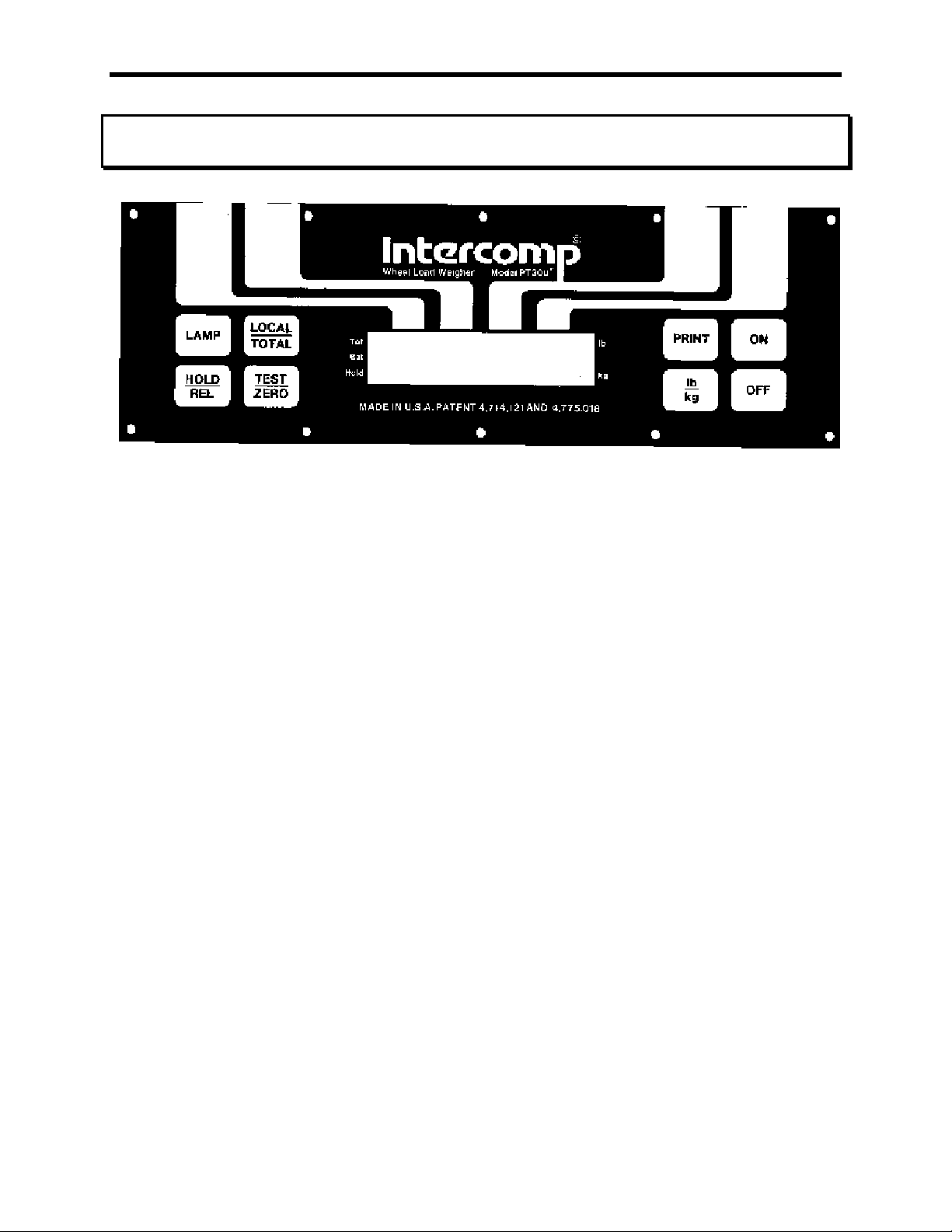
Operations
Diagram 1: PT 300 Keypad and Display
PT300 Users Manual
Rev E, April 1999
ON
Turns the scale on. The scale will test itself by activating all of the segments on the
display and then zero itself. Occasionally the display will show EEEE0, this means
that the scale is seeking zero. The display stays on EEEE0 while the scale is either in
motion or has an unacceptable deadload.
OFF
Turns the scale off.
PRINT
If cabled for a demand output, this button transmits data via a cable to another scale,
printer, display, etc..
lb/kg
Converts the weight on the scale from pounds to kilograms or vice versa. The
indicating bars on the right side of the display indicate which mode the scale is in.
LOCAL/TOTAL
If more than one scale is cabled together, the scales can display the actual weight
they are seeing (local), or the sum total weight of two or more scales (total). The
indicating bar on the upper left side of the display is off when in the local mode, and
on when in the total mode.
Page 6 of 21
Page 7

PT300 Users Manual
Rev E, April 1999
TEST/ZERO
This switch will "test" the display by activating all of its segments. It then zeros the
scale. See the explanation for the ON button.
LAMP
This switch will back light the display for night use. The lamps only stay on while the
button is being pushed.
HOLD/RELEASE
When in the hold mode, the scale will constantly display the highest weight applied to
it. When in the release mode, the scale shows the actual weight upon it. The
indicating bar on the lower left side of the display is on when in the hold mode, and off
when in the release mode.
The indicating bar next to Bat comes on when the batteries are getting low. The
scale will continue to operate correctly for approximately two hours before shutting
itself off.
Page 7 of 21
Page 8

PT300 Users Manual
Rev E, April 1999
Batteries / Charging
This scale can be used while it is charging.
Batteries: 6 - 1.2 volt nicads.
Battery Life: Approximately 5 years. (1000 charge/discharge cycles).
Battery duration between charges: Approximately 8 hours of continuous use
before the low battery indicator comes on, and approximately 2 hours after that before
the scale shuts itself off. Low Batt. indicator comes on when the battery voltage gets
down to approximately 7.3 volts.
Automatic Shutoff: The scale turns itself off when the battery voltage gets down to
approximately 6.3 volts.
Charging Voltage: 11.5 volts - 14.5 volts DC. Protection is provided for accidental
reversal of the charging connections.
Charging Current: Starts at approximately 300mA and drops down to 50mA
after 8 hours.
Charging Time: 8 hours if the batteries are discharged to the point
of turning off the scale.
WARNING: Do not plug the charger in while there are standard alkaline cells
inside. This could result in damage to the batteries and your scale.
Charging the batteries
The batteries can be charged using 120v AC or 11.5V - 14.5V DC. For AC charging
use the plug in transformer provided. Connect the black lead from the charging cable
to the (-) terminal and the red lead to the (+) terminal.
For DC charging, connect the red lead to positive voltage and the black lead to
ground.
Page 8 of 21
Page 9

PT300 Users Manual
Rev E, April 1999
Totalizing and/or Printing
Before you attempt to do either of these, a few terms and definitions must be
understood. These terms only apply to scales that are cabled together.
Master Scale: If more than one scale is being used, the first scale in line is
referred to as the Master Scale. Normally these scales have continuous output,
If you requested a demand output use the print button on this scale when
printing or totalizing.
Slave Scale: If more than one scale is being used, any scale that is not the
master scale is referred to as a Slave Scale.
Master Slave Slave Slave
scale A scale B scale C scale D
Diagram 2: Example of Master/Slave designations
Printer
The master and slave designations are determined by the cable and not the scale itself.
The cable also determines if the scale transmits data on demand (when the print button
is pushed) or continuously. If continuous, the print button doesn't have to be activated
to totalize or print. Please refer to the cabling diagrams
Totalizing
When more than one scale is being used, the last one in line can be used to show the
total weight of all the scales added together. To totalize, turn on the scales in
sequential order starting with the master scale (“scale A") and make sure all of the
slave scales are in the total mode. The indicating bar on the upper left side of the
display is on when in the total mode. This does not mean that the scale is receiving;
only that it is capable of receiving.
If transmitting on demand, press the print button on the master scale and the last
scale in line (slave scale D in the diagram) will show the total weight of all the scales.
Example: Scale A will display the total of A only.
Scale B will display the total of A + B.
Scale C will display the total of A + B + C.
Scale D will display the total of A + B + C + D.
Page 9 of 21
Page 10

PT300 Users Manual
Rev E, April 1999
Printing
Use the print button on the master scale when printing. If more than one scale is
being used, put the slave scale(s) in the total mode. This will allow the printer to print
the total weight of all the scales. The important thing to remember is that the
printer will print whatever is displayed on the last scale in line before the printer.
In addition to the weight, the printer will print a letter that signifies the number of scales
that it printed the weight from.
i.e. The letter A signifies the weight is from one scale. The letter B signifies the weight
is from two scales etc..
Data Interface
Serial ASCII
20 mA current loop, active or passive. (The PT300 supplies the current for active
current loop, and an external current is used for passive current loop. Passive is
preferred for longer battery use between charges.)
1200 Baud
8 data bits
1 start bit
2 stop bits
no parity
M Kg
Transmission Format: A_O_-XXXXXXX._Lb<CR><LF>
Z
Format explanation: A = Scale code (Signifies the scale, could be
A for scale A, B for scale B etc..)
Space
M,O,Z = Error code (M = motion, O = over-capacity,
Z = zero, space = no error)
Space
Minus sign if negative, space if positive.
8 data bits
Space
Pounds/Kilograms
Carriage return
Line feed
Page 10 of 21
Page 11

Error Messages
Ol
Ol
OlOl
Ol
Ol----
OlOl
EEEE0
EEEE0
EEEE0EEEE0
Overload. Reduce load to scale.
Underload. Re-zero scale.
Seeking zero. Wait until reading is displayed. If this error
message stays on, the EEPROM may be damaged. Scale
will require calibration.
PT300 Users Manual
Rev E, April 1999
Page 11 of 21
Page 12

PT300 Users Manual
Rev E, April 1999
Cables
The following diagrams show the different types of cables that can be used with PT 300
scales. Cables can be ordered consisting of 2-6 connectors so you can match the
number of scales your system has. The following diagrams illustrate a 4 scale system.
4 Scale Interconnect
Cabling for 4 scales and a printer with the PT 300 supplying the 20 mA current.
Page 12 of 21
Page 13

4 Scale Charger-Totalizer Combo
PT300 Users Manual
Rev E, April 1999
4 scale totalizer cable with battery charger connection.
Page 13 of 21
Page 14

4 Scale Totalizer to Printer on Demand
PT300 Users Manual
Rev E, April 1999
4 scale totalizing cable including 25 pin D-sub connector for a printer or computer
Page 14 of 21
Page 15

4 Scale PT Charger
PT300 Users Manual
Rev E, April 1999
4 scale battery charging cable
Page 15 of 21
Page 16

PT300 Users Manual
Rev E, April 1999
Current Loop Output to an Intercomp S400 Display:
PT300 Connector Pin Designations:
PT Circular Connector
A: Reserved for future use.
B: - Input
C: Ground (- Charging Voltage)
D: - Output
E: +Charging Voltage
F: + Input
G: Reserved for future use.
H: + Output
View from back (solder)
Page 16 of 21
Page 17

Internal Connector Pin Designations
Plug: 1) +Ex (Summing board)
2) +Sig (Summing board)
3) -Sig (Summing board)
4) -Ex (Summing board)
5) GND (Case and pin C on the I/O connector)
6) +Batt (Battery Clip)
7) +Charging (Pin E of I/O Connector)
8) +Input (Pin F on external connector)
9) -Input (Pin B on external connector)
10) +Output (Pin H on external connector)
11) -Output (Pin D on external connector)
12) Unused
Receptacle:
1) +Ex (PT board)
2) +Sig (PT board)
3) -Sig (PT board)
4) -Ex (PT board)
5) -Batt (GND on PT board)
6) +Batt (PT board)
7) 12V (PT board)
8) +Input (PT board)
9) -Input (PT board)
10) +Output (PT board)
11) -Output (PT board)
12) Unused
PT300 Users Manual
Rev E, April 1999
Page 17 of 21
Page 18

PT300 Users Manual
Rev E, April 1999
WEIGHING PROCEDURES
The PT300 or LP600 can be used separately, in pairs, or in groups of 4, 6, or more.
They can be used to measure a support load, wheel load, axle load, axle group load
or the total weight of a 2 or 3 axle truck in one measuring procedure.
Ideally, all wheels of a vehicle should be measured at the same time in order to avoid
measuring errors due to the suspension system.
If you are not able to weigh the wheels of a double and triple axles simultaneously,
the difference in height must be compensated for by using dummy plates (grids, wood
or rubber plates) of the same height. The wheel load scales are put in front of the
wheels of a vehicle. The driver then drives on the scales/plates and stops within the
active weighing area. To avoid improper weighing which might be caused by wheel or
axle load displacements, the vehicle brakes should be released before reading the
weight values.
COMBINATIONS FOR CORRECT WEIGHING
1. It is recommended to weigh the wheels of one axle at the same time.
2.The dummy plates can be omitted if the scales are embedded in recesses in the
road surface at the same levels as the road surface.
Please see Table 1 on the following page
Page 18 of 21
Page 19

Table 1: Weighing Combinations
PT300 Users Manual
Rev E, April 1999
Page 19 of 21
Page 20

Typical Scale Layouts
PT300 Users Manual
Rev E, April 1999
Notes: Zero key on MASTER scale will tare out all weigh pads that are interconnected.
Read total weight of all scales at READ scale.
Page 20 of 21
Page 21

PT300 Users Manual
Rev E, April 1999
How to reach Intercomp Service
Things to know:
Inform the Service Dept. that the product is a PT300 scale system.
When was the PT300 purchased?
Where was the PT300 purchased?
For Intercomp Service call or fax:
FAX # (763)-476-2613
(763)-476-2531
1-800-328-3336
or fill out Service Support Form at :
www.intercompcompany.com
Copyright Intercomp Company 1999
ALL RIGHTS RESERVED
Page 21 of 21
 Loading...