

Page 1
Installation Manual
Installationshandbuch
Manuel d’installation
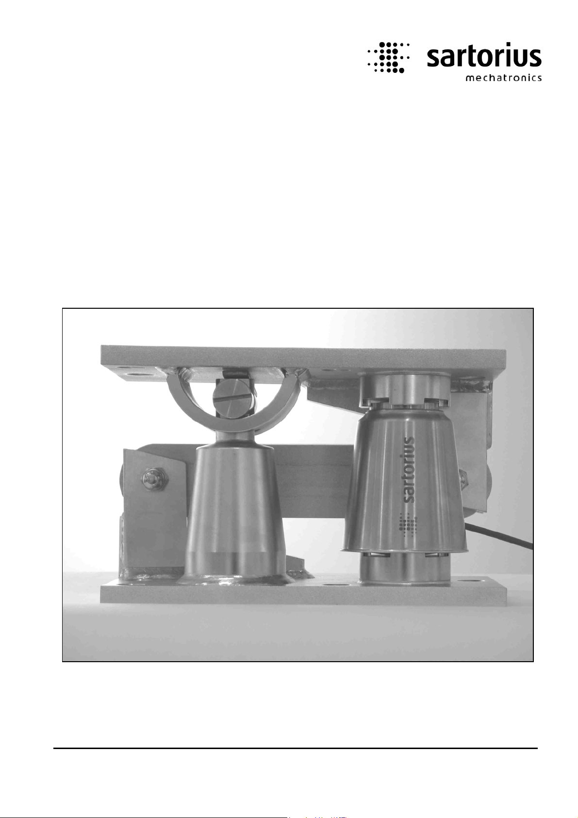
Mounting Kits for Load Cell PR 6202
PR 6002
9499 053 00211 Edition 2 15.12.2010
Sartorius Mechatronics T&H GmbH, Meiendorfer Str. 205, 22145 Hamburg, Germany
Tel:+49.40.67960.303 Fax:+49.40.67960.383
Page 2

Please note
In any correspondence concerning this instrument, please always quote the type number and serial
number as given on the type plate.
Important
As the instrument is an electrical apparatus, it may be operated only by trained personnel.
Maintenance and repairs may only be carried out by qualified personnel.
Bitte beachten
Bei Schriftwechsel über dieses Gerät wird gebeten, die Typennummer und die Seriennummer
anzugeben. Diese befinden sich auf dem Typenschild.
Wichtig
Da das Gerät ein elektrisches Betriebsmittel ist, darf die Bedienung nur durch eingewiesenes
Personal erfolgen. Wartung und Reparatur dürfen nur von geschultem, fach- und sachkundigem
Personal durchgeführt werden.
Noter s.v.p.
Dans votre correspondance et dans vos réclamations se rapportant à cet appareil, veuillez toujours
indiquer le numéro de type et le numéro de série inscrits sur la plaque signalétique.
Important
Comme il s’agit d’un équipement électrique, la maintenance doit être effectuée par du personnel
qualifié. De même, l’entretien et les réparations sont à confier au personnel qualifié.
Page 3

Installation Manual Mounting Kits PR 6002
List of Contents
1 Safety Instructions .........................................................................................................................2
2 Design Recommendations .............................................................................................................2
2.1 Position of Load Cells and Contrainers...............................................................................................2
2.2 Transport Protections ............................................................................................................................... 3
2.3 Internal Lift-off Protection .................................................................................................................... 4
2.4 Rubber Ring for Mounting ..................................................................................................................... 4
3 Technical Data ................................................................................................................................5
3.1 Scope of Delivery.......................................................................................................................................5
3.1.1 PR 6002/00S + 01S................................................................................................................................... 5
3.1.2 PR 6002/02S + 03S................................................................................................................................... 6
3.1.3 PR 6002/04S + 05S................................................................................................................................... 7
3.1.4 PR 6002/10S + 11S................................................................................................................................... 8
3.1.5 PR 6002/20S + 21S................................................................................................................................... 9
3.2 Technical Data...........................................................................................................................................10
3.3 Dimensions.................................................................................................................................................11
3.3.1 PR 6002/02S .............................................................................................................................................11
3.3.2 PR 6002/03S .............................................................................................................................................11
3.3.3 PR 6002/04S .............................................................................................................................................12
3.3.4 PR 6002/05S .............................................................................................................................................12
3.3.5 MaxiFLEXLOCK PR 6002/10S...............................................................................................................13
3.3.6 MaxiFLEXLOCK PR 6002/11S...............................................................................................................14
3.3.7 Maxi FLEXLOCK PR 6002/20S..............................................................................................................15
3.3.8 PR 6002/21S .............................................................................................................................................16
3.4 Load Disk Sets PR 6002/00S, ../01S ....................................................................................................17
4 Installation
4.1 Before the Mounting
................................................................................................................................... 18
..............................................................................................................................18
4.2 Tightening Torques..................................................................................................................................18
4.3 Mounting
4.3.1 PR 6002/02S, ../03S................................................................................................................................19
4.3.2 PR 6002/04S, ../05S, ../10S, ../11S, ../20S, ../21S............................................................................20
....................................................................................................................................................19
5 Check after Installation and Start-Up..................................................................................... 22
6 Spare Parts and Accessories....................................................................................................... 22
Sartorius EN-1
Page 4
Mounting Kits PR 6002 Installation Manual
1 Safety Instructions
The mounting kits PR 6002 must be used only for the weighing applications for which they are intended.
The dimensions of all mounting and structural components must be calculated so that sufficient
overload capacity is ensured for loads which may occur, while taking the relevant standards into
account. In particular, upright weighing objects (vessel etc.) must be safeguarded against the weighing
installation turning over or being shifted, thus eliminating danger to humans, animals or goods even in
the case of a break in a load cell or mounting element.
If soft layers (e.g. from rubber or plastic) for vibration damping or for temperature insulation are
inserted between mounting kit and vessel and/or between mounting kit and supporting construction, a
load equalisation plate must be inserted between soft layer and mounting kit to ensure an even load
distribution on the mounting kit.
Installation and repair work must be carried out only by qualified personnel.
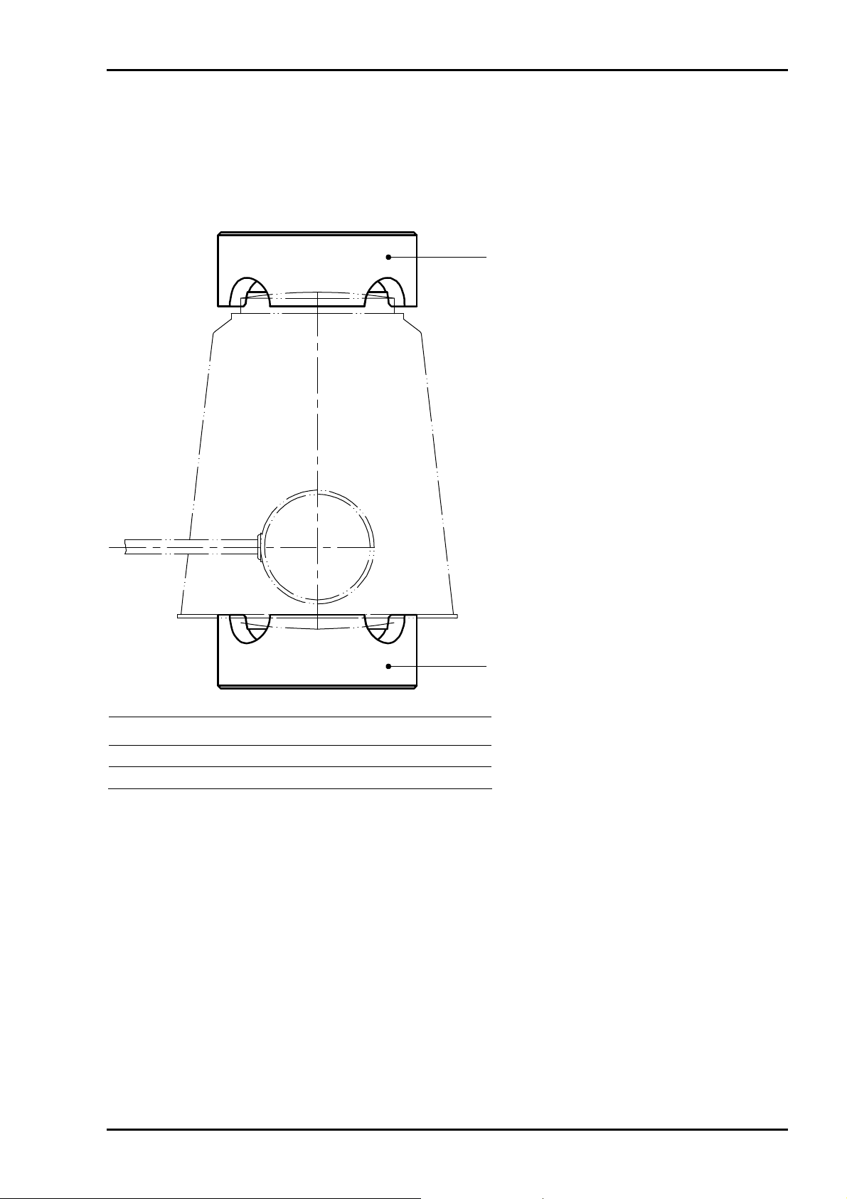
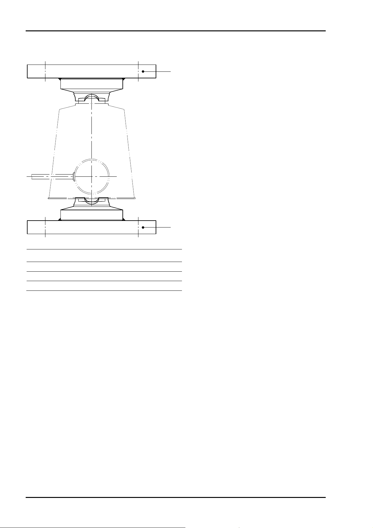
2 Design Recommendations
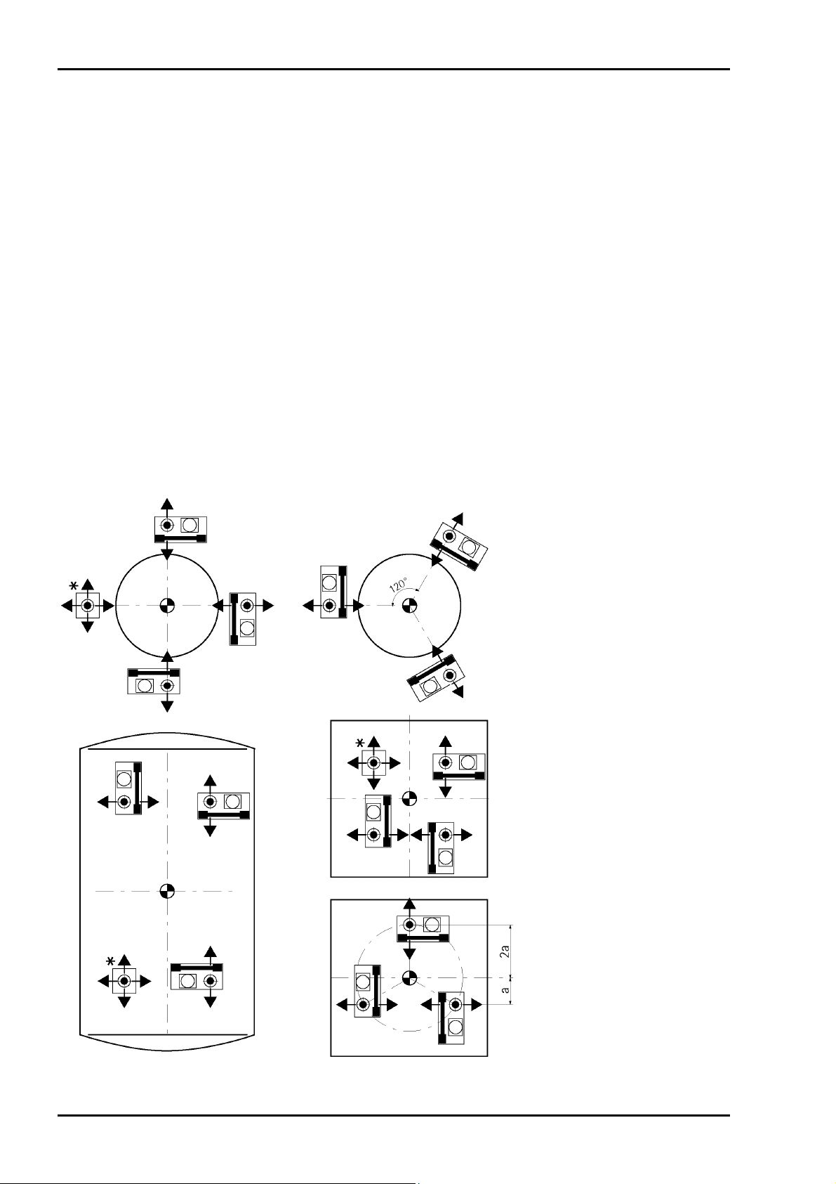
2.1 Position of Load Cells and Contrainers
* do not constrain this position
EN-2 Sartorius
Page 5
Installation Manual Mounting Kits PR 6002
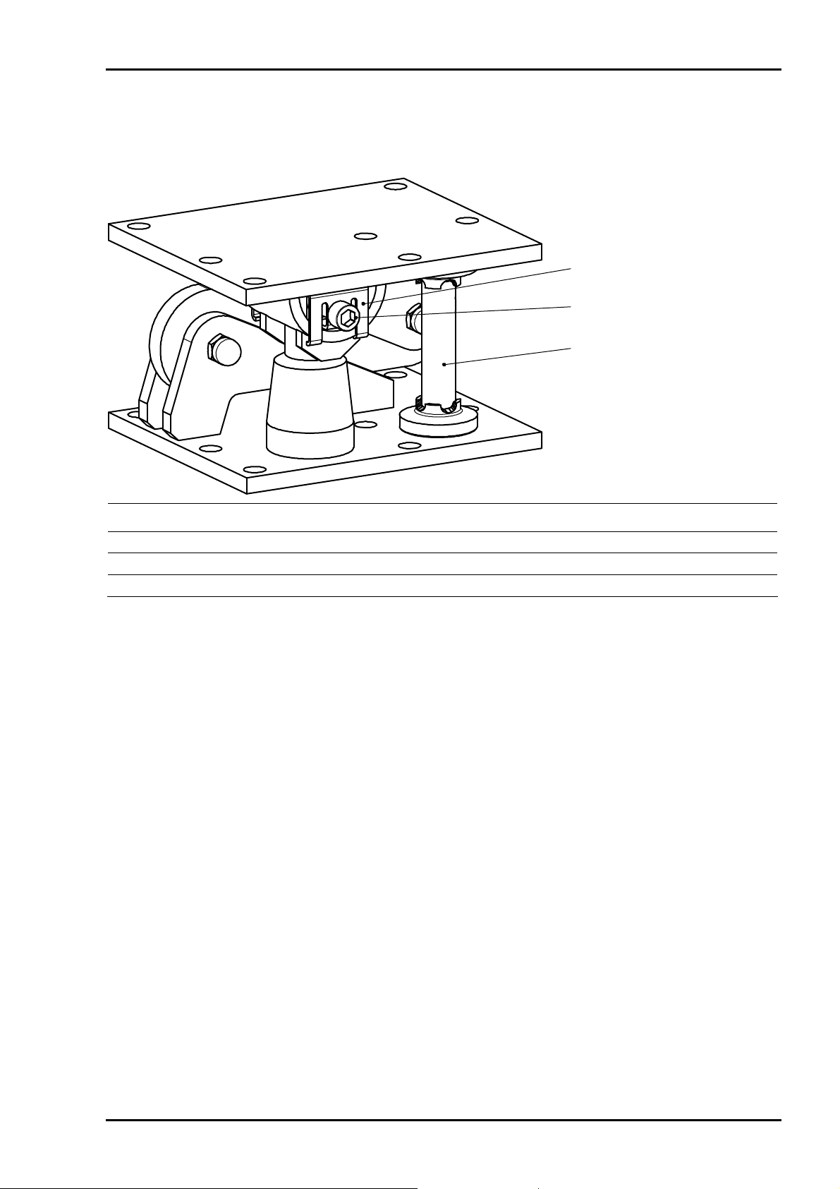
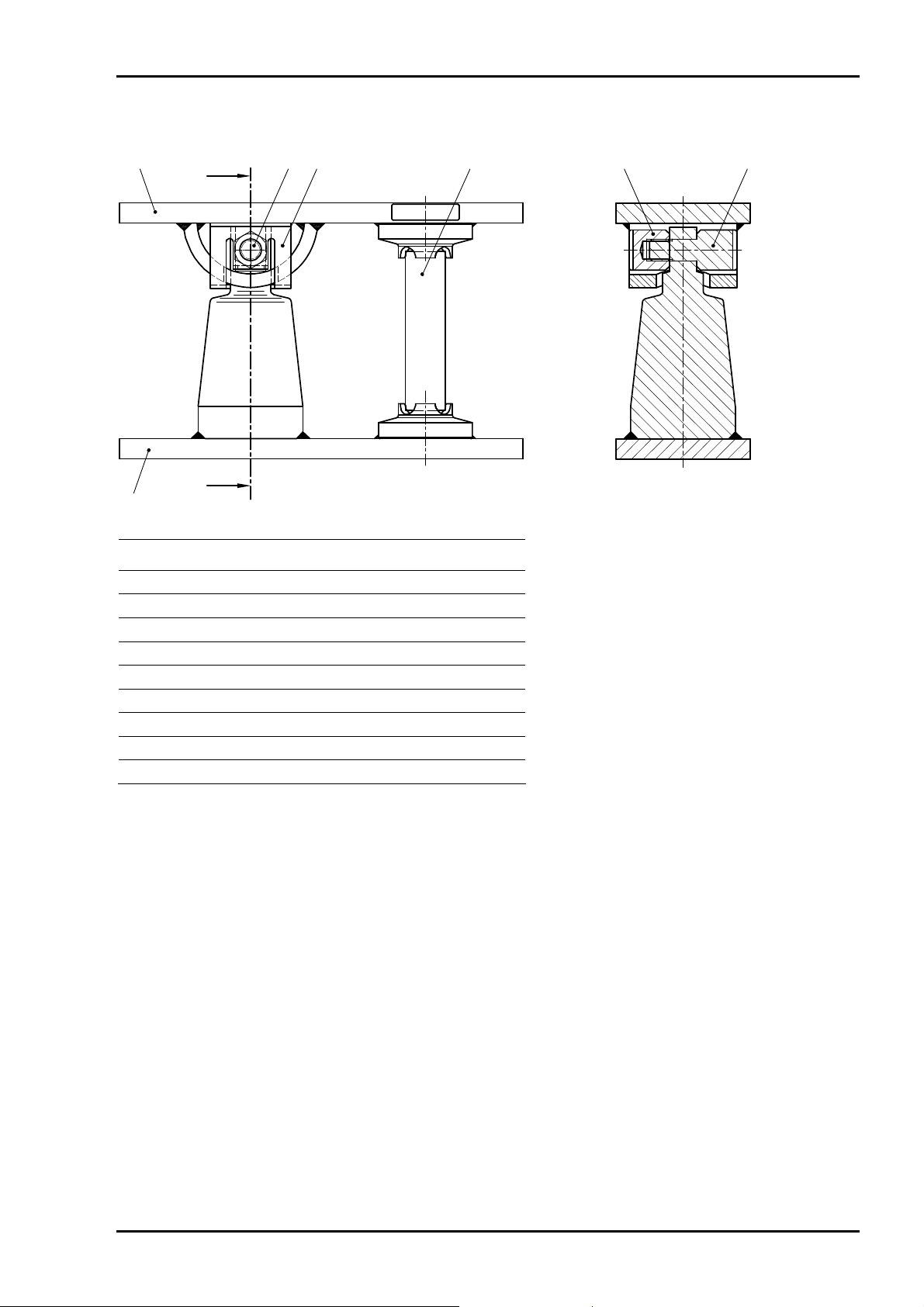
2.2 Transport Protections
The mounting kits are delivered with transport protections.
1
2
3
Pos. Description
1 Bracket (2x)
2 Threaded connection M16
3 Transport bushing (designed as a metal pipe from max. capacity of 25 t)
The transport protections ensure that the mounting height is maintained even without load cell
installed.
After installation of the mounting kit and before mounting the load cell, the transport protections must
be removed.
• Release and remove the threaded connection M16 (2).
• Lift the upper part of the mounting kit and remove the brackets (1) and the transport bushing (3).
Sartorius EN-3
Page 6
Mounting Kits PR 6002 Installation Manual
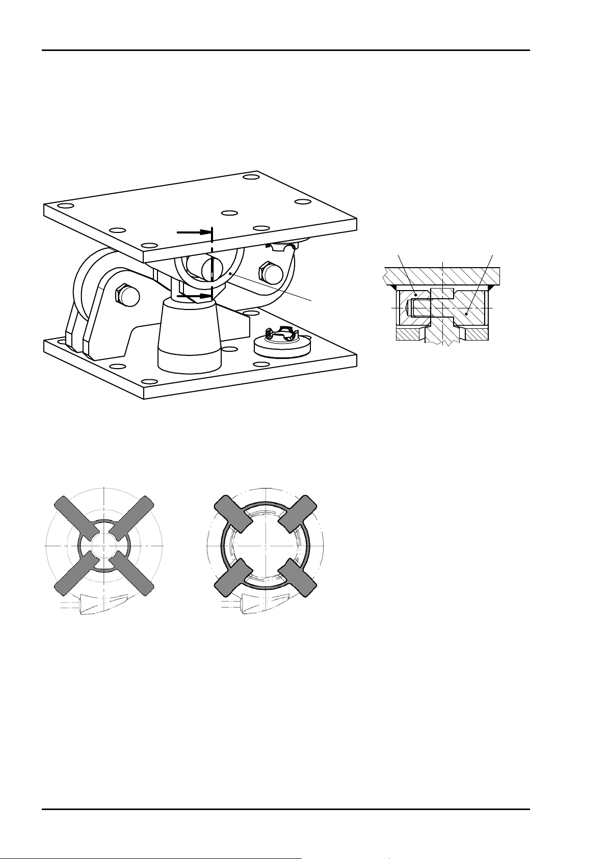
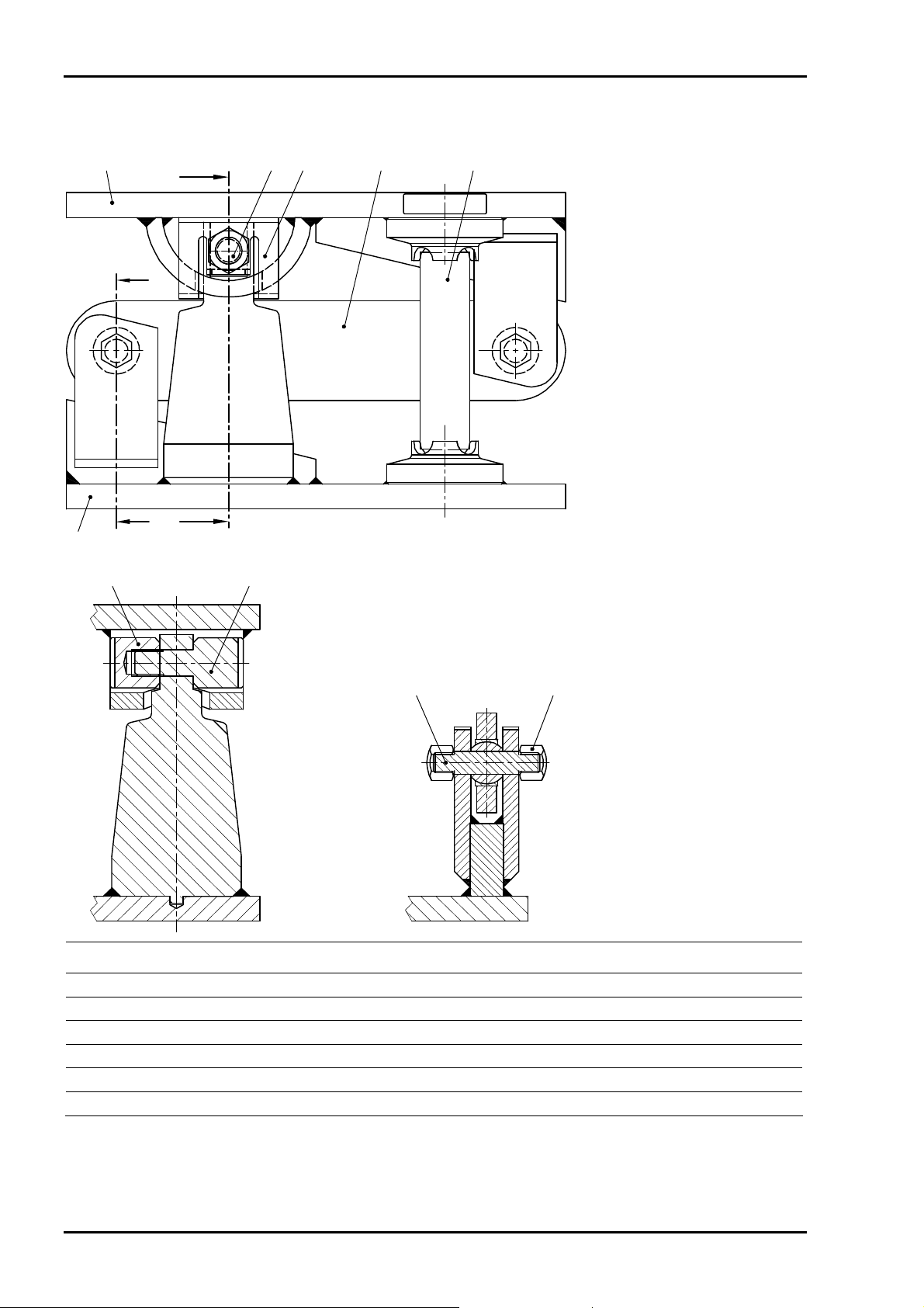
2.3 Internal Lift-off Protection
All mounting kits are equipped with an internal lift-off protection; i.e. no bore holes other than the
mounting holes for the kit are required.
The Lift-off protection is realized by a bolt (2), nut (1) and a retainer (3). Bolt and nut are delivered in a
bag.
21
3
• Mount the lift-off protection after installation/alignment of the load cell.
• Do not turn the slots by more than 30° from the vertical.
2.4 Rubber Ring for Mounting
1…10 t 25…50 t
The rubber ring for mounting is used for vertical installation of the load cell.
• Place the rubber ring on the lower load disk.
• Position the load cell between the load disks.
• Lower the vessel and tighten the mounting screws.
• Pull out the four tabs on the rubber ring by approx. 15 mm so that the rubber ring is removed from
between load disk and load cell.
• Then tear or cut off the rubber ring to remove it completely.
EN-4 Sartorius
Page 7
Installation Manual Mounting Kits PR 6002
3 Technical Data
3.1 Scope of Delivery
3.1.1 PR 6002/00S + 01S
1
Pos. Description
1 Load disk
2 Rubber ring for mounting * (not shown)
* delivered in a bag
1
Sartorius EN-5
Page 8
Mounting Kits PR 6002 Installation Manual
3.1.2 PR 6002/02S + 03S
1
Pos. Description
1 Upper mounting plate
2 Lower mounting plate
3 Rubber ring for mounting * (not shown)
* delivered in a bag
2
EN-6 Sartorius
Page 9
Installation Manual Mounting Kits PR 6002
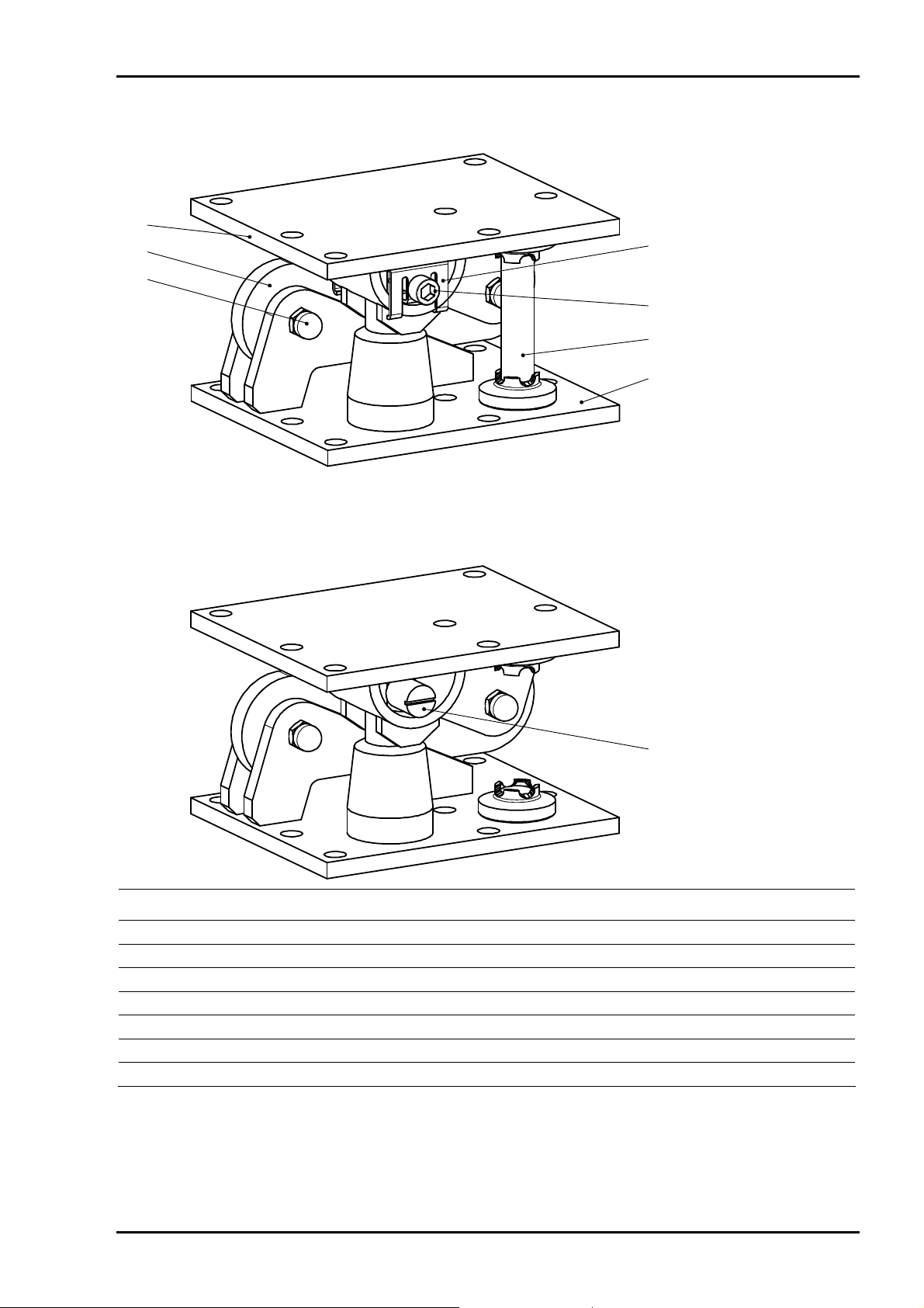
3.1.3 PR 6002/04S + 05S
2, 31 4 765
8
Pos. Description
1 Upper mounting plate
2
Screw M16
×100-A2 *
3 Nut M16-A2 *
4 Transport protection (2x)
5 Transport protection
6 Nut **
7 Bolt **
8 Lower mounting plate
9 Rubber ring for mounting ** (not shown)
* for transport protection (pos. 4)
** delivered in a bag
lift-off protection (6+7) mounted
Abhebesicherung (6+7) montiert
protection contre le basculement (6+7) monté
Sartorius EN-7
Page 10
Mounting Kits PR 6002 Installation Manual
3.1.4 PR 6002/10S + 11S
2, 31 4 65
A
B
11
B
A — A
Pos. Description Pos. Description
1 Upper mounting plate 7 Cap nut M12-A2 (4x)
2
Screw M16
3 Nut M16-A2 * 9 Bolt **
4 Transport protection (2x) 10 Nut **
5 Constrainer 11 Lower mounting plate
6 Transport protection 12 Rubber ring for mounting ** (not shown)
A
910
×100-A2 *
lift-off protection (9+10) mounted
Abhebesicherung (9+10) montiert
protection contre le basculement (9+10) monté
B — B
8 Bolt (2x)
78
* for transport protection (pos. 4)
** delivered in a bag
EN-8 Sartorius
Page 11
Installation Manual Mounting Kits PR 6002
3.1.5 PR 6002/20S + 21S
4
3
1, 2
5, 6
7, 8
9
10
lift-off protection (11+12) mounted
Abhebesicherung (11+12) montiert
protection contre le basculement (11+12) monté
11, 12
Pos. Description Pos. Description
1 Pivot pin (2x) 8 Nut M16-A2 *
2 Cap nut M12-A2 (4x) 9 Transport protection
3 Constrainer 10 Lower mounting plate
4 Upper mounting plate 11 Bolt **
5 Transport protection (2x) 12 Nut **
6 Transport sleeve 13 Rubber ring for mounting ** (not shown)
7
Screw M16
×120-A2 *
* for transport locking devices (pos. 5)
** delivered in a bag
Sartorius EN-9
Page 12

Mounting Kits PR 6002 Installation Manual
3.2 Technical Data
Mounting kit PR 6002/02S PR 6002/03S
Max. capacity of the load cell 1…10 t 25…50 t
Material Stainless steal Stainless steal
Weight, net 4.3 kg 4.6 kg
Mounting kit PR 6002/04S PR 6002/05S
Max. capacity of the load cell 1…10 t 25…50 t
Horizontal destructive force >35 kN >35 kN
Permissible lifting force 25 kN 25 kN
Destructive lifting force >40 kN >40 kN
Max. supporting capacity without load cell 25 kN 25 kN
Max. supporting capacity after delivery
(with transport bushing)
Destructive supporting capacity >100 kN >100 kN
Load cell clearance ±5 mm ±5 mm
Material Stainless steel Stainless steel
Weight, net 17 kg 17 kg
--- 100 kN
Mounting kit PR 6002/10S PR 6002/11S
Max. capacity of the load cell 1…10 t 25…50 t
Permissible lifting force 25 kN 25 kN
Destructive lifting force >40 kN >40 kN
Max. supporting capacity without load cell 25 kN 25 kN
Max. supporting capacity after delivery
(with transport bushing)
Destructive supporting capacity >100 kN >100 kN
Permissible horizontal force in constrainer direction 25 kN 25 kN
Horizontal destructive force in constrainer direction >50 kN >50 kN
Load cell clearance ±5 mm ±5 mm
Material Stainless steel Stainless steel
Weight, net 22.5 kg 22.5 kg
Mounting kit PR 6002/20S PR 6002/21S
Max. capacity of the load cell 1…10 t 25…50 t
Permissible lifting force 25 kN 25 kN
Destructive lifting force >80 kN >80 kN
Max. supporting capacity without load cell 25 kN 25 kN
Max. supporting capacity after delivery
(with transport bushing)
Destructive supporting capacity >100 kN >100 kN
Permissible horizontal force in constrainer direction 50 kN 50 kN
Horizontal destructive force in constrainer direction >100 kN >100 kN
Load cell clearance ±5 mm ±5 mm
Material Stainless steel Stainless steel
Weight, net 34.5 kg 34.5 kg
--- 100 kN
--- 100 kN
EN-10 Sartorius
Page 13
Installation Manual Mounting Kits PR 6002
3.3 Dimensions
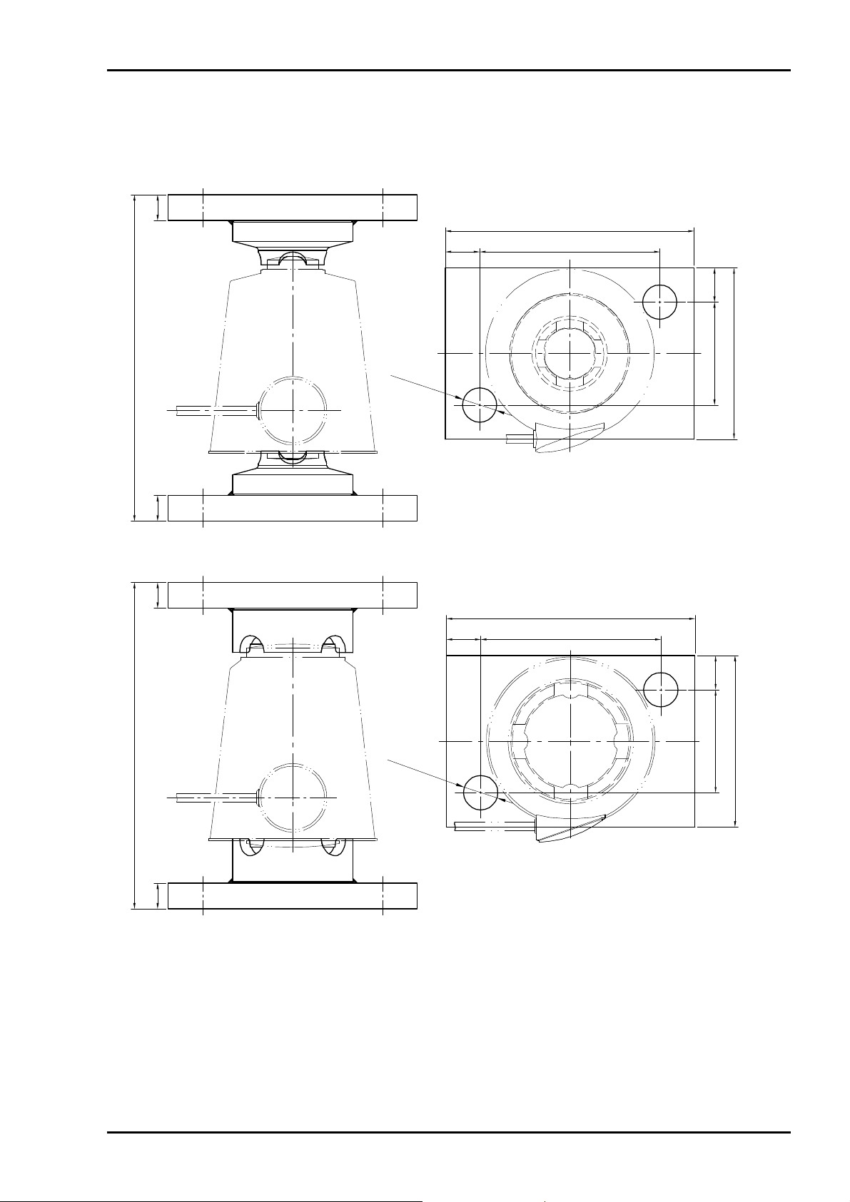
3.3.1 PR 6002/02S
145
20
105
2060
190.5
15 15
3.3.2 PR 6002/03S
190.5
ø
2
0
(
2
x
)
all dimensions in mm
alle Abmessungen in mm
toutes les dimensions en mm
145
20
ø
2
0
(
2
x
)
105
100
2060
100
all dimensions in mm
15 15
alle Abmessungen in mm
toutes les dimensions en mm
Sartorius EN-11
Page 14
Mounting Kits PR 6002 Installation Manual
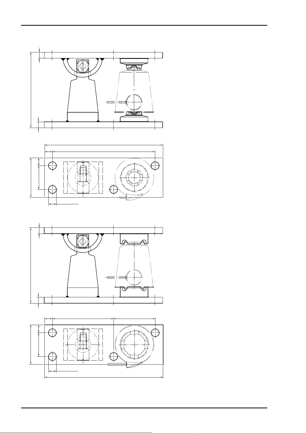
3.3.3 PR 6002/04S
15
190.5
15
300
20 260
2060
100
ø20 (4x)
3.3.4 PR 6002/05S
15
190.5
15
20 155 105
all dimensions in mm
alle Abmessungen in mm
toutes les dimensions en mm
2060
all dimensions in mm
100
ø20 (4x)
300
alle Abmessungen in mm
toutes les dimensions en mm
EN-12 Sartorius
Page 15
Installation Manual Mounting Kits PR 6002
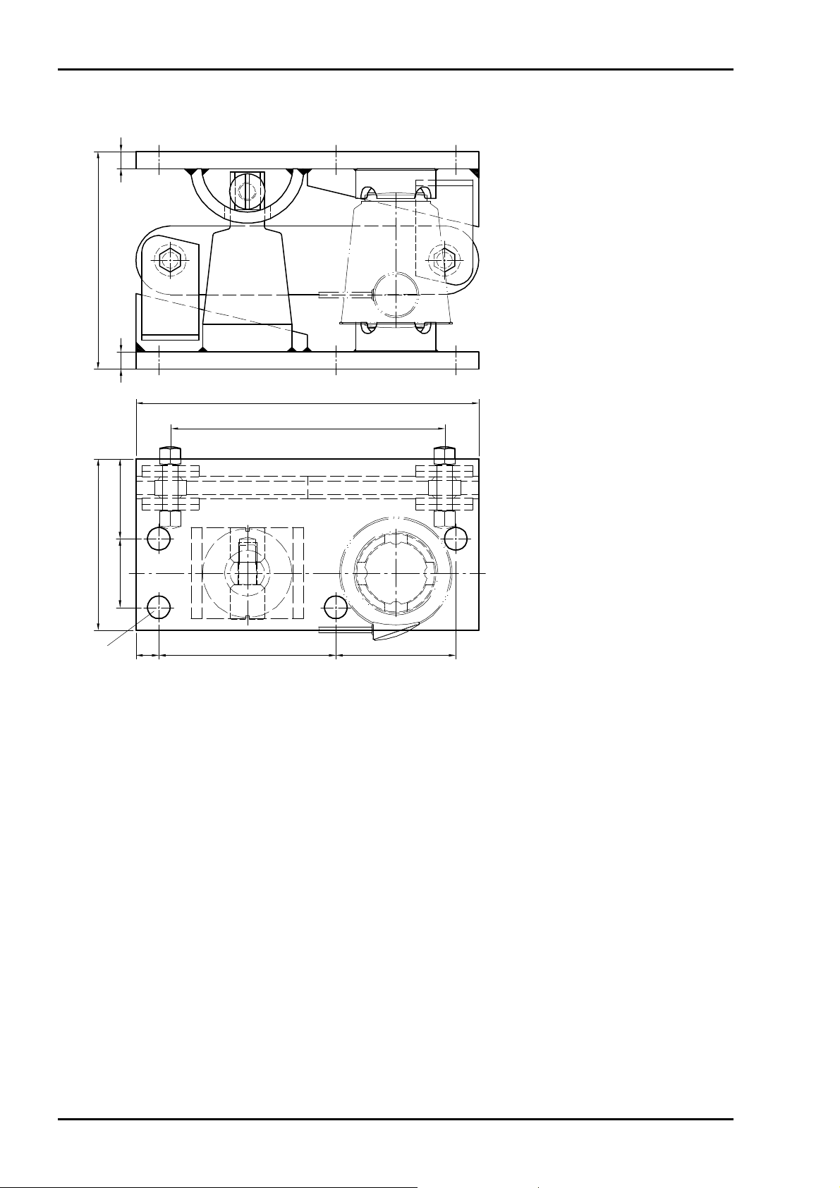
3.3.5 MaxiFLEXLOCK PR 6002/10S
15
190.5
15
300
240
150
ø20 (4x)
7060
all dimensions in mm
alle Abmessungen in mm
toutes les dimensions en mm
20 155 105
Sartorius EN-13
Page 16
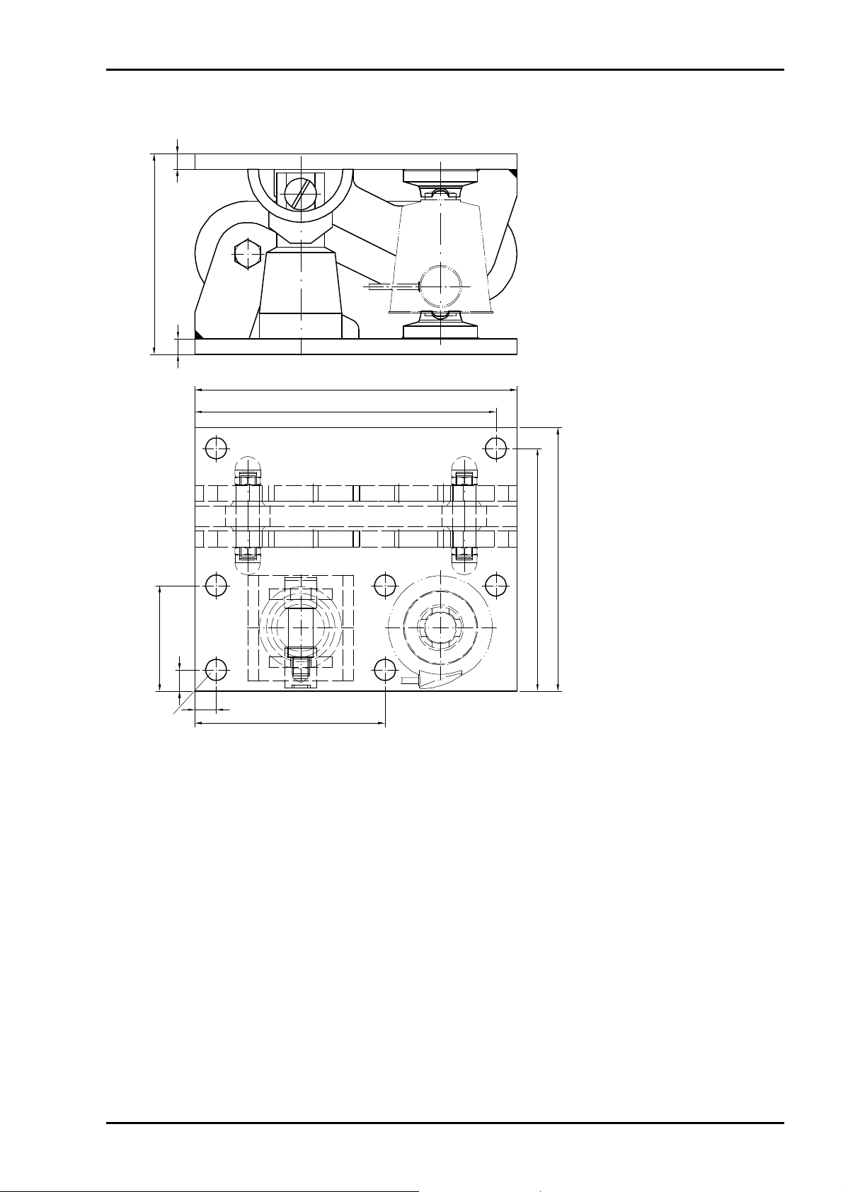
Mounting Kits PR 6002 Installation Manual
3.3.6 MaxiFLEXLOCK PR 6002/11S
15
190.5
15
300
240
150
ø20 (4x)
7060
all dimensions in mm
alle Abmessungen in mm
toutes les dimensions en mm
20 155 105
EN-14 Sartorius
Page 17
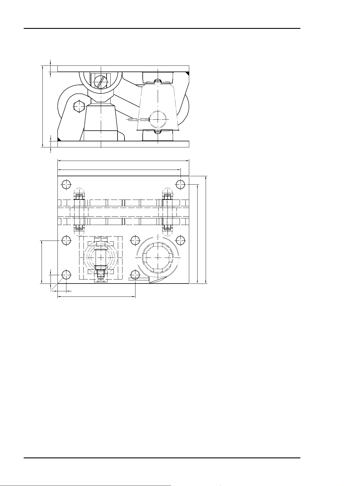
Installation Manual Mounting Kits PR 6002
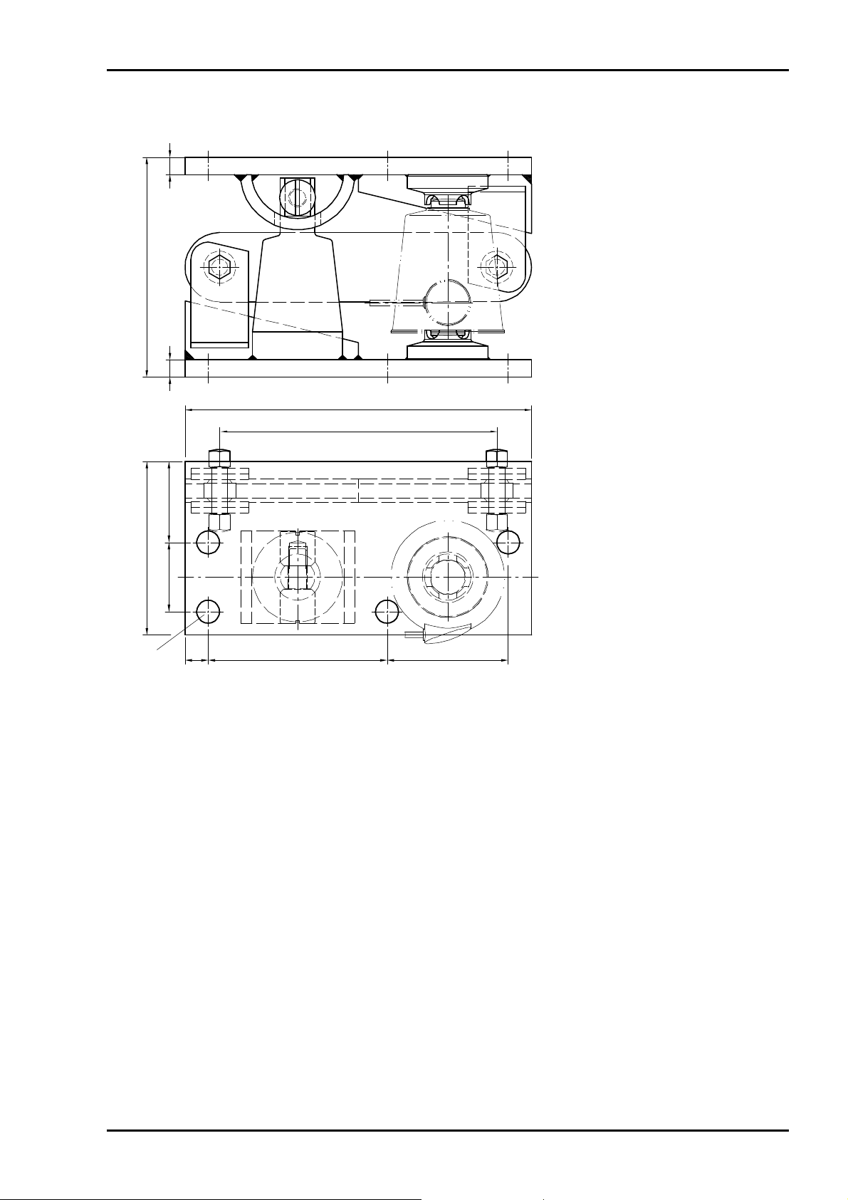
3.3.7 Maxi FLEXLOCK PR 6002/20S
15
190.5
15
305
285
ø20 (7x)
100
20
20
180
250
230
all dimensions in mm
alle Abmessungen in mm
toutes les dimensions en mm
Sartorius EN-15
Page 18
Mounting Kits PR 6002 Installation Manual
3.3.8 PR 6002/21S
15
190.5
15
305
285
ø20 (7x)
100
20
20
180
250
230
all dimensions in mm
alle Abmessungen in mm
toutes les dimensions en mm
EN-16 Sartorius
Page 19
Installation Manual Mounting Kits PR 6002
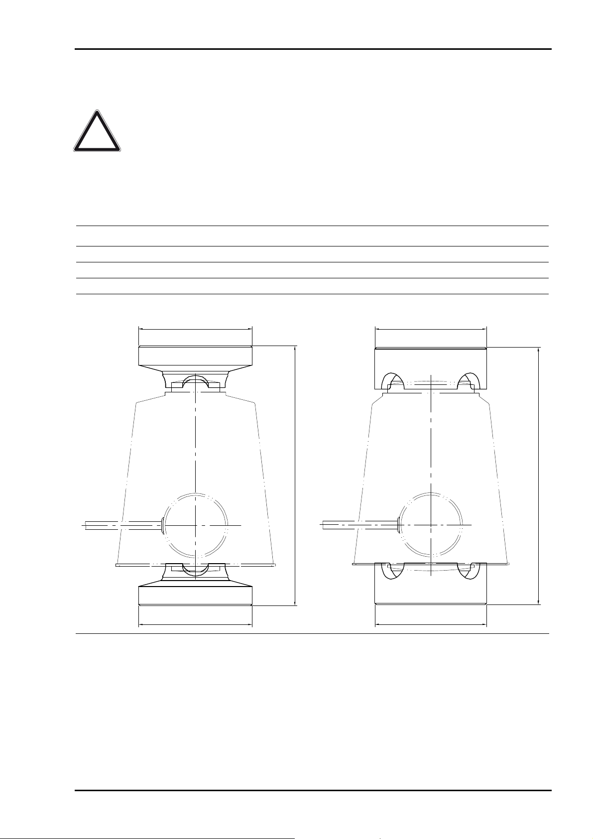
3.4 Load Disk Sets PR 6002/00S, ../01S
Caution!
Material properties and shaping of the load cell and load disk are matching
optimally. Load disks from Sartorius must be used!
The surfaces for the load disks must be horizontal, flat and rigid, and must be able to
withstand the loads encountered during application. If soft layers are inserted
between mounting kit and the rigid adapter, additional load equalization plates
between mounting kit and soft layer must be provided externally.
Type Max. capacity of load cell Material
PR 6002/00S
PR 6002/01S
PR 6002/00S
1…10 t Stainless steel
25…50 t Stainless steel
PR 6002/01S
ø70
160.5
ø70
160.5
ø70
ø70
Sartorius EN-17
Page 20

Mounting Kits PR 6002 Installation Manual
4 Installation
4.1 Before the Mounting
The foundation for the mounting kit must be horizontal (use spirit level), flat and rigid for the loads to
be supported.
The load must be distributed as symmetrical as possible in order not to partially overload the load cells.
The foundations of the mounting kits must be aligned and the supporting surfaces of the weighing
object (e.g. vessel) must mount in parallel.
If soft layers (e.g. from rubber or plastic) for vibration damping or for temperature insulation are
inserted between mounting kit and vessel and / or between mounting kit and supporting construction,
you must take care to insert between soft layer and mounting kit a load equalisation plate to ensure an
even load distribution on the mounting kit.
The version of insulation and equalization plates is application-dependent.
4.2 Tightening Torques
Insert a washer between bolt head and mounting kit. Suitable bolts and washers as well as the
recommended tightening torque are given in the table below.
Mounting kit Bolt
DIN 4014 or DIN 4017
PR 6002/02S
PR 6002/03S
PR 6002/04S
PR 6002/05S
PR 6002/10S
PR 6002/11S
PR 6002/20S
PR 6002/21S
M12-A2-70 13
Washer
DIN 7349
×30×6 A2 70 Nm
Tightening torque
EN-18 Sartorius
Page 21
Installation Manual Mounting Kits PR 6002
4.3 Mounting
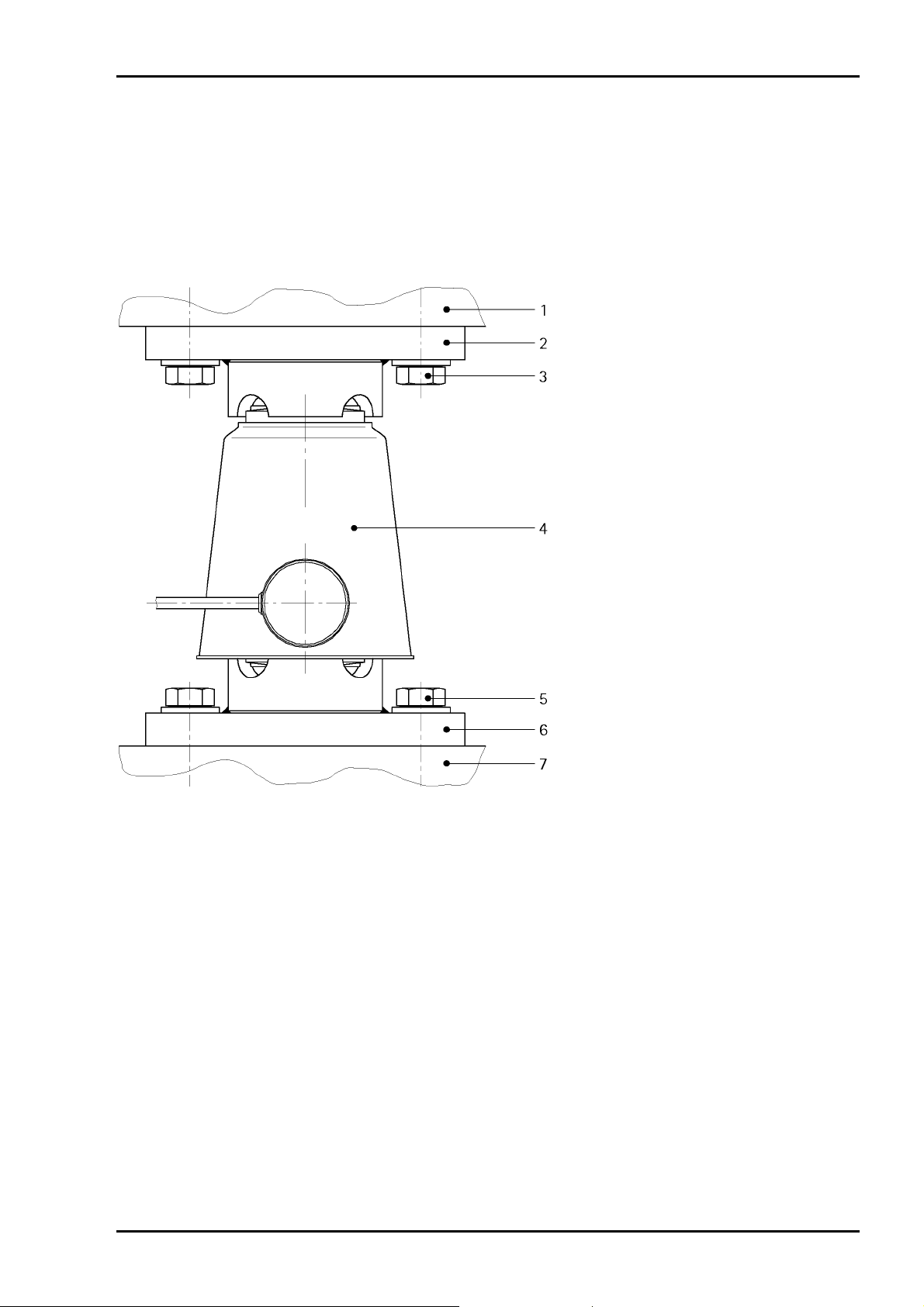
4.3.1 PR 6002/02S, ../03S
Note:
The following steps must be performed at all supporting points of the weighing
object (e.g. vessel)!
• Put the mounting kit on the foundation (7) and tighten the bolts (5) lightly.
• Place the weighing object (1) on the mounting kit and adjust the mounting kit position over the
bore holes.
• Adjust the position of the washers over the bore holes so that the bore holes are covered.
• Tighten the bolts (3) of the upper mounting plate (2) and the bolts (5) of the lower mounting
plate (6) with the recommended tightening moment, see Chapter 4.2.
• Lift the weighing object (1) approx. 5 mm, a required lifting tool.
• Clean the load cell base in both load disks.
• Protect the contact surfaces between load cell/load disks with sufficient grease.
• Position and install the load cell (4) using the rubber ring for mounting, see Chapter 2.4.
• Put the weighing object (1) again on the mounting kit, using a required lifting tool.
• Remove the rubber ring, see Chapter 2.4.
Sartorius EN-19
Page 22

Mounting Kits PR 6002 Installation Manual
4.3.2 PR 6002/04S, ../05S, ../10S, ../11S, ../20S, ../21S
Note:
The following steps must be performed at all supporting points of the weighing
object (e.g. vessel)!
Note:
Note:
• Put the mounting kit on the foundation (6) and tighten the bolts (8) lightly.
• Place the weighing object (1) on the mounting kit and adjust the mounting kit position over the
bore holes.
• Adjust the position of the washers over the bore holes so that the bore holes are covered.
• Tighten the bolts (4) of the upper mounting plate (5) and the bolts (8) of the lower mounting
plate (7) with the recommended tightening moment, see Chapter 4.2.
• Lift the weighing object (1) approx. 5 mm, using a required lifting tool remove the transport
protections (2, 3), see Chapter 2.2.
The mounting kit must be installed so that the access side is easily accessible (in most
installations, this side will face outwards). The load cell is inserted via the access side. The
transport protection can be removed easily.
For PR 6002/10S, ../11S, ../20S, ../21S only:
Adjustment of the constrainer is not necessary.
EN-20 Sartorius
Page 23

Installation Manual Mounting Kits PR 6002
• Clean the load cell base in both load disks.
• Protect the contact surfaces between load cell/load disks with sufficient grease.
• Position and install the load cell (10) using the rubber ring for mounting, see Chapter 2.4.
• Put the weighing object (1) again on the mounting kit, using a required lifting tool.
• Remove the rubber ring, see Chapter 2.4.
• Mount the internal lift-off protection (9), see Chapter 2.3
Sartorius EN-21
Page 24

Mounting Kits PR 6002 Installation Manual
5 Check after Installation and Start-Up
After the installation of all mounting kits and load cells, the correct mounting must be checked. In
particular, force shunts must be avoided.
After mounting also, check
• whether the load cell is inserted without tilt in the mounting kit.
• whether the upper and lower mounting plate is positioned horizontally.
• whether there are vertical space for movement and the required space for thermal expansion.
• whether there are clearance of the constrainer.
The space for movement required for displacement of the object to be weighed due to thermal
expansion, vibration, etc. can be used only if load cell is installed exactly.
To prevent vertical force shunts, all mechanical connections (pipes, cables and bellows) of the object to
be weighed to its surrounding construction must be as flexible as possible. The overall load must be
supported by the load cells.
6 Spare Parts and Accessories
Pos. Description Max. capacity Order number
1 Lift-off protection (stainless steel) 5312 502 18011
2 Rubber ring for mounting 1…10 t 5312 693 98117
3 Rubber ring for mounting 25…50 t 5312 693 98118
EN-22 Sartorius
Page 25

Installationshandbuch Einbausätze PR 6002
Inhaltsverzeichnis
1 Sicherheitshinweise........................................................................................................................2
2 Aufbauempfehlungen ....................................................................................................................2
2.1 Anordnung der Wägezellen und Fesselungen................................................................................... 2
2.2 Transportsicherungen............................................................................................................................... 3
2.3 Interne Abhebesicherung........................................................................................................................4
2.4 Montagehilfe............................................................................................................................................... 4
3 Technische Daten............................................................................................................................5
3.1 Lieferumfang............................................................................................................................................... 5
3.1.1 PR 6002/00S + 01S................................................................................................................................... 5
3.1.2 PR 6002/02S + 03S................................................................................................................................... 6
3.1.3 PR 6002/04S + 05S................................................................................................................................... 7
3.1.4 PR 6002/10S + 11S................................................................................................................................... 8
3.1.5 PR 6002/20S + 21S................................................................................................................................... 9
3.2 Technische Daten.....................................................................................................................................10
3.3 Abmessungen............................................................................................................................................11
3.3.1 PR 6002/02S .............................................................................................................................................11
3.3.2 PR 6002/03S .............................................................................................................................................11
3.3.3 PR 6002/04S .............................................................................................................................................12
3.3.4 PR 6002/05S .............................................................................................................................................12
3.3.5 MaxiFLEXLOCK PR 6002/10S...............................................................................................................13
3.3.6 MaxiFLEXLOCK PR 6002/11S...............................................................................................................14
3.3.7 Maxi FLEXLOCK PR 6002/20S..............................................................................................................15
3.3.8 PR 6002/21S .............................................................................................................................................16
3.4 Druckstücksätze PR 6002/00S, ../01S.................................................................................................17
4 Installation
................................................................................................................................... 18
4.1 Vor der Montage......................................................................................................................................18
4.2 Anzugsmomente ......................................................................................................................................18
4.3 Montage .....................................................................................................................................................19
4.3.1 PR 6002/02S, ../03S................................................................................................................................19
4.3.2 PR 6002/04S, ../05S, ../10S, ../11S, ../20S, ../21S............................................................................20
5 Überprüfung nach dem Einbau und der Inbetriebnahme ..................................................... 22
6 Ersatzteile und Zubehör ............................................................................................................. 22
Sartorius DE-1
Page 26

Einbausätze PR 6002 Installationshandbuch
1 Sicherheitshinweise
Die Einbausätze PR 6002 dürfen nur bestimmungsgemäß für Wägeaufgaben eingesetzt werden. Sämtliche
Einbau- und Konstruktionsteile sind so zu dimensionieren, dass sie unter Beachtung der entsprechenden
Normen eine genügend große Überlastfestigkeit für alle eventuell auftretenden Lasten sicherstellen.
Insbesondere sind stehende Wägeobjekte (Behälter o. ä.) so zu sichern, dass ein Umkippen oder Verschieben
der Wägeinstallation und damit eine Gefährdung von Personen, Tieren oder Gegenständen selbst bei Bruch
einer Wägezelle oder von Einbauteilen auszuschließen ist.
Wenn zwischen Einbausatz und Behälter und/oder zwischen Einbausatz und Unterkonstruktion weiche
Zwischenlagen (z. B. aus Gummi oder Kunststoff) zur Schwingungsdämpfung bzw. zur Temperaturisolation
eingesetzt werden, dann muss zwischen dieser weichen Zwischenlage und dem Einbausatz eine
Lastausgleichsplatte vorgesehen werden, die eine gleichmäßige Lasteinleitung in den Einbausatz sicherstellt.
Installations- und Reparaturarbeiten dürfen nur durch sachkundige/eingewiesene Fachkräfte erfolgen.
2 Aufbauempfehlungen
2.1 Anordnung der Wägezellen und Fesselungen
* diesen Punkt nicht fesseln
DE-2 Sartorius
Page 27

Installationshandbuch Einbausätze PR 6002
2.2 Transportsicherungen
Die Einbausätze werden mit Transportsicherungen ausgeliefert.
1
2
3
Pos. Bezeichnung
1 Lasche (2x)
2 Schraubverbindung M16
3 Transporthülse (ab Nennlast 25 t als Metallrohr ausgeführt)
Die Transportsicherungen stellen sicher, dass die Einbauhöhe auch ohne Wägezelle eingehalten wird.
Nach der Montage des Einbausatzes und vor der Montage der Wägezelle sind die Transportsicherungen zu
entfernen.
• Gewindeverbindung M16 (2) lösen und entfernen.
• Den oberen Teil des Einbausatzes anheben und die Laschen (1) und die Transporthülse (3) entfernen.
Sartorius DE-3
Page 28

Einbausätze PR 6002 Installationshandbuch
2.3 Interne Abhebesicherung
Alle Einbausätze sind mit einer internen Abhebesicherung ausgestattet; das heißt, es sind außer den
Befestigungslöchern keine zusätzlichen Bohrungen erforderlich.
Die Abhebesicherung wird durch eine Schraube (2), eine Mutter (1) und einen Haltebogen (3) realisiert.
Schraube und Mutter liegen dem Einbausatz bei.
21
3
• Nach dem Einbau/Ausrichten der Wägezelle die Abhebesicherung montieren.
• Schlitze nicht mehr als 30° aus der Senkrechten drehen.
2.4 Montagehilfe
1…10 t 25…50 t
Die Montagehilfe dient zum senkrechten Einbau der Wägezelle.
• Montagehilfe auf das untere Druckstück legen.
• Wägezelle zwischen den Druckstücken positionieren.
• Behälter absenken und Montageschrauben anziehen.
• Alle Laschen der Einbauhilfe zunächst ca. 15 mm herausziehen, so dass die Einbauhilfe zwischen
Druckstück und Wägezelle entfernt wird.
• Anschließend die Einbauhilfe durch Reißen oder Schneiden auftrennen und vollständig entfernen.
DE-4 Sartorius
Page 29

Installationshandbuch Einbausätze PR 6002
3 Technische Daten
3.1 Lieferumfang
3.1.1 PR 6002/00S + 01S
1
Pos. Bezeichnung
1 Druckstück
2 Montagehilfe * (nicht abgebildet)
* in einem Beutel mitgeliefert
1
Sartorius DE-5
Page 30

Einbausätze PR 6002 Installationshandbuch
3.1.2 PR 6002/02S + 03S
1
Pos. Bezeichnung
1 Obere Montageplatte
2 Untere Montageplatte
3 Montagehilfe * (nicht abgebildet)
* in einem Beutel mitgeliefert
2
DE-6 Sartorius
Page 31

Installationshandbuch Einbausätze PR 6002
3.1.3 PR 6002/04S + 05S
2, 31 4 765
8
Pos. Bezeichnung
1 Obere Montageplatte
2
Schraube M16
×100-A2 *
3 Mutter M16-A2 *
4 Transportsicherung (2x)
5 Transportsicherung
6 Mutter **
7 Schraube **
8 Untere Montageplatte
9 Montagehilfe ** (nicht abgebildet)
* für Transportsicherungen (Pos. 4)
** in einem Beutel mitgeliefert
lift-off protection (6+7) mounted
Abhebesicherung (6+7) montiert
protection contre le basculement (6+7) monté
Sartorius DE-7
Page 32

Einbausätze PR 6002 Installationshandbuch
3.1.4 PR 6002/10S + 11S
2, 31 4 65
A
B
11
B
A — A
Pos. Bezeichnung Pos. Bezeichnung
1 Obere Montageplatte 7 Hutmutter M12-A2 (4x)
2
Schraube M16
3 Mutter M16-A2 * 9 Schraube **
4 Transportsicherung (2x) 10 Mutter **
5 Lenker 11 Untere Montageplatte
6 Transportsicherung 12 Montagehilfe ** (nicht abgebildet)
A
910
lift-off protection (9+10) mounted
Abhebesicherung (9+10) montiert
protection contre le basculement (9+10) monté
×100-A2 *
B — B
8 Bolzen (2x)
78
* für Transportsicherungen (Pos. 4)
** in einem Beutel mitgeliefert
DE-8 Sartorius
Page 33

Installationshandbuch Einbausätze PR 6002
3.1.5 PR 6002/20S + 21S
4
3
1, 2
5, 6
7, 8
9
10
lift-off protection (11+12) mounted
Abhebesicherung (11+12) montiert
protection contre le basculement (11+12) monté
11, 12
Pos. Bezeichnung Pos. Bezeichnung
1 Achse (2x) 8 Mutter M16-A2 *
2 Hutmutter M12-A2 (4x) 9 Transportsicherung
3 Lenker 10 Untere Montageplatte
4 Obere Montageplatte 11 Schraube **
5 Transportsicherung (2x) 12 Mutter **
6 Transporthülse 13 Montagehilfe ** (nicht abgebildet)
7
Schraube M16
×120-A2 *
* für Transportsicherungen (Pos. 5)
** in einem Beutel mitgeliefert
Sartorius DE-9
Page 34

Einbausätze PR 6002 Installationshandbuch
3.2 Technische Daten
Einbausatz PR 6002/02S PR 6002/03S
Nennlast der Wägezelle 1…10 t 25…50 t
Material Edelstahl Edelstahl
Gewicht, netto 4,3 kg 4,6 kg
Einbausatz PR 6002/04S PR 6002/05S
Nennlast der Wägezelle 1…10 t 25…50 t
Horizontale Bruchkraft >35 kN >35 kN
Zulässige Abhebekraft 25 kN 25 kN
Bruchlast Abhebekraft >40 kN >40 kN
Max. Tragkraft ohne Wägezelle 25 kN 25 kN
Max. Tragkraft bei Anlieferung (mit Transporthülse) --- 100 kN
Bruchlast Tragkraft >100 kN >100 kN
Spiel der Wägezelle ±5 mm ±5 mm
Material Edelstahl Edelstahl
Gewicht, netto 17 kg 17 kg
Einbausatz PR 6002/10S PR 6002/11S
Nennlast der Wägezelle 1…10 t 25…50 t
Zulässige Abhebekraft 25 kN 25 kN
Bruchlast Abhebekraft >40 kN >40 kN
Max. Tragkraft ohne Wägezelle 25 kN 25 kN
Max. Tragkraft bei Anlieferung (mit Transporthülse) --- 100 kN
Bruchlast Tragkraft >100 kN >100 kN
Zulässige Horizontalkraft in Lenkerrichtung 25 kN 25 kN
Bruchlast Horizontal in Lenkerrichtung >50 kN >50 kN
Spiel der Wägezelle ±5 mm ±5 mm
Material Edelstahl Edelstahl
Gewicht, netto 22,5 kg 22,5 kg
Einbausatz PR 6002/20S PR 6002/21S
Nennlast der Wägezelle 1…10 t 25…50 t
Zulässige Abhebekraft 25 kN 25 kN
Bruchlast Abhebekraft >80 kN >80 kN
Max. Tragkraft ohne Wägezelle 25 kN 25 kN
Max. Tragkraft bei Anlieferung (mit Transporthülse) --- 100 kN
Bruchlast Tragkraft >100 kN >100 kN
Zulässige Horizontalkraft in Lenkerrichtung 50 kN 50 kN
Bruchlast Horizontal in Lenkerrichtung >100 kN >100 kN
Spiel der Wägezelle ±5 mm ±5 mm
Material Edelstahl Edelstahl
Gewicht, netto 34,5 kg 34,5 kg
DE-10 Sartorius
Page 35

Installationshandbuch Einbausätze PR 6002
3.3 Abmessungen
3.3.1 PR 6002/02S
145
20
105
2060
190.5
15 15
3.3.2 PR 6002/03S
190.5
ø
2
0
(
2
x
)
all dimensions in mm
alle Abmessungen in mm
toutes les dimensions en mm
145
20
ø
2
0
(
2
x
)
105
100
2060
100
all dimensions in mm
15 15
alle Abmessungen in mm
toutes les dimensions en mm
Sartorius DE-11
Page 36

Einbausätze PR 6002 Installationshandbuch
3.3.3 PR 6002/04S
15
190.5
15
300
20 260
2060
100
ø20 (4x)
3.3.4 PR 6002/05S
15
190.5
15
20 155 105
all dimensions in mm
alle Abmessungen in mm
toutes les dimensions en mm
2060
all dimensions in mm
100
ø20 (4x)
300
alle Abmessungen in mm
toutes les dimensions en mm
DE-12 Sartorius
Page 37

Installationshandbuch Einbausätze PR 6002
3.3.5 MaxiFLEXLOCK PR 6002/10S
15
190.5
15
300
240
150
ø20 (4x)
7060
all dimensions in mm
alle Abmessungen in mm
toutes les dimensions en mm
20 155 105
Sartorius DE-13
Page 38

Einbausätze PR 6002 Installationshandbuch
3.3.6 MaxiFLEXLOCK PR 6002/11S
15
190.5
15
300
240
150
ø20 (4x)
7060
all dimensions in mm
alle Abmessungen in mm
toutes les dimensions en mm
20 155 105
DE-14 Sartorius
Page 39

Installationshandbuch Einbausätze PR 6002
3.3.7 Maxi FLEXLOCK PR 6002/20S
15
190.5
15
305
285
ø20 (7x)
100
20
20
180
250
230
all dimensions in mm
alle Abmessungen in mm
toutes les dimensions en mm
Sartorius DE-15
Page 40

Einbausätze PR 6002 Installationshandbuch
3.3.8 PR 6002/21S
15
190.5
15
305
285
ø20 (7x)
100
20
20
180
250
230
all dimensions in mm
alle Abmessungen in mm
toutes les dimensions en mm
DE-16 Sartorius
Page 41

Installationshandbuch Einbausätze PR 6002
3.4 Druckstücksätze PR 6002/00S, ../01S
Achtung!
Materialeigenschaften und Formgebung der Wägezellen und Druckstücke sind
optimal aufeinander abgestimmt. Unbedingt Druckstücke von Sartorius verwenden!
Die Flächen für die Druckstücke müssen waagerecht, eben und unnachgiebig sein. Sie
müssen die entstehenden Drucklasten aufnehmen können. Wenn weiche
Zwischenlagen vorhanden sind, dann sind extern Lastverteilungsplatten vorzusehen!
Typ Nennlast der Wägezelle Material
PR 6002/00S
PR 6002/01S
PR 6002/00S
1…10 t Edelstahl
25…50 t Edelstahl
PR 6002/01S
ø70
160.5
ø70
160.5
ø70
ø70
Sartorius DE-17
Page 42

Einbausätze PR 6002 Installationshandbuch
4 Installation
4.1 Vor der Montage
Das Fundament für den Einbausatz muss waagerecht (Wasserwaage benutzen), eben und unnachgiebig für
die vorgesehenen Lasten sein.
Die Belastung muss möglichst gleichmäßig verteilt werden, um die Wägezellen nicht partiell zu überlasten.
Die Fundamente der Einbausätze müssen sich auf gleicher Höhe befinden, und die Auflageflächen des
Wägeobjekts (z. B. Behälter) müssen parallel angeordnet sein.
Wenn zwischen Einbausatz und Behälter und/oder zwischen Einbausatz und Unterkonstruktion weiche
Zwischenlagen (z. B. aus Gummi oder Kunststoff) zur Schwingungsdämpfung bzw. zur Temperaturisolation
eingesetzt werden, dann muss zwischen dieser weichen Zwischenlage und dem Einbausatz eine
Lastausgleichsplatte vorgesehen werden, die eine gleichmäßige Lasteinleitung in den Einbausatz sicherstellt.
Die Ausführung der Isolations- und Ausgleichsplatten ist applikationsabhängig.
4.2 Anzugsmomente
Zwischen Schraubenkopf und Platte muss eine Scheibe sein. Die passenden Schrauben und Scheiben sowie
das empfohlene Anzugsmoment kann der folgenden Tabelle entnommen werden.
Einbausatz Schraube
DIN 4014 oder DIN 4017
PR 6002/02S
PR 6002/03S
PR 6002/04S
PR 6002/05S
PR 6002/10S
PR 6002/11S
PR 6002/20S
PR 6002/21S
M12-A2-70 13
Scheibe
DIN 7349
×30×6 A2 70 Nm
Anzugsmoment
DE-18 Sartorius
Page 43

Installationshandbuch Einbausätze PR 6002
4.3 Montage
4.3.1 PR 6002/02S, ../03S
Hinweis:
Die folgenden Arbeitsschritte müssen an allen Auflagepunkten des
Wägeobjektes (z. B. Behälter) durchgeführt werden!
• Einbausatz auf das Fundament (7) stellen und die Schrauben (5) leicht anziehen.
• Wägeobjekt (1) auf den Einbausatz stellen und über die Bohrungen ausrichten.
• Die Scheiben so über die Bohrungen ausrichten, dass diese abgedeckt sind.
• Die Schrauben (3) der oberen Montageplatte (2) und die Schrauben (5) der unteren Montageplatte (6)
mit empfohlenem Moment festziehen, siehe Kapitel 4.2.
• Wägeobjekt (1) mit entsprechender Hebevorrichtung ca. 5 mm anheben.
• Wägezellensitz in den beiden Druckstücken reinigen.
• Kontaktflächen zwischen Wägezelle/Druckstücke mit ausreichend Fett versehen.
• Wägezelle (4) mit Montagehilfe positionieren und einbauen, siehe Kapitel 2.4.
• Wägeobjekt (1) mit entsprechender Hebevorrichtung wieder auf den Einbausatz absenken.
• Montagehilfe entfernen, siehe Kapitel 2.4.
Sartorius DE-19
Page 44

Einbausätze PR 6002 Installationshandbuch
4.3.2 PR 6002/04S, ../05S, ../10S, ../11S, ../20S, ../21S
Hinweis:
Die folgenden Arbeitsschritte müssen an allen Auflagepunkten des
Wägeobjektes (z. B. Behälter) durchgeführt werden!
Hinweis:
Hinweis:
• Einbausatz auf das Fundament (6) stellen und die Schrauben (8) leicht anziehen.
• Wägeobjekt (1) auf den Einbausatz stellen und über die Bohrungen ausrichten.
• Die Scheiben so über die Bohrungen ausrichten, dass diese abgedeckt sind.
• Die Schrauben (4) der oberen Montageplatte (5) und die Schrauben (8) der unteren Montageplatte (7)
mit empfohlenem Moment festziehen, siehe Kapitel 4.2.
• Wägeobjekt (1) mit entsprechender Hebevorrichtung ca. 5 mm anheben und die
Transportsicherungen (2, 3) entfernen, siehe Kapitel 2.2.
Der Einbausatz ist so zu installieren, dass die Bedienseite leicht zugänglich ist (in den
meisten Fällen wird sie nach außen zeigen). Von der Bedienseite aus ist die Wägezelle
zugänglich. Die Transportsicherung kann leicht entfernt werden.
Nur für PR 6002/10S, ../11S, ../20S, ../21S:
Der Lenker muss nicht eingestellt werden!
DE-20 Sartorius
Page 45

Installationshandbuch Einbausätze PR 6002
• Wägezellensitz in den beiden Druckstücken reinigen.
• Kontaktflächen zwischen Wägezelle/Druckstücke mit ausreichend Fett versehen.
• Wägezelle (10) mit Montagehilfe positionieren und einbauen, siehe Kapitel 2.4.
• Wägeobjekt (1) mit entsprechender Hebevorrichtung wieder auf den Einbausatz absenken.
• Montagehilfe entfernen, siehe Kapitel 2.4.
• Interne Abhebesicherung (9) montieren, siehe Kapitel 2.3.
Sartorius DE-21
Page 46

Einbausätze PR 6002 Installationshandbuch
5 Überprüfung nach dem Einbau und der Inbetriebnahme
Wenn alle Einbausätze installiert sind, ist der ordnungsgemäße Einbau zu überprüfen. Insbesondere müssen
Kraftnebenschlüsse vermieden werden.
Weiterhin ist nach dem Einbau und der Inbetriebnahme zu überprüfen,
• ob die Wägezelle senkrecht und unverkantet im Einbausatz eingesetzt ist.
• ob obere und untere Montageplatte waagerecht montiert sind.
• ob vertikale Bewegungsfreiheit und das erforderliche Spiel für thermische Dehnung gegeben sind.
• ob Freigängigkeit der Lenker vorhanden ist.
Nur bei exakt eingebauter Wägezelle kann die Bewegungsfreiheit, die für Verlagerungen des Messobjekts
durch thermische Dehnung, Vibration o. ä. erforderlich ist, ohne Einschränkung der Messgenauigkeit genutzt
werden.
Zur Vermeidung von Kraftnebenschlüssen sind alle Zu- und Ableitungen (Schläuche, Rohre, Kabel) so flexibel
wie möglich an das Messobjekt zu koppeln. Die gesamte Last muss von den Wägezellen getragen werden.
6 Ersatzteile und Zubehör
Pos. Bezeichnung Laststufen Bestellnummer
1 Abhebesicherung (Edelstahl) 5312 502 18011
2 Montagehilfe 1…10 t 5312 693 98117
3 Montagehilfe 25…50 t 5312 693 98118
DE-22 Sartorius
Page 47

Manuel d’installation Kits de montage PR 6002
Sommaire
1 Consignes de sécurité ....................................................................................................................2
2 Recommandations d’installation..................................................................................................2
2.1 Disposition des capteurs dans différents cas .................................................................................... 2
2.2 Sécurités de transport..............................................................................................................................3
2.3 Protection interne contre le basculement.........................................................................................4
2.4 Anneau d’aide de montage..................................................................................................................... 4
3 Caractéristiques techniques..........................................................................................................5
3.1 Contenu de la livraison............................................................................................................................5
3.1.1 PR 6002/00S + 01S................................................................................................................................... 5
3.1.2 PR 6002/02S + 03S................................................................................................................................... 6
3.1.3 PR 6002/04S + 05S................................................................................................................................... 7
3.1.4 PR 6002/10S + 11S................................................................................................................................... 8
3.1.5 PR 6002/20S + 21S................................................................................................................................... 9
3.2 Caractéristiques techniques..................................................................................................................10
3.3 Dimensions.................................................................................................................................................11
3.3.1 PR 6002/02S .............................................................................................................................................11
3.3.2 PR 6002/03S .............................................................................................................................................11
3.3.3 PR 6002/04S .............................................................................................................................................12
3.3.4 PR 6002/05S .............................................................................................................................................12
3.3.5 MaxiFLEXLOCK PR 6002/10S...............................................................................................................13
3.3.6 MaxiFLEXLOCK PR 6002/11S...............................................................................................................14
3.3.7 Maxi FLEXLOCK PR 6002/20S..............................................................................................................15
3.3.8 PR 6002/21S .............................................................................................................................................16
3.4 Load Disk Sets PR 6002/00S, ../01S ....................................................................................................17
4 Installation
................................................................................................................................... 18
4.1 Avant le montage ....................................................................................................................................18
4.2 Couples de torsion...................................................................................................................................18
4.3 Montage .....................................................................................................................................................19
4.3.1 PR 6002/02S, ../03S................................................................................................................................19
4.3.2 PR 6002/04S, ../05S, ../10S, ../11S, ../20S, ../21S............................................................................20
5 Contrôle après l’installation et la mise en service.................................................................. 22
6 Pièces de rechange et accessoires............................................................................................. 22
Sartorius FR-1
Page 48

Kits de montage PR 6002 Manuel d’installation
1 Consignes de sécurité
Les kits de montage PR 6002 doivent uniquement être utilisés pour les opérations de pesage lesquelles ils
ont été conçus. Les dimensions de toutes les pièces de montage et de construction doivent être calculées de
manière à garantir une résistance suffisante aux éventuelles surcharges tout en tenant compte des normes
correspondantes. Il faut tout particulièrement veiller à assurer les objets à peser verticaux (réservoirs, etc.)
de manière à empêcher que l’installation de pesée ne se renverse ou ne bouge et, par conséquent, à éviter
de mettre en danger des personnes ou des animaux, ou encore d’endommager des biens matériels, même en
cas de rupture d’un capteur de pesage ou de pièces de montage.
Si l’on insère des plaques souples (par. ex. en caoutchouc ou en plastique) entre le kit de montage et le
réservoir et/ou entre le kit de montage et la construction portante afin de réduire les vibrations ou d’obtenir
une isolation contre la température, il faut également penser à intercaler une plaque de répartition de
charge entre la plaque souple et le kit de montage afin de répartir régulièrement la charge sur le kit de
montage.
Seul un personnel qualifié est autorisé à effectuer les opérations d’installation et les réparations.
2 Recommandations d’installation
2.1 Disposition des capteurs dans différents cas
* ne pas contraindre ce point
FR-2 Sartorius
Page 49

Manuel d’installation Kits de montage PR 6002
2.2 Sécurités de transport
Les kits de montage sont livrés avec des sécurités de transport.
1
2
3
Pos. Description
1 Support (2x)
2 Raccord fileté M16
3 Dispositif de transport (sous la forme d'un tube métallique à partir d'une capacité max. de 25 t)
Les sécurités de transport permettent de garantir que la hauteur de montage est bien respectée même sans
capteur de pesage.
Les sécurités de transport doit être enlevée après l’installation du kit de montage et avant le montage du
capteur de pesage.
• Dévisser et enlever le raccord fileté M16 (2).
• Soulever la partie supérieure du kit de montage et enlever les supports (1) et
le dispositif de transport (3).
Sartorius FR-3
Page 50

Kits de montage PR 6002 Manuel d’installation
2.3 Protection interne contre le basculement
Tous les kits de montage sont équipés d'une protection interne contre le basculement, c’est-à-dire que l’on
n’a pas besoin d’autres trous que les trous des fixations pour le kit.
La protection interne contre le basculement est réalisée à l’aide d’un boulon (2), écrou (1) et d’un support
coudé (3). Le boulon et l’écrou sont livrés en sachet plastique.
21
3
• Après avoir installé/aligné le capteur de pesage, monter la protection contre le basculement.
• Ne pas tourner les encoches de plus de 30° par rapport à la verticale.
2.4 Anneau d’aide de montage
1…10 t 25…50 t
L’anneau de montage sert à installer le capteur de pesage de manière à ce qu’il soit parfaitement vertical.
• Poser l’anneau de montage sur la pièce de pression inférieure.
• Positionner le capteur de pesage entre les pièces de pression.
• Descendre le réservoir et serrer les boulons de montage.
• Tirer les quatre languettes de l’anneau de montage d’abord d’environ 15 mm de manière à retirer
l’anneau d’entre la pièce de pression et le capteur de pesage.
• Ensuite, déchirer ou couper l’anneau de montage pour l’enlever entièrement.
FR-4 Sartorius
Page 51

Manuel d’installation Kits de montage PR 6002
3 Caractéristiques techniques
3.1 Contenu de la livraison
3.1.1 PR 6002/00S + 01S
1
Pos. Description
1 Pièce de pression
2 Anneau d’aide de montage * (sans illustration)
* livré en sachet plastique
1
Sartorius FR-5
Page 52

Kits de montage PR 6002 Manuel d’installation
3.1.2 PR 6002/02S + 03S
1
Pos. Description
1 Plaque de montage supérieure
2 Plaque de montage intérieure
3 Anneau d’aide de montage * (sans illustration)
* livré en sachet plastique
2
FR-6 Sartorius
Page 53

Manuel d’installation Kits de montage PR 6002
3.1.3 PR 6002/04S + 05S
2, 31 4 765
8
Pos. Description
1 Plaque de montage supérieure
2
Boulon M16
×100-A2 *
3 Écrou M16-A2 *
4 Sécurité de transport (2x)
5 Sécurité de transport
6 Écrou **
7 Boulon **
8 Plaque de montage intérieure
9 Anneau d’aide de montage * (sans illustration)
* pour sécurités de transport (pos. 4)
** livré en sachet plastique
lift-off protection (6+7) mounted
Abhebesicherung (6+7) montiert
protection contre le basculement (6+7) monté
Sartorius FR-7
Page 54

Kits de montage PR 6002 Manuel d’installation
3.1.4 PR 6002/10S + 11S
2, 31 4 65
A
B
11
B
A — A
Pos. Description Pos. Description
1 Plaque de montage supérieure 7 Écrou borgne M12-A2 (4x)
2
Boulon M16
3 Écrou M16-A2* 9 Boulon **
4 Sécurité de transport (2x) 10 Écrou **
5 Barre de guidage 11 Plaque de montage intérieure
6 Sécurité de transport 12 Anneau d’aide de montage * (sans illustration)
A
910
×100-A2*
lift-off protection (9+10) mounted
Abhebesicherung (9+10) montiert
protection contre le basculement (9+10) monté
B — B
8 Boulon (2x)
78
* pour sécurités de transport (pos. 4)
** livré en sachet plastique
FR-8 Sartorius
Page 55

Manuel d’installation Kits de montage PR 6002
3.1.5 PR 6002/20S + 21S
4
3
1, 2
5, 6
7, 8
9
10
lift-off protection (11+12) mounted
Abhebesicherung (11+12) montiert
protection contre le basculement (11+12) monté
11, 12
Pos. Description Pos. Description
1 Essieu (2x) 8 Écrou M16-A2*
2 Écrou borgne M12-A2 (4x) 9 Sécurité de transport
3 Barre de guidage 10 Plaque de montage intérieure
4 Plaque de montage supérieure 11 Boulon**
5 Sécurité de transport (2x) 12 Écrou **
6 Douille de transport 13 Anneau d’aide de montage * (sans illustration)
7
Boulon M16
×120-A2*
* pour sécurités de transport (pos. 5)
** livré en sachet plastique
Sartorius FR-9
Page 56

Kits de montage PR 6002 Manuel d’installation
3.2 Caractéristiques techniques
Kit de montage PR 6002/02S PR 6002/03S
Capacité max. 1…10 t 25…50 t
Matériau Acier inoxydable Acier inoxydable
Poids, net 4,3 kg 4,6 kg
Kit de montage PR 6002/04S PR 6002/05S
Capacité max. 1…10 t 25…50 t
Force de rupture horizontale >35 kN >35 kN
Force de levage autorisé 25 kN 25 kN
Force de rupture de la force de levage >40 kN >40 kN
Capacité de charge maximale sans capteur de pesage 25 kN 25 kN
Capacité de charge maximale à la livraison
(avec dispositif de transport)
Force de rupture de la capacité de charge >100 kN >100 kN
Jeu du capteur de pesage ±5 mm ±5 mm
Matériau Acier inoxydable Acier inoxydable
Poids, net 17 kg 17 kg
--- 100 kN
Kit de montage PR 6002/10S PR 6002/11S
Capacité max. 1…10 t 25…50 t
Force de levage autorisé 25 kN 25 kN
Force de rupture de la force de levage >40 kN >40 kN
Capacité de charge maximale sans capteur de pesage 25 kN 25 kN
Capacité de charge maximale à la livraison
(avec dispositif de transport)
Force de rupture de la capacité de charge >100 kN >100 kN
Force horizontale autorisée dans le sens du guide 25 kN 25 kN
Force de rupture horizontale dans le sens du guide >50 kN >50 kN
Jeu du capteur de pesage ±5 mm ±5 mm
Matériau Acier inoxydable Acier inoxydable
Poids, net 22,5 kg 22,5 kg
Kit de montage PR 6002/20S PR 6002/21S
Capacité max. 1…10 t 25…50 t
Force de levage autorisé 25 kN 25 kN
Force de rupture de la force de levage >80 kN >80 kN
Capacité de charge maximale sans capteur de pesage 25 kN 25 kN
Capacité de charge maximale à la livraison
(avec dispositif de transport)
Force de rupture de la capacité de charge >100 kN >100 kN
Force horizontale autorisée dans le sens du guide 50 kN 50 kN
Force de rupture horizontale dans le sens du guide >100 kN >100 kN
Jeu du capteur de pesage ±5 mm ±5 mm
Matériau Acier inoxydable Acier inoxydable
Poids, net 34,5 kg 34,5 kg
--- 100 kN
--- 100 kN
FR-10 Sartorius
Page 57

Manuel d’installation Kits de montage PR 6002
3.3 Dimensions
3.3.1 PR 6002/02S
145
20
105
2060
190.5
15 15
3.3.2 PR 6002/03S
190.5
ø
2
0
(
2
x
)
all dimensions in mm
alle Abmessungen in mm
toutes les dimensions en mm
145
20
ø
2
0
(
2
x
)
105
100
2060
100
all dimensions in mm
15 15
alle Abmessungen in mm
toutes les dimensions en mm
Sartorius FR-11
Page 58

Kits de montage PR 6002 Manuel d’installation
3.3.3 PR 6002/04S
15
190.5
15
300
20 260
2060
100
ø20 (4x)
3.3.4 PR 6002/05S
15
190.5
15
20 155 105
all dimensions in mm
alle Abmessungen in mm
toutes les dimensions en mm
2060
all dimensions in mm
100
ø20 (4x)
300
alle Abmessungen in mm
toutes les dimensions en mm
FR-12 Sartorius
Page 59

Manuel d’installation Kits de montage PR 6002
3.3.5 MaxiFLEXLOCK PR 6002/10S
15
190.5
15
300
240
ø20 (4x)
7060
150
all dimensions in mm
alle Abmessungen in mm
toutes les dimensions en mm
20 155 105
Sartorius FR-13
Page 60

Kits de montage PR 6002 Manuel d’installation
3.3.6 MaxiFLEXLOCK PR 6002/11S
15
190.5
15
300
240
150
ø20 (4x)
7060
all dimensions in mm
alle Abmessungen in mm
toutes les dimensions en mm
20 155 105
FR-14 Sartorius
Page 61

Manuel d’installation Kits de montage PR 6002
3.3.7 Maxi FLEXLOCK PR 6002/20S
15
190.5
15
305
285
ø20 (7x)
100
20
20
180
250
230
all dimensions in mm
alle Abmessungen in mm
toutes les dimensions en mm
Sartorius FR-15
Page 62

Kits de montage PR 6002 Manuel d’installation
3.3.8 PR 6002/21S
15
190.5
15
305
285
ø20 (7x)
100
20
20
180
250
230
all dimensions in mm
alle Abmessungen in mm
toutes les dimensions en mm
FR-16 Sartorius
Page 63

Manuel d’installation Kits de montage PR 6002
3.4 Load Disk Sets PR 6002/00S, ../01S
Attention!
Les caractéristiques du matériau et la forme des capteurs de pesage et des pièces de
pression ont été adaptées d'une manière optimale. L'utilisation des pièces de pression
Sartorius est obligatoire!
Les surfaces pour les pièces de pression doivent être horizontales, planes, rigides et
capables de résister aux charges maximales prévues. Si l’on insère des plaques souples
entre le kit de montage et l’adaptateur rigide, il faut également prévoir d’intercaler
de manière externe des plaques de répartition de charge entre le kit de montage et
la plaque souple.
Type Capacité max. du capteur Matériau
PR 6002/00S
PR 6002/01S
PR 6002/00S
1…10 t Acier inoxydable
25…50 t Acier inoxydable
PR 6002/01S
ø70
160.5
ø70
160.5
ø70
ø70
Sartorius FR-17
Page 64

Kits de montage PR 6002 Manuel d’installation
4 Installation
4.1 Avant le montage
La fondation pour le kit de montage doit être horizontale (utiliser un niveau), plane et capable de résister
aux charges maximales prévues.
La charge doit être répartie le plus régulièrement possible afin d’éviter une surcharge partielle des capteurs
de pesage. A cet effet, les fondations des kits de montage doivent se trouver à la même hauteur et les
surfaces d’appui de l'objet à peser (par. ex. réservoir) doivent être disposées parallèlement.
Si l’on insère des plaques souples (p. ex. faites du caoutchouc ou de la plastique) entre le kit de montage et
la cuve ou/et entre le kit de montage et la construction portante pour réduire des vibrations ou isoler contre
des températures, il faut absolument insérer une plaque d’acier pour repartir la charge régulièrement entre
la plaque souple et le kit de montage.
La version des plaques d’isolement et de compensation dépend de l’utilisation.
4.2 Couples de torsion
Il faut insérer une rondelle entre la tête du boulon et la plaque. Les boulons et rondelles corrects ainsi que le
moment de couple recommandé sont indiqués dans le tableau suivant.
Kit de montage Boulon
DIN 4014 ou DIN 4017
PR 6002/02S
PR 6002/03S
PR 6002/04S
PR 6002/05S
PR 6002/10S
PR 6002/11S
PR 6002/20S
PR 6002/21S
M12-A2-70 13
Rondelle
DIN 7349
×30×6 A2 70 Nm
Couple de torsion
FR-18 Sartorius
Page 65

Manuel d’installation Kits de montage PR 6002
4.3 Montage
4.3.1 PR 6002/02S, ../03S
Remarque:
Les opérations suivantes doivent être réalisées au niveau de tous les points d'appui de
l'objet de pesage (par. ex. réservoir)!
• Placez le kit de montage sur la fondation (7) et serrez les boulons (5) un peu.
• Placer l'objet de pesage (1) sur le kit de montage et l’aligner sur les trous.
• Placer les rondelles sur les trous de manière à ce qu’ils soient parfaitement alignés.
• Serrer les boulons (3) de plaque de montage supérieure (2) et les boulons (5) de plaque de montage
inférieure (2) avec le couple de torsion recommandé, voir chapitre 4.2.
• Lever l’objet de pesage (1) d’environ 5 mm au moyen d’un dispositif de levage équivalent.
• Nettoyer le siège du capteur de pesage sur les deux pièces de pression.
• Appliquer suffisamment de graisse sur les surfaces de contact entre le capteur de pesage et les pièces de
pression.
• Positionner et installer le capteur de pesage (4) à l’aide de l’anneau de montage, voir chapitre 2.4.
• Remettre l’objet de pesage (1) sur le kit de montage au moyen d’un dispositif de levage équivalent.
• Enlever l’anneau de montage, voir chapitre 2.4.
Sartorius FR-19
Page 66

Kits de montage PR 6002 Manuel d’installation
4.3.2 PR 6002/04S, ../05S, ../10S, ../11S, ../20S, ../21S
Remarque:
Les opérations suivantes doivent être réalisées au niveau de tous les points d'appui de
l'objet de pesage (par. ex. réservoir)!
Remarque:
Remarque:
• Placer le kit de montage sur la fondation (6) et serrer les boulons (8) un peu.
• Mettre l’objet de pesage (1) sur le kit de montage et l’ajuster sur les trous.
• Placer les rondelles sur les trous de manière à ce qu’ils soient parfaitement alignés.
• Serrer les boulons (4) de plaque de montage supérieure (5) et les boulons (8) de plaque de montage
inférieure (7) avec le couple de torsion recommandé, voir chapitre 4.2.
• Lever l’objet de pesage (1) d’environ 5 mm au moyen d’un dispositif de levage équivalent et enlever les
sécurités de transport (2, 3), voir chapitre 2.2.
Le kit de montage doit être installé de manière à ce que le côté d’accès soit facilement
accessible (dans la plupart des installations, ce côté est dirigé vers l’extérieur).
Le capteur de pesage est accessible de ce côté.
La sécurité de transport est facile à enlever.
Seulement pour PR 6002/10S, ../11S, ../20S, ../21S:
n’est pas nécessaire de régler le guide.
Il
FR-20 Sartorius
Page 67

Manuel d’installation Kits de montage PR 6002
• Nettoyer le siège du capteur de pesage sur les deux pièces de pression.
• Appliquer suffisamment de graisse sur les surfaces de contact entre le capteur de pesage et les pièces de
pression.
• Positionner et installer le capteur de pesage (10) à l’aide de l’anneau de montage, voir chapitre 2.4.
• Remettre l’objet de pesage (1) sur le kit de montage au moyen d’un dispositif de levage équivalent.
• Enlever l’anneau de montage, voir chapitre 2.4.
• Monter la protection interne contre le basculement (9), voir chapitre 2.3.
Sartorius FR-21
Page 68

Kits de montage PR 6002 Manuel d’installation
5 Contrôle après l’installation et la mise en service
Après avoir installé tous les kits de montage, vérifier l’installation. Il convient en particulier d’éviter les
circuits en dérivation.
En outre, vérifier les points suivants après l’installation et la mise en service :
si le capteur de pesage a été inséré dans le kit de montage en position verticale et sans le coincer.
-
si la plaque de montage supérieure et inférieure ont été montées en position horizontale.
-
si la liberté de mouvement vertical et le jeu requis pour la dilatation thermique sont garantis.
-
si les dispositifs de guidage peuvent bouger.
La plage de mouvement nécessaire pour le déplacement de l'objet à peser dû à la dilatation thermique, à des
vibrations, etc. est possible uniquement si le capteur de pesage est été installés correctement.
Pour éviter les dérivations de force, toutes les connexions (tuyaux, câbles...) entre le dispositif de pesée et
l’objet à peser doivent être aussi souples que possible. L’ensemble de la charge doit être supportée par les
capteurs.
6 Pièces de rechange et accessoires
Pos. Description Capacité max. Référence
1 Protection contre le basculement (acier inoxydable) 5312 502 18011
2 Anneau d’aide de montage 1…10 t 5312 693 98117
3 Anneau d’aide de montage 25…50 t 5312 693 98118
FR-22 Sartorius
Page 69

Page 70

Sartorius Mechatronics T&H GmbH
Meiendorfer Straße 205
22145 Hamburg, Germany
Tel +49.40.67960.303
Fax: +49.40.67960.383
www.sartorius-mechatronics.com
© Sartorius Mechatronics T&H GmbH
All rights are strictly reserved
Printed in Germany
 Loading...