

Page 1
Instrument Manual
Transmitter in Field Housing PR 5230
Instrument Manual
9499 050 52301
Edition 8
14.12.2012
for PR 5230
Release: 3.00
Sartorius Mechatronics T&H GmbH, Meiendorfer Str. 205, 22145 Hamburg, Germany
Tel:+49.40.67960.303 Fax:+49.40.67960.383
Page 2

Please note
Bitte beachten
Any information in this document is subject to change without notice and does not represent a commitment on the part of
Sartorius unless legally prescribed. This product should be operated only by trained and qualified personnel. In correspondence
concerning this product the type, name and release number as well as all license numbers in relation to the product have to be
quoted.
Alle Angaben in diesem Dokument sind - soweit nicht gesetzlich vorgegeben - unverbindlich für Sartorius und stehen unter
Änderungsvorbehalt. Die Bedienung des Produktes darf nur von geschultem, fach- und sachkundigem Personal durchgeführt
werden. Bei Schriftwechsel über dieses Produkt bitte Typ, Bezeichnung und Versionsnummer sowie alle mit dem Produkt in
Zusammenhang stehenden Lizenznummern angeben.
Page 3

PR 5230 Instrument Manual Table of Contents
1
Safety Information ............................................................................................................................................................................... 9
2
Transmitter in Field Housing ........................................................................................................................................................... 12
3
Options ................................................................................................................................................................................................... 25
Table of Contents
1.1 Electrical Protective Class .......................................................................................................................................................................... 9
1.2 Intended Use .................................................................................................................................................................................................. 9
1.3 Initial Inspection ........................................................................................................................................................................................... 9
1.4 Before Commissioning ................................................................................................................................................................................ 9
1.4.1 Installation ........................................................................................................................................................................................ 9
1.4.2 Opening the Instrument ............................................................................................................................................................. 10
1.4.3 Connection of a protective earth conductor to PR 5230 ................................................................................................ 10
1.4.4 Power Connection PR 5230 ....................................................................................................................................................... 10
1.4.5 Failure and Excessive Stress ....................................................................................................................................................... 11
1.4.6 Important Note .............................................................................................................................................................................. 11
1.4.7 Maintenance and Repair ............................................................................................................................................................. 11
2.1 Overview of the Instrument ................................................................................................................................................................... 12
2.2 Housing ......................................................................................................................................................................................................... 13
2.3 Display and Controls ................................................................................................................................................................................. 14
2.3.1 Display .............................................................................................................................................................................................. 14
2.3.2 Status LEDs ...................................................................................................................................................................................... 16
2.3.3 Buttons ............................................................................................................................................................................................. 17
2.3.4 Operating via VNC ........................................................................................................................................................................ 18
2.4 Overview of Connections ......................................................................................................................................................................... 23
2.4.1 Plug-in Cards/Junction Board ................................................................................................................................................... 24
3.1 Option Y2 ...................................................................................................................................................................................................... 26
3.1.1 Safety Instructions ........................................................................................................................................................................ 26
3.1.2 Description ...................................................................................................................................................................................... 26
3.1.3 Marking ............................................................................................................................................................................................ 26
3.1.4 Outputs ............................................................................................................................................................................................. 26
3.1.5 In Connection with Option W1 ................................................................................................................................................ 26
3.1.6 In Connection with Option WE1 .............................................................................................................................................. 26
3.1.7 Installation ...................................................................................................................................................................................... 27
3.1.8 Repairs/Cleaning/Maintenance ................................................................................................................................................. 27
3.1.9 Environmental Conditions .......................................................................................................................................................... 27
3.2 Option WE1 .................................................................................................................................................................................................. 28
3.2.1 Safety Instructions ........................................................................................................................................................................ 28
3.2.2 Description ...................................................................................................................................................................................... 28
3.2.3 Marking ............................................................................................................................................................................................ 28
3.2.4 Display .............................................................................................................................................................................................. 28
3.2.5 In Connection with Option Y2 .................................................................................................................................................. 28
3.2.6 Weighing Electronics Board for Zone 1 and 21 .................................................................................................................. 29
3.2.7 Connection within the Ex Area ................................................................................................................................................ 30
3.2.8 Installation ...................................................................................................................................................................................... 31
3.2.9 Repairs/Cleaning/Maintenance ................................................................................................................................................. 35
3.2.10 Technical Data ................................................................................................................................................................................ 36
Sartorius EN-3
Page 4

Table of Contents
4
Installing the Instrument and Plug-in Cards .............................................................................................................................. 38
4.1 Mechanical Preparation .......................................................................................................................................................................... 38
4.2 Hardware Construction ........................................................................................................................................................................... 38
4.2.1 Main Board ..................................................................................................................................................................................... 39
4.2.2 Display Board ................................................................................................................................................................................. 40
4.2.3 Weighing Electronics Board ...................................................................................................................................................... 40
4.2.4 Cable Gland and Connection .................................................................................................................................................... 41
4.2.5 Network Port ................................................................................................................................................................................. 43
4.2.6 Optocoupler Inputs ...................................................................................................................................................................... 43
4.2.7 Opto-decoupled Outputs (optional) ....................................................................................................................................... 45
4.2.8 Relay Outputs ................................................................................................................................................................................ 46
4.2.9 Interface RS-485 .......................................................................................................................................................................... 47
4.2.10 Interface RS-232 .......................................................................................................................................................................... 56
4.3 Connecting Load Cells ............................................................................................................................................................................. 60
4.3.1 Connecting a Load Cell with 4-Wire Cable .......................................................................................................................... 60
4.3.2 Connecting PR 6221 Load Cells ............................................................................................................................................... 60
4.3.3 Connecting up 2 to 4 Load Cells via PR 5230/22 Load Cell Junction Board ............................................................. 61
4.3.4 Connecting up 2 to 8 Load Cells using 6-Wire Connecting Cable ............................................................................... 65
4.3.5 Connecting Load Cells with External Supply ....................................................................................................................... 67
4.3.6 Connecting Analog Platforms (CAP...) ................................................................................................................................... 68
4.3.7 Connecting xBPI Platforms (IS...) ............................................................................................................................................ 69
4.4 Accessories ................................................................................................................................................................................................... 70
4.4.1 Installing Plug-in Cards .............................................................................................................................................................. 70
4.4.2 PR 5230/06 Analog Output Board .......................................................................................................................................... 71
4.4.3 PR 5230/22 Load Cell Junction Board ................................................................................................................................... 72
4.4.4 PR 1721/41 ProfiBus-DP Interface ......................................................................................................................................... 73
4.4.5 PR 1721/42 InterBus-S Interface ............................................................................................................................................ 77
4.4.6 PR 1721/44 DeviceNet Interface ............................................................................................................................................. 81
4.4.7 PR 1721/45 CC-Link Interface ................................................................................................................................................. 84
4.4.8 PR 1721/46 ProfiNet I/O Interface ......................................................................................................................................... 86
4.4.9 PR 1721/47 EtherNet-IP Interface .......................................................................................................................................... 88
4.4.10 PR 5230/30 Ethernet Socket .................................................................................................................................................... 91
4.4.11 PR 5230/31 Ethernet Cable ....................................................................................................................................................... 91
PR 5230 Instrument Manual
EN-4 Sartorius
Page 5

PR 5230 Instrument Manual Table of Contents
5
Commissioning .................................................................................................................................................................................... 92
5.1 Data Protection/Power Failure............................................................................................................................................................... 92
5.1.1 CAL Switch ...................................................................................................................................................................................... 92
5.2 Switching on the Instrument ................................................................................................................................................................. 93
5.3 Configuration and Calibration ............................................................................................................................................................... 93
5.3.1 Connecting the Device to the Network and Finding out the IP address .................................................................... 93
5.3.2 Resetting the Network Address/Activating Network ‚DHCP’ .......................................................................................... 96
5.3.3 Searching the Instrument in the Network with 'Indicator Browser' ............................................................................ 99
5.3.4 Operation Using the VNC Program ...................................................................................................................................... 100
5.3.5 Operation Using InternetBrowser ......................................................................................................................................... 101
5.3.6 Function INFO ............................................................................................................................................................................. 103
5.3.7 Setup Function (VNC) ............................................................................................................................................................... 103
5.3.8 Setup Menu (VNC) ..................................................................................................................................................................... 104
5.4 Calibration of the Internal Weighing Point .................................................................................................................................... 109
5.4.1 Displaying Calibration Data .................................................................................................................................................... 109
5.4.2 Selecting the Calibration Mode ............................................................................................................................................. 110
5.4.3 Determining the Maximum Capacity [Max] ...................................................................................................................... 111
5.4.4 Determining the Scale Interval .............................................................................................................................................. 114
5.4.5 Determining the Dead Load .................................................................................................................................................... 115
5.4.6 Calibration with Weight [by load] ........................................................................................................................................ 117
5.4.7 Calibration with mV/V Value [by mV/V] .............................................................................................................................. 118
5.4.8 Calibration with Load Cell Data (smart calibration) ....................................................................................................... 119
5.4.9 Subsequent Dead Load Correction ....................................................................................................................................... 120
5.4.10 Linearization ................................................................................................................................................................................ 120
5.4.11 Determination Test Value/Display Test Value .................................................................................................................... 121
5.4.12 Finishing/Saving the Calibration ........................................................................................................................................... 121
5.4.13 Parameter Input ......................................................................................................................................................................... 122
5.5 Calibrating a xBPI Scale ........................................................................................................................................................................ 126
5.5.1 xBPI Set-up for Serial Port ...................................................................................................................................................... 126
5.5.2 xBPI Scale Function ................................................................................................................................................................... 127
5.5.3 xBPI Platform Configuration .................................................................................................................................................. 127
5.5.4 xBPI Scale Parameter ................................................................................................................................................................ 129
5.5.5 xBPI Parameter Tables .............................................................................................................................................................. 130
5.5.6 xBPI Setting Dead Load ............................................................................................................................................................ 133
5.5.7 xBPI Calibration with the User Weight ............................................................................................................................... 134
5.5.8 xBPI Calibration with Automatic Weight Detection....................................................................................................... 135
5.5.9 xBPI Calibration with Default Weight ................................................................................................................................. 136
5.5.10 xBPI Calibration with Built-in Weight ................................................................................................................................ 138
5.6 Configuring General Parameters........................................................................................................................................................ 139
5.6.1 Serial Interfaces [Serial ports parameter] .......................................................................................................................... 139
5.6.2 Date and Time ............................................................................................................................................................................. 144
5.6.3 Operating parameters ............................................................................................................................................................... 144
5.6.4 Printing parameter .................................................................................................................................................................... 145
5.6.5 Fieldbus parameter .................................................................................................................................................................... 146
5.6.6 Network parameter ................................................................................................................................................................... 148
5.6.7 Display items ................................................................................................................................................................................ 149
Sartorius EN-5
Page 6

Table of Contents
6
J-Bus/ModBus Protocol .................................................................................................................................................................. 167
7
SMA Protocol ..................................................................................................................................................................................... 176
8
Asycom Protocol ............................................................................................................................................................................... 186
5.7 Configuring Limit Values ...................................................................................................................................................................... 150
5.8 Digital Outputs and Inputs ................................................................................................................................................................... 154
5.8.1 Configuring Digital Outputs ................................................................................................................................................... 154
5.8.2 Configuring Digital Inputs ...................................................................................................................................................... 156
5.9 Display of Limits and Digital Inputs/Outputs ................................................................................................................................. 157
5.9.1 VNC Display .................................................................................................................................................................................. 157
5.9.2 Instrument Display ..................................................................................................................................................................... 157
5.10 Analog Output.......................................................................................................................................................................................... 158
5.10.1 Adapting the Analog Output .................................................................................................................................................. 159
5.11 Logfiles ........................................................................................................................................................................................................ 160
5.12 Retrieve Eventlog Memory ................................................................................................................................................................... 161
5.12.1 FatalError ...................................................................................................................................................................................... 161
5.12.2 Setup .............................................................................................................................................................................................. 162
5.12.3 Indicator ........................................................................................................................................................................................ 162
5.12.4 Powerfail ....................................................................................................................................................................................... 162
5.13 Saving Configuration Data [Backup of EAROM] ........................................................................................................................... 163
5.13.1 Saving Configuration and Calibration Data ...................................................................................................................... 163
5.13.2 Loading Configuration and Calibration Data into the Device ..................................................................................... 165
PR 5230 Instrument Manual
6.1 General Description ................................................................................................................................................................................ 167
6.2 ModBus-RTU ............................................................................................................................................................................................. 168
6.3 ModBus-TCP/-UDP .................................................................................................................................................................................. 169
6.4 Functions .................................................................................................................................................................................................... 170
6.5 Error Messages ......................................................................................................................................................................................... 174
6.6 Word Addresses ........................................................................................................................................................................................ 175
7.1 General ....................................................................................................................................................................................................... 176
7.2 Description of Used Symbols ............................................................................................................................................................... 176
7.3 SMA Command Set ................................................................................................................................................................................. 177
7.4 SMA Reply Messages .............................................................................................................................................................................. 180
7.5 Communication Error ............................................................................................................................................................................ 185
8.1 Commands of the Weight Function .................................................................................................................................................. 186
8.2 Other Commands..................................................................................................................................................................................... 187
8.3 SPM Commands ....................................................................................................................................................................................... 187
8.4 Error Messages for Asycom Commands ........................................................................................................................................... 188
EN-6 Sartorius
Page 7

PR 5230 Instrument Manual Table of Contents
9
Fieldbus Interface ............................................................................................................................................................................ 189
10
Global SPM Variables ...................................................................................................................................................................... 200
11
Configuration Print-out ................................................................................................................................................................ 203
12
Extended Functions ......................................................................................................................................................................... 205
13
Repairs and Maintenance .............................................................................................................................................................. 212
14
Disposal ............................................................................................................................................................................................... 213
15
Error Messages .................................................................................................................................................................................. 214
9.1 Fieldbus Interface Protocol .................................................................................................................................................................. 189
9.2 Description of the I/O Area (Read / Write Window) .................................................................................................................... 191
9.3 Special hints for DeviceNet and EtherNet-IP ................................................................................................................................. 195
9.4 Fieldbus Register ..................................................................................................................................................................................... 196
12.1 Resetting the Instrument to the Factory Settings........................................................................................................................ 205
12.2 Updating a new Software with ‚FlashIt’ .......................................................................................................................................... 206
12.2.1 Updating in a Network Using DHCP Service ..................................................................................................................... 206
12.2.2 Updating via a Point-to-Point Connection with DHCP Service .................................................................................. 208
12.2.3 Updating the Software in a Network with a Fixed IP Address .................................................................................... 209
13.1 Battery for Date/Time ............................................................................................................................................................................ 212
13.1.1 Battery Replacement ................................................................................................................................................................. 212
13.2 Solder Work .............................................................................................................................................................................................. 213
13.3 Cleaning ..................................................................................................................................................................................................... 213
15.1 Error Messages in Measuring Circuit ................................................................................................................................................ 214
15.2 Weight Error Status ................................................................................................................................................................................ 215
15.3 Error Messages with xBPI Scales ........................................................................................................................................................ 215
15.4 Error messages of the Calibration ..................................................................................................................................................... 216
15.5 General Error Messages ......................................................................................................................................................................... 218
15.6 Error Messages with Ex Applications ................................................................................................................................................ 218
15.7 Show Error Log ........................................................................................................................................................................................ 219
Sartorius EN-7
Page 8

Table of Contents
16
Specifications ..................................................................................................................................................................................... 220
17
Index ..................................................................................................................................................................................................... 225
18
Appendix ............................................................................................................................................................................................. 229
16.1 Instructions for Use of 'Free Software' ............................................................................................................................................ 220
16.2 Decoding of the Serial Number .......................................................................................................................................................... 220
16.3 General Data ............................................................................................................................................................................................. 220
16.3.1 Backup Battery for Time/Date ................................................................................................................................................ 220
16.3.2 Power Connection 230 V AC .................................................................................................................................................. 220
16.3.3 Power Connection 24 V DC ..................................................................................................................................................... 220
16.4 Effect of Ambient Conditions ............................................................................................................................................................. 221
16.4.1 Environmental Conditions ....................................................................................................................................................... 221
16.4.2 Electromagnetic Compatibility (EMC) ................................................................................................................................. 221
16.4.3 RF Interference Suppression ................................................................................................................................................... 221
16.5 Weighing Electronics ............................................................................................................................................................................. 222
16.5.1 Load Cells ...................................................................................................................................................................................... 222
16.5.2 Connecting Cable ....................................................................................................................................................................... 222
16.5.3 Principle ........................................................................................................................................................................................ 222
16.5.4 Accuracy and Stability .............................................................................................................................................................. 222
16.5.5 Sensitivity ..................................................................................................................................................................................... 222
16.5.6 Analog Output (Option PR 5230/06) ................................................................................................................................... 223
16.5.7 Digital Inputs ............................................................................................................................................................................... 223
16.5.8 Digital Outputs ............................................................................................................................................................................ 223
16.5.9 Serial Interfaces .......................................................................................................................................................................... 223
16.5.10 Network Interface ...................................................................................................................................................................... 224
16.5.11 Fieldbus Interfaces (Options) .................................................................................................................................................. 224
16.6 Mechanical Data ...................................................................................................................................................................................... 224
16.6.1 Construction ................................................................................................................................................................................ 224
16.6.2 Dimensions/Weights .................................................................................................................................................................. 224
16.7 Use in Legal-for-Trade Mode .............................................................................................................................................................. 224
16.7.1 Documentation for Verification on the Enclosed CD ..................................................................................................... 224
16.7.2 Additional Instructions ............................................................................................................................................................. 224
PR 5230 Instrument Manual
18.1 Spare Parts ................................................................................................................................................................................................ 229
18.1.1 Weighing electronics board .................................................................................................................................................... 229
18.1.2 Display Board ............................................................................................................................................................................... 230
18.1.3 Fuses/Accessorie Kits ................................................................................................................................................................. 230
18.2 Network Settings under Windows XP ............................................................................................................................................... 231
18.3 Network Settings under Windows 7 ................................................................................................................................................. 232
18.4 Technical Documents/Certificates...................................................................................................................................................... 234
EN-8 Sartorius
Page 9

PR 5230 Instrument Manual
This instrument has been built and tested in compliance with the safety regulations for
Safety Information
1 Safety Information
1.1 Electrical Protective Class
measuring and control instrumentation for protective class I (protective earth
connection) according to IEC 1010/EN61010 or VDE 0411. The instrument was in perfect
condition with regard to safety features when it left the factory. To maintain this
condition and to ensure safe operation, the operator must follow the instructions and
observe the warnings in this manual.
1.2 Intended Use
The instrument is intended for use as an indicator for weighing functions. Product operation, commissioning
and maintenance must be performed by trained and qualified personnel who are aware of and able to deal
with the related hazards and take suitable measures for self-protection.
The instrument reflects the state of the art. The manufacturer does not accept any liability for damage caused
by other system components or due to incorrect use of the product.
1.3 Initial Inspection
Check the content of the consignment for completeness and inspect it visually for signs of damage that may
have occurred during transport. If there are grounds for rejection of the goods, a claim must be filed with the
carrier immediately and the Sartorius sales or service organization must be notified.
1.4 Before Commissioning
Visual inspection!
Before commissioning and after and storage or transport, inspect the instrument visually for signs
of mechanical damage.
1.4.1 Installation
The instrument housing meets IP 66. Mount the instrument with the cable entry glands pointing downwards.
To ensure proper cooling of the instrument, make sure air circulation around the instrument is not blocked.
Avoid exposing the instrument to excessive heat; e.g., from direct sunlight. Ambient conditions must be taken
into account at all times.
With outdoor mounting, make sure that adequate weather protection is provided (for temperatures, see
Chapter 16.4.1).
Sartorius EN-9
Page 10
Safety Information PR 5230 Instrument Manual
1.4.2 Opening the Instrument
Danger! High Voltage!
Working on the instrument while it is switched on may have life-threatening
consequences.
Disconnect the instrument from the supply voltage. Any time covers or parts are
removed; live parts or terminals may be exposed. Capacitors in the unit may still be
charged also after disconnecting the unit from all voltage sources.
This instrument contains electrostatically sensitive components. For this reason, an equipotential bonding
conductor must be connected when working on the open instrument (antistatic protection).
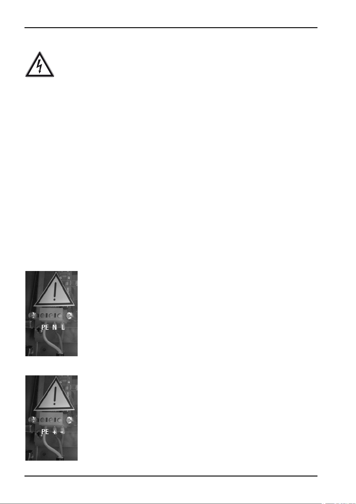
1.4.3 Connection of a protective earth conductor to PR 5230
1.4.3.1 Version 230 V AC
The instrument must be connected to protective earth via a protective earth conductor (PE) in the power
connector.
The power cable contains a protective earth conductor which must not be interrupted inside or outside the
instrument. The PE conductor is connected to the housing inside the instrument.
1.4.3.2 Version 24 V DC
The instrument must be connected to the protective earth conductor. The connection can be established via
the housing side wall.
1.4.4 Power Connection PR 5230
The instrument does not have a power switch and is ready for operation immediately after connecting the
supply voltage.
1.4.4.1 Version 230 V AC
Safe interruption of both supply voltage conductors must be provided for, either by
disconnecting the power connector or using a separate switch.
The instrument is equipped with a wide range power supply and covers AC systems with
a frequency of 50 Hz/60 Hz and a voltage range of 100 V AC to 240 V AC +10 %/-15 %
automatically (without manual selection). The power supply is protected against short
circuits.
1.4.4.2 Version 24 V DC
This version is designed for 24 V direct current.
The supply is done with a 3-pin connector (PE/+/-). The instrument is protected against
wrong polarity.
The instrument is primary protected by internal fuses in the + and – conductor.
EN-10 Sartorius
Page 11
PR 5230 Instrument Manual
Caution!
Safety Information
1.4.5 Failure and Excessive Stress
If there is any reason to assume that safe operation of the instrument is no longer ensured, shut it down and
make sure it cannot be used. Safe operation is no longer ensured if any of the following is true:
- The instrument is physically damaged.
- The instrument does not function.
- The instrument has been subjected to stresses beyond the tolerance limits (e.g., during storage or
transport).
1.4.6 Important Note
Make sure that the construction of the instrument is not altered to the detriment of safety. In particular,
leakage paths, air gaps (of live parts) and insulating layers must not be reduced. Sartorius cannot be held
responsible for personal injury or property damage caused by an instrument repaired incorrectly by a user or
installer.
1.4.7 Maintenance and Repair
Maintenance work must be carried out only by a trained technician aware of the involved hazards, whereby
the relevant precautions must be taken in account.
1.4.7.1 Static Sensitive Components
This instrument contains electro-statically sensitive components. Therefore, potential equalization must be
provided when working at the instrument (antistatic protection).
1.4.7.2 Replacing of Fuses in PR 5230 with Option Y2/WE1
In PR 5230 with option Y2/WE1 the replacing of fuses are not allowed!
1.4.7.3 Replacing of Fuses in PR 5230 without Option Y2/WE1
Only the fuses specified in Chapter 16.3 are permissible!
Sartorius EN-11
Page 12

Transmitter in Field Housing PR 5230 Instrument Manual
For the internal RS-232 or RS-485:
2 Transmitter in Field Housing
The instrument is equipped with a 128 x 64 pixel display for weight values with max. 6 digits and additional
status indication.
2.1 Overview of the Instrument
- Accuracy 10,000 e (Class III) for the weighing electronics
- High-speed conversion with response times from 5 msec
- Weight indication with status by monochrome 128 x 64 pixel display
- 3 function keys in the housing, function configurable
- Wall-mounted stainless steel housing, with IP 66 protection
- LAN adaptor with 10/100 Mbit/sec for data transfer, calibration, parameterization
- RS-232 interface, built-in; for connecting e.g. a printer or a remote indicator
- RS-485 interface, built-in; for connecting e.g. PC
- Expansion possible by addition of following plug-in circuit boards (3 slots):
- Analog output board PR 5230/06
- Load cell junction board PR 5230/22
- Interfaces PR 1721/4x
- 3 opto-decoupled outputs (optional)
- 3 configurable relay outputs with change-over contact
- 3 configurable optocoupler inputs, potential-free internal supply possible (optional)
- Galvanically isolated interfaces (except RS-232)
- Wide range power supply for 100 to 240 V AC, protection class I (protective earth)
- Version PR 5230 for 24 V direct current
- Version PR 5230 with intrinsically safe load cell supply (optional)
- Plug-in connections inside the instrument for load cells, inputs/outputs, LAN adaptor, serial interfaces
- Calibration using PC tool (Browser/VNC)
- Calibration using weights, by entering mV/V values, or directly, using load cell data ("smart calibration")
- Software configuration of the interface cards, e.g. for remote display or printer
- Analog test for the weighing electronics
Communication Protocols
Fieldbus Slave (accessories):
- Remote display protocol - PR 1721/41 ProfiBus-DP
- Printer - PR 1721/42 InterBus-S
- J-Bus/ModBus (Slave) - PR 1721/44 DeviceNet
- SMA protocol - PR 1721/45 CC-Link
- xBPI protocol - PR 1721/46 ProfiNet I/O
- Asycom protocol - PR 1721/47 EtherNet-IP
For the internal LAN:
- ModBus-TCP
- Ethernet-TCP/IP
- OPC
EN-12 Sartorius
Page 13
PR 5230 Instrument Manual
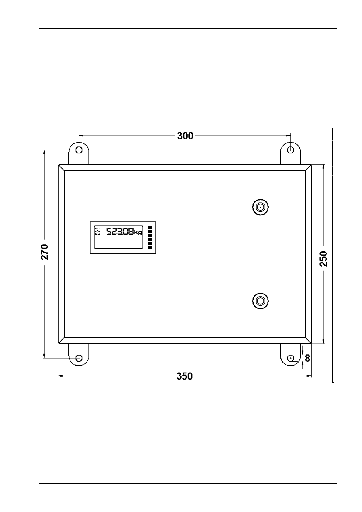
Height = approx. 120 mm
Transmitter in Field Housing
2.2 Housing
The transmitter is installed in a stainless steel field housing with protection type IP66. It is intended for wall
mounting. The door is left-hinged and opens towards the front. The environmental conditions specified for the
instrument must be observed (see Chapter 16.4.1). The housing is mounted using 4 screws. When the housing is
closed, no controls are visible from outside.
The 128 x 64 pixel display and 6 additional status indicator LEDs are visible through a glass pane in the housing
door.
Housing Dimensions
Sartorius EN-13
Page 14
Transmitter in Field Housing PR 5230 Instrument Manual
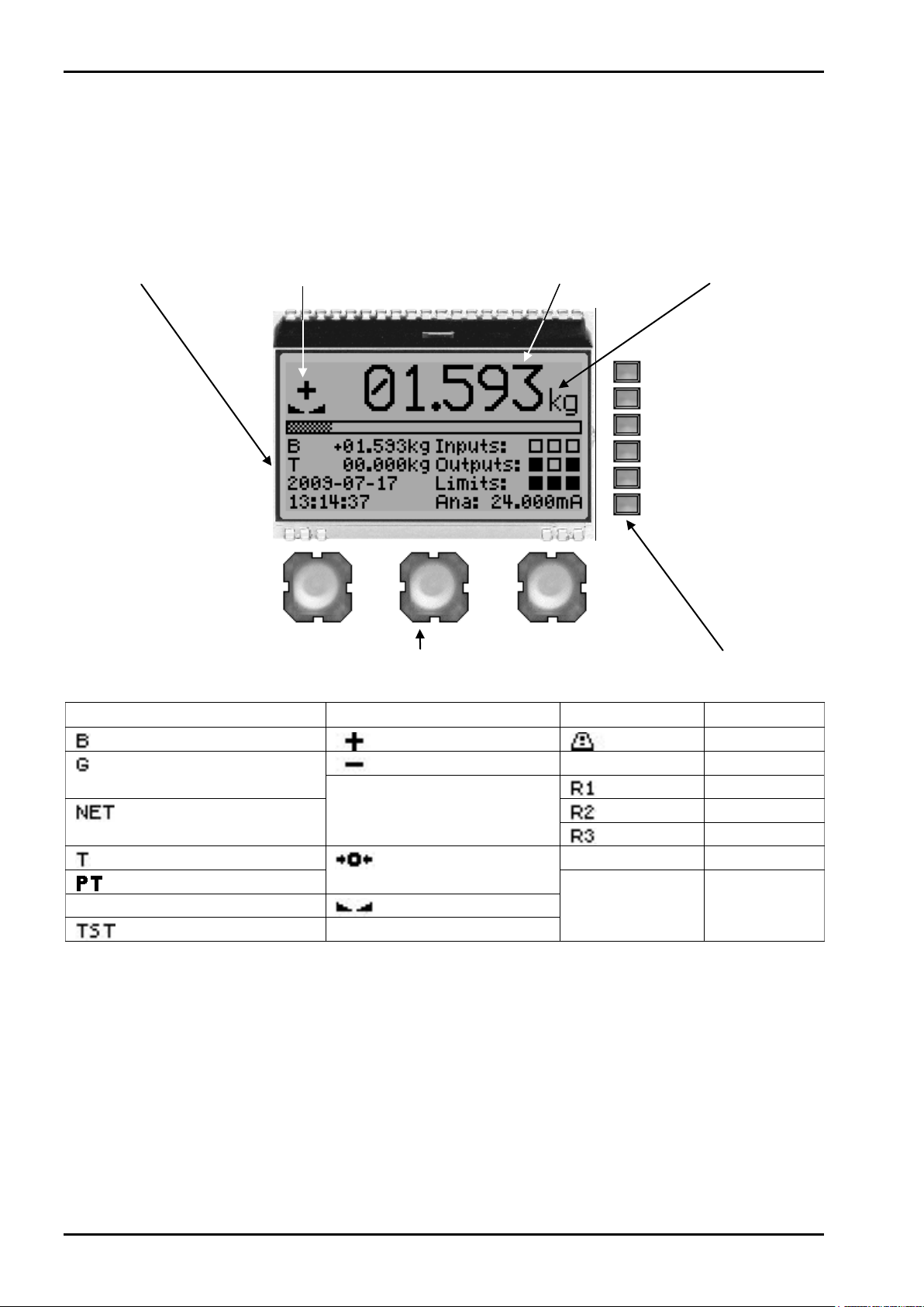
Status indication
Value type/polarity sign/Standstill
Weight value
Symbols/Mass unit
Keys
Status LEDs
Note:
2.3 Display and Controls
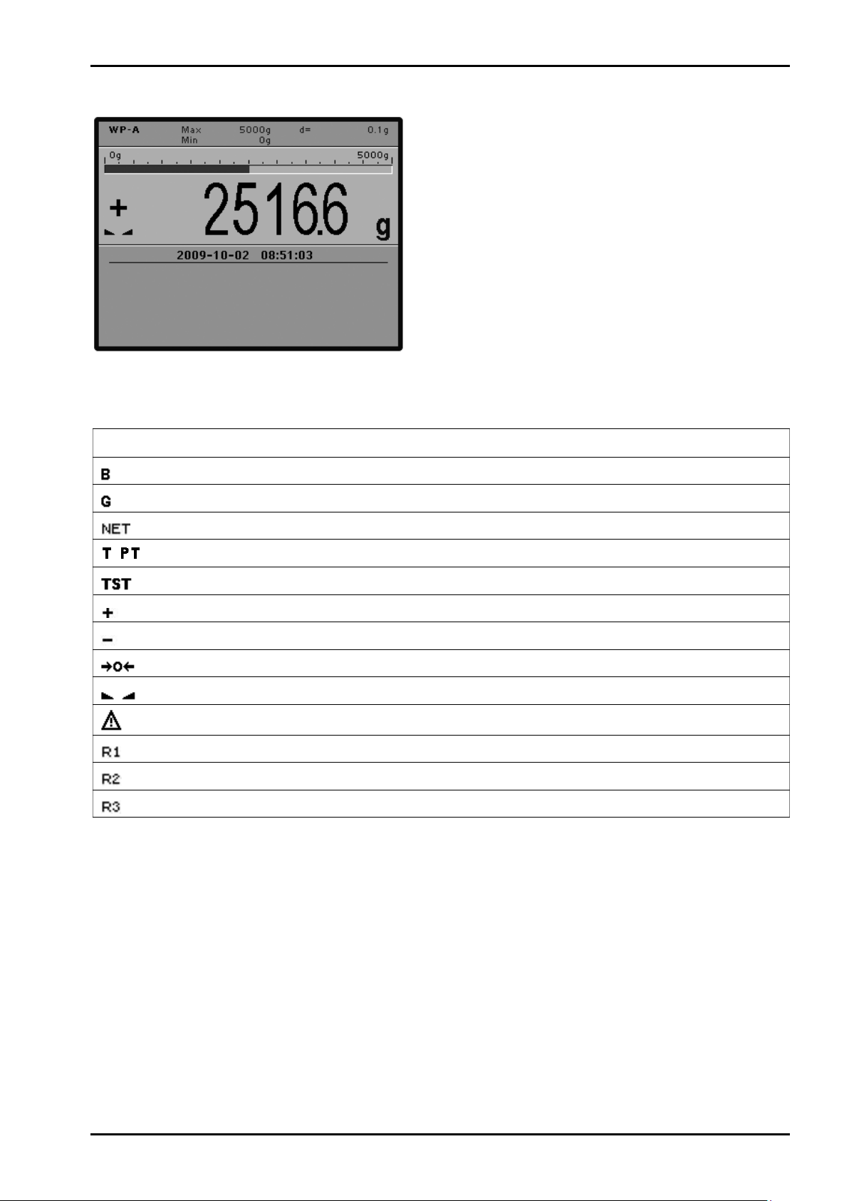
2.3.1 Display
The display permits indication of 6-digit weight values (digit height 18 mm) with decimal point.
Possible units of mass are mg, g, kg, t, lb or oz.
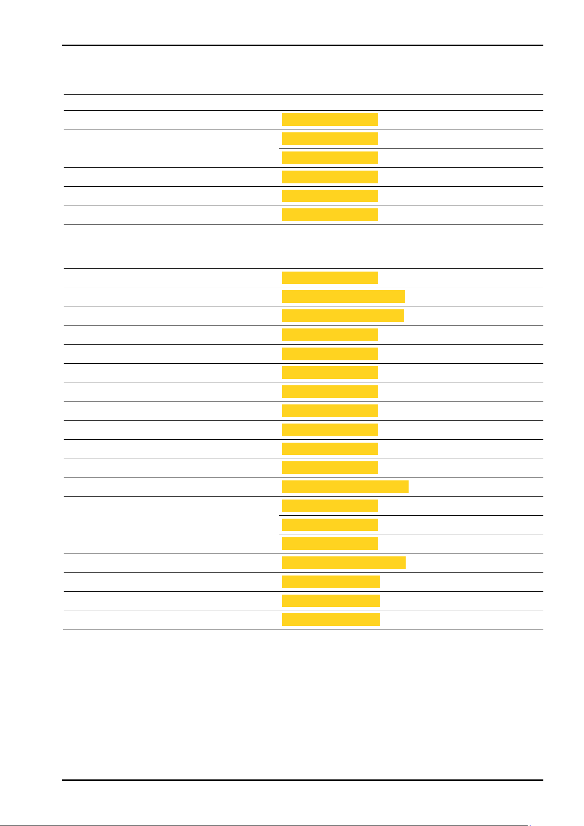
Value type Polarity sign/Standstill Symbols Mass unit
Gross weight (Brutto)
Gross weight
at NTEP or NSC mode The weight value is
Net weight
(Net = Gross – Tare)
Tare weight
Fixtare
Not tared
Test value
In W&M mode an invalid weight is shown without mass unit.
Positive value
Negative value g
between ¼ d and ½ d.
The weight value is
within ±¼ d of zero.
Standstill
oz
Warning mg
Range 1 kg
Range 2 t
Range 3 lb
EN-14 Sartorius
Page 15
PR 5230 Instrument Manual
Transmitter in Field Housing
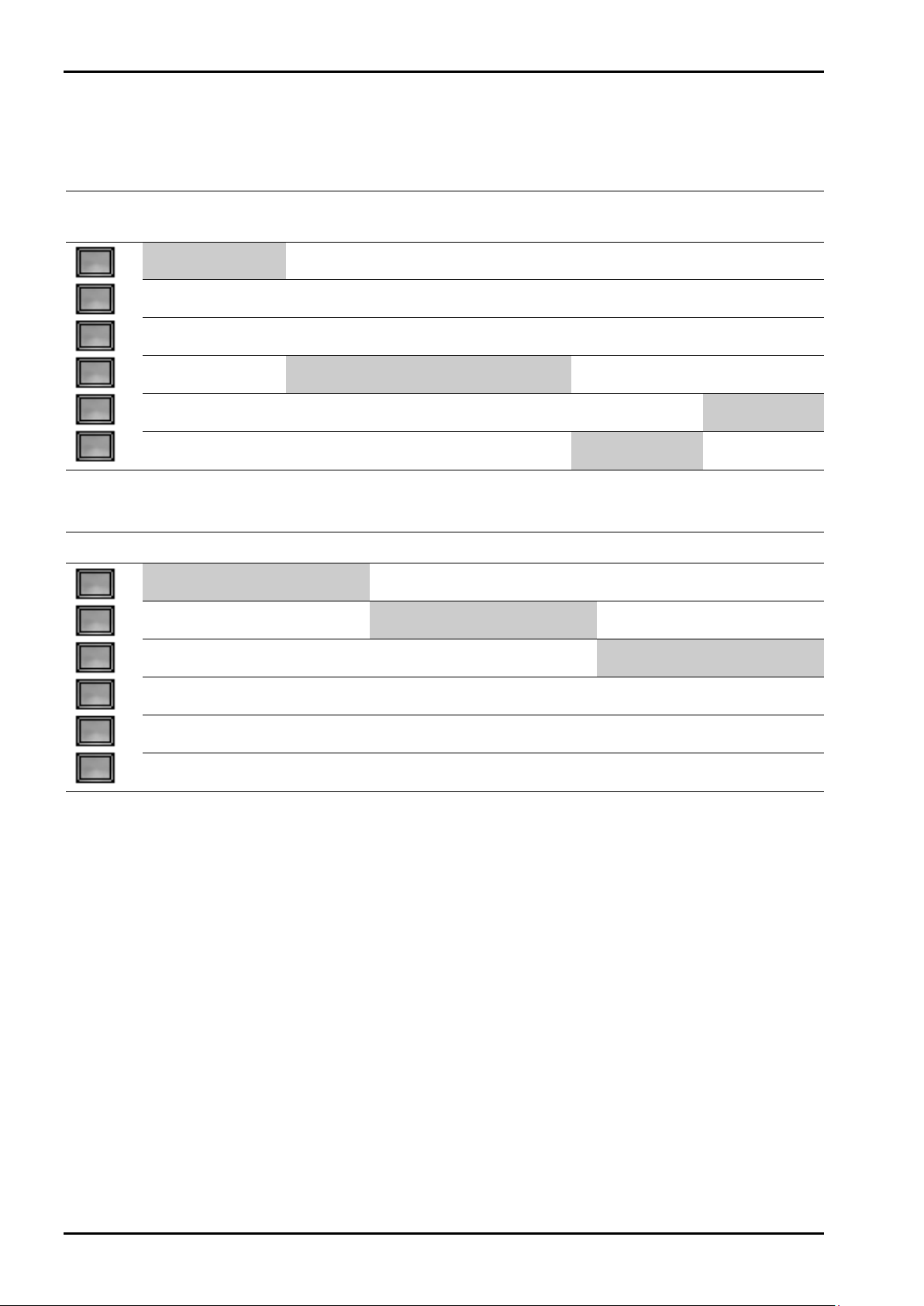
2.3.1.1 Status Indication
For status indication, max. 5 lines can be configured by selecting from a menu (see Chapter 5.6.7).
Selection Width Height Example Description
Empty ½ Display 1 Line
Gross/Net/Tare ½ Display 1 Line
Gross ½ Display 1 Line
Net ½ Display 1 Line
Tare ½ Display 1 Line
Bargraph 1 Display 1 Line
Fieldbus LEDs ½ Display 1 Line
Fieldbus Inputs 1 Display 1 Line
Fieldbus Outputs 1 Display 1 Line
Digital inputs ½ Display 1 Line
Digital outputs ½ Display 1 Line
Digital I/O ½ Display 1 Line
Analog output ½ Display 1 Line
B +123.45kg
B E:Sense
B +123.45kg
NET +123.45kg
T +123.45kg
––– red ––– grn
FB-Inp: 01.23.45.67.89.AB.CD.EF
FB-Out: 01.23.45.67.89.AB.CD.EF
Inputs:
Outputs:
I: O:
Ana: 12.345mA
Empty line
Gross/Net/Tare
Error, see Chapter 15.1
Gross
Net
Tare
Shows the weight in
proportion to nominal
capacity.
See Chapter 4.4.
Fieldbus Inputs
Fieldbus Outputs
Digital inputs: 1, 2, 3
Digital outputs: 1, 2, 3
Digital
Analog output
in-/outputs
: 1, 2, 3
Limits ½ Display 1 Line
Date ½ Display 1 Line
Time ½ Display 1 Line
Hostname ½ Display 1 Line
Hostname (long) 1 Display 1 Line
IP-Address ½ Display 1 Line
IP-Address (long) 1 Display 1 Line
Gross (2 lines high) 1 Display 2 Lines
Net (2 lines high) 1 Display 2 Lines
Tare (2 lines high) 1 Display 2 Lines
Limits:
2009-12-31
10:37:34
HOPPER1
Small Material Hopper
192.168.1.1
---.---.---.---
??.??.??.??
172.200.280.255
B +123.45 kg
NET +123.45 kg
T +123.45 kg
Limits: 1, 2, 3
Date
Time
Device name in the network
Device name (long)
Network address
No network
Search DHCP server
Network address (long)
Gross (2 lines high)
Net (2 lines high)
Tare (2 lines high)
Sartorius EN-15
Page 16
Transmitter in Field Housing PR 5230 Instrument Manual
Note:
2.3.2 Status LEDs
The instrument has 6 green LEDs for display of the operating or error status.
2.3.2.1 Hardware, Bus Connection (Fieldbus plug-in cards), Network, Power supply
Hardware error
E:HardE
flashing 1 Hz
Bus connection
provided
lit flashing 1 Hz
flashing acc.
lit
2.3.2.2 Weight Status Indicator
Standstill Center zero
lit
lit
Bus connection not
provided
Power on Network active
Below zero or above MAX
lit
The weight error status sees in Chapter 15.2.
EN-16 Sartorius
Page 17

PR 5230 Instrument Manual
1
2
3
Transmitter in Field Housing
2.3.3 Buttons
Danger! High Voltage!
Working on the opened instrument while it is switched on may have life-threatening
consequences.
Product operation must be performed by trained and qualified personnel who are aware
of and able to deal with the related hazards and take suitable measures for
self-protection.
The 3 buttons are accessible only when the housing door is open. The following functions can be performed:
- zero setting (1)
- taring (2)
- test measurement (3)
- display of software version and board number by simultaneous actuation of push-buttons (1) and (3)
- Updating a Software with ‚FlashIt!32’ (see Chapter 12.2) by pressing the keys (1) and (3) simultaneously
and pressing key (2) three times.
Adjustment or parameter entry is
- not possible using the push-buttons.
- only possible using a Notebook/PC via Internet browser (see Chapter 5.3.5) and VNC (see Chapter 5.3.4).
Sartorius EN-17
Page 18
Transmitter in Field Housing PR 5230 Instrument Manual
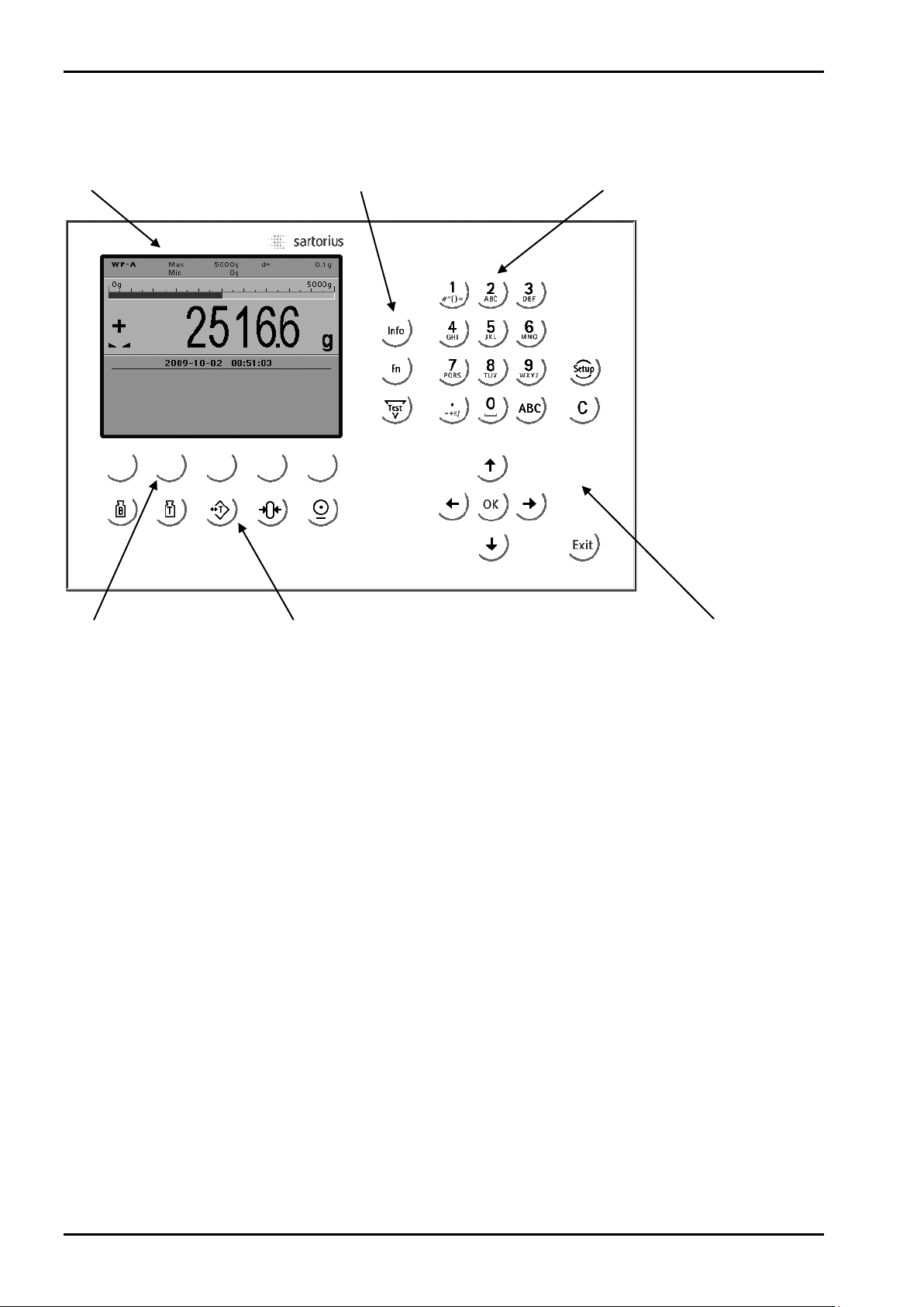
Display
Function keys
Alphanumeric keys
Softkeys
Indicator keys
Navigation/menu keys
2.3.4 Operating via VNC
2.3.4.1 Operator Interface
EN-18 Sartorius
Page 19
PR 5230 Instrument Manual
Available mass units are mg, g, kg, t, lb or oz.
The display shows weight values of up to 7 digits with decimal point and plus or minus sign.
lb and oz units are not permitted for use in legal
metrology in the EU and EEC.
The weight readout shows the current weight on a
bar graph that indicates proportion of the
maximum capacity (Max), with 0 on the left and
100 % on the right.
Transmitter in Field Housing
2.3.4.2 Status Symbols
The following status symbols can be shown:
Symbol Description
Gross weight (Brutto)
Gross weight in NTEP or NSC mode
Net weight (Net = gross – Tare)
, Tare weight, fixtare
The display shows the test value without mass unit
Positive value
Negative value
The weight value is within ±¼ d of zero
The weight value is stable.
Value not permissible in legal metrology (e.g., 10-fold resolution).
Range 1
Range 2
Range 3
Sartorius EN-19
Page 20
Transmitter in Field Housing PR 5230 Instrument Manual
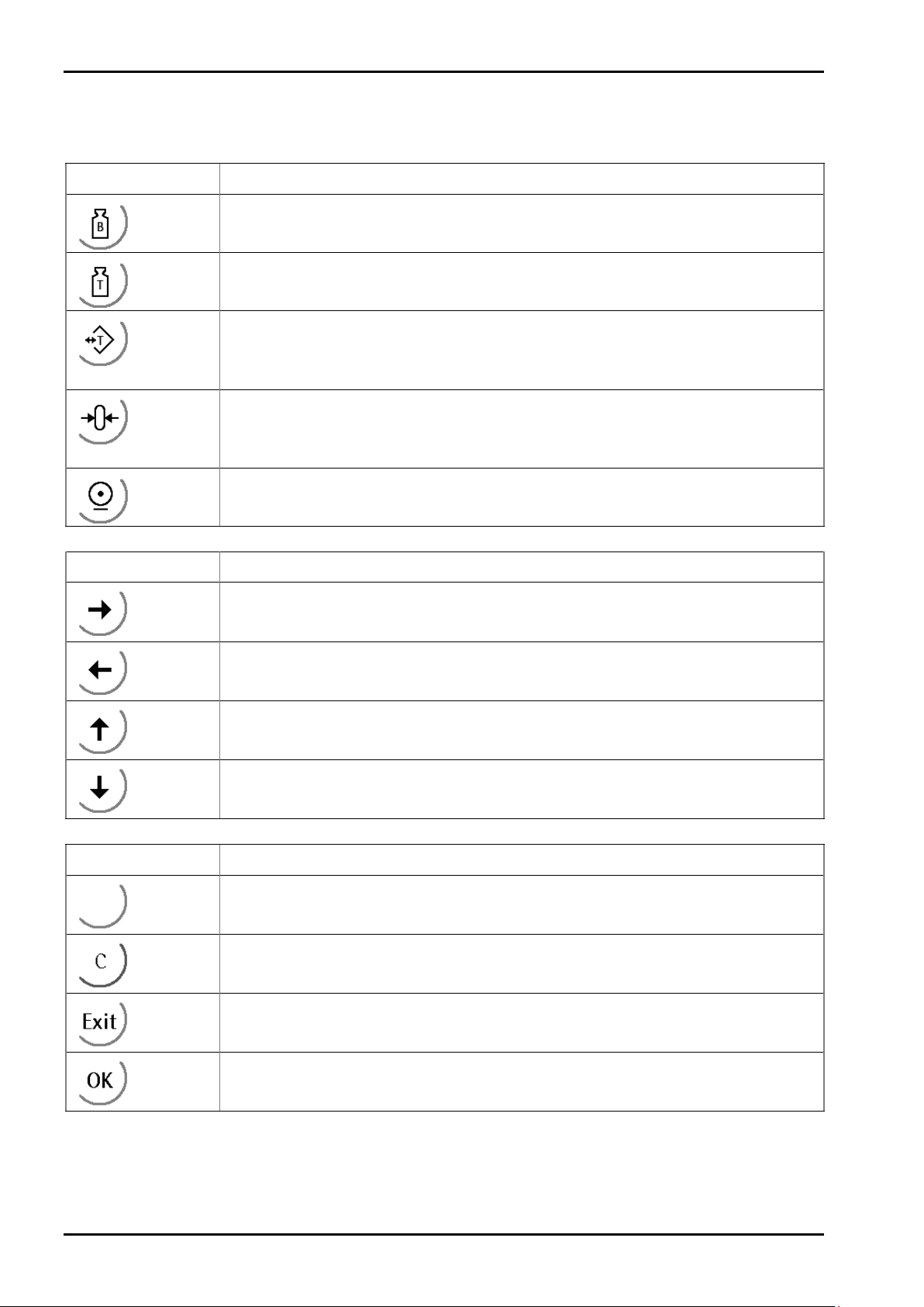
2.3.4.3 Keys
The following tables show the basic meanings of symbols on the operator interface.
Indicator key Description
Display gross weight
Display tare weight
Taring; the current gross weight is stored in the tare memory, provided that:
- weight value is stable.
- instrument is not in error status (function dependent on configuration).
Sets gross weight to zero, provided that (function dependent on configuration):
- weight value is stable.
- weight is within zero setting range
Start printing.
Navigation key Description
Cursor moves to the right.
Menu key Description
Selection
Cursor moves to the left.
Selection
Scroll up in the menu.
Scroll down in the menu.
Softkey: select function
Backspace/delete
Exit from current menu; continue operation on next higher level.
Enter/confirm
EN-20 Sartorius
Page 21
PR 5230 Instrument Manual
Setup
Config
Calib
Param
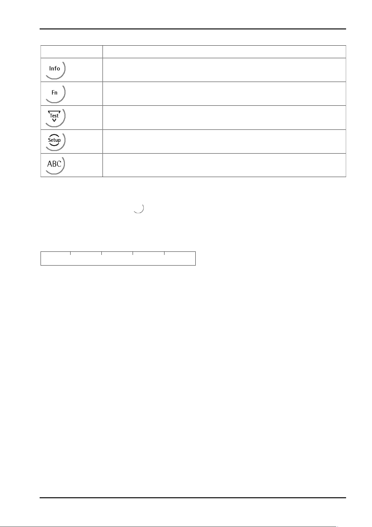
Function key Description
Information on version number, fitted hardware,10-fold resolution
Without function
Test
Open the setup menu
Toggle to alphabetic input mode.
During configuration, you can switch between the mass units by pressing this key.
2.3.4.4 Operation Using Softkeys
Transmitter in Field Housing
The functions of the five softkeys below the graphic display are indicated in the bottommost text line of
the display. Softkey functions shown in gray are not available on the active menu level, or not with the active
access privileges.
When operating steps involving softkeys are described in this manual, the softkey labels are shown in square
brackets, rather than in graphics of the softkeys.
Sartorius EN-21
Page 22
Transmitter in Field Housing PR 5230 Instrument Manual
Info
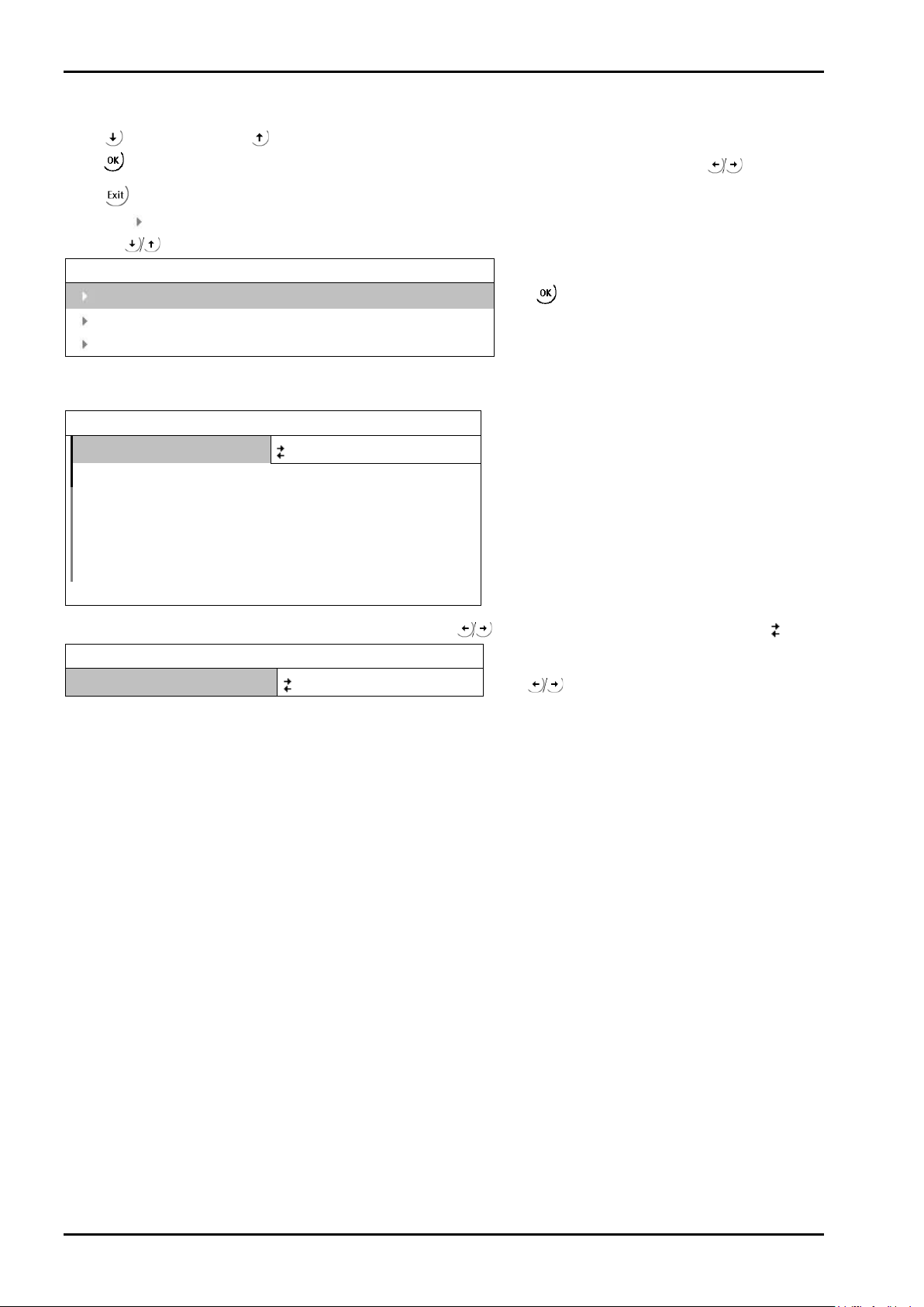
2.3.4.5 Selection Using the Navigation Keys (VNC)
Press to scroll down, or to scroll up in a menu.
Press
Press
An arrow
pressing
If the list of menu items is long, a vertical bar graph on the left (black and gray) shows which part of the list is
displayed.
to select a menu item. To select the desired setting for the selected menu item, press .
to exit the menu and continue the operation on the next higher level.
in front of a menu item indicates that there are menu sublevels. The menu item selected by
is shown inversely.
Show version
Show status
Show HW-slots
Weighingpoint/WP A/Calibration
Measuretime
Digital filter off
External supply above 8V
Test mode absolute
W & M
Standstill time 0.50 s
160 ms
none
Press
to select an item.
Availability of additional settings options selectable with is indicated by preceding double arrows .
Weighingpoint/WP A/Calibration
Measuretime
640 ms
Press
to select the measuring time.
EN-22 Sartorius
Page 23
PR 5230 Instrument Manual
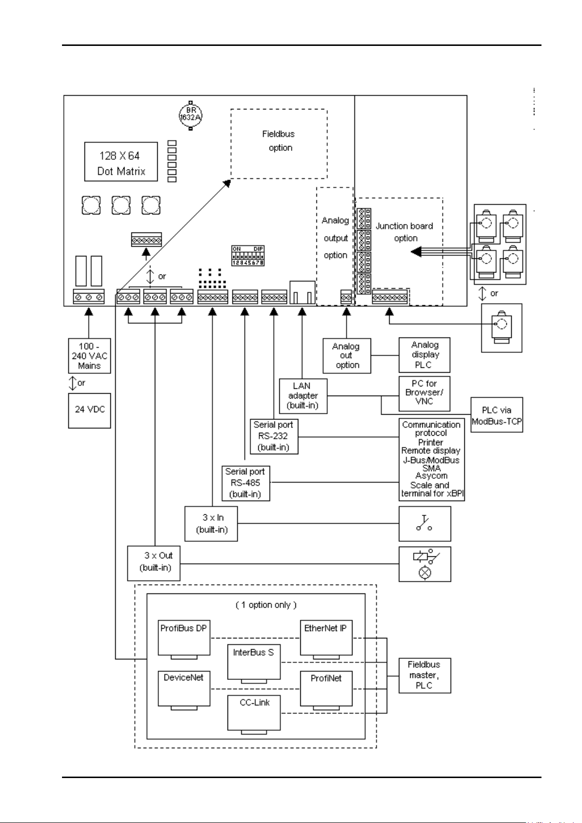
2.4 Overview of Connections
Transmitter in Field Housing
Sartorius EN-23
Page 24

Transmitter in Field Housing PR 5230 Instrument Manual
2.4.1 Plug-in Cards/Junction Board
On the main board, the PR 5230 can be fitted with 1 fieldbus card and 1 analog output board.
The load cell junction board is connected to the weighing electronics board by a flat cables plug.
Product Function Position
PR 5230/06
Analog output
PR 5230/22
Load cell junction board
PR 1721/41
ProfiBus-DP
PR 1721/42
InterBus-S
PR 1721/44
DeviceNet
PR 1721/45
CC-Link
PR 1721/46
ProfiNet I/O
PR 1721/47
EtherNet-IP
For product details, see Chapter 4.2 and 4.3.
Analog output 16 bits, 0/4 - 20 mA Analog output
Junction board for 2…4 load cells Junction board
ProfiBus-DP Slave acc. IEC 61158 with
max. 12 Mbit/s
InterBus-S Slave with max. 500 kbit/s Fieldbus
DeviceNet Slave with max. 500 kbit/s Fieldbus
CC-Link with 156 kbit/s…10 Mbit/s Fieldbus
ProfiNet I/O with 10 / 100 Mbit/s Fieldbus
EtherNet-IP with 10 / 100 Mbit/s Fieldbus
Fieldbus
EN-24 Sartorius
Page 25
PR 5230 Instrument Manual
Fehler!
Verweisquell
e konnte
nicht
gefunden
werden.
Options
3 Options
Designation Code no. Description Chapter
Analog/digital
converter
W1 Weighing electronics board
EX WE1 Weighing electronics board with
power supply Standard L0 Version 230 V 1.4.4.1
L8 Version 24 V 1.4.4.2
IP protection I66 IP66
Digital input DE1 Digital input, passive (external supply) 4.2.6.1
DE2 Digital input aktive (internal 12 V supply) 4.2.6.2
Digital output DA1 Digital output relay 4.2.8
DA2 Digital output Optocoupler 4.2.7
EX Zone Standard none
Y2 Approval ATEX/EU, Zone 2/22 3.1
Interface Slot 1 Standard none
C11 Analog output 16 bits, 0/4 - 20 mA 4.4.2
Interface Slot 2 Standard none
C21 ProfiBus-DP 4.4.4
C22 InterBus-S 4.4.5
C24 DeviceNet 4.4.6
C25 CC-Link 4.4.7
C26 ProfiNet I/O 4.4.8
C27 EtherNet-IP 4.4.9
Interface Slot 3 Standard none
C31 Load cell junction board 4.4.3
Connecting cable Standard none
for network M39* Ethernet socket, RJ-45 plug, IP67 4.4.10
M40* Ethernet cable, 7m long,
* For the Builtin Ethernet interface only!
Standard none
intrinsically safe load cell supply for
operation of load cells/platforms
in Zones 1 and 21
4.4.11
metric cable gland, RJ-45 plug,
industry version
3.2
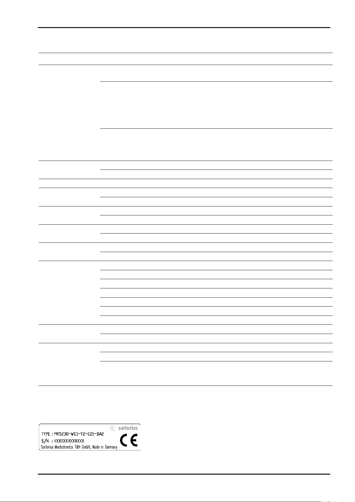
Instrument Option
The marking (e.g. PR 5230-WE1- Y2-C21-DA2) of the instrument option is located on a label inside the door of
the instrument.
Sartorius EN-25
Page 26
Options PR 5230 Instrument Manual
3.1 Option Y2
3.1.1 Safety Instructions
Caution!
It is essential to observe the safety instruction in Chapter 18.4!
3.1.2 Description
PR 5230 with option Y2 is only suitable for using within Ex areas Zone 2 and 22 (non conductive dust)
according European directive 94/9/EG and related harmonized European standards (see also Chapter 18.4).
The Ex design for Zone 2/22 see Chapter 18.4.
3.1.3 Marking
II 3G Ex nA nC IIC T4
II 3D Ex tD A22 IP6X T80°C
SAG 09ATEX004X
See also Chapter 18.4.
3.1.4 Outputs
With option Y2 are following outputs possible:
- Opto-decoupled outputs (option DA2): Technical Data see Chapter 16.5.8.2.
- Relays (option DA1): Only external circuits with voltages up to 60 V AC or 75 V DC are allowed to be
connected to the relays, see Safety Instruction in Chapter 18.4.
3.1.5 In Connection with Option W1
Connected load cells or weighing platforms must be certified for use in Ex areas Zone 2 or Zone 22 and for
load cell supply voltages of more than 13.2 V DC.
When use
- in Zone 2 observe gas group and temperature class.
- in Zone 22 observe the allowed surface temperature.
3.1.6 In Connection with Option WE1
The combination Y2 and WE1 is also possible; see Ex design for Zone 2/22 and Zone 1/21 in Chapter 18.4.
EN-26 Sartorius
Page 27
PR 5230 Instrument Manual
Danger!
Options
3.1.7 Installation
The installation must be performed by qualified personnel in compliance with the applicable laws, regulations,
ordinances and standards. In particular, the standards EN 60079-14 (gas) and EN 61241-14 (dust) must be
taken into account.
All cables to and from PR 5230 have to be installed firmly.
It is only allowed to connect instruments (not sparking during operation) to power circuits in Zone 2 which are
suitable for Zone 2 and the local conditions at the operating location.
Not used cable glands must be closed with ATEX approved screwings in order to secure IP65 protection.
Working at the switched on unit may be dangerous to life!
• Disconnect the instrument from the supply voltage.
• When removing covers or parts by means of tools, live parts or terminals may be
exposed.
• Capacitors in the unit may still be charged also after disconnecting the unit from all
voltage sources.
3.1.8 Repairs/Cleaning/Maintenance
Warning!
In the Ex atmosphere it’s not permissible to mount/loose plug connectors or to change
fuses!
Any modifications to the instrument (except by persons authorized by Sartorius) cause loss of conformity for
use in Zone 2 and 22 hazardous areas and invalidate all guarantee claims. Similary, the instrument may only be
opened by qualified and authorized persons.
Repairs are subject to inspection and must be carried out at Sartorius. In case of defect or malfunction, please
contact your local Sartorius dealer or service center for repair. When returning the instrument for repair,
please include a precise and complete description of the problem.
Instruments used in Zone 22 remove dust regulary. Dust layers >5 mm are not permitted.
Maintenance work may be carried out only by a trained technician with expert knowledge of the hazards
involved and the required precautions.
3.1.9 Environmental Conditions
Use the transmitter only within the temperature range of -10 °C…+40 °C. Avoid the inadmissible exposure of
heat, cold, direct sunlight, UV radiation or vibration. Install the instrument in that way, that air circulation is
possible and heat sources are sufficient far away.
Sartorius EN-27
Page 28
Options PR 5230 Instrument Manual
3.2 Option WE1
3.2.1 Safety Instructions
Caution!
It is essential to observe the safety instruction in Chapter 18.4!
3.2.2 Description
The option WE1 is used for an intrinsically safe interface of load cells or weighing platforms situated in a
hazardous (Ex) area Zone 1 and 21 with PR 5230 installed in a safe area according European directive 94/9/EG
and related harmonized European standards (see also Chapter 18.4).
The unit is designed for weighing applications requiring intrinsically safe interfacing. This is achieved by use of
double provided current and voltage limiters in the supply circuit and voltage limiters in the analogue
elektonic (weighing electronics board) of the PR 5230 with option WE1.
The PR 5230 with option WE1 provides the intrinsically safe interfacing of:
- 1 voltage output for the supply of load cells or weighing platforms situated in Zone 1 or 21,
- 1 measuring voltage input from Zone 1 or 21 and
- 1 sense voltage input from Zone 1 or 21.
3.2.3 Marking
II (2) G [Ex ib] IIC
II (2) D [Ex ib D]
KEMA 10 ATEX 0065 X
See also Chapter 18.4.
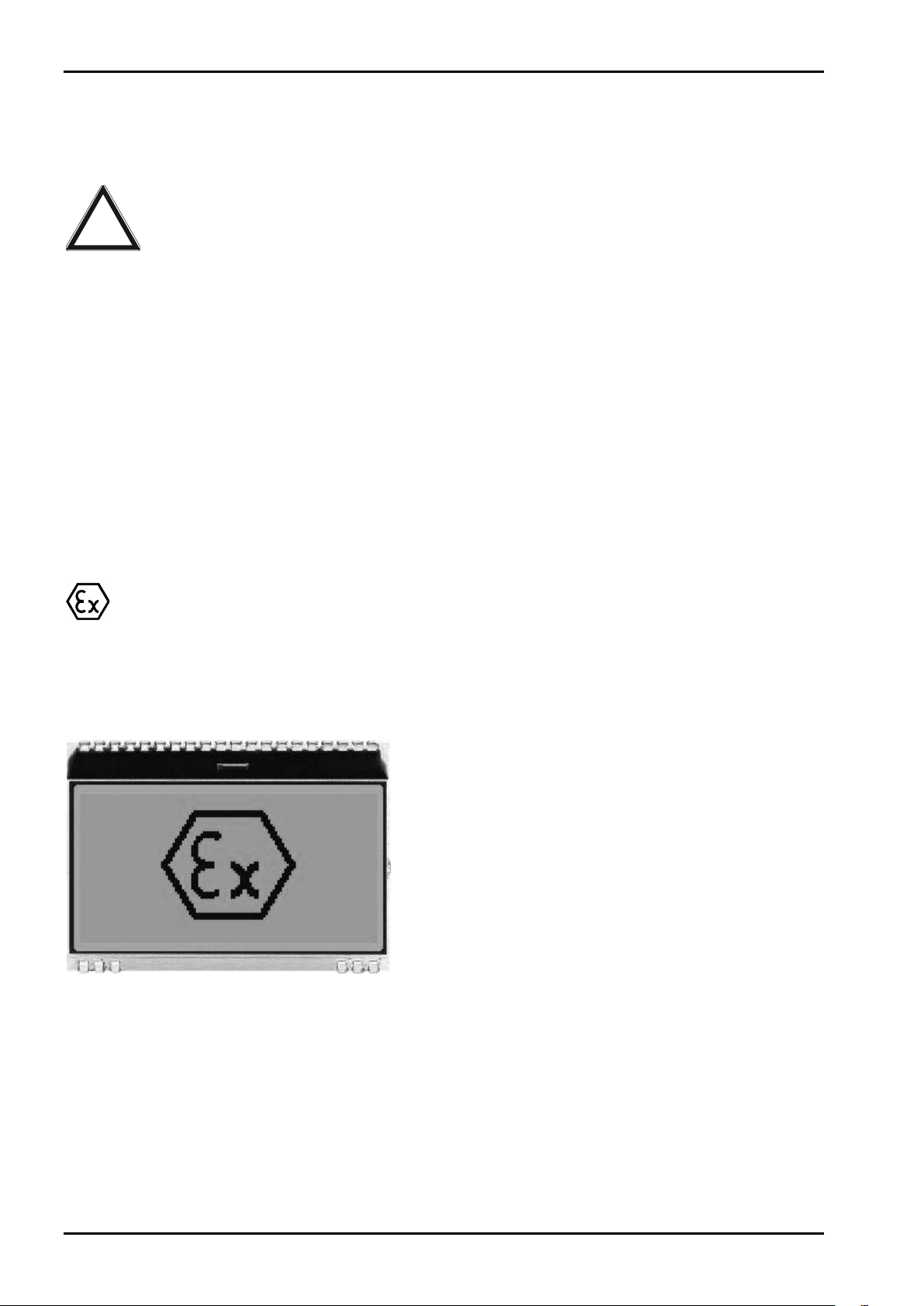
3.2.4 Display
After switching on the instrument the following information is short-time displayed:
3.2.5 In Connection with Option Y2
The combination WE1 and Y2 is also possible; see Ex design for Zone 2/22 and Zone 1/21 in Chapter 18.4.
EN-28 Sartorius
Page 29
PR 5230 Instrument Manual
Options
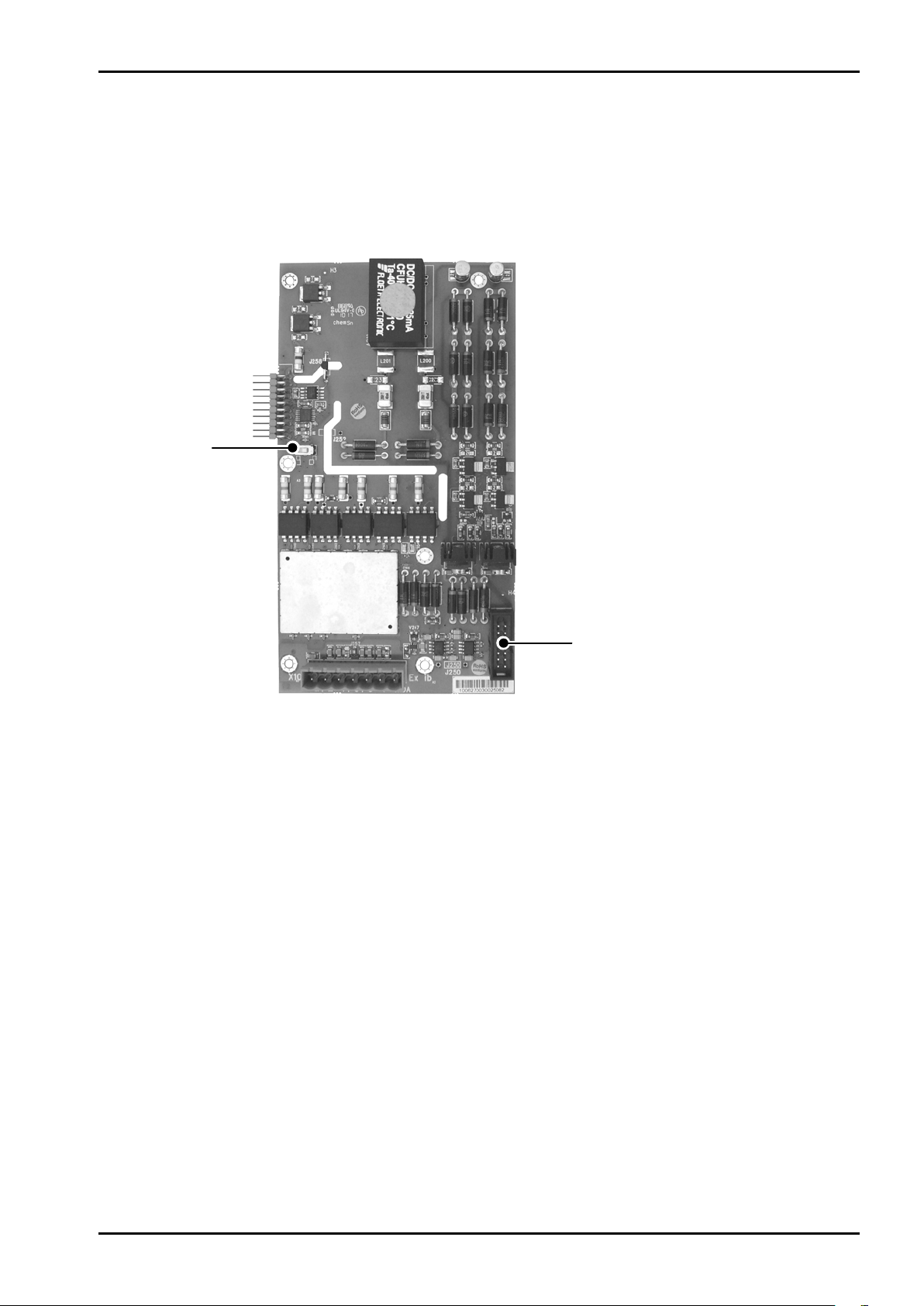
3.2.6 Weighing Electronics Board for Zone 1 and 21
Two weighing electronics board versions are available:
- Standard (W1), see Chapter 4.2.3
- With intrinsically safe load cell supply for operation of load cells/platforms in Zones 1 and 21 (WE1)
The load cell junction board (see Chapter 4.4.3) is connected to the weighing electronics board via a ribbon
cable (also permitted for WE1) for direct connection of up to four load cells.
CAL switch
Connector load cell junction board
Sartorius EN-29
Page 30
Options PR 5230 Instrument Manual
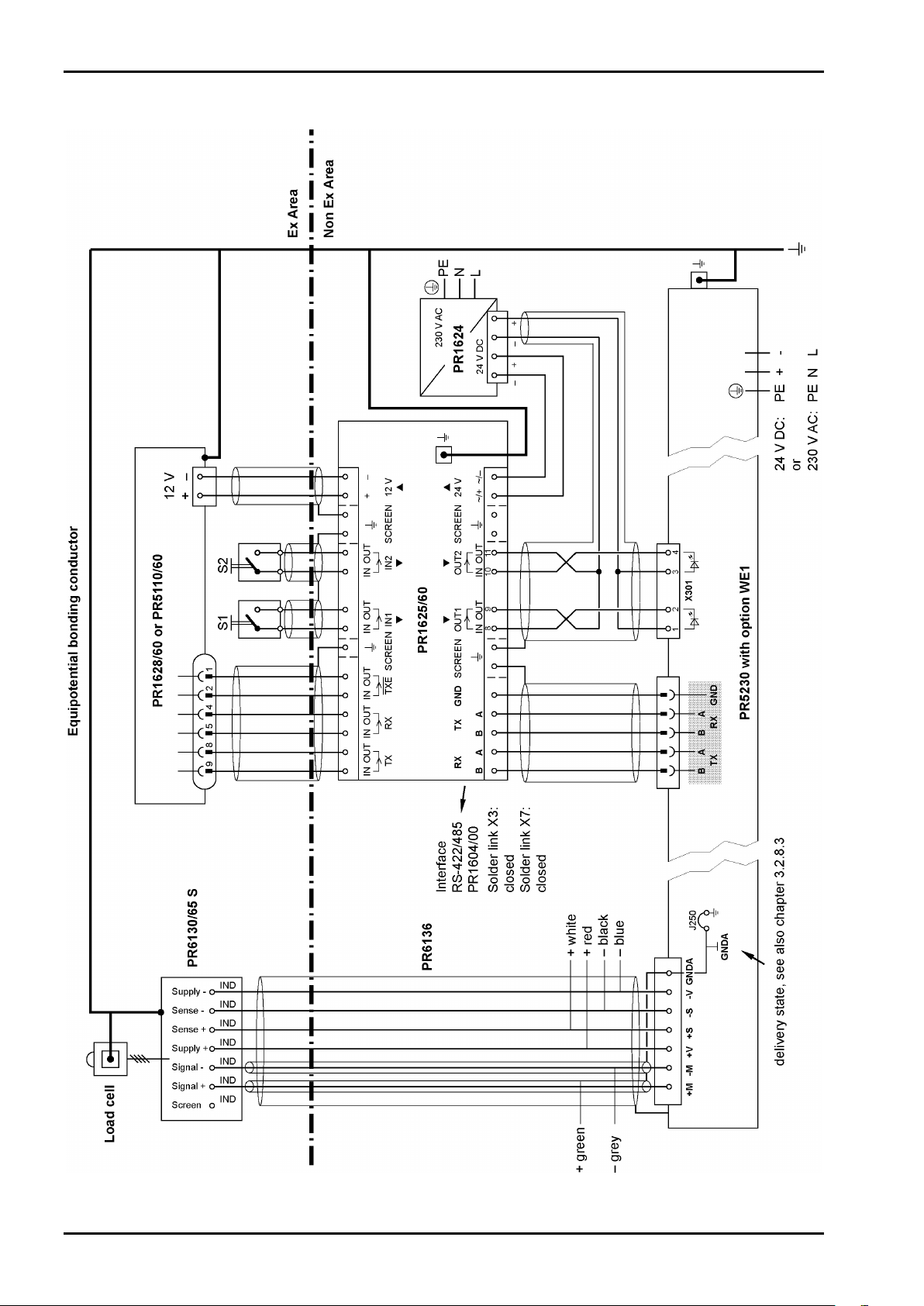
3.2.7 Connection within the Ex Area
EN-30 Sartorius
Page 31

PR 5230 Instrument Manual
Danger!
Options
3.2.8 Installation
3.2.8.1 General
The installation must be performed by qualified personnel in compliance with the applicable laws, regulations,
ordinances and standards. In particular, the standards EN 60079-14 (gas) and EN 61241-14 (dust) must be
taken into account.
All cables to and from PR 5230 have to be installed firmly.
Not used cable glands must be closed with ATEX approved screwings in order to secure IP65 protection.
Working at the switched on unit may be dangerous to life!
• Disconnect the instrument from the supply voltage.
• When removing covers or parts by means of tools, live parts or terminals may be
exposed.
• Capacitors in the unit may still be charged also after disconnecting the unit from all
voltage sources.
Sartorius EN-31
Page 32

Options PR 5230 Instrument Manual
3.2.8.2 Reduction in the Load Cell Supply Voltage
The solder links ‚J203’ and ‚J204’ are situated on the weighing electronics board.
The load cell supply voltage can be changed by closing the solder links.
Load Cell Supply Voltage
open 12 V DC nominal, if RLC ≥150 ¥
closed 7,2 V DC nominal, if 80 ¥ ≤RLC <150 ¥
J203
J204
Solder links
open (delivery state)
closed
open (delivery state)
closed
J203
J204
EN-32 Sartorius
Page 33

PR 5230 Instrument Manual
Options
3.2.8.3 Potential-free Load Cell Supply Voltage
The instrument with option WE1 will be delivered with an intrinsically safe circuit which is galvanically
connected with the equipotential bonding (PA).
Jumper J250
At distances >50 m a potential-free load cell supply voltage is required. This is done as follows:
• Cut the jumper J250 on the weighing electronics board.
• Turn the remaining wire leads upward and cut them just above the board. Make sure that both contacts
have a minimum distance of 2 mm and don’t touch other potentials.
If the jumper J250 is open, the intrinsically safe circuit is isolated from the housing (PA) at a minimum test
voltage of 500 V.
Sartorius EN-33
Page 34

Options PR 5230 Instrument Manual
PR5230-WE1-…
Load Cells
Wägezellen
Junction Box
Verbindungskasten
Ex Area Zone 1/21
Ex-Bereich Zone 1/21
Non Ex Area
Kein Ex-Bereich
(1) (2) (1) (1) (2) (3)
(6) (6)
(A)
(4)
(4) (4)
(A) (A) (A) (A) (A) (A)
(E)
(5)
(B)
(1)
≥
≥
≥
3.2.8.4 Potential Equalization
Possible compensatory currents between several conducting plant sections will be avoid by installing a
potential equalization in the ex areas.
Pos. Component Cross-section
(1) Conductor for additional potential equalization
(2) Conductor for potential equalization
(3) Conductor for potential equalization
(4) Main conductor for potential equalization
(5) Earthing conductor
(6) Load cell by-pass
4.0 mm² Cu
6.0 mm² Cu
10.0 mm² Cu
≥10.0 mm² Cu
≥10.0 mm² Cu
≥10.0 mm² Cu
(A) Sub potential equalization terminal
(B) Main potential equalization terminal
(E) To earth electrode
EN-34 Sartorius
Page 35

PR 5230 Instrument Manual
3.2.8.5 Screenings
Danger!
Incorrect connection of the connecting cable screens may have consequences of severe
damage for personal and plant!
At distances >50 m the screen may only be connected at one end:
• Connect the connecting cable screen to PR 5230, see Chapter 4.2.4.
• Open the jumper J250 on the weighing electronics board, see Chapter 3.2.8.3.
• Load cells with cable screen connected to the housing and using the
junction box PR 6130/64 Sa:
• Connect the connecting cable screen, see Installation Manual.
• Open the link above the Sense terminal block on the board of the junction, see
Installation Manual.
• Load cells with cable screen connected to the housing and using the
junction box PR 6130/65 S:
• Don’t connect the connecting cable screen, see also Chapter 3.2.7.
Options
3.2.9 Repairs/Cleaning/Maintenance
Warning!
In PR 5230 with option WE1 it’s not permissible to mount/loose plug connectors or to
change fuses!
Repairs are subject to inspection and must be carried out at Sartorius. In case of defect or malfunction, please
contact your local Sartorius dealer or service center for repair. When returning the instrument for repair,
please include a precise and complete description of the problem.
Maintenance work may be carried out only by a trained technician with expert knowledge of the hazards
involved and the required precautions.
Sartorius EN-35
Page 36

Options PR 5230 Instrument Manual
3.2.10 Technical Data
Note:
Further technical data of PR 5230 see Chapter 15.
3.2.10.1 General Data
Accuracy <10000 e (Klasse III) according to OIML R76/EN 45501
Connection for the non Ex area via 4mm2 screw terminals
Connection for the Ex area via 4mm2 screw terminals
Intrinsically safe output Protection class Ex ib IIC
Potential equalization Via screw terminal PE, see Chapter 3.2.8.4
3.2.10.2 Power Connection 230 V AC
Supply voltage 100…230 V AC ±10 %
Power consumption 16 VA
Frequency 50…60 Hz ±2 Hz
3.2.10.3 Power Connection 24 V DC
Supply voltage 24 V DC ±10 %
Power consumption 12 W
3.2.10.4 Output Parameter (intrinsically safe) for the Connection of Load Cells/Junction Box/Weighing Platforms
The connection will be done via 7-pin plug (marked with ‚X100’ and ‚Exib’) on the weighing electronics board.
Uo 21.0 V between the lines
lo 143 mA
Po 1.55 W
Co 188 nF between the lines
Lo 0.12 mH
EN-36 Sartorius
Page 37

PR 5230 Instrument Manual
≤
sense
3.2.10.5 Load Cells
Options
Supply voltage
Tolerance range ±5.8…±6.2 V DC; ±3.4…±3.8 V DC
Max. current
Measuring voltage V
Sense voltage V
±3.6 V nominal (with ref. to ground)
meas
±6 V nominal (with ref. to ground)
±6 V DC (nominal)/≤96 mA Max. 4 load cells of 650 Ω each, connected in
parallel (= 162.5 ¥)
±3.6 V DC (nominal)/≤96 mA Max. 8 load cells of 650 Ω each, connected in
parallel (= 81.3 ¥)
or
4 load cells of 350 Ω each, connected in parallel
(= 87.5 ¥)
100 mA short circuit
Max. 36 mV (differential)
3.2.10.6 Connection Cable
Length of the connection cable between junction box and PR 5230
Type PR 6135, PR 6135A Max. 200 m – length of the load cell cable
Length of the connection cable between weighing platform and PR 5230
Type LiYCY Max. 200 m
3.2.10.7 Environmental Conditions
Use the transmitter only within the temperature range of -10 °C…+40 °C. Avoid the inadmissible exposure of
heat, cold, direct sunlight, UV radiation or vibration. Install the instrument in that way, that air circulation is
possible and heat sources are sufficient far away.
Sartorius EN-37
Page 38

Installing the Instrument and Plug-in Cards PR 5230 Instrument Manual
Display board
Main board
Weighing electronics board
4 Installing the Instrument and Plug-in Cards
Before starting work, please read Chapter 1 and follow all instructions!
Further procedures:
• Check the consignment: unpack the components specific to the application.
• Safety check: inspect all components for damage.
• Make sure the on-site installation is correct and complete including cables, e.g. power cable fuse
protection, load cells, junction box, data cable, console/cabinet, etc.
• If necessary, mount the plug-in cards (instrument must be disconnected from all voltage sources).
• Follow the instructions for installation of the unit relating to application, safety, ventilation, sealing and
environmental influences!
• Connect the cable from junction box or platform/load cell.
• If applicable: connect other data cables, power cable, etc.
• Connect the instrument power cable.
• Check the installation.
4.1 Mechanical Preparation
Have all required parts, technical documents and tools at hand for mounting. Secure the cable at the place of
installation; e.g., using cable ties. Remove the insulation from the cable ends, keep the strands short and fit
them with ferrules
4.2 Hardware Construction
The main electronics circuitry is accommodated on the following PCBs:
- Main board
- Display board
- Weighing electronics board
EN-38 Sartorius
Page 39

PR 5230 Instrument Manual
Display board
Lithium battery
Power supply
3 relay outputs
Digital inputs
2 serial interfaces
Installing the Instrument and Plug-in Cards
4.2.1 Main Board
The main board provides the sockets for the
- Analog output board (accessories)
- Fieldbus plug-in card (accessories)
The lithium battery is always activated and energizes the calendar/clock module
Fieldbus plug-in card
Analog output board
Network port
Sartorius EN-39
Page 40

Installing the Instrument and Plug-in Cards PR 5230 Instrument Manual
Note:
The weighing electronics board (W1) is also available as a spare, see Chapter Fehler!
Verweisquelle konnte nicht gefunden werden.
4.2.2 Display Board
The display board is connected to the main board by a flat cables plug, see also Chapter 3.2.6.
4.2.3 Weighing Electronics Board
The weighing electronics board is connected to the main board by a plug.
Two weighing electronics board versions are available:
- Standard (W1)
- With intrinsically safe load cell supply for operation of load cells/platforms in Zones 1 and 21 (WE1),
see Chapter 3.2.6
The load cell junction board (see Chapter 4.4.3) is connected to the weighing electronics board via a ribbon
cable for direct connection of up to four load cells.
CAL switch
Connector load cell junction board
EN-40 Sartorius
.
Page 41

PR 5230 Instrument Manual
Caution!
Installing the Instrument and Plug-in Cards
4.2.4 Cable Gland and Connection
The cables have to be fed into the instrument via glands to ensure the increase. Cable diameters of 9…13 mm
for the cable gland M20x1.5 (4x) and 5…9 mm for the cable gland M16x1.5 (10x) are suitable. The conductors
are connected to screw terminals inside the instrument. Max. conductor cross-section 2.5 mm
The connections are made via plug-in screw terminals. The conductors taken to the terminals shall be as short
as possible. The conductors of each cable must be tied together with a cable strap shortly before the terminal
block.
For protection during transport and installation, the cable glands are fitted with a
polyethylene cover.
For full IP protection, operation with the dust protection cover fitted is not
permissible!
If a cable gland is not used, it must be sealed with a supplied blind plug.
Cabling
In principle, the cables can be taken through all cable glands corresponding to the cable diameters. The
following figure shows a cabling proposal.
1 2 3 4 5
2
.
8 7 6
Legend
Pos. Description
1 Power supply: 230 V AC or 24 V DC
2 Digital outputs: Relays/Optocoupler
3 Serial interfaces
4 Ethernet socket (option/accessory)
5 1…4 load cells
6 1 load cell or junction box or fieldbus cards
7 Analog output or fieldbus cards
8 Digital input: internal/external
Sartorius EN-41
Page 42

Installing the Instrument and Plug-in Cards PR 5230 Instrument Manual
Caution!
1
2
3 4 5 6 7
Caution!
Caution!
Mounting the Cable
The connection of the cable screen of the fieldbus cards:
essential see according Chapter 4.4.4 …4.4.9!
The cable screen (4) must be connected in the metal sleeve (6) of the cable gland.
Don’t take the screen (4) into the unit!
Before, during and after installation, make sure that the sealing ring is seated
correctly.
• Remove the (screw) cap (1).
• Slide cap (1) and plastic cone (3) over the cable (2).
• Take the cable (5) through the metal sleeve (6).
• Fold the cable screen (4) over the lower part of the plastic cone (3) (approx. 10 mm).
• Connect the cable conductors.
• Tighten the (screw) cap (1).
• Tighten metal sleeve (6) inclusive o-ring (7) by lock nut (inside the housing).
Regularly check the cable gland for tightness and re-tighten it, if necessary.
EN-42 Sartorius
Page 43

PR 5230 Instrument Manual
Transfer rate
Connection method
Cable
Cable impedance
Electrical isolation
Cable length
Connection
Remote operation of the PR 5230 from the Notebook/PC is
Number of inputs
Input signal
Input current
Electrical isolation
Connection
Cable
Installing the Instrument and Plug-in Cards
4.2.5 Network Port
The network port is built in as standard equipment. The port contains powerful TCP/IP connection circuitry
with transfer rates of 10 or 100 Mbit/sec. Function checking is possible via the LED to the right of the
display (act) or via the LED in the RJ 45 socket when the housing is open.
10 Mbit/sec, 100 Mbit/sec,
full/half duplex, auto-detection
Point to point
Pre-fabricated cable with M20 cable
gland
150 ¥
Yes
Max. 7 m
RJ-45 socket inside the housing
possible; install VNC program Release 3.3.7* on the
Notebook/PC. For setting the network address, see
Chapter
* Sartorius guarantees the functionality only if this version is
5.3.3.
used!
4.2.6 Optocoupler Inputs
The main board has 3 digital inputs for process control, electrically isolated by optocouplers, each bipolar
potential-free.
3 (CH 1, CH 2, CH 3 )
Logic 0: 0 ... 5 V DC or open
Logic 1: 10 ... 28 V DC
Internal 12 V DC supply or
external supply required.
<11 mA @ 24 V
< 5 mA @ 12 V
Protected against incorrect polarity.
Via optocoupler,
internal supply is potential-free.
Plug-in 6-pin screw terminal block,
conductor cross-section max. 1.5 mm²
Shielded, max. 50 m.
The cable screen must be connected in
the sleeve of the cable gland!
Sartorius EN-43
Page 44

Installing the Instrument and Plug-in Cards PR 5230 Instrument Manual
Note:
Resistors R327, R330 and R333 are 0 ¥ links.
Note:
Resistors R326, R328, R329, R331, R332 and R334 are 0 ¥ links.
4.2.6.1 Connecting Example: Contact Input „External Supply“
Connecting Component layout on the main board
4.2.6.2 Connecting Example: Contact Input „Internal 12 V DC Supply” (Option)
Connecting Component layout on the main board
EN-44 Sartorius
Page 45

PR 5230 Instrument Manual
-CH1+ -CH2+ -CH3+
4 5321
6
Number of outputs
Output signal
Output current
Voltage drop
R321
R323
R325
R324
R322
R320
Installing the Instrument and Plug-in Cards
4.2.7 Opto-decoupled Outputs (optional)
This option can be used within Ex areas Zone 2 and Zone 22, see also Chapter 3.1.
The main board is provided with 3 opto-decoupled outputs.
The digital outputs are passive. An external power supply is required.
3 (CH 1, CH 2, CH 3 )
Max. 24 V +10 %; external supply
Max. 40 mA
Connection
Cable
3.2 V @ I
Plug-in 6-pin screw terminal block,
conductor cross-section max. 1.5 mm²
Shielded, max. 50 m.
The cable screen must be connected in the
sleeve of the cable gland!
max
Component layout on the main board
In this option the jumper R320 …R325 are not fitted on the main board.
Sartorius EN-45
Page 46

Installing the Instrument and Plug-in Cards PR 5230 Instrument Manual
Number of outputs
Output
Electrical isolation
Connection
R321
R323
R325
R324
R322
R320
The relay switches, when the output
When the output is active (true), the
4.2.8 Relay Outputs
The main board has 3 digital outputs for process control, electrically isolated by optocouplers, each bipolar
potential-free.
3 (CH 1, CH 2, CH 3)
Change-over contact
Max. switching voltage
Max. switching current
Free relay change-over contact
Plug-in terminal block,
each with 3 pins,
conductor cross-section max. 1.5 mm
Component layout on the main board
In this option the jumper R320 …R325 are fitted on the main board.
250 V AC
5.0 A
250 V DC
0.3 A
2
4.2.8.1 Connecting Example: Relay control
4.2.8.2 Connecting Example: Voltage output
is active (true). For protection of the
output circuit, relays with free-wheel
diode must be provided.
output voltage goes from
24 V/12 V to 0 V.
The load resistance must be
2.2 k¥/1 k¥.
EN-46 Sartorius
Page 47

PR 5230 Instrument Manual
Connection
Number of channels
Type
Transfer rate
Electrical isolation
Cable length
Cable type
TxB
RxD/TxD-P
RxD/TxD-N
TxA
RxB
RxA
4
5
3
2
1
GND
S4
S1
S2
S6S7
S3
1K6
1K6
120
120
S5
DC
DC
1 2 3 4 5 6 7 8
ON DIP
4-wire
2-wire
Installing the Instrument and Plug-in Cards
4.2.9 Interface RS-485
The instrument is provided with a built-in RS-485/422 interface.
When mounting, the RS-485 interface must be configured by DIL switch S401 on the card.
Using RS-485 is compulsory with a multi-point connection (Tristate status). The RS-485 interface can be used
also for point-to-point connection.
5-pin plug-in terminal block
1 RS-485
Full duplex
300…19,200 bit/sec
Signals
TxA, RxA, TxB, RxB
Yes
Max. 1000 m
shielded twisted pair
(e.g. LifYCY 3x2x0.20),
1 pair of wires for GND
DIL switch S401 Block diagram RS-485
S Function
1 Rx bus termination OFF: not connected ON: (RxA 120 ¥ RxB)
2 Rx pull-up resistor OFF: not connected ON: (RxB 1K6 ¥ +V)
3 Rx pull-down resistor OFF: not connected ON: (RxA 1K6 ¥ -V)
4 Tx/Rx bus termination OFF: not connected ON: (TxA 120 ¥ TxB)
5 Change-over 2- / 4-wire OFF: 4-wire ON: 2-wire
6 Rx enable OFF: Rx disabled, if Tx enabled:
7 Tx enable/Rx disable (2-wire) OFF: S6 must be ON. ON: S6 must be OFF.
8 n. c. no function
Sartorius EN-47
Settings for RS-485
S7 must be ON.
ON: Rx always enabled: For
4-wire S7 must be OFF.
Page 48

Installing the Instrument and Plug-in Cards PR 5230 Instrument Manual
RS-485
PR5230
RS-485 Converter
TxB
TxA
RxB
RxA
GND
+
-
TxB
RxD/TxD-P
RxD/TxD-N
TxA
RxB
RxA
4
5
3
2
1
GND
S4
S1
S2
S6S7
S3
1K6
1K6
120
120
S5
DC
DC
1 2 3 4 5 6 7 8
ON DIP
ON:
S1, S2, S3, S6
OFF:
S4, S5, S7, S8
4.2.9.1 Connecting to PC or to RS-485/RS-232 Converter
Point-to-point connection for following protocols:
- SMA
- Asycom
- ModBus
Switch settings
Configuration: -[Serial ports parameter]-[…]-[Builtin RS485]
EN-48 Sartorius
Page 49

PR 5230 Instrument Manual
RS-485
PR5230
RS-485 Converter
TxB
TxA
RxB
RxA
GND
RS-485
PR5230
RS-485
PR5230
Switch settings/Schalterstellungen
ON: S6
OFF: S1, S2, S3, S4, S5, S7, S8
Switch settings/Schalterstellungen
ON: S6
OFF: S1, S2, S3, S4, S5, S7, S8
Switch settings/Schalterstellungen
ON: S1, S2, S3, S6
OFF: S4, S5, S7, S8
TxB
RxD/TxD-P
RxD/TxD-N
TxA
RxB
RxA
4
5
3
2
1
GND
S4
S1
S2
S6S7
S3
1K6
1K6
120
120
S5
DC
DC
1 2 3 4 5 6 7 8
ON DIP
TxB
RxD/TxD-P
RxD/TxD-N
TxA
RxB
RxA
4
5
3
2
1
GND
S4
S1
S2
S6S7
S3
1K6
1K6
120
120
S5
DC
DC
1 2 3 4 5 6 7 8
ON DIP
TxB
RxD/TxD-P
RxD/TxD-N
TxA
RxB
RxA
4
5
3
2
1
GND
S4
S1
S2
S6S7
S3
1K6
1K6
120
120
S5
DC
DC
1 2 3 4 5 6 7 8
ON DIP
+
-
Installing the Instrument and Plug-in Cards
4.2.9.2 Connecting several PR 5230 to PC or to RS-485/RS-232 Converter
Connection of the Asycom protocol.
Configuration:
Sartorius EN-49
-[Serial ports parameter]-[Asycom]-[Builtin RS485]
Page 50

Installing the Instrument and Plug-in Cards PR 5230 Instrument Manual
ON:
S1, S2, S3, S6
ON:
S1, S2, S3
OFF:
S4, S5, S7, S8
OFF:
S4, S5
-
–
-
–
Note:
4.2.9.3 Connecting a PR 5110 Remote Display
Four-wire transmission, point to point, full duplex (simultaneous sending and receiving possible) with
PR 5110 remote display.
Switch settings PR 5230 Switch settings PR 5110
Configuration PR 5230 Configuration PR 5110
-[Serial ports parameter]-[Remote display]-[Builtin RS485]
- - –
-
–
When replacing PR 1627/PR 1628 with PR 5110, note that the pin assignment must be attended!
Description see instrument manual PR 5110.
EN-50 Sartorius
Page 51

PR 5230 Instrument Manual
Note:
Installing the Instrument and Plug-in Cards
4.2.9.4 Connecting a PR 5110 Remote Display to several PR 5230
Configuration PR 5230 - Device 1
-[Serial ports parameter]-[Remote display][Builtin RS485]
[Mode multiple transmitters]
[Device Id A]
[Next Device Id B]
Configuration PR 5230 – Device 2
-[Serial ports parameter]-[Remote display][Builtin RS485]
[Mode multiple transmitters]
[Device Id B]
[Next Device Id C]
Configuration PR 5230 – Device 3
-[Serial ports parameter]-[Remote display][Builtin RS485]
[Mode multiple transmitters]
[Device Id C]
[Next Device Id A]
Configuration PR 5110
When replacing PR 1627/PR 1628 with PR 5110, note that the pin assignment must be attended!
Description see instrument manual PR 5110.
- OP10 - Line - RS485
- OP12 – Token - active
- OP13 – sendmode - send
Sartorius EN-51
Page 52

Installing the Instrument and Plug-in Cards PR 5230 Instrument Manual
Note:
4.2.9.5 Connecting several PR 5110 Remote Displays
Connection of several PR 5110 remote displays over RS-485, 4-wire, full-duplex (simultaneous sending and
receiving possible).
Configuration PR 5230
-[Serial ports parameter][Remote display]-[Builtin RS485]
Configuration PR 5110
- OP10 - Line - RS485
- OP12 – Token - OFF
- OP13 – sendmode - send
When replacing PR 1627/PR 1628 with PR 5110, note that the pin assignment must be attended!
Description see instrument manual PR 5110.
EN-52 Sartorius
Page 53

PR 5230 Instrument Manual
RS-485/422
PR5230
PLC
RxB
RxA
TxB
RxD/TxD-P
RxD/TxD-N
TxA
RxB
RxA
4
5
3
2
1
GND
S4
S1
S2
S6S7
S3
1K6
1K6
120
120
S5
DC
DC
1 2 3 4 5 6 7 8
ON DIP
ON:
S1, S2, S3, S4, S5, S7
OFF:
S6, S8
4.2.9.6 Connecting to PLC
2-wire-connection of the ModBus and xBPI protocol.
Installing the Instrument and Plug-in Cards
Switch settings
Configuration: -[Serial ports parameter]-[JBUS/MOD-Bus]-[Builtin RS485]
or
Configuration:
-[Serial ports parameter]-[xBPI-Port]-[Builtin RS485]
Sartorius EN-53
Page 54

Installing the Instrument and Plug-in Cards PR 5230 Instrument Manual
RS-485
PR5230
RS-485
PR5230
RS-485
PR5230
Switch settings/Schalterstellungen
ON: S1, S2, S3, S5, S7
OFF: S4, S6, S8
Switch settings/Schalterstellungen
ON: S1, S2, S3, S5, S7
OFF: S4, S6, S8
Switch settings/Schalterstellungen
ON: S1, S2, S3, S4, S5, S7
OFF: S6, S8
PLC
RxB
RxA
TxB
RxD/TxD-P
RxD/TxD-N
TxA
RxB
RxA
4
5
3
2
1
GND
S4
S1
S2
S6S7
S3
1K6
1K6
120
120
S5
DC
DC
TxB
RxD/TxD-P
RxD/TxD-N
TxA
RxB
RxA
4
5
3
2
1
GND
S4
S1
S2
S6S7
S3
1K6
1K6
120
120
S5
DC
DC
TxB
RxD/TxD-P
RxD/TxD-N
TxA
RxB
RxA
4
5
3
2
1
GND
S4
S1
S2
S6S7
S3
1K6
1K6
120
120
S5
DC
DC
1 2 3 4 5 6 7 8
ON DIP
1 2 3 4 5 6 7 8
ON DIP
1 2 3 4 5 6 7 8
ON DIP
4.2.9.7 Connecting several PR 5230 to PLC
2-wire-connection of the ModBus and xBPIprotocol.
Configuration:
EN-54 Sartorius
-[Serial ports parameter]-[JBUS/MOD-Bus]-[Builtin RS485] or [xBPI-Port]-[Builtin RS485]
Page 55

PR 5230 Instrument Manual
ON:
S1, S2, S3, S4, S5, S7
OFF:
S6, S8
ON:
S2, S3, S4, S5, S7
OFF:
S1, S6, S8
Installing the Instrument and Plug-in Cards
4.2.9.8 Connecting a xBPI Platform over RS-485 (2-wire)
Switch settings
Configuration PR5230
-[Serial ports parameter]-[xBPI-Port]-[Builtin RS485]
4.2.9.9 Connecting a xBPI Terminal over RS-485 (2-wire)
Switch settings Configuration PR5230
Sartorius EN-55
-[Serial ports parameter]-[xBPI-Port]-[Builtin RS485]
Page 56

Installing the Instrument and Plug-in Cards PR 5230 Instrument Manual
Number of channels
Type
Transfer rate
Parity
Data bits
Input signal level
Output signal level
Number of signals
Electrical isolation
Connection
conductor
Cable type
Cable length
TxD
RxD
CTS
GND
4
5
3
2
1
RTS
RS-232
4.2.10 Interface RS-232
The instrument is provided with a built-in RS-232 interface. This interface is configurable, and can be used,
for example, for data transmission to a remote display or a printer.
1
RS-232, full duplex
300…115K2 bit/sec
none, odd, even
7/8 bit
Logic 1 (high) - 3 ... - 15 V
Logic 0 (low) + 3 ... + 15 V
Logic 1 (high) - 5 V
Logic 0 (low) + 5 V
2 output signals (Tx, RTS)
2 input signals (Rx, CTS)
cross-section
none
5-pin plug-in terminal block
max. 1.5 mm²
shielded twisted pair
(e.g. LifYCY 3x2x0.20),
1 pair of wires for GND
max. 15 m
EN-56 Sartorius
Caution!
After 30 seconds without data exchange, RTS and TxD are switched off.
Page 57

PR 5230 Instrument Manual
-
–
-
–
Description see instrument manual PR 5110.
Installing the Instrument and Plug-in Cards
4.2.10.1 Connecting the Remote Terminal PR 5110
Configuration PR 5230 Configuration PR 5110
-[Serial ports parameter]-[Remote display]-
- - –
[Builtin RS232]-[Param]
-
–
Note:
When replacing PR 1627/PR 1628 with PR 5110, note that the pin assignment must be attended!
Sartorius EN-57
Page 58

Installing the Instrument and Plug-in Cards PR 5230 Instrument Manual
4.2.10.2 Connecting a YDP12IS or YDP04IS Ticket Printer
The ticket printer YDP12IS-OCEUV or YDP04IS-OCEUV can be connected via [Builtin RS232] interface.
If the printer is connected to the [Builtin RS232] port:
• Press
under [Protocol]: [RTS/CTS], [Baudrate]: 9600, [Bits]: 8, [Parity]: [none], [Stopbits]: 1 and [Output mode]:
[Raw].
• The printer must be set to Line Mode (factory setting: Page Mode). Press the 'FEED' button to change
modes; please refer to the installation instructions delivered with the printer.
-[Serial ports parameter]-[Printer]-[Builtin RS232]-[Param] and configure the following settings
EN-58 Sartorius
Page 59

PR 5230 Instrument Manual
Installing the Instrument and Plug-in Cards
4.2.10.3 Connecting a xBPI Platform over RS-232
Configuration PR 5230
-[Serial ports parameter]-[xBPI-Port]-[Builtin RS232]
4.2.10.4 Connecting a xBPI Terminal over RS-232
Configuration PR 5230
-[Serial ports parameter]-[xBPI-Port]-[ Builtin RS 232]
Sartorius EN-59
Page 60

Installing the Instrument and Plug-in Cards PR 5230 Instrument Manual
⊥
Before connecting, check the assignment of cable colors in the load cell manual.
4.3 Connecting Load Cells
Load cells or analog platforms (e.g. from the CAPP series) can be connected.
The supply voltage is protected from short circuit and overload.
Caution!
Do not shorten the load cell cable. Connect the prepared cable end and roll up the
remaining cable.
Terminal block Connection Description
+ M + Meas. + Meas. voltage/load cell output
- M - Meas. - Meas. voltage/load cell output
+ V + Supply + Supply voltage
+ S + Sense + Sense
- S - Sense - Sense
- V - Supply - Supply voltage
Ground Ground
4.3.1 Connecting a Load Cell with 4-Wire Cable
Caution!
The cable colors shown above are applicable to the 4-wire PR 62.. series load cells.
Provide links:
between – Supply (-V) and – Sense (-S)
between + Supply (+V) and + Sense (+S)
4.3.2 Connecting PR 6221 Load Cells
See installation manuals of PR 6221 and PR 6021/08, -/68.
EN-60 Sartorius
Page 61

PR 5230 Instrument Manual
Installing the Instrument and Plug-in Cards
4.3.3 Connecting up 2 to 4 Load Cells via PR 5230/22 Load Cell Junction Board
The PR 5230/22 load cell junction board for 2 to 4 load cells, which is available as an accessory, can be used
instead of a cable junction box.
This is an advantage, if the PR 5230 is installed in the immediate vicinity of the load cells and the load cell
cables are long enough for connection.
The load cell cables are passed through the metal cable glands. The load cell cable screens
metal cable glands, see Chapter 4.2.4.
are connected in the
4.3.3.1 Connecting 4-Wire Load Cells
Sartorius EN-61
Page 62

Installing the Instrument and Plug-in Cards PR 5230 Instrument Manual
Caution!
Note:
The 4 load cell cores are color-marked:
Terminal block Color Connection Description
- V blue (bu) - Supply - Supply
+ V red (rd) + Supply + Supply
- M grey (gy) - Meas./LC out - Measuring voltage/load cell output
+ M green (gn) + Meas./LC out + Measuring voltage/load cell output
The cable colors shown above are applicable to the 4-wire PR 62.. series load cells.
Before connecting, check the assignment of cable colors in the load cell manual.
The load cells are connected directly. Corner adjustment on the load cell junction board is not
provided.
EN-62 Sartorius
Page 63

PR 5230 Instrument Manual
PR5230/22
red rot
white weiß
black schwarz
blue blau
grey grau
green grün
V –
V +
M –
M +
red rot
white weiß
black schwarz
blue blau
grey grau
green grün
red rot
white weiß
black schwarz
blue blau
grey grau
green grün
green grün grey grau red rot blue blau
4.3.3.2 Connecting 6-Wire Load Cells
Installing the Instrument and Plug-in Cards
Sartorius EN-63
Page 64

Installing the Instrument and Plug-in Cards PR 5230 Instrument Manual
Caution!
The 6 load cell cores are color-marked:
Terminal block Color LC Connection Description
- V blue (bu) - Supply - Supply
black (bk) - Sense - Sense voltage
+ V red (rd) + Supply + Supply
white (wh) + Sense + Sense voltage
- M grey (gy) - Meas./LC out - Measuring voltage/load cell output
+ M green (gn) + Meas./LC out + Measuring voltage/load cell output
Before connecting, check the assignment of cable colors in the load cell manual.
Note:
The load cells are connected directly. Corner adjustment on the load cell junction board is not
provided.
EN-64 Sartorius
Page 65

PR 5230 Instrument Manual
Caution!
Installing the Instrument and Plug-in Cards
4.3.4 Connecting up 2 to 8 Load Cells using 6-Wire Connecting Cable
Connections are made via junction box PR 6130/.. and connecting cable PR 6135 or PR 6136.
The cable colors shown above are applicable to the 4-wire PR 62.. series load cells and
to the connecting cable PR 6135/36.
Before connecting, check the assignment of cable colors in the load cell manual.
Recommendation
- Install cable in steel pipe connected to earth potential.
- The distance between the measuring cables and the power cables should be at least 1 m.
Load cell supply circuit
- Load resistance of load cell circuit >75 ¥, e.g. 8 load cells of 650 ¥ each
- Supply voltage is 12 V DC, for further data, see Chapter 16.5.
Sartorius EN-65
Page 66

Installing the Instrument and Plug-in Cards PR 5230 Instrument Manual
0 - 24 mV = @ LC with 2.0 mV/V
Testing the Measuring Circuit
A simple test with the load cells connected can be carried out with a multimeter
(not with external supply or intrinsically safe load cell interface):
Measuring voltage:
0 - 12 mV = @ LC with 1.0 mV/V
EN-66 Sartorius
Page 67

PR 5230 Instrument Manual
Caution!
Installing the Instrument and Plug-in Cards
4.3.5 Connecting Load Cells with External Supply
When the load of the load cells is <75 ¥ (e.g. more than 4 load cells with 350 ¥), external load cell supply is
required. In this case, the internal supply is replaced by a potential-free external supply. The neutral wire of
the external supply voltage (0 ext. supply) must be connected to the instrument housing to ensure that the
voltage is symmetrical to 0. The internal supply is not connected!
The cable colors shown above are applicable to the connecting cable PR 6135/36.
Before connecting, check the assignment of cable colors in the load cell manual.
Sartorius EN-67
Page 68

Installing the Instrument and Plug-in Cards PR 5230 Instrument Manual
Caution!
4.3.6 Connecting Analog Platforms (CAP...)
One Combics analog platform (CAP... series) can be connected to the instrument.
The following example shows a platform with 6-wire connection and another one with 4-wire connection.
Platforms with 4-wire
connection require following
links:
between +V and +S
between –V and –S
The cable colors shown above are valid for a CAPP4 500 x 400 and a CAPP1 320 x 420,
as an example.
The assignments of cable colors are given in the platform operating manual.
The cable shields must be connected to the GND terminal of the instrument (see Chapter 4.2.4). If the
measuring lines (+M, -M) are shielded individually, these shields must be connected to the GND terminal as
well.
EN-68 Sartorius
Page 69

PR 5230 Instrument Manual
Installing the Instrument and Plug-in Cards
4.3.7 Connecting xBPI Platforms (IS...)
One xBPI platform (IS... series) can be connected to the instrument.
The xBPI platform will be delivered either with a RS-232 or RS-485 interface.
Connection to a RS-485 interface,
see Chapter 4.2.9.8.
Connection to a RS-232 interface,
see Chapter 4.2.10.3.
Sartorius EN-69
Page 70

Installing the Instrument and Plug-in Cards PR 5230 Instrument Manual
Warning!
Note:
After installation/modification, the PCBs are detected automatically!
4.4 Accessories
4.4.1 Installing Plug-in Cards
The main board has two additional function-specific sockets, which can be equipped with the following
boards:
- plug-in position for the analog output board 0/4 – 20 mA, electrically isolated
- plug-in position for a fieldbus card (see Chapter 2.4)
- plug-in position for load cell junction board (see Chapter 4.4.3)
Before installing or removing a plug-in card, disconnect the instrument from all voltage
sources.
Plug-in position for fieldbus card (slot 2)
Plug-in position for analog output board (slot 1)
Plug-in position for load cell junction board
To view a list of the installed plug-in cards, except for PR 5230/22,
select
Builtin RS485
Builtin RS232
PR5230/06 analog out
Builtin digital i/o
PR1721/41 ProfiBus-DP
PR5230/W1
-[Show HW-Slots]:
Info/HW-Slots
ADC
Built-in serial interface
Built-in serial interface
Optionally interface (slot 1, C11)
Built-in digital interface
Fieldbus cards (slot 2, C2x) only
For weighing electronics board (W1 or WE1)
EN-70 Sartorius
Page 71

PR 5230 Instrument Manual
Internal connection
Number of channels
Output function
Output range
Resolution
Linearity error
Temperature effect
Zero error
Max. error
Load
Potential isolation
Protected against short
External connection
Accessories
Dimensions (LxWxH)
Weight
Installing the Instrument and Plug-in Cards
4.4.2 PR 5230/06 Analog Output Board
The analog output board is a plug-in card for installation in Slot 1. It has a 2-pole screw terminal for an active
analog output.
20-pin flat plug
1 active current output: 20 mA,
10 V output voltage via external 500 ¥ resistor
Gross/Net/display tracking, configurable
0/4…20 mA, configurable
16 bit binary,
20.000 internal digits @ 20 mA
@ 0 – 20 mA: 0.04 %
@ 4 – 20 mA: 0.02 %
<100 ppm/K
0.05 %
<0.1 %
0…500 ¥ max.
yes
yes
circuits
2- pin plug-in terminal block
Mounting screws M3 x 12 mm,
spacer ring 2 mm thick
85 x 22 x 14 mm
15 g
Current Output Voltage Output
Current is supplied directly via the terminals. The voltage corresponds to the drop across the
external 500 ¥ resistor.
Sartorius EN-71
Page 72

Installing the Instrument and Plug-in Cards PR 5230 Instrument Manual
4.4.3 PR 5230/22 Load Cell Junction Board
The load cell junction board is connected to the main board by a flat cables plug.
Number of load cells
Type of load cells
Internal connection
External connection
Load cell cable length
Dimensions (LxWxH)
Weight
1…4
Strain gauge, 6 or 4-wire
connection possible
14-pin flat plug
4x 4-pin terminal block
500 m max.
95 x 74 x 19 mm
33 g
EN-72 Sartorius
Page 73

PR 5230 Instrument Manual
Internal connection
External connection
Transfer rate
Connection mode
Protocol
Bus termination
Cable
Certificates
Cable impedance
150 ¥
Potential isolation
Cable length
Note:
Installing the Instrument and Plug-in Cards
4.4.4 PR 1721/41 ProfiBus-DP Interface
The ProfiBus interface PR 1721/41 is a plug-in card for mounting in slot 2; see Chapter 4.4.1. Communication
protocols and syntax comply with the ProfiBus-DP standard to IEC 61158, with transfer rates up to 12 Mbit/s.
34- pin connector on flat cable for
on
Configuration
GSD file
‚Sart5230.gsd’
Special ProfiBus
color: violet, shielded
twisted pair cable
VP DGND A B free free
A = cable color: green
B = cable color: red
Addressing
slot 2
6-pin plug-in terminal block
9.6 kbit/s to 12 Mbit/s,
baud rate auto-detection
ProfiBus network,
connections can be made/released
without affecting other stations
PROFIBUS-DP-V0 slave
to EN 50 170 (DIN 19245),
mono or multi-master systems are
supported. Master and slave devices,
max. 126 nodes possible.
Watchdog timer
Via software, rotary switch
position 0
Via DIL-switch
ProfiBus test center Comdec in Germany
and PNO (ProfiBus User Organization).
Suitable for industrial applications to
CE, UL and cUL
Dimensions (LxWxH)
Weight
Sartorius EN-73
87 x 55 x 15 mm
35 g
The GSD file is stored on the CD (directory ‘Fieldbus’ of the according instrument) supplied with
the unit. The current file is also available for download via the Internet:
http://www.sartorius-mechatronics.com [Downloads].
Optocoupler in lines A and B (RS-485)
Max. distance 200 m can be extended
with 1.5 Mbit/s by means of additional
repeater.
Page 74

Installing the Instrument and Plug-in Cards PR 5230 Instrument Manual
The terminating resistors can be switched on (ON) and off by pressing the
4.4.4.1 Controls on Fieldbus Card
switch, see Chapter 4.4.4.4.
The mode address will be set in the menu [Setup]-[Fieldbus Parameter].
Caution!
The rotary switch settings will not use.
Make sure that the switches for mode address 1…99 are
set to position ‘0’!
4.4.4.2 Status-LEDs on Fieldbus Card
Watchdog LED Meaning
Frequency Color
Flashing 1 Hz green Module is initialized and ready for operation.
Flashing 2 Hz green Module is not initialized.
Flashing 1 Hz red Check error in ASIC and FLASH ROM, module is defect.
4.4.4.3 Status Display
Requirements
In
-[Display items] the items are configured, see Chapter 5.6.7.
In
-[HW-Slots] PR 1721/41 is selected.
Display
1 2 3 4
LED --- --- --- ---
1 2 3 4
Lit - - -:
no function
Legend
--- off
red red
grn green
Lit grn:
Fieldbus is online, data
transmission is possible.
Flashing 1 Hz red:
Input/output length
configuration error.
Flashing 2 Hz red:
User parameter error.
Flashing 4 Hz red:
Error in ASIC
Lit red:
Fieldbus is off-line, data
transmission is not possible.
EN-74 Sartorius
Page 75

PR 5230 Instrument Manual
Installing the Instrument and Plug-in Cards
4.4.4.4 Bus Termination
The end nodes in a ProfiBus-DP network must be fitted with termination resistors, to prevent reflections in the
bus cable.
Bus termination switch in mounting plate
Bus termination switch ‘ON’ Bus termination switched on.
If the module is the last one or the first one in the network,
this switch must be set to ‘ON’, or an external terminating
resistor in the connector must be used.
Bus termination switch ‚OFF’ Bus termination switched off.
When using an external termination in the ProfiBus
connector, the switch in the mounting plate must be in
position ‘OFF’.
Sartorius EN-75
Page 76

Installing the Instrument and Plug-in Cards PR 5230 Instrument Manual
Caution!
4.4.4.5 Connecting Diagram for a Master with three Slaves
The cable screens must be connected in the metal sleeves.
Don’t take the screens into the unit!
Before, during and after installation, make sure that the sealing rings are seated
correctly.
EN-76 Sartorius
Page 77

PR 5230 Instrument Manual
Internal connection
External connection
Transfer rate
Topology
Protocol
Cable
Lead termination
Cable impedance
Certificates
Potential isolation
Cable length
Installing the Instrument and Plug-in Cards
4.4.5 PR 1721/42 InterBus-S Interface
The InterBus-S interface PR 1721/42 is a plug-in card for mounting in slot 2, see Chapter 4.4.1.
The interface is based on the InterBus chip technology and enables transfer rates of 500 kbit/s and 2 Mbit/s.
34- pin connector on flat cable for
Dimensions
(LxWxH)
Weight
InterBus, color: green
3x 2 twisted pairs,
common shield
150 ¥
87 x 55 x 15 mm
35 g
slot 2
6-pin (IN) and 7-pin (OUT) plug-in
terminal block.
D01 D01 DI1 DI1 GND S D02 D02 DI2 DI2 GND C S
C = Con_Test
S = Screen
500 kbit/s
Bus as a closed ring
InterBus-S master-slave
fixed telegram length, deterministic
cyclical process data transmission with
max. 10 words I/O.
Not required, due to active ring topology
From INTERBUS Club e. V.: Compatibility
with InterBus standard.
IEC 61158 (Parts 3 to 6)
EN 50254 (DIN 19258)
Suitable for industrial applications
CE, UL & cUL
Yes, optocoupler and DC/DC converter
400 m
(between two remote bus sharing units).
Overall length: 13 km
Sartorius EN-77
Page 78

Installing the Instrument and Plug-in Cards PR 5230 Instrument Manual
4.4.5.1 Status-LEDs on Fieldbus Card
Watchdog LED Meaning
Frequency Color
Flashing 1 Hz green Module is initialized and ready for operation.
Flashing 2 Hz green Module is not initialized.
Flashing 1 Hz red Check error in ASIC and FLASH ROM, module is defect.
4.4.5.2 Status Display
Requirements
-[Display items] the items are configured, see Chapter 5.6.7.
In
In
-[HW-Slots] PR 1721/42 is selected.
Display
1 2 3 4
LED --- --- --- ---
1 2 3 4
Lit grn:
Cable OK, no Reset mode
in the master.
Lit grn:
Bus is aktive.
Lit red:
Remote bus is not active.
Lit grn:
PCP communication is
active, hold = 500 ms
Legend
--- off
red red
grn green
EN-78 Sartorius
Page 79

PR 5230 Instrument Manual
Caution!
Caution!
4.4.5.3 9-Pole D-Sub Connector ‚IN’
E.g. Phoenix Contact IBS RTC-T
Installing the Instrument and Plug-in Cards
Pin allocation acc. to
DIN 41642
Cable sheath green special InterBus cable (certified)
1 ----------------------------- IDO1 green inverted data output
2 ----------------------------- DO1 yellow not inverted data output
3 ----------------------------- IDI1 pink inverted data input
4 ----------------------------- DI1 grey not inverted data input
5 ----------------------------- GND brown signal - ground
6 ----------------------------- S Screen
Signal Color
DIN 47100
Description
4.4.5.4 9-Pole D-Sub Connector ‚OUT’
E.g. Phoenix Contact IBS RTC-T
Pin allocation acc. to
DIN 41642
Cable sheath green special InterBus cable (certified)
7 ----------------------------- IDO2 green inverted data output
8 ----------------------------- DO2 yellow not inverted data output
9 ----------------------------- IDI2 pink inverted data input
10 ---------------------------- DI2 grey not inverted data input
11 --------- * only if necessary GND brown signal - ground
12 --------- * only if necessary C Con_Test (continuation jumper: 11-12)
13 ----------------------------- S Screen
Signal Color
DIN 47100
Description
(continuation jumper: 11-12)
4.4.5.5 Connecting Diagram for a Master with three Slaves
With Bus OUT 11 and 12 must be bridged, if another slave follows. Thus the link is not
fitted at the last slave, see next page.
The cable screens must be taken into the instrument through the cable glands and
connected to terminals 6 or 13 (see next page).
Before, during and after installation, make sure that the sealing rings are seated
correctly.
Sartorius EN-79
Page 80

Installing the Instrument and Plug-in Cards PR 5230 Instrument Manual
EN-80 Sartorius
Page 81

PR 5230 Instrument Manual
Int. connection
Ext. connection
Transfer rate
Protocol
Cable
Dimensions (LxWxH)
Bus load
Weight
Potential isolat.
Note:
Installing the Instrument and Plug-in Cards
4.4.6 PR 1721/44 DeviceNet Interface
The DeviceNet interface PR 1721/44 is a plug-in card for mounting in slot 2, see Chapter 4.4.1. It is a complete
DeviceNet adaptor (slave) with CAN controller and transfer rates up to 500 kbit/s.
34- pin connector on flat cable for
slot 2
5-pin plug-in terminal block
V– CAN_L S CAN_H V+
125, 250 and 500 kbit/s
DeviceNet master-slave
Polling method (polled IO)
CRC error detection to IEC 62026
(EN50325)
Max. 64 station nodes
Max. data width 512 bytes input&output
Configuration
EDS file ‚Sag5230.eds’
MAC-ID (1…62)
DeviceNet, color:
petrol-green
2x 2 shielded twisted
pair
87 x 55 x 15 mm
35 g
The EDS file is stored on the CD (directory ‘Fieldbus’ of the according instrument) supplied with
the unit. The current file is also available for download via the Internet:
http://www.sartorius-mechatronics.com [Downloads].
Certificates/
conformity
Compatible with DeviceNet specification
Vol. 1: 2.0, vol. 2: 2.0
ODVA certificate in accordance with
conformity test software version A-12.
Suitable for industrial applications
CE, UL & cUL
33 mA
Yes, optocoupler and DC/DC converter
Sartorius EN-81
Page 82

Installing the Instrument and Plug-in Cards PR 5230 Instrument Manual
4.4.6.1 DIL Switch
Caution!
The DIL switch settings will not be used.
Make sure that the switches 1…8 are set to position ‘ON’!
Settings will be done in the menu [Setup]-[Fieldbus Parameter].
4.4.6.2 Status-LEDs on Fieldbus Card
Watchdog LED Meaning
Frequency Color
Flashing 1 Hz green Module is initialized and ready for operation.
Flashing 2 Hz green Module is not initialized.
Flashing 1 Hz red Check error in ASIC and FLASH ROM, module is defect.
4.4.6.3 Status Display
Requirements
In
-[Display items] the items are configured, see Chapter 5.6.7.
In
-[HW-Slots] PR 1721/44 is selected.
Display
1 2 3 4
LED --- --- --- ---
1 2 3 4
Lit - - -:
No function.
Lit - - -:
Not powered, not online.
Lit grn:
Link OK, online, connected.
Flashing grn:
Online, not connected.
Lit red:
Critical link error.
Flashing red:
Connection timeout.
Lit - - -:
No function.
Lit- - -:
No power to device.
Lit grn:
Device operational.
Flashing grn:
Data size > configuration.
Lit red:
Unrecoverable error.
Flashing red:
Minor error.
Legend
--- off
red red
grn green
EN-82 Sartorius
Page 83

PR 5230 Instrument Manual
Caution!
Installing the Instrument and Plug-in Cards
4.4.6.4 5-Pole Terminal Block Allocation
Signal Color Description
Cable sheath special DeviceNet cable (certified)
1 --------------------------- V- black negative supply
2 --------------------------- CAN_L blue CAN_L bus signal
3 ------------ S cable screen
4 --------------------------- CAN_H white CAN_H bus signal
5 --------------------------- V+ red positive supply
4.4.6.5 Connecting Diagram for a Master with three Slaves
The cable screens must be taken into the instrument through the cable glands and
connected to terminals 6 or 13 (see connecting diagram).
Before, during and after installation, make sure that the sealing rings are seated
correctly.
Sartorius EN-83
Page 84

Installing the Instrument and Plug-in Cards PR 5230 Instrument Manual
Internal connection
External connection
Transfer rate
Protocol
Cable
Bus termination
Bus load
Configuration
Certificates/
Dimensions (LxWxH)
Potential isolation
Weight
Cable length
Caution!
Note:
4.4.7 PR 1721/45 CC-Link Interface
The CC-Link interface PR 1721/45 is a plug-in card for mounting in slot 2, see Chapter 4.4.1.
It contains all functions to provide a complete CC-Link slave with transfer rates up to 10 Mbps.
34- pin connector on flat cable for
slot 2
5-pin plug-in terminal block
DA DB GND S PE
S = screen
156; 625 kbps; 2,5; 5, 10 Mbps
CRC error detection, 128 I/O bits and
16 (32 bit) words, max. 64 station nodes
2x 2 shielded twisted pair
110 ¥ at the cable ends
100 mA
conformity
87 x 55 x 15 mm
125 g
CSP file ‚PR1721_1.csp’
Type: ABS-CCL (H/W: 1.01, S/W: 2.00.05,
Reference Number 372
Yes, optocoupler and DC/DC converter
100m @ 10 Mbps, 1200m @ 156 kbps
CC-Link: 2.0)
Ensure that the three rotary switches (station no. and baud rate) are set to 9. Settings
are made via software.
The CSP file is stored on the CD (directory ‘Fieldbus’ of the according instrument) supplied
with the unit. The current file is also available for download via the Internet:
http://www.sartorius-mechatronics.com [Downloads].
EN-84 Sartorius
Page 85

PR 5230 Instrument Manual
Caution!
Installing the Instrument and Plug-in Cards
4.4.7.1 Status LEDs on Fieldbus Card
Watchdog LED Meaning
Frequency Color
Flashing 1 Hz green Module is initialized and ready for operation.
Flashing 2 Hz green Module is not initialized.
Flashing 1 Hz red Check error in ASIC and FLASH ROM, module is defect.
4.4.7.2 Status Display
Requirements
-[Display items] the items are configured, see Chapter 5.6.7.
In
In
-[HW-Slots] PR 1721/45 is selected.
Display
1 2 3 4
LED --- --- --- ---
1 2 3 4
Lit - - -:
No power on the
module.
Lit grn:
Normal operation.
Legend
--- off
red red
grn green
Lit - - -:
No power on the
module.
Lit red:
CRC error,
Illegal station number or
illegal baudrate selected.
Lit - - -:
No power on the
module.
Lit grn:
Data being transmitted.
4.4.7.3 Connection
The cable screen must be taken into the instrument through the cable gland and
connected to terminal 4 (see page 84).
Before, during and after installation, make sure that the sealing rings are seated
correctly.
Lit - - -:
No power on the
module.
Lit grn:
Data being received.
Sartorius EN-85
Page 86

Installing the Instrument and Plug-in Cards PR 5230 Instrument Manual
Internal connection
External connection
Transfer rate
Connection mode
ProfiBus Nutzerorganisation e.V.
4.4.8 PR 1721/46 ProfiNet I/O Interface
The ProfiNet I/O interface PR 1721/46 is a plug-in card for mounting in slot 2, see Chapter 4.4.1. The card is
-
fitted with a standard RJ
circuitry with transfer rates of 10 and 100 Mbits/s.
Potential isolation
Dimens. (LxWxH)
Weight
45 socket for network connection and contains a powerful UDP/IP connecting
34- pin connector on flat cable for
Yes
87 x 55 x 15mm
125 g
Protocol
Configuration
Cable
Cable impedance
Cable length to HUB
Certificate
slot 2
RJ-45 connecting socket
10 Mbit/sec and 100 Mbit/sec
Autodetection (10/100, HalfDX/FullDX)
Network
ProfiNet I/O
XML file
‚GSDML-xxx-Sartorius-PR5230-xxx.xml’
Twisted pairs, screened
e.g. patch cable CAT5
Autolink (straight or crossover)
150 ¥
Max. 115 m
for HMS Industrial Networks AB
Certificate No: Z10006
Report: PN005-1, 12.02.2007.
Note:
The IP-Address and the Subnet-Mask are set at Fieldbus parameter (see also Chapter 5.6.5 and 9).
The XML file is stored on the CD (directory ‘Fieldbus’ of the according instrument) supplied with
the unit. The current file is also available for download via the Internet:
http://www.sartorius-mechatronics.com [Downloads].
4.4.8.1 Status Display
Requirements
In
-[Display items] the items are configured, see Chapter 5.6.7.
In
-[HW-Slots] PR 1721/46 is selected.
Display
1 2 3 4
LED --- --- --- ---
EN-86 Sartorius
Page 87

PR 5230 Instrument Manual
1 2
3 4
Installing the Instrument and Plug-in Cards
4.4.8.2 LEDs on the fielbus card
Watchdog LED Meaning
Frequency Color
Flashing 1 Hz green Module is initialized and ready for operation.
Flashing 2 Hz green Module is not initialized.
Flashing 1 Hz red Check error in ASIC and FLASH ROM, module is defect.
LEDs
LED 1 LED 2 LED 3 LED 4
Lit - - -:
No link or power off.
Lit grn:
Link established.
Flashing 1 Hz grn:
Receiving/Transmitting data.
Lit - - -:
Offline, no connection.
Lit grn:
Link established and
online connected.
Flashing 1 Hz grn:
Online, no connection.
Lit - - -:
No function.
Lit - - -:
No power or not initialized.
Lit grn:
Initialized, no error.
Flashing 1 Hz grn:
Diagnostic data available.
Flashing 2 Hz grn:
Engineering tool to identify
is active.
Flashing 1 Hz red:
Configuration error.
Flashing 3 Hz red:
No station name,
no IP address
Flashing 4 Hz red:
Internal error.
Legend
--- off
red red
grn green
4.4.8.3 Connection
• Take the cable (e.g. patch cable CAT5) into the instrument through
the metal sleeve of the cable gland, strip the insulation and mount
the delivered RJ-45 plug (see mounting informations).
• Put the RJ-45 plug into the RJ-45 connecting socket of the fieldbus
card.
• Tighten the cable gland of the instrument.
Sartorius EN-87
Page 88

Installing the Instrument and Plug-in Cards PR 5230 Instrument Manual
Internal connection
External connection
Transfer rate
Connection mode
EtherNet-IP Specification
4.4.9 PR 1721/47 EtherNet-IP Interface
The EtherNet/IP interface PR 1721/47 is a plug-in card for mounting in slot 2, see Chapter 4.4.1. The card is
-
fitted with a standard RJ
connecting circuitry with transfer rates of 10 and 100 Mbits/s.
45 socket for Ethernet connection and contains a powerful TCP/IP and EtherNet/IP
34- pin connector on flat cable for
Protocol
Configuration
Cable
Cable impedance
Cable length to HUB
slot 2
RJ-45 connecting socket
10 Mbit/sec and 100 Mbit/sec
Autodetection (10/100, HalfDX/FullDX)
Network
EtherNet-IP
EDS file ‚sag_5230_ethernetip.eds’
Twisted pairs, screened
e.g. patch cable CAT5
Autolink (straight or crossover)
150 ¥
Max. 115 m
Potential isolation
Dimens. (LxWxH)
Weight
Note:
The IP-Address and the Subnet-Mask are set at Fieldbus parameter (see also Chapter 5.6.5 and 9).
The EDS file is stored on the CD (directory ‘Fieldbus’ of the according instrument) supplied with
the unit. The current file is also available for download via the Internet:
http://www.sartorius-mechatronics.com [Downloads].
Yes
87 x 55 x 15mm
125 g
Certificate
ODVA File No. 10286
Test Date: 06.09.2005
Vendor ID 90
See also: www.odva.org
Tested according to: CE, UL & cUL
EN-88 Sartorius
Page 89

PR 5230 Instrument Manual
4.4.9.1 DIL Switch
Caution!
The DIL switch settings will not be used.
Make sure that the switches 1…8 are set to position ‘OFF’!
Settings will be done in the menu [Setup]-[Network Parameter].
4.4.9.2 Status Display
Requirements
In
-[Display items] the items are configured, see Chapter 5.6.7.
In
-[HW-Slots] PR 1721/47 is selected.
Display
1 2 3 4
LED --- --- --- ---
Installing the Instrument and Plug-in Cards
Sartorius EN-89
Page 90

Installing the Instrument and Plug-in Cards PR 5230 Instrument Manual
1 2
3 4
4.4.9.3 Status-LEDs on Fieldbus Card
Watchdog LED Meaning
Frequency Color
Flashing 1 Hz green Module is initialized and ready for operation.
Flashing 2 Hz green Module is not initialized.
Flashing 1 Hz red Check error in ASIC and FLASH ROM, module is defect.
LEDs
LED 1 LED 2 LED 3 LED 4
Lit - - -:
No link.
Lit grn:
Connection established.
Lit - - -:
No power.
Lit grn:
Controlled by a scanner.
Flashing grn:
Not configured or
scanner in idle state.
Lit red:
Major unrecoverable
fault.
Flashing red:
Minor recoverable fault.
Alternat. red/grn:
Self test in progress.
Lit - - -:
No function.
Flashing grn:
Packet is received or
transmitted.
Lit - - -:
No power or
no IP address.
Lit grn:
Online,
connection established.
Flashing grn:
Online, no connection
established.
Lit red:
IP Address double,
fatal error.
Flashing red:
Connection timeout.
Alternat. red/grn:
Self test in progress.
Legend
--- off
red red
grn green
4.4.9.4 Connection
• Take the cable (e.g. patch cable CAT5) into the instrument through
the metal sleeve of the cable gland, strip the insulation and mount
the delivered RJ-45 plug (see mounting informations).
• Put the RJ-45 plug into the RJ-45 connecting socket of the fieldbus
card.
• Tighten the cable gland of the instrument.
EN-90 Sartorius
Page 91

PR 5230 Instrument Manual
4.4.10 PR 5230/30 Ethernet Socket
Installing the Instrument and Plug-in Cards
For the Builtin Ethernet interface only!
4.4.11 PR 5230/31 Ethernet Cable
For the Builtin Ethernet interface only!
Sartorius EN-91
Page 92

Commissioning PR 5230 Instrument Manual
Info/Status
Free system RAM
5480 of 15204 kb
Cal-Switch
opened
[opened] = opened; no write protection
Builtin RS232
no signal
[closed] = closed; write protection is active
5 Commissioning
The control and display assignment is described in Chapter 2.3.
5.1 Data Protection/Power Failure
The calibration data and parameters as well as all configuration and interface data are stored in non-volatile
(EAROM) memory. Unauthorized data changing can be prevented by an access code. Additional write
protection is provided for calibration data and parameters (CAL switch, see Chapter 5.1.1).
Clock and calendar continue running in the event of a power failure.
5.1.1 CAL Switch
The CAL switch is located on the weighing electronics board. Generally, we recommend setting the switch into
the closed position after calibration to prevent accidental overwriting/data loss.
With legal-for-trade applications, the CAL switch must be sealed in the closed position.
Note:
Status Indication Switch settings
[opened]
[closed]
If the weighing electronics board has been changed after calibration or the device is not calibrated
the weight value display will show ‘E:BadDev’ if the CAL switch is closed.
Weight value normal
Weight value invers
To view the position of the CAL switch, select -[Show status]:
EN-92 Sartorius
Page 93

PR 5230 Instrument Manual
Setup/Clock
Date
2009-08-18
Time
11:24:53
Commissioning
5.2 Switching on the Instrument
The instrument can be put into operation and calibrated using a notebook/PC with the VNC program (on the
enclosed CD) and an Internet Browser.
When the supply voltage is applied to the instrument, the following information is displayed:
PR 5230
E:Sense
E:NoCom
When switching on the first time, the date and time must be set, select -[Date&Time]:
The instrument type is displayed (PR 5230)
BIOS version
Firmware version
Automatic display test
Weight display
Error message, if no load cells are connected (see also Chapter 15.1).
Error message, if there is no communication with xBPI scale (see also Chapter 15.3).
5.3 Configuration and Calibration
There are following possibilities:
- with VNC viewer (on the enclosed CD-ROM), see Chapter 5.3.4.
- with an Internet Browser (‚Microsoft InternetExplorer’ or ‚Mozilla Firefox Webbrowser’), see Chapter 5.3.5.
The prerequisite is an installed and activated Java (Sun) ’applet’.
5.3.1 Connecting the Device to the Network and Finding out the IP address
The DHCP server is active in the network
An IP address is assigned to the device automatically.
The DHCP server is not active in the network
If the device is connected to a notebook/PC via a point-to-point connection, an IP address is negotiated via
function ‘AutoIP’. This can take up to 2 minutes!
IndikatorBowser
The IP address can be found out using the ‘IndicatorBrowser’ (supplied on CD-ROM) and via the ‘host name’ of
the device (see also Chapter 5.3.3). The ‘host name’ is composed of the device name and the last 3 bytes of the
MAC ID. A label with the complete MAC ID is fitted inside the door of the instrument.
Hostname: PR5230-6B6A5E
Sartorius EN-93
Page 94

Commissioning PR 5230 Instrument Manual
1. Click ‘Start’ -> ‘Control Panel’ -> ‘System’.
Note:
3. Double-click the icon for the network
UPnP view with Microsoft Windows XP
The IP address can be found out also using the ‘Microsoft InternetExplorer’ under ‘Network’, if the ‘UPnP’ view
is switched on (default: off).
Procedure:
The display shows:
At least ‘Service Pack 2’ or higher must be installed.
2. Click ‚OK’.
environment on the ‘desktop’.
The display shows:
4. Click menu item ‘Tools’ -> ‘Folder options…’.
EN-94 Sartorius
Page 95

PR 5230 Instrument Manual
8. Click ‚Yes’.
The display shows:
Commissioning
5. Click item ‘Show common tasks in folders’.
6. Click ‚OK’.
7. Click item ‘Show icons for networked UPnP
devices’ in window ‘Network Tasks’ under
The display shows:
‘My Network Places’.
Sartorius EN-95
Page 96

Commissioning PR 5230 Instrument Manual
9. Click the relevant icon with the right mouse key
The icons for the devices are displayed.
and select menu item ‘Properties’.
10. Read the IP address.
UPnP view with Microsoft Windows 7
The device icons are displayed automatically under ‘Network’.
5.3.2 Resetting the Network Address/Activating Network ‚DHCP’
The instrument can be reset using a round-headed pin with a diameter of approx. 2.0 mm.
The instrument is re-started by a short-time actuating of the reset switch (function like switch-off/-on).
Pressing the reset switch during a long time (wait until the 3 upper LEDs are lit simultaneously) resets the
network settings to default/factory settings.
first 3 LEDs
Reset switch
EN-96 Sartorius
Page 97

PR 5230 Instrument Manual
Note:
The last 3 bytes of the MAC ID are displayed. A label with the complete MAC ID is fitted to the
That means:
- 'DHCP' is activated.
- ‘Host name’ is initialized e.g. PR5230-6B6A5E (instrument type-MAC ID).
Example of MAC ID: 00-90-6C-6B-6A-5E
This ensures that a valid address for identification of the instrument in the network can be assigned to the
instrument, see Chapter 5.6.6.
outside of the device.
An device set to ’active’ DHCP (default/factory setting) and connected to an IT network
(company network) with a DHCP server does not require further actions except for a
2...3-minute waiting time. Subsequently, a network connection is established automatically
(device <-> workstation/PC).
Temporarily connected notebooks/PCs must have the following network adaptor properties (DHCP/DNS
automatic):
Commissioning
PR 5230 can be operated only, if a Notebook/PC is connected!
For commissioning, the first network contact is possible only by finding the IP address/subnet mask under
DHCP ’on’ (factory setting) automatically.
5.3.2.1 MAC ID
The MAC ID or (6-digit) hardware address, e.g. 00-90-6C-6B-6A-5E, is a unique number for identification of
any network adaptors.
A label with the complete MAC ID is fitted inside the instrument door.
Due to the last 3 bytes, the initialized host name is always unique.
Sartorius EN-97
Page 98

Commissioning PR 5230 Instrument Manual
Caution!
5.3.2.2 DHCP
Normally, DHCP servers are provided only in IT-supported company networks and not on locally (directly)
connected notebooks/PCs.
Nevertheless, ’DHCP’ must be activated on the notebook/PC. The ’DHCP’ devices find each other because they
fall into a so-called auto-IP address in the range 169.254.0.1…169.254.255.254 with the associated autosubnet mask 255.255.0.0 after a cyclical automatic ’DHCP’ server search run due to time overflow
(2…3 minutes).
When connecting the IT/DHCP network cable temporarily from the Notebook/PC to a
device, the DHCP server is lost and the Notebook/PC returns to the auto-IP address
within approx. 2 minutes.
Reason: The DHCP server/client relationship is checked cyclically in 2-minute intervals.
Example
If the search time is exceeded (due to the result ’no server found’), the PR 5230 is provided with an IP address
(e.g. 169.254.0.123) automatically. The same applies to the Notebook/PC (e.g. 169.254.0.54). These IP addresses
are different on both sides:
- equal regarding the first 3 octets of the IP address (e.g. network ID 169.254.)
- different in the last 2 octets of the IP address (e.g. host ID 0.123.)
5.3.2.3 Host Name (device name)
With DHCP applications, this must be a unique name.
If own names are defined (host name is editable)
- the same host name must not exist twice within the network ID.
Correct is e.g. host name device 1: PR5230 scale1, device 2: PR5230 scale2
Always correct is the ’default’ with PR5230-6B6A5E, whereby the last 3 bytes of the MAC-ID are unique.
- there is a limitation to 2…24 characters.
Permitted are
- letters A…Z, a…z
- digits 0…9, which must not be the first or last character
- character "-", which must not be the first or last character
EN-98 Sartorius
Page 99

PR 5230 Instrument Manual
Install and start the 'IndicatorBrowser'.
Note:
Commissioning
5.3.3 Searching the Instrument in the Network with 'Indicator Browser'
The address can be determined using the 'Indicator Browser' program (on the enclosed CD-ROM).
The ’IndicatorBrowser’ searches within the current
network ID, e.g. 169.254. and 172.24., on all available
network adaptors in the PC (several
possible/recommended, e.g. LAN global/LAN local)
Result:
List of all connected devices with status:
search??? – online - byebye – lost???
Click the button to open the ’standard’ web browser,
e.g. Microsoft InternetExplorer, directly with the
marked IP address.
Click the button
to re-start the network search run.
Waiting 2…3 minutes is essential!
Acoustic signal for each device that was found
’online’.
Click the button to localize the associated device.
Short-term visual response of the device:
Flashing background of the display.
If the browser window remains empty after a minimum waiting time, or if the expected device is not listed, the
network ID of the local Notebook/PC must be checked and changed, if necessary!
Only certain Sartorius devices are supported by the ’indicator browser’!
Sartorius EN-99
Page 100

Commissioning PR 5230 Instrument Manual
Caution!
Note:
Instead of the VNC viewer, the web browser, e.g. Microsoft InternetExplorer, ‚Mozilla Firefox
5.3.4 Operation Using the VNC Program
VNC (on the enclosed CD-ROM) stands for 'virtual network computing' and is a program for remote operation
of computers.
The program distinguishes between the VNC server and VNC client (viewer). The server program is part of the
instrument software. The client program (viewer) must be executed on the notebook/PC to be used for
operating the instrument.
The VNC version provided on CD must be used.
More recent VNC versions (freeware) from the Internet are not supported by the device!
For direct operation using the VNC program, the
IP address (extended by :1 ), must be specified when you
run the program;e.g 172.24.20.57:1.
The address range of the controlling
notebook/PC can be limited in the instrument;
see Chapter 5.6.6.
The operator interface of the VNC program
appears.
Webbrowser’ etc., can be used directly.
The disadvantage is that an additional ‘Java’ installation is required.
In addition to VNC, this includes:
- easy operation for back-up/restore
- easy operation for analysis
- easy operation for printing/data of the entire device configuration, see page 102.
EN-100 Sartorius
 Loading...