

Page 1
OB-350 Indicator
print
13240lb
zero menu
net
LoadRunner® Series Onboard Weighing System
Operator’s Manual
160914
Page 2

Page 3

Contents
Technical training seminars are available through Rice Lake Weighing Systems.
Course descriptions and dates can be viewed at www.ricelake.com/training
or obtained by calling 715-234-9171 and asking for the training department.
About This Manual ................................................................................................................................... 1
1.0 Introduction..................................................................................................................................... 1
1.1 Safety . . . . . . . . . . . . . . . . . . . . . . . . . . . . . . . . . . . . . . . . . . . . . . . . . . . . . . . . . . . . . . . . . . . . . . . . 1
2.0 Operation......................................................................................................................................... 2
2.1 Front Panel. . . . . . . . . . . . . . . . . . . . . . . . . . . . . . . . . . . . . . . . . . . . . . . . . . . . . . . . . . . . . . . . . . . . 2
3.0 Installation ...................................................................................................................................... 4
3.1 Mount Options . . . . . . . . . . . . . . . . . . . . . . . . . . . . . . . . . . . . . . . . . . . . . . . . . . . . . . . . . . . . . . . . . 4
3.2 Dimensions . . . . . . . . . . . . . . . . . . . . . . . . . . . . . . . . . . . . . . . . . . . . . . . . . . . . . . . . . . . . . . . . . . . 4
3.3 Electrical Wiring and Data Connections. . . . . . . . . . . . . . . . . . . . . . . . . . . . . . . . . . . . . . . . . . . . . 5
3.4 Cables and Connectors. . . . . . . . . . . . . . . . . . . . . . . . . . . . . . . . . . . . . . . . . . . . . . . . . . . . . . . . . . 6
4.0 Operating Modes............................................................................................................................. 7
4.1 Printing & Print Tickets . . . . . . . . . . . . . . . . . . . . . . . . . . . . . . . . . . . . . . . . . . . . . . . . . . . . . . . . . . 7
4.1.1 Truck Weights . . . . . . . . . . . . . . . . . . . . . . . . . . . . . . . . . . . . . . . . . . . . . . . . . . . . . . . . . . . . . . . . . . . . . . 7
4.1.2 Load Mode . . . . . . . . . . . . . . . . . . . . . . . . . . . . . . . . . . . . . . . . . . . . . . . . . . . . . . . . . . . . . . . . . . . . . . . . 7
4.2 Load Mode. . . . . . . . . . . . . . . . . . . . . . . . . . . . . . . . . . . . . . . . . . . . . . . . . . . . . . . . . . . . . . . . . . . . 8
4.2.1 Operator Instructions . . . . . . . . . . . . . . . . . . . . . . . . . . . . . . . . . . . . . . . . . . . . . . . . . . . . . . . . . . . . . . . . . 8
5.0 Operator Configuration and Diagnostics ........................................................................................ 9
5.1 User and Setup Menu . . . . . . . . . . . . . . . . . . . . . . . . . . . . . . . . . . . . . . . . . . . . . . . . . . . . . . . . . . . 9
5.2 Operator Settings . . . . . . . . . . . . . . . . . . . . . . . . . . . . . . . . . . . . . . . . . . . . . . . . . . . . . . . . . . . . . 11
5.2.1 Display Menu . . . . . . . . . . . . . . . . . . . . . . . . . . . . . . . . . . . . . . . . . . . . . . . . . . . . . . . . . . . . . . . . . . . . . . 11
5.2.2 Diagnostics Menu. . . . . . . . . . . . . . . . . . . . . . . . . . . . . . . . . . . . . . . . . . . . . . . . . . . . . . . . . . . . . . . . . . . 11
6.0 Technical Settings ........................................................................................................................ 12
6.1 Calibration and Setup . . . . . . . . . . . . . . . . . . . . . . . . . . . . . . . . . . . . . . . . . . . . . . . . . . . . . . . . . . 12
6.2 System Menu . . . . . . . . . . . . . . . . . . . . . . . . . . . . . . . . . . . . . . . . . . . . . . . . . . . . . . . . . . . . . . . . . 12
6.2.1 Entering Pin Code (Password) . . . . . . . . . . . . . . . . . . . . . . . . . . . . . . . . . . . . . . . . . . . . . . . . . . . . . . . . . 12
6.2.2 Entering PUK Code . . . . . . . . . . . . . . . . . . . . . . . . . . . . . . . . . . . . . . . . . . . . . . . . . . . . . . . . . . . . . . . . . 12
6.3 Alarms Menu . . . . . . . . . . . . . . . . . . . . . . . . . . . . . . . . . . . . . . . . . . . . . . . . . . . . . . . . . . . . . . . . . 13
6.3.1 Alarm Setpoints . . . . . . . . . . . . . . . . . . . . . . . . . . . . . . . . . . . . . . . . . . . . . . . . . . . . . . . . . . . . . . . . . . . . 13
6.3.2 Set Alarm . . . . . . . . . . . . . . . . . . . . . . . . . . . . . . . . . . . . . . . . . . . . . . . . . . . . . . . . . . . . . . . . . . . . . . . . . 13
6.4 Options Menu . . . . . . . . . . . . . . . . . . . . . . . . . . . . . . . . . . . . . . . . . . . . . . . . . . . . . . . . . . . . . . . . 14
6.4.1 Select & Change NET, GROSS OR BOTH . . . . . . . . . . . . . . . . . . . . . . . . . . . . . . . . . . . . . . . . . . . . . . . . 14
6.4.2 Load/Channel . . . . . . . . . . . . . . . . . . . . . . . . . . . . . . . . . . . . . . . . . . . . . . . . . . . . . . . . . . . . . . . . . . . . . 14
6.5 RS-232 . . . . . . . . . . . . . . . . . . . . . . . . . . . . . . . . . . . . . . . . . . . . . . . . . . . . . . . . . . . . . . . . . . . . . . 15
6.5.1 To Select and Change RS-232 Output Options . . . . . . . . . . . . . . . . . . . . . . . . . . . . . . . . . . . . . . . . . . . . 15
6.5.2 RS-232 Output Options . . . . . . . . . . . . . . . . . . . . . . . . . . . . . . . . . . . . . . . . . . . . . . . . . . . . . . . . . . . . . . 15
6.5.3 Scoreboard Format 1 . . . . . . . . . . . . . . . . . . . . . . . . . . . . . . . . . . . . . . . . . . . . . . . . . . . . . . . . . . . . . . . . 16
6.5.4 Scoreboard Format 2 . . . . . . . . . . . . . . . . . . . . . . . . . . . . . . . . . . . . . . . . . . . . . . . . . . . . . . . . . . . . . . . . 16
6.5.5 Scoreboard Format 3 . . . . . . . . . . . . . . . . . . . . . . . . . . . . . . . . . . . . . . . . . . . . . . . . . . . . . . . . . . . . . . . . 16
6.5.6 Scoreboard Format 4 . . . . . . . . . . . . . . . . . . . . . . . . . . . . . . . . . . . . . . . . . . . . . . . . . . . . . . . . . . . . . . . . 17
6.5.7 Scoreboard Format 5 . . . . . . . . . . . . . . . . . . . . . . . . . . . . . . . . . . . . . . . . . . . . . . . . . . . . . . . . . . . . . . . . 17
6.5.8 Scoreboard Format 6 . . . . . . . . . . . . . . . . . . . . . . . . . . . . . . . . . . . . . . . . . . . . . . . . . . . . . . . . . . . . . . . . 18
6.5.9 Scoreboard Format 7 . . . . . . . . . . . . . . . . . . . . . . . . . . . . . . . . . . . . . . . . . . . . . . . . . . . . . . . . . . . . . . . . 18
6.6 Count by option . . . . . . . . . . . . . . . . . . . . . . . . . . . . . . . . . . . . . . . . . . . . . . . . . . . . . . . . . . . . . . . 19
6.7 Zero Function . . . . . . . . . . . . . . . . . . . . . . . . . . . . . . . . . . . . . . . . . . . . . . . . . . . . . . . . . . . . . . . . 19
6.8 Inclinometer . . . . . . . . . . . . . . . . . . . . . . . . . . . . . . . . . . . . . . . . . . . . . . . . . . . . . . . . . . . . . . . . . 20
6.8.1 Calibrate the Inclinometer. . . . . . . . . . . . . . . . . . . . . . . . . . . . . . . . . . . . . . . . . . . . . . . . . . . . . . . . . . . . . 20
© Rice Lake Weighing Systems. All rights reserved. Printed in the United States of America.
Rice Lake Weighing Systems is an ISO 9001 registered company.
Specifications subject to change without notice.
Version 1.0, April 16, 2014
Contents i
Page 4

Rice Lake continually offers web-based video training on a growing selection
of product-related topics at no cost. Visit www.ricelake.com/webinars.
6.9 Configuration Menu – Input . . . . . . . . . . . . . . . . . . . . . . . . . . . . . . . . . . . . . . . . . . . . . . . . . . . . . 21
6.9.1 Input Channel Configuration . . . . . . . . . . . . . . . . . . . . . . . . . . . . . . . . . . . . . . . . . . . . . . . . . . . . . . . . . . . 21
7.0 Calibration .................................................................................................................................... 22
7.1 Calculating Tare, Gross & Net Weights . . . . . . . . . . . . . . . . . . . . . . . . . . . . . . . . . . . . . . . . . . . . 22
7.1.1 Enter Tare Weight . . . . . . . . . . . . . . . . . . . . . . . . . . . . . . . . . . . . . . . . . . . . . . . . . . . . . . . . . . . . . . . . . . 22
7.1.2 Set Zero Calibration . . . . . . . . . . . . . . . . . . . . . . . . . . . . . . . . . . . . . . . . . . . . . . . . . . . . . . . . . . . . . . . . . 23
7.1.3 Full Span (Net Load) Calibration . . . . . . . . . . . . . . . . . . . . . . . . . . . . . . . . . . . . . . . . . . . . . . . . . . . . . . . . 23
7.1.4 Reverse Zero/Span . . . . . . . . . . . . . . . . . . . . . . . . . . . . . . . . . . . . . . . . . . . . . . . . . . . . . . . . . . . . . . . . . 24
8.0 Appendix ....................................................................................................................................... 25
8.1 Terms . . . . . . . . . . . . . . . . . . . . . . . . . . . . . . . . . . . . . . . . . . . . . . . . . . . . . . . . . . . . . . . . . . . . . . . 25
8.2 Troubleshooting. . . . . . . . . . . . . . . . . . . . . . . . . . . . . . . . . . . . . . . . . . . . . . . . . . . . . . . . . . . . . . . 26
8.2.1 Fusing . . . . . . . . . . . . . . . . . . . . . . . . . . . . . . . . . . . . . . . . . . . . . . . . . . . . . . . . . . . . . . . . . . . . . . . . . . . 26
8.2.2 Diagnostics . . . . . . . . . . . . . . . . . . . . . . . . . . . . . . . . . . . . . . . . . . . . . . . . . . . . . . . . . . . . . . . . . . . . . . . 26
8.2.3 Visual Checks. . . . . . . . . . . . . . . . . . . . . . . . . . . . . . . . . . . . . . . . . . . . . . . . . . . . . . . . . . . . . . . . . . . . . . 26
8.2.4 Load Cell checks . . . . . . . . . . . . . . . . . . . . . . . . . . . . . . . . . . . . . . . . . . . . . . . . . . . . . . . . . . . . . . . . . . . 26
Hardware Warranty Statement .............................................................................................................. 28
ii OB-350 Indicator Operator’s Manual
Page 5

About This Manual
Important
CAUTION
WARNING
DANGER
WARNING
This manual is intended for use by trained and qualified personnel for installing and servicing the OB-350 digital
weight indicators. This manual applies to indicators using version 4D-02-05 of the OB-350 software.
Manuals can be viewed and downloaded from the Rice Lake Weighing Systems website at
www.ricelake.com/manuals.
1.0 Introduction
The OB-350 Onboard indicator is for industrial road going vehicles. It has been designed to be simple to operate,
giving the driver precise weight information where and when it is needed. It incorporates a clear, easy-to-read
OLED (organic light emitting diode) display. This is the clearest display currently available.
The OB
1.1 Safety
Safety Symbol Definitions:
-350 digital weighing indicator features:
• Two input channel for separate groups of
load cells
• CANbus (control area network) input & output
• RS-232 output
• ABS injection molded housing
• Organic light emitting diode (OLED) high quality
• Four-button keypad
64 x 264 pixel (picture element) display
Indicates an imminently hazardous situation that, if not avoided, will result in death or serious injury.
Indicates a potentially hazardous situation that, if not avoided
includes hazards that are exposed when guards are removed.
Indicates a potentially hazardous situation
Indicates information about procedures that, if not obser
corruption to and loss of data.
that, if not avoided may result in minor or moderate injury.
General Safety
Do not operate or work on this equipment unless you have read and understand the instructions and
warnings in this manual. Failure to follow the instructions or heed the warnings could result in injury or
death. Contact any Rice Lake Weighing Systems dealer for replacement manuals. Proper care is your
responsibility.
Failure to heed may result in serious injury of death.
Some procedures described in this manual require wo
qualified service personnel only.
Before opening the unit, ensure the power cord
DO NOT allow minors (children) or inexper
DO NOT operate without all shields and guards in place.
DO NOT use for purposes other then weight taking.
DO NOT place fingers into slots or possible pinch points.
DO NOT use any load bearing component that is
DO NOT use this product if any of the
DO NOT exceed the rated load limit of the unit.
DO NOT make alterations or modifications to the unit.
DO NOT remove or obscure warning labels.
DO NOT use near water.
Keep hands, feet and loose clothing away from moving parts.
components are cracked.
is disconnected from the outlet.
ienced persons to operate this unit.
rk inside the indicator. These procedures are to be performed by
worn beyond 5% of the original dimension.
could result in serious injury or death, and
ved, could result in damage to equipment or
Introduction 1
Page 6
2.0 Operation
print
13240
lb
zero menu
A
B
C
D
E
F
net
The OB-350 indicator has a power button, but it can also be p ermanently po wered thro ug h th e ignition 9-30 VDC.
Turn ignition on or press the power button and the software version
welcome screen.
The vehicle’s gross weight will then di splay. Take weight readings when
An empty vehicle may drift from a true zero by a few pounds, press
vehicle is empty. For roll off and dump truck installations, raise body three to four degrees using the inclinometer
screen before zeroing or weighing.
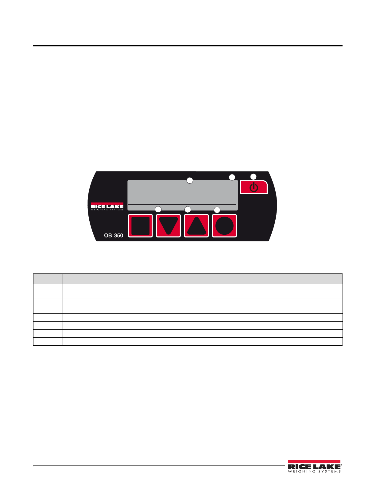
2.1 Front Panel
The four symbol keys: square, down arrow, up arrow and circle on the keypad are assigned in both operator and
setup modes, and are used to navigate through the menus as indicated by the text or symbol in the OLED display.
Weight readings are in lb.
Operator Mode
and serial number appear in the 10 second
the vehicle is static and on level ground.
ZERO to return the display to 0 lb when the
Figure 2-1. Operator Mode
Key Description
A Print key - prints net, gross, time & dat
Acts as an accumulation button
B When the vehicle is completely empty and in th
adjust the display to read ‘00000’, up to 1100 lb.
C MENU key - scrolls through’ NET, GROSS, MENU & any options activated.
D Displayed weight.
E Shows active function or weighing mode.
F Power button.
e in weighing screens when activated.
in load/deliver mode.
e weighing position, the front panel ZERO or TARE can be used to
2 OB-350 Indicator Operator’s Manual
Page 7
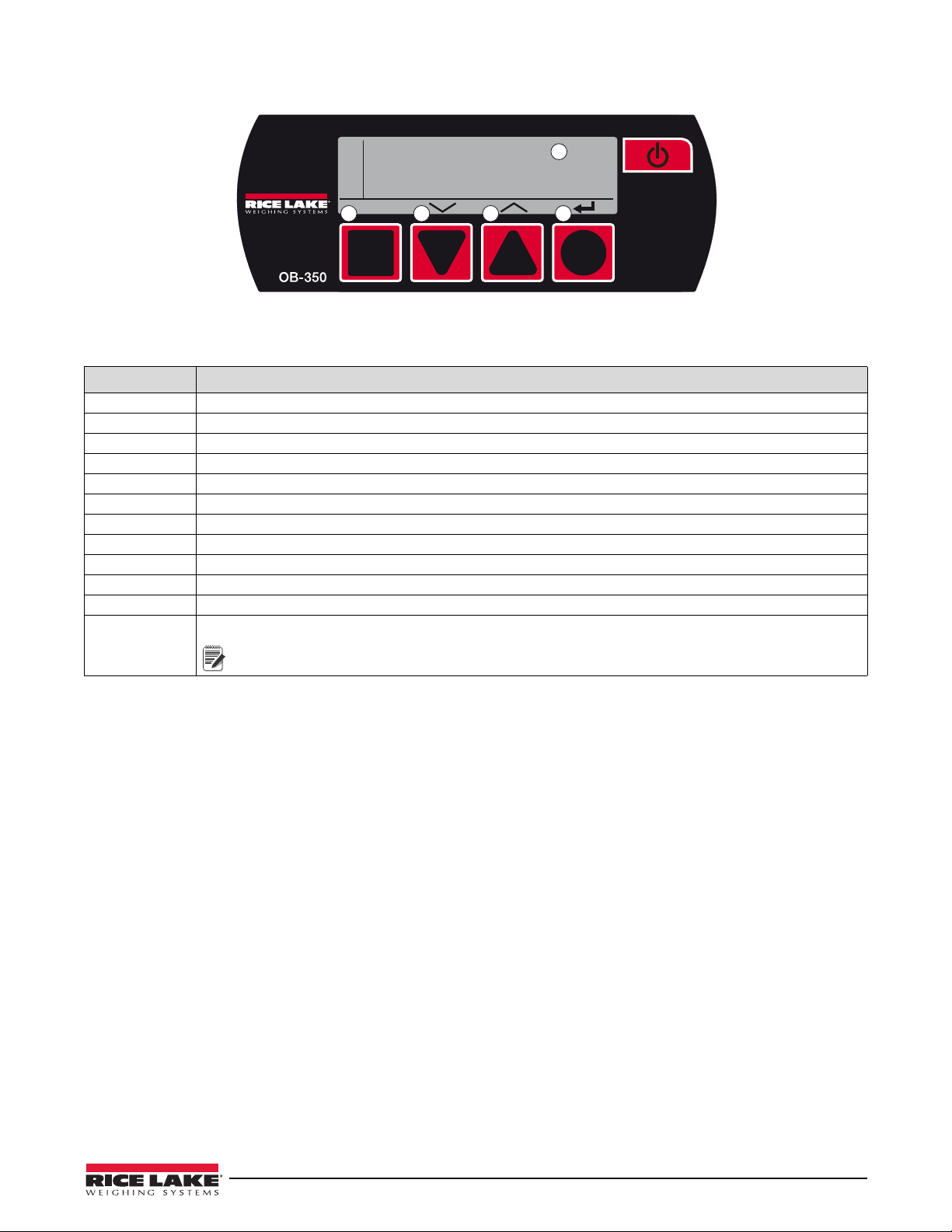
Operator Configuration and Technician Setup Menu
M
E
N
U
(OK)
Display
Diagnostics
Alarms
Options
Configuration
Calibration
System
A B C D
E
Note
Figure 2-2. Setup Mode
Key Description
A OK key - acts as enter or accept key.
B Down arrow key - scr
C Up arrow key - scrolls up menu.
D Back-up key - goes back a step (in some modes, acts as enter or accept key).
E Selectable MENU options.
Display Changes OLED contrast to high, medium or low. Also shows
Diagnostics Shows two channel weights, input mV signals & CANbus connections.
Alarms Two alarm set points - PIN code required to mute Alarm - press any key.
Options Activates options and changes settings.
Configuration Selects 1 channel, or 2 channel, air, oil or fifth wheel, split axle systems, etc.
Calibration Weighing system calibration settings, Tare, Zero & Span.
System Accesses password set and resets.
For PUK (PIN unlock code) contact RLWS service to for instructions through your PIN
retrieval.
olls down menu.
software version and serial number.
Operation 3
Page 8
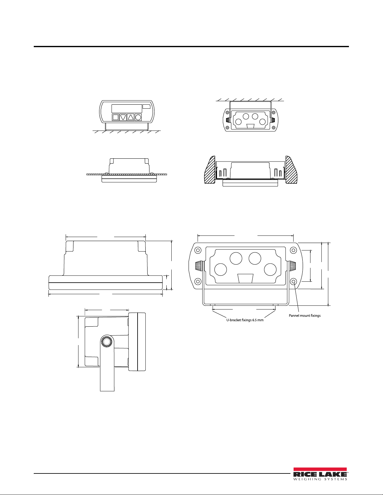
3.0 Installation
Panel mount
Roof/under dash mount
Dash mount
Optional Radio DIN mount
145
18
62.5
100.5
59
90 centres
dia holes 2 places
122 centres
4 mm self taper
3.5 deep - 4 places
90
40 ctrs
44
145
Locate the most convenient place for mounting the indicator. When atta ching the u-bracket, ensure there is
adequate headroom. The cables will be wired into the back of the indicator, so make sure to allocate enough space
for them during installation.
3.1 Mount Options
Figure 3-1. Mounting Options
3.2 Dimensions
Figure 3-2. Dimensions
4 OB-350 Operators Manual
Page 9

3.3 Electrical Wiring and Data Connections
1
3
2
4
5
6
12B1D4FB
T
The OB-350 is fitted with one Power and one Input Channel connector as standard. CANbus, Channel 2 and RS-232 are optional.
Full connector options is shown for illustration.
Figure 3-3. Rear Panel Identification and Bulkhead Connectors
Pin Description
1 Input Channel 1, Max +/-39.0625 milli-Volts (also known as analog)
2 Input Channel 2, Max +/-39.0625 milli-Volts (also known as analog)
3 Power Input & Alarm Output
4 CANbus digital input & output
5
6
RS-232 output for printers and data captur
receive)
Alpha-numeric unique indicator serial number, also appears on power-on
e devices (pin 9 = vehicle volts, pin 5 = ground, pin = 2 transmit, pin 3 =
SIGNAL channel 1 & 2, socket is FEMALE. – CON 2 & 3 on PCB
Pin 1
Pin 2
Pin 3
Pin 4
BROWN + Excitation 5 Volts DC
WHITE + Signal milliVolts from the junction box & loadcells
BLUE - Excitation 0 Volts
BLACK - Signal milliVolts from the junction box & loadcells
POWER & ALARM, socket is MALE – CON 1 on PCB
Pin 1
Pin 2
Pin 3
Pin 4
BROWN Vehicle voltage Supply 12V (LCV) or 24V (MCV & HGV)
WHITE Output 1 12V or 24V
BLUE Ground Ground 0 Volts (common)
BLACK Output 2 12V or 24V
CANbus input and output, plug is MALE – CON 5 on PCB
Pin 1
Pin 2
Pin 3
Pin 4
BROWN +24V +24 Volts DC Power Input
WHITE GND CAN bus LOW Output
BLUE CANH 0 Volts Ground
BLACK CANL CAN bus HIGH Output
Installation 5
Page 10

3.4 Cables and Connectors
FEMALE moulded plug
POWER & ALARM
supplied as standard
MALE moulded plug
SIGNAL & CANbus
supplied as standard
MALE rewirable plug
SIGNAL
part no CBL0038
FEMALE rewirable plug
POWER + ALARM
part no CBL0039
Junction boxes
have FEMALE
signal sockets &
MALE indicator
cable socket
LoadRunner connectors have keyways and are gendered and thumb tightened for ease of use. System kits are
supplied with fully molded connectors. Rewirable plugs are available for replacements or repairs. The RS-232
connector is industry standard. This manual also shows interchangeable rewirable plugs.
Figure 3-4. Connectors
RLWS cables and connectors are specially designed to provide maximum signal strength and reliability.
Substitution of cabling other than RL WS supplied cabling may cause inconsistent and erratic readings. Care should
be taken when routing cables to provide protection from sharp edges, drive-line rotation, exha ust pipe, or any o ther
potential damage. Secure in place with cable ties to a snug fit. Locate the junction box mid-chassis at a suitable
accessible position and fix firmly with screws supplied.
6 OB-350 Operators Manual
Page 11
4.0 Operating Modes
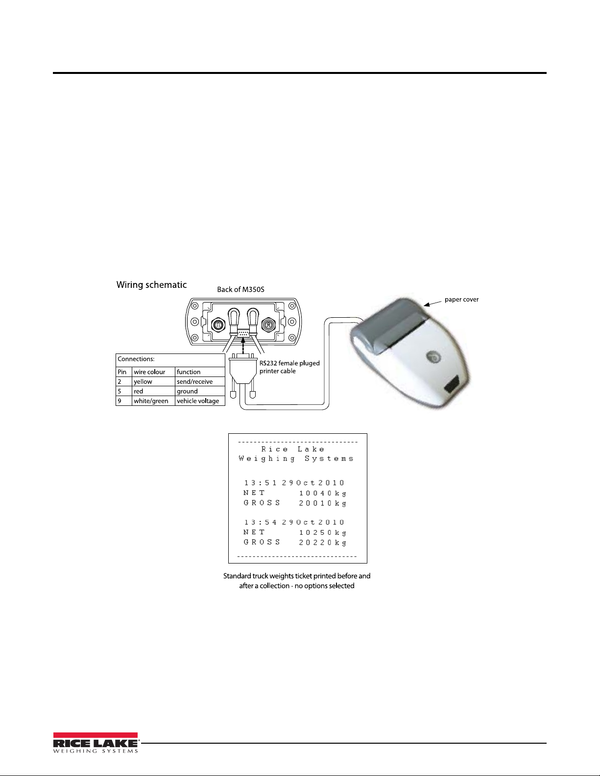
4.1 Printing & Print Tickets
Ensure the RS-232 option is set to PRINTER and a printer is connected with the cable supplied. The printer is
powered through the RS-232 connector and uses a default baud rate of 9600. There are three print tickets available:
4.1.1 Truck Weights
Press print.
Net, gross, time and date is printed
4.1.2 Load Mode
Press print in load mode.
Time & date together with individual and total bin collections from a site and truck information is printed.
This mode can also be used with the additional keyboard to enter an account number for the site.
Figure 4-1. Wiring Schematic
Operating Modes 7
Page 12

4.2 Load Mode
Note
Note
4.2.1 Operator Instructions
Load/Deliver Function
With the load/deliver function turned on, the driver has acce ss to the load/deliver and total screen. This function
allows tracking of the print and accumulate transactions for a load (increase in weight) or delivery (decrease in
weight).
The OB-350 is designed to only accumulate a positive value, either load or delivery.
1. To activate, while in the load/deliver screen, select the ON Site key.
The function keys perform the following:
• Off – turns off load/deliver accumulation mode
• Print – accumulates displayed weight in total value, prints t
• Zero – allows the display to be zeroed.
Total Driver Display
With the load/deliver function on, the total display will continue to accumulate the weight value. To clear the total
weight value, press the zero key.
Zeroing the total display will not affect the load/delivery accumulation window.
and clears the totals accumulation.
icket if printer is attached.
8 OB-350 Operators Manual
Page 13

5.0 Operator Configuration and Diagnostics
Note
OptionsAlarms
Alarm 1
Alarm 2
Cells
CAN
Diagnostics
Menu
OLED
Info
Display
Split
Input 2
Input 1
Configuration
Span
Zero
Tare
Calibration
Modes
RS-232
PRINTER
Count
1 lb
10 lb
20 lb
50 lb
100 lb
200 lb
INC
ON
OFF
System
PUK
Pin
Clock
Net
Gross
Net & Gross
ON
OFF
Chan
Load
Z/Func
Keyboard
Inhibit
Keyboard
Printer
Printer CSV Data
Printer G PVWS
None
Format 1-4
Scoreboard
Net 4
Gross 4-5
G PVWS
BA4840
5.1 User and Setup Menu
The menu structure has two levels of security: an open user menu for driver operators and a password setup menu
for calibrations and options for making changes to the user menu.
The default password is 0350. Keep this for your records.
User and Setup Menu
Parameter Choices
Display OLED
Diagnostics Cells
Alarms Alarm 1
Figure 5-1. User and Setup Menu – Electrical Wiring and Data Connections
Info
CAN
Alarm 2
Adjust the brightness of the display; High, Med or Low.
Firmware version and serial number display.
To display mV/V for load cells or transducers on seperate channels.
To display CANbus diagnostics (not used).
Allows configuration of audible alarms.
Description
Operator Configuration and Diagnostics 9
Page 14

User and Setup Menu
Parameter Choices
Description
Options Modes Select weighing mode to be displayed - Net. Gross or Net & Gross.
Load/Chan Load function gives the option to accumulate the amount of load (weight) delivered or
collected from site.
Channel Function - Split screen function is added to the MENU screen (for semi trucks only).
RS-232 Select or change RS-232 output option.
Count Select count by in lb - 1, 2, 5, 10, 20, 50, 100, 200,
Z/Func Allows operator access to Zero/Tare function on the display.
Inc For use with roll off systems and dump trucks, turn on to calibrate zero degrees of
inclinometer.
Configuration Input 1(F)
Input 2 (R)
Split
CAN
Calibration Ta re
Zero
Span
System Pin
PUK
Clock
Air/Oil pressure transducer or load cell setting based on truck type.
Air/Oil pressure transducer or load cell setting based on truck type.
Setting varies depending on input 1/input 2 values.
Not Used
Entry of empty vehicle weight for gross weight calculation.
No load zero calibration.
Entry of load for span calibration.
Enter a password.
Not Used.
Change system time and date.
10 OB-350 Operators Manual
Page 15

5.2 Operator Settings
lb
Milli-Volt readings will differ according to the combined tare (empty)
weight and any payload in the body. Load cells should only be checked
when the vehicle is unloaded. Max input reading is 39.625 milli-Volt, this
is approx 10 times more than would be expected.
Note
5.2.1 Display Menu
To change the display contrast
1. In MENU, select Display.
2. Press (OK).
3. Select OLED.
4. Press
5. Press toggle between:
6. Press to confirm setting.
To display version and serial number
1. In MENU, select Display.
2. Press (OK).
3. Select
4. Press
5. Firmware version and serial number displays.
6. Press
(OK).
High
Medium
Low.
Info.
(OK)
twice to return to MENU
5.2.2 Diagnostics Menu
To Display Load Cell Diagnostics
1. In MENU, select Diagnostics.
2. Press (OK).
3. Select Cells.
4. Press (OK).
5. Ch a n n e l 1 & 2 weight and input mill-Volt readings are dis pl ay ed . Channel
1 only is the most common setup.
6. Press
To Display CAN Diagnostics
Not currently available.
twice to return to MENU.
Operator Configuration and Diagnostics 11
Page 16

6.0 Technical Settings
Symbols
Keys
Password or PIN is needed for every calibration & calibration change.
PIN codes can be reset to a new code of your choice, select Reset and
repeat steps. This is not recommended, loss of custom password will
require serial number of unit and may take up to 48 hours to process the
code.
Note
Important
6.1 Calibration and Setup
To allow for on-vehicle installation variations, an initial and periodic system calibration is required. The first
calibration should take place a couple of weeks after the onboard weighing system has been used in service.
(OK)
When selecting symbol, press the corresponding key below the symbol.
6.2 System Menu
6.2.1 Entering Pin Code (Password)
1. In MENU screen, select System.
2. Press
3. Press to select Pin.
4. Press
5. Enter default password 0350.
6. Press
7. Press
8. Press
9. To Set PIN, select PIN, press
(OK).
(OK) to display PIN input screen.
• Press
• Press
or to number 0-9.
to move cursor left.
to enter code.
(OK) to accept the password.
to back up to MENU.
(OK) and repeat 2 - 6.
6.2.2 Entering PUK Code
For use if a custom password is used, which is not recommended.
1. In SYSTEM screen, select PUK.
2. Press
3. Call RLWS at 800-472-6703 and give
4. Press
5. Press
6. When PIN is entered press
12 OB-350 Operators Manual
(OK). PUK code enter screen and unique PIN reset code is
displayed.
the unique five-digit number
disp layed. RLWS wi l l prov ide a NEW four digit PIN code.
or to number 0-9.
to move cursor left.
to enter code.
Page 17

6.3 Alarms Menu
lb
lb
lb
lb
lb
lb
lb
lb
lb
lb
lb
lb
lb
lb
lb
6.3.1 Alarm Setpoints
Allows configuration of the audible alarm.
Parameter Choices Description
Alarm Alarm ON Tur n s a l arm o n .
Alarm OFF Turns alarm off.
Output Output Normal +12 VDC to power and alarm on power connector.
Output Invert -12 VDC to power and alarm
Gross Gross PPCO Not used (custom packer-pla
Net Sounder Alarm will display speaker and beep when net weight
eaches Alm value entered.
r
Net PPCO Not used (custom packer-pla
Inc Sounder For use with inclinometers onl
angle reaches above incline (inclinometer setting) in
degrees.
Inc PPCO Not used (custom packer-pla
Gross Sounder Alarm will display spea
reaches Alm value entered.
Alm Alarm Weight
lu e
Va
Hys Hysteresis Value Not currently available.
Tri gg er Off
On 2,5,10 seconds – selectable delay prior to alarm
Edit value of the net or gross weight for alarm.
ctivating in seconds.
a
Table 6-1. Alarm Setpoints Menu
on power connector.
te configuration only).
te configuration only).
y – activates alarm when
te configuration only).
ker and beep when gross weight
6.3.2 Set Alarm
1. In MENU, select Alarms.
2. Press
3. Two setpoints appear. Select Alarm 1.
4. Pressing
5. Pressing
6. Pressing
Gross-PPCO or Net-PPCO.
7. Select
weight displayed. To change target weight, press
setpoint using techniques in previous steps.
8. Select
9. Select
10. When all settings are correct, press
11. For alarm 2, select
(OK)
(OK) toggles between ON and OFF. Select ON.
(OK) toggles between Output Normal and Output Invert.
(OK) toggles between Gross-Sounder, Net-Sounder,
Alm. The alarm (sounder or flashing beacon) will activate at
HYS, reset tolerance is edited in lb using techniques in previous steps.
Trigger, then press (OK) to toggle between: OFF, 2, 5 or 10 seconds.
Alarm 2 and repeat steps 7-10.
edit and set the alarm
(OK) to confirm.
Technical Settings 13
Page 18

6.4 Options Menu
lb
lb
6.4.1 Select & Change NET, GROSS OR BOTH
Configuration of this setting will turn on visible weight screens in the standard
operator mode. Use the menu key to scroll between settings.
1. In MENU, select
2. Press
(OK).
3. In OPTIONS menu, select Modes.
4. Press
(OK).
5. In MODES menu, press to toggle between:
NET & GROSS
GROSS
NET
NET & GROSS is the common option.
6. Press
to confirm setting.
6.4.2 Load/Channel
The load option allows the load/deliver function to be turned ON and OFF.
When turned on, the load/deliver screen and totals
mode.
Options.
screen will be available to the driver during normal operating
Parameter Choices Description
Load Load On Activate the load/delivery function
Chan On For Semi-Trucks only, currently not used.
Load and Chan On For Semi-Trucks only, currently not used.
Load and Chan Off Deactivate the load/delivery function
Table 6-2. Load Menu
Turn Load Option ON and OFF
1. In MENU, select Options.
2. Press
(OK).
3. In OPTIONS menu, select Load.
4. Press (OK).
5. In LOAD option press to toggle between settings.
on the driver display.
on the driver display.
14 OB-350 Operators Manual
Page 19

6.5 RS-232
lb
6.5.1 To Select and Change RS-232 Output Options
1. In MENU, select Options.
2. Press
3. In OPTIONS menu, select RS232 and press (OK).
4. Press toggle between:
(OK).
Printer - printer setup (standard printer setting)
Printer CSV (comma, space, value) Data
Printer GPVWS (not used)
None
Scoreboard Format 1 (remote display)
Scoreboard Format 2 (not used)
Scoreboard Format 3
Scoreboard Format 4 NET (not used)
Scoreboard Format 4 GROSS (not used)
Scoreboard Format 5
Scoreboard Format 6 GPVWS (not used)
Scoreboard Format 7 BA484D (not used)
5. Press to confirm setting.
6.5.2 RS-232 Output Options
• OB-350 Scoreboard Output
• Baud Rate is fixed at 9600,n,8,1
• Data is sent out every 1 second (formats 1, 3 & 4)
• RS-232 - 9 Way ‘D’ Male Plug
Pin Function Notes
1 -
2 Tx
3 Rx
4 -
5 Gnd 0V Ground
6 -
7 -
8 -
9 +24V Vehicle Supply
Transm i t F r o m
Receive into
OB-350
OB-350 (not used)
Technical Settings 15
Page 20

6.5.3 Scoreboard Format 1
ASCII = Character code set 0-127
click: danshort.com/
ASCIImap/
CR = Carriage Return
LF = Line Feed
STX = Start of the text
STA = Status
SGN = milli-Volt load cell Signal
ETX = End of text
U/S = Unspecified
CNT = Count
CHK = Checksum
Tx = Transmit
Rx = Receive
Note
Used for remote displays.
Data output is the NET weight in ASCII + CR and LF
Example
NET 2160 kg
NET 2200 kg
NET 2200 kg
NET 2180 kg
NET 2180 kg
NET 2180 kg
NET 2180 kg
6.5.4 Scoreboard Format 2
Requesting Device sends ASCII command:
“20050026:<CRLF>”
M350S replies
“9F050026: 15.71 t G <CRLF>”
Example:
“9F050026: 15.71 t G <CRLF>”39 46 30 35 30 30 32 36 3A 20 20 31 35 2E
37 31 20 74 20 47 0D 0A
6.5.5 Scoreboard Format 3
Data is output in the following format:
<STX(1)> <STA(1)> <SGN(1)> <PAYLOAD(7)> <UNITS(3)> <ETX(1)>
STX = 0x02 Start of text
STA = “N” Status - N represents NET weight
SGN = 0x20 or “-” Sign – space = pos, minus sign = negative
PAYLOAD Weight – next 7 characters are weight in ASCII
UNITS = “ kg” Units
ETX = 0x03 End of text
Example:
16 OB-350 Operators Manual
(Net weight 15000 kg) 02 4E 20 20 20 31 35 30 30 30 20 6B 67 03
(Net weight 5045 kg) 02 4E 20 20 20 20 35 30 34 35 20 6B 67 03
Page 21

6.5.6 Scoreboard Format 4
(NET / GROSS)
Data is output in the following format:
<STX(1)> <U/S(3)> <CNT(1)> <U/S(5)> <PAYLOAD(3)> <CHK(1)>
STX = 0x01 Start of text
U/S = (3 bytes) Unspecified – 3 bytes do not use
CNT = hex val Count – Incremental message count, from 0x00 to 0xFF hex
U/S = (5 bytes) Unspecified – 5 bytes do not use
PAYL O A D = (3 bytes) Weight – 3 characters of weight value in hex (note1)
CHK = hex val Checksum – longitudinal checksum value not including STX
Example:
Messages with weight 18520 kg (0x004858)
Select the weight value either NET or GROSS in the M350S set-up.
01 00 0A 81 BE 01 01 00 01 00 00 48 58 EC
01 00 0A 81 BF 01 01 00 01 00 00 48 58 ED
01 00 0A 81 C0 01 01 00 01 00 00 48 58 EE
01 00 0A 81 C1 01 01 00 01 00 00 48 58 EF
6.5.7 Scoreboard Format 5
Data is output in the following format:
<STX(1)> <SGN(1)> <PAYLOAD(7)> <STA(1)> <ETX(1)>
STX = 0x02 Start of text
SGN = 0x20 or “-“ Sign – space = pos, minus sign = negative
PAYLOAD Weight – next 7 characters are weight in ASCII
STA = “N” Status - N represents NET weight
ETX = 0x03 End of text
Example:
(Net weight 1 5000 kg) 02 20 20 20 31 35 30 30 30 4E 03
(Net weight 5045 kg) 02 20 20 20 20 35 30 34 35 4E 03
Technical Settings 17
Page 22

6.5.8 Scoreboard Format 6
Data is output in the following format every 60 seconds:
$GPVWS,<type>,<sgn>,<net>,<gvw>,<alarm1>,<alarm2>,<set1>,<set2>,HHMMSS,DDMTYY*XX
type = 01 Unit type 01 = M350S under body weigher: LOADWEIGH
sgn = “+” or “-“ Sign of Net – plus sign = positive, minus sign = negative
net Net weight – 5 characters
gvw Gross Vehicle Weight – 5 characters
alarm1 Alarm 1 set point – 5 characters
alarm2 Alarm 2 set point – 5 characters
Set 1 N = Net, G = Gross: S = Sounder, P = PPCO: 0 = not Activated, 1 = Activated
Set 2 N = Net, G = Gross: S = Sounder, P = PPCO: 0 = not Activated, 1 = Activated
HHMMSS Hours, Minutes and Seconds
DDMTYY Day, Month and Year
*XX Checksum
Example:
Net = 15000kg, gvw = 25000kg, alarm 1 Net sounder at 15500kg, alarm 2 Gross PPCO at 26000kg
$GPVWS,01,+,15000,25000,15500,26000,NS0,GP0,164100,280210*XX
Net = 15900kg, gvw = 25900kg, alarm 1 Net sounder activated at 15500kg, alarm 2 Gross PPCO at
26000kg $GPVWS,01,+,15900,25900,15500,26000,NS1,GP0,164200,280210*XX
6.5.9 Scoreboard Format 7
Data is output in the following format for interface with a BA484D Serial Display:
<CVn,string> Cyclic Variable
Parameters
n = 1 or 2 Input Variable number, where 1 = net & 2 = gross, string = any 7-bit numeric ASCII string
The <CV> Cyclic Variable is used to update the BA484D display with each variable indi vidually by sending the
numeric value as a simple ASCII string. The syntax is <CVn,string> where n represents the input variable to be
updated (= 1 or 2) and string is the numeric value to be displayed.
Example:
The command <CV1,123456.0> will set the input variable 1 (net) to a value of “123456.”
18 OB-350 Operators Manual
Page 23

6.6 Count by option
lb
lb
Note
lb
1. In MENU, select Options.
2. Press
(OK).
3. In OPTIONS menu, select Count
4. Press (OK).
5. Press to toggle between:
1 lb, 2 lb, 5 lb, 10 lb, 20 lb, 50 lb, 100 lb, 200 lb
6. Press to confirm setting.
Rice Lake Weighing Systems recommends using 50 lb minimum. Choosing a lower weight value may cause
your weight to fluctuate on the display and returning t
o zero may be difficult.
6.7 Zero Function
Allows the Zero key to be turned on or off when in normal weighing mode.
Parameter Choices Description
Z/Func Allow Keypad Zero Activate container tare (Gross Mode) or Zer
on main menu to allow operator to zero up to 1100 lb of weight.
Inhibit Zero Deactivate operator zero functionality.
Figure 6-1. Zero Function Menu
o (Net Mode) button
Turn Z/Func On and Off
1. In MENU, select Options.
2. Press (OK).
3. In OPTIONS menu, select Z/Func.
4. Press
(OK).
5. Press to select Z/Func setting.
6. Press
to confirm setting.
7. Zero is added to the MENU screen.
Technical Settings 19
Page 24

6.8 Inclinometer
lb
On dump trucks and roll off applications, the LoadRunner system uses load
pins and a hydraulic pressure transducer to determine a weight value. To
achieve the best accuracy, calibrate the system at the same incline that will be
used for determining the weight value, within ±1-2 degrees.
The inclinometer setup screen shows both
and absolute angle (abs 0.0). For this application, use the level indicators that
light up for every degree the body is raised.
The numeric value will indicate a negative value as the body is raise
normal. The level to the right will light up one circle at a time.
The inclinometer function allows visual determinatio
achieves to accurately weigh consistently.
6.8.1 Calibrate the Inclinometer
1. Ensure the truck is on a level surface and the body is in the down
position.
2. In MENU, select
3. Press
(OK).
4. In OPTIONS menu, select Inc.
5. Press (OK).
6. Press to select On.
7. Press
8. Press
9. Press
CAL to calibrate the inclinometer.
(OK) to confirm inclinometer zero.
to return to options menu.
Inclinometer screen will be added to the MENU options.
Options.
the body angle in a numeric value
d. This is
n of the height the body
20 OB-350 Operators Manual
Page 25

6.9 Configuration Menu – Input
Input one is channel 1.
Note
Transducers are load cells, oil & air pressure sensors, etc.
Note
The Input Channel configuration determines what type of truck the LoadRunner system is being installed on. Use
the following settings and instructions for each type of truck used. Configuring the system differently will affect
how the unit performs. The input channel referenced also references the connection on the back of the indicator.
Roll Off/Dump Truck Configuration Settings
Parameter Choices Description
Input 1 (F) Air/Oil Transducer Air or Hydraulic Pressure Transducer
Input 1 (R) Cell x 4 Load Cells
Split Channel 2 fix
Straight Truck Configuration Settings
Parameter Choices Description
Input 1 (F) Air/Oil Transducer Air or Hydraulic Pressure Transducer
Input 1 (R) Cell x 4 Load Cells
Split Single Channel Cal
6.9.1 Input Channel Configuration
1. In MENU, select Configuration.
2. Press
3. In CONFIGURATION, select
4. Press (OK).
(OK).
Input 1.
5. Warning message appears, press (OK) to continue.
6.
Press to select transducer type.
7. Press to confirm setting.
8. If Input Channel 2 is connected, select
Activating Input Channel 2 changes
Split to Dual.
Input 2 and repeat 4-7.
Definitions
•Input and Channel are used interchangeably.
•Transducers = load cells, oil & air pressure sensors,
•Split: single = One input channel, all transducers connected into
•Split: dual = Separate input channels, i.e. front
•Dual = Input channels 1 & 2 added together
fifth-wheel load cells, etc.
one junction box (in parallel)
and rear transducer sets are connected into the M350S
, the total weight of channel 1 & 2 will be displayed. Most VWS
load cells can be connected together in parallel as the milli-Volts signals are compatible. VWS load cells, oil
& air pressure transducers and fifth wheel load cells have different milli-Volt outputs and cannot be connected
into one junction box (with the exception of CANbus enabled sensors).
•Twin = Input channels 1 & 2 are displayed separately (e.g. the front a
nd rear of a vehicle). Separate calibrations
are required which require weighing the front and rear axle/s separately and entering the data.
Technical Settings 21
Page 26

7.0 Calibration
Truck Scale
Note
lb
22000
lb
lb
lb
lb
Drive empty truck onto the scale to determine empty weight. Perform span calibration.
For span calibration, use 3/4 of the full body load.
7.1 Calculating Tare, Gross & Net Weights
1. To determine actual TARE weight, run the empty vehicle onto a truck scale and note the total weight.
Figure 7-1. Vehicle on Truck Scale
2. Load the vehicle as close to its legal maximum as possible.
3. Weigh the Loaded Gross vehicle – run the vehicle across
weight.
4. Calculate NET weight using: Gross - Tare = Net.
5. Use the NET weight as the span weight
during the calibration procedure.
the same truck scale and record the Gross vehicle
7.1.1 Enter Tare Weight
1. Ensure vehicle is empty, then weigh and record TARE (empty
vehicle).
2. In MENU screen, select
3. Select
Tare.
4. Press (OK) (defaults to 22,000 lb).
5. Press
edit.
6. Enter vehicle TARE (empty) weight recorded in step 1.
7. Press
8.
Press again to return to MENU screen.
.
Calibration press (OK).
22 OB-350 Operators Manual
Page 27

7.1.2 Set Zero Calibration
lb
lb
lb
lb
lb
lb
lb
lb
62000
lb
Reverse ZERO/ SPAN (For Straight Trucks Only)
The reverse zero/span option allows the weighing system to be first
calibrated when the truck is full (swapping step 3 & 4), discharging its
load then performing calibration zero. You must be in single channel
mode: Ch1 only. See Section 7.1.4.
Note
1. Make sure the vehicle is empty and on level ground.
For dump trucks and roll off trucks, raise the body clear of the chassis
approximately three
2. In CAL menu, press
3. Press
4. Press
5. Press
6. Press
(OK).
cal.
(OK) to Confirm Ch 1 Zero.
to return to CAL menu.
to four degrees.
to select Zero.
7.1.3 Full Span (Net Load) Calibration
1. Load vehicle to its legal max and record GROSS weight.
2. Weigh and record the TARE (empty) vehicle.
3. Subtract the TARE (or KERB) weight from the GROSS weig ht t o giv e
the
SPAN (NET) weight.
31900 -12500 =19400 lb SPAN (NET) PAYLOAD
4. In CAL menu, press
5. Press
6. Press
7. Edit the SPAN (NET) weight, as in steps 1 & 2 above.
8. Press
9. Press
10. Pres s
11. Press
If the vehicle is a tipper, raise the body clear of the chassis.
to Span.
(OK) (defaults to 62,000 lb).
edit.
when done.
cal.
(OK) to Confirm Ch 1 Span cal.
twice to return to MENU screen.
Calibration 23
Page 28

7.1.4 Reverse Zero/Span
lb
lb
lb
62000
Z
S
Reverse Zero/Span is an alternative to Full Span Calibration. The reverse zero/
span is used to perform a simultaneous zero and span calibration with the
vehicle fully loaded. Y ou must be in single channel mode, ch1only.
1. Weigh and record the vehicle fully loaded.
2. Do a normal span cal 1 (actual span figures not important). See
Section 7.1.2
3. Empty the vehicle, weigh and record the TARE weight.
4. In SPAN menu, check and edit the SPAN figure if required bu t do
not pres
5. In CAL menu, press
s ‘cal’.
to select Zero.
6. Press
corner of display.
7. Press
8. Press
cal.
(OK) to confirm channel 1 Zero CAL.
9. Press
to activate zero/span. Reverse span figure shown top-right
to return to CAL menu.
24 OB-350 Operators Manual
Page 29

8.0 Appendix
8.1 Terms
The following abbreviations, phrases and terms used in this manual are widely used in the truck weighing industry.
ALARM An alarm sounder or flashing beacon (where fitted) will activate when
alarm set point is reached.
BOGY Refers to a group of axles fixed close to each other, also known as dual or tri-axles.
CHANNEL Is the Input Channel.
DUAL Input channels 1 & 2 added together, the total weight of channel 1 & 2 will be
displayed. Most RLWS load cells can be connected together in parallel as the milli-
volts signals are compatible. Load cells, oil & air pressure transducers and
fifth wheel load cells have different millivolt outputs and cannot be connected
into one junction box (with the exception of CANbus enabled sensors).
GROSS GVW or GMW (gross vehicle weight or gross mass weight) is the total truck
weight (NET + TARE).
HYS Hysteresis - gives the option to activate the alarm in a window range above
and below the alarm set point (an alarm reset tolerance).
INPUT The input channel load cell groups are connected to the INPUT.
LOAD Part load collected or delivered – press PRINT to print and zero the load,
weight collected is stored as an accumulation to NET & GROSS.
NET The payload weight in the truck body.
ON SITE When Load is turned ON in options, on site allows logging onto site and
off site for weighing loads collected from a site with multiple bins (waste only).
OUTPUT No rmal = +12 VDC to power and alarm, Output invert = -12 vdc to deactivate
(a packer plate).
PIN Personal Identification Number – password.
PPCO Packer-plate cut-off, refuse trucks only.
PUK Pin Unlock Code.
SPAN The NET weight used to calibrate the scale. It is the difference between
the tare (curb or empty weight) and the gross weight.
SPLIT DUAL Separate input channels, i.e. front and rear transducer sets are connected.
SPLIT SINGLE One input channel, all transducers connected into one junction box (in parallel).
TARE Means the weight of the empty (no load) vehicle.
TRIGGER This is a selectable time delay prior to alarm activation.
TRANSDUCER Load cells, oil & air pressure sensors, fifth wheel load cells etc.
TWIN Input channels 1 & 2 are displayed separately (e.g. the front and rear of a vehicle).
Separate calibrations are required which require weighing the front and rear axle/s
separately and entering the data.
ZERO Zero Functionality:
• No load zero, any minor discrepancies (+/-1100 lb) because the truck body has
‘normalized’, e.g. stresses and strains incumbent in the mechanical construction of the
truck has weakened and dissipated.
• Driver zero allows the driver to zero the weight taken from a site to allow the next site’s
printed ticket to show as a separate set of weighting transactions.
Appendix 25
Page 30

8.2 Troubleshooting
Note
8.2.1 Fusing
The OB-350 is fitted with a self-resetting thermal fuse. In the event of a fault or an electrical surge, the thermal fuse
will activate and cut power. The fuse will reactivate after a few seconds, once the fault has been removed. Trip
current is 300 mV or greater than 30 VDC.
Perform the following simple checks to
1. If the readings are incorrect, but consistency is high or low
2. If the weight values are erratic, check the power supply
replace the indicator.
3. If the indicator is found to be defective, remove
problem has not been isolated, continue with the troubleshoot procedures.
Recalibration at this stage could complicate the problem. However, once the problem has been identified and
corrected, it would be advisable to refer again to Section 7.0 for calibration details.
8.2.2 Diagnostics
The diagnostic tool displays the electronic signals coming in from load cells, sensors or CANbus enabled devices.
Values shown will vary according to tare weights, any load in the body of the vehicle and mechanical installation
integrity. Look for consistency, positive values, and pairs of cells showing similar or dissimilar readings. Typical
millivolts readings may range from 1 to 8 mV, (no load to full load).
8.2.3 Visual Checks
If no indicator defects can be found, the fault may be in the cables or lo ad cells. A v is ua l in sp ec ti on o f ca bl es f or
damage or chafing, crushing. Make sure the cables connections are secure and thumb tightened. Make sure
exposed connections are clean and dry.
determine that the system is working correctly.
, recalibrate the system.
(9-30VDC). If the power supply is functional,
and contact RLWS service for a replacement. If the
8.2.4 Load Cell checks
If the display still shows an erratic reading or unusual high reading, disconnect one load cell from the junction box and note
its effect on the display. If the display shows a significant impediment, the load cell is probably at fault and will need
replacing. If no significant improvement is noticed, reconnect the load cell and repeat the procedure for the remaining load
cells.
26 OB-350 Operators Manual
Page 31

Condition Cause
Note
No indicator display • Power cable disconnected
• Power connection fault
• Defective indicator
Erratic indicator readings • Erratic supply voltage - loose cables/connectors
• Defective cable or connectors
• Defective load cell/s
• Deffective indicator
• Loose load cell bolts
Incorrect weight readings
(not erratic)
Unable to calibrate • Top load cell mounting bolts too long to calibrate maximum weight
Unable to zero • Defective load cell
• Incorrect calibration
• Dirty connectors
• Defective cable
• Defective load cells
• Top load cell mounting bolts too long - always weighing light
• Body rubbing on the chassis
• Build-up of dirt or grit in the loadcell slot
• Loose or broken connectors
Table 8-1. Troubleshooting Chart
Your RLWS LoadRunner system should be serviced & re-calibrated annually.
Appendix 27
Page 32

Hardware Warranty Statement
Rice Lake Weighing Systems (RLWS) warrants that all RLWS brand equipment and systems properly installed by
a Distributor or Original Equipment Manufacturer (OEM) will operate per written specifications as confirmed by
the Distributor/OEM and accepted by RLWS. All systems and components are warranted against defects in
materials and workmanship for two (2) years, unless otherwise stated.
RLWS warrants that the equipment sold hereunder will conform to the current written specifications authorized by
RLWS. RLWS warrants the equipment against faulty workmanship and defective materials. If any equipment fails
to conform to these warranties, RLWS will, at its option, repair or replace such goods returned within the warranty
period subject to the following conditions:
Upon discovery by Buyer of such non-conformity, RLWS will be given prompt written notice with a detailed
explanation of the alleged deficiencies.
Individual electronic components returned to RLWS for warranty purposes must be packaged to prevent
electrostatic discharge (ESD) damage in shipment. Packaging requirements are listed in a publication, "Protecting
Your Components From Static Damage in Shipment," available from RLWS Equipment Return Department.
Examination of such equipment by RLWS confirms that the non-conformity actually exists, and was not caused by
accident, misuse, neglect, alteration, improper installation, improper repair, or improper testing. RLWS shall be the
sole judge of all alleged non-conformities.
Such equipment has not been modified, altered, or changed by any person other than RLWS or its duly authorized
repair agents.
RLWS will have a reasonable time to repair or replace the defective equipment. Buyer is responsible for shipping
charges both ways
In no event will RLWS be responsible for travel time or on-location repairs, including assembly or disassembly of
equipment. Nor will RLWS be liable for the cost of any repairs made by others.
Installer is completely responsible for the design and fitting of the installation, and any changes which might result
in voidance of the warranty of the manufacturer of equipment to which the products are installed.
THESE WARRANTIES EXCLUDE ALL OTHER WARRANTIES, EXPRESSED OR IMPLIED,
INCLUDING WITHOUT LIMIT ATION WARRANTIES OF MERCHANTABILITY OR FITNESS FOR A
PARTICULAR PURPOSE. NEITHER RLWS NOR DISTRIBUTOR WILL, IN ANY EVENT, BE LIABLE
FOR INCIDENTAL OR CONSEQUENTIAL DAMAGES.
RLWS AND BUYER AGREE THAT RLWS' SOLE AND EXCLUSIVE LIABILITY HEREUNDER IS
LIMITED TO REPAIR OR REPLACEMENT OF SUCH GOODS. IN ACCEPTING THIS WA RRANTY,
THE BUYER WAIVES ANY AND ALL OTHER CLAIMS TO WARRANTY.
SHOULD THE SELLER BE OTHER THAN RLWS, THE BUYER AGREES TO LOOK ONLY TO THE
SELLER FOR WARRANTY CLAIMS.
No terms, conditions, understanding, or agreements purporting to modify the terms of this warranty shall have any
legal effect unless made in writing and signed by a corporate officer of RLWS and the Buyer.
© Rice Lake Weighing Systems, Inc. Rice Lake, WI USA. All Rights Reserved.
RICE LAKE WEIGHING SYSTEMS • 230 WEST COLEMAN STREET • RICE LAKE, WISCONSIN 54868 • USA
28 OB-350 Operators Manual
Page 33

Page 34

230 W. Coleman St. • Rice Lake, WI 54868 • USA
U.S. 800-472-6703 • Canada/Mexico 800-321-6703 • International 715-234-9171 • Europe +31 (0) 88 2349171
www.ricelake.com www.ricelake.mx www.ricelake.eu www.ricelake.co.in m.ricelake.com
© Rice Lake Weighing Systems 04/2014 PN 160914
 Loading...