

Page 1

Specs no. D-F0446
Provisional version
Product Specifications
2 & 3-inch Super High Speed Kiosk Printer
NP-2511
NP-3511
Revision 0.01 2006.11.30 Provisional version
Revision 0.07 2007.05.21 Provisional version
※Since the product is under designing, the specifications described can be changed.
※All specifications of 2-inch version is the provisional.
All specifications described are subject to change without prior notice.
Though we made assurance dubly sure to write this product specifications,
Please contact us if you find foul play, mistake and erroneous omitting.
Nippon Primex Inc.
Head Office:
1-5-12 Unoki Ohta-ku Tokyo 146-8650 Japan
TEL :+81-3-3750-1234 FAX :+81-3-3750-4555
E-mail : overseas@primex.co.jp
URL : http://www.primex.jp
D-F0446 NP-2511/3511 series Specifications Ver.0.07
Page 2
Record of Revision 1
Rev. V.
0.01
page item change
Pv
New release (prov.) Abe
0.02
Pv
3 Print Speed
0.03
Pv
25)engine motor Added Abe
Descriptions
Deleted page/line mode and
mentioned MAX.200mm/sec
approval PIC
2006.11.30
Abe
2006.12.13
1 Features 12) * added test schedule 2006.12.26
3 Print Speed Condition Optimized to drive
6
9、10
Consumption current conditon
Receiption control signal
Optimized to drive
Integrated to RTS
15 Select drive Optimized to drive
Optimized to drive
19~
45~
Command Added
Character code table Added
atch Kanji code table Added
atch
atch KSX1001-1992 Added
0.04
Pv
Chinese(GB18030-200)
1
Outline option (in review)
Added
Factory setting、 added black mark sensor
Abe
1 Feauters 12) * delete test schedule 2007.01.24
3 Print speed condition Added storage mothod
Ratio for print 50%→less than 50%
4 Print mode, page mode Added under development
4
5
Operating environment Temparature
Print area & Cutting Positoin
Changed -20~60→-20~45
Changed 3→2
Changed 12.5→11.5
5
7
7
Print area & Cutting Position
Operating environment Specs temparature
Operating environment Specs
Added *Preprint
Changed -20~60→-20~45
Changed testing→retesting schedule
Added next production
7
Storage environment Specifications Changed testing→retesting schedule
7 Safety standard Changed standard
7 UL60950-1 Changed approved
9 Interface USB Delete inspect *4)
11 4)CN7:Presenter Delete except NPT-301
Added NPT-305/NPO1201
12 Momory switch Added M2-6 option select
13
Memory switch manual setting
Added
13 Fig.3 Language font Added MS2
13 Seft Print
Changed Korean→Chinese
Changed Chinese→Korean
Changed control~function→control~operation
Deleted printer mechanism function
Deleted print quality
Deleted printer mechanism auto
14 Cutter abnormal status Deleted not-connect
14 Cutter abnormal cancell
14
Blackmark detective error
14 Presenter abnormal Added
Changed thermal head cover open
Deleted
D-F0446 NP-2511/3511 series Specifications Ver.0.07
Page 3
Record of Revison 2
Rev. V
0.04
pv
page item change
16
ALARM display pattern
Descritpion
Deleted Recovery Abe
Approved PIC
Added paper near empty 2007.01.24
19、35
19、38
Macro definition start/finish
Deleted
Macro excution Deleted
20
Command table Added *print method
31 Raster image bit Added serial interface
35
Black/white reverse printe set/reset
Changed download→Raster
36 Print start/end setting Changed fig. n(hex)
Changed print length 210→160
Deleted *Storage Print
Added *USB interface
39 Barcode Print
40 Print density set
Changed not barcode print over
Change stardard print desity~
Added Print start/finish~
0.05
pv
1 Option Added A:5 series blackmark Abe
Deleted blackmark in review 2007.02.08
5
Print area and cut position
Added specs of blackmark print
Added postion of partial cut
Added limited area
12 Memroy switch Changed MS2-6 revervation
14
Details of error detection
Deleted *MS2-6 option selection
Changed *MS2-6、MS2-7、MS2~
Added print start status
Added presenter abnormal→detected paper error
Deleted priority
16
16 FEED switch
19、32
20
ALARM Display pattern
Added priority
Changed Presenter abnormal→paper deted error
Deleted Cancel Mark detection
Detection blackmark Added
Plan to add~
deleted
31 Raster image bit Deleted serial interface
34 Printer status transmit
Presenter abnormal→detect paper error
Deleted Fig.
39
Print status auto-transmit
Changed Presentor abnorma→Paper detect error
Deleted fig.
0.06
pv
- NP-2511 Added provional specs. Abe
- Annotation
1
1
1
①paper size
②paper holder
④Option・OEM etc
Deleted 3 papers but recomended~
Deleted 7)low tempt.or highhumidity~
Deleted 24)preprinted~
Added 2:2inch(standard:58mm)
Changed 1:holder for roll paper
Deleted A:5 series blackmark
2007.05.01
D-F0446 NP-2511/3511 series Specifications Ver.0.07
Page 4
Record of Revison 3
Rev. V
0.06
1
page Item Change
pv
1 Feature Changed partly Abe
Feature 1)~3)
1 Feature 8)
Description
Consolidated in 1) 2007.05.01
Changed holder for roll paper
Approval PIC
2 constitution Added NP-2511
3 Specifications Added NP-2511
3 Print specifications
Separated in head specs and print specs.
3 Number of total dot Changed 576→640
3 Max. print width Changed 72→80
3 Number of print digit Changed max. print digit
Changed Font A 48→53
Changed Font B 64→71
Changed Kanji 24→26
4 Autocutter(partly) Move to other page
4 Paper Specifications Move to other page
4 Near empty Move to other page
4 Environmental Specs. Move to other page
5
Print area & cut position Changed Paper specifications
7 Print Area Added
8 Cutter Specs Added
9 Position of Blackmark Added
11 Consumption current
Separated 2 and 3 inch model
Ajusted supply voltage
Changed 25% 4→3.5
Changed 100% 15→14
11 Condition
Changed 2-fraction drive print
12 reliability Changed reliability Specs.
13 Environmental Specs. Added
19 Functions setting Added NP-2511
19 Memory Switch
Changed MS2-6 Mark sensor
Deleted MS2-6
26
26
27、36
27~
28、47
28、47
28、47
28、48
28、48
28
28
How to remove jammed paper
How to clean Thermal head
Back Feed
Detected Blackmark Deleted
Cue operaiton
How to detect mark and set the positioning offset
Set cue disposal when paper set
Set Print area
Set Max. print speed
*51)~53)Black~
*17)、51)~55) NP-
39 Raster Bit Image
0.07
pv
15
External measurement
Added *fig.NP-3511~
Changed 1)~4)
ADDED (NP-3511 F/W Ver1.10 and later)
Added(NP-3511F/W Ver1.10 and later)
Added (NP-3511 F/W Ver1.10 and later)
Added(NP-3511 F/W Ver1.10 and later)
Added(NP-3511 F/W Ver1.10 and later)
Added (NP-3511 F/W Ver1.10 and later)
Added
Added
Delete command~
Added NP-2511 Abe
2007.05.21
D-F0446 NP-2511/3511 series Specifications Ver.0.07
Page 5

Read Carefully Before Using the Printer
Wrong handling of the printer may cause its performance declined and the product damaged. Please read
the notes below before handling.
1. Static discharge prevention must be made for installation and removal of the printer to protect IC and
other electrical parts. Connect it to the earth ground. It is also requested to remove the static from body
of the person before handling, especially, the input terminal.
2. Avoid excessive force to the input terminal for handling.
3. Avoid printing with no paper loaded. It damages platen and thermal head, printer life will be shorten.
4. Do not scrabble thermal head with sharp edge or something hard, or give impact. The heat element
may be damaged.
5. Set the power of printer off before connecting or removing connecters.
6. The printer is not protected from water or dew formed. Do not water the printer or handle it with a wet
hand, which may cause damage to the printer due to short circuit, or heat or fire.
7. The printer is not protected from dust or dirt. If it is used at dusty place, the thermal head may be
damaged or paper feed is not operated properly.
8. When cooling the printer with a fan, avoid the printer’s paper outlet from locating fan’s air inlet. It may
cause mal-function of printer.
9. Reflection type of infrared ray sensors are used at some locations in the printer. Direct sun light may
cause mal-function of printer. Avoid from such a location for installation.
10. This printer does not support any operations caused by the commands or control commands not
specified in this manual.
11. Please use both hand when you hold the printer.
12. In order to prevent excess current, please put elemental device to external 24V power line (Please refer
to the power supply specification for the details), and also put fuse.
13. Please plug off the printer when you do not use the product for a long time. Please also insert paper
between the platen.
14. When paper jam occurred, please make sure to slowly remove the paper to paper exit direction after
head up status.
15. The product is designed to use with general electronic devices (Computer, PC, OA, others). This is not
designed and not guaranteed to use with extremely high quality, high reliability product or product whose
failure may danger human life (Atomic power control device, aerospace aircraft devices, Transportation
devices, Traffic signal devices, Ignition control devices, Medical devices, other safety equipments: we call
“Specific application” thereafter). Users take full responsibility for using with such specific application.
16. The product uses part that includes GaAS (Gallium arsenide). Please do not break the product, no
chemical splitting ,otherwise it may harm human with such part broken pieces.
17. The product should not be installed where it is tend to take place static easily, shaking strongly and
electromagnetic field, corrosive gas, rain, fog and direct sunlight.
18. There is some possibility that cut surface of steel plate on principal structural part of the product is to
rust easily.
19. Don’t re-create the product.
20. Don’t pull the paper while printing and paper-feeding. When thermal head cover is closed, don’t pull the
paper except for patial cut. When patial cut, you should pull either right or left on the edge of paper to
separate.
21. When you get rid of the proucting, you must dispose of according to local autholities.
22. In case the motor in engine of the product has been working for a long time or stopped and worked at
very short interval, the motor produces heat and doesn’t execised fully capacity. To avoid it, you should
get the motor stop for the same period of working time. The continuous working time is 6 minites one
time.
23. The coverage of warranty is limited within the product itself, Nippon Primex Inc is not responsible for
anything induced by the defect of the product, and don’t pay for any compensation.
D-F0446 NP-2511/3511 series Specifications Ver.0.07
Page 6

Table Contents
1. Overview·········································································································································1
1.1 Overview ·······························································································································1
1.2 Features ································································································································1
1.3 Configulations························································································································2
2. Specifications··································································································································3
2.1 Basic Specifications···············································································································3
2.2 Paper Specifictions················································································································5
2.3 Print Area·······························································································································7
2.4 Specifictions of Cutter············································································································8
2.5 Postion of Black Mark············································································································9
2.6 Power Supply Specifications ······························································································· 11
2.7 Reliability Specifications ······································································································12
2.8 Environment Specifications ·································································································13
2.9 Dimenssions························································································································14
3. Configurations ······························································································································16
3.1 Interface specifications : RS-232C ······················································································16
3.2 Interface specifications: USB (V2.0 Full Speed)··································································16
3.3 Connecter Signal Details ·····································································································17
4. Functions······································································································································19
4.1 Function Setting ··················································································································19
4.2 Processing error ··················································································································21
4.3 Buffer full print ·····················································································································21
4.4. Drive Select ························································································································22
4.5 Select Full size and half size character ···············································································22
4.6 Operation panel···················································································································23
4.7 How to set roll paper············································································································24
4.8 How to remove the jammed paper·······················································································26
4.9 How to clean Thermal Head ································································································26
5. Command·····································································································································27
5.1 Command Table ··················································································································27
5.2 Printer Driver ·······················································································································29
5.3 Command details·················································································································29
6. Character code table ····················································································································52
6.1 Domestic Character code table(International character set:Japanese)························52
6.2 Overseas character code(International set: USA)···························································53
6.3 CODE PAGE858 ·················································································································54
6.4 International character code table ·······················································································54
6.5 CODE PAGE1250 ···············································································································55
6.6 CODE PAGE1251 ···············································································································56
6.7 CODE PAGE1252 ···············································································································57
6.8 CODE PAGE1253 ···············································································································58
6.9 CODE PAGE1254 ···············································································································59
Appendix Kanji code table, Chinese(GB18030-2000)、KSX1001-1992
D-F0446 NP-2511/3511 series Specifications Ver.0.07
Page 7

1. Overview
1.1 Overview
Model name is specified as follows;
NP-3511
① ② ③
1. Paper Width (Factory Setting)
3: 3 inch ( Standard: 80mm)
2: 2 inch (Standard: 58mm)
* 2 inch in review
3. Interface (Factory Setting)
No mark: Serial (RS-232C), USB (V2.0 Full Speed) by user’s selection.
U : USB (V2.0 Full Speed) only.
4. Options or OEM etc.
No mark: original model (without option)
* Option: Bezel in review
1.2 Features
This model mounted with new developed small and low-cost in-house printer
mechanism is small and low-cost module printer for improving usability.
Installation at apparatuses has been finished with power supply (DC24V) and data
supply only, and this model can be used under the wide range of temperature
environment. Threrefore, the user can install this model freely. We can realize high
liability and quality by mounting in-house printer mechanism.
1) Small, light weight. Since this model is low-profile, it is easy to install on apparatuses
2) High Speed Printing & High Quality Printing
3) Interface available for Serial (RS232C) and USB (v2.0 High Speed)
4) Adaptation to various types of 1D barcode
5) Adaptation to various applications
6) Easy operational adjustable paper holder with detective sensor of near-empty
7) Drivers for various Operation Systems (optional)
Windows 2000/XP/CE5.0 Linux(sample)
8) Easy to re-write firm ware with Flash Memory & 3 patterns of registration available with
NV bit image.
9) Comply with Multiple Languages
10) Controllable external paper feeding(Presenter:NPT-301)
11) Easy to change roll paper by auto-loading
12) Wide range of operation temperature
U- *
④
2. Paper Holder Type (Factory Setting)
1. Holder for Roll Paper
D-F0446 NP-2511/3511 series Specifications Ver.0.07
1
Page 8

1.3 Configulations
model specifications Part# Q’ty NP-3511 NP-3511U
NP-3511 USB & Serial 70-00170-00 1 ○
NP-3511U USB only 70-00171-00 1 ○
Thermal roll paper W80xφ30(IDφ12) 24-00018-00 1 ○ ○
Model Specifications Part No. Q’ty NP-2511 NP-2511U
NP-2511 USB / Serial 70-00330-00 1 ○
NP-2511U USB 70-00331-00 1 ○
thermal roll paper W58xφ30(IDφ12) 24-00017-00 1 ○ ○
D-F0446 NP-2511/3511 series Specifications Ver.0.07
2
Page 9
2. Specifications
2.1 Basic Specifications
No.
Specifications 2 inch (tentative) 3 inch
1 Print head 1:Print method Line thermal dot
2:Total Dot 448 dots 640 dots
3:Dot density 8dot/mm
4:Print width (MAX) 56mm 80mm
2 Printing 1:Print speed(MAX)
conditions
*1
MAX.200mm/sec
Head temp.35℃and more、bufferful method
Optimized drive print ratio 50% or less
* except communication time
2:Max. print digit
Font A(12×24) 37 digit 53 digit
Font B( 9×17) 49 digit 71 digit
Kanji (24×24) 18 disit 26 digit
3:Paper feed pitch 0.125mm
3 Character 1:Character size
Font A(12×24) 1.50×3.00mm
Font B( 9×17) 1.13×2.13mm
Kanji (24×24) 3.00×3.00mm
2:Charactoers
Japanese
Korean
Chinese
Greek
Polish
Russian
Scandinavian
Turkish
Extended graphic character set(Half size)
Extended graphic character set(Half size)
JIS C 6226・1983(Full size)
Katakana character set(Half size)
Code Page 858(Half size)
International character set(Half size)
KS X 1001:1992(Full size)
Katakana character set(Half size)
Code Page 858(Half size)
GB18030-2000(Half/Full size)
Code Page 1253(Full size)
Code Page 1250(Half size)
Code Page 1251(Half size)
Code Page 1252(Half size)
Code Page 1254(Half size)
3:Character Double width
Modifications Double Height
Quadruple
Bold print
Double strike
Inverted
90°clock-wise rotaion
underlined
4:Line feed Q’ty (Default)
4.25mm (1/6 inch)
*1 Print speed fluctuates depending on the condition.
*2 KS X 1001:1992 Build-in Font
*2
*2
D-F0446 NP-2511/3511 series Specifications Ver.0.07
3
Page 10
No.
Specifications 2 inch (tentative) 3 inch
4 Print mode Line mode
Page mode (under development)
5
Barcode spec
1:1D Symbology UPC-A
UPC-E
JAN-13(EAN-13)
JAN-8(EAN-8)
CODE39
ITF
CODABAR
CODE128
6 inerface 1:Serial (dual tipe) RS232C compliance
2:USB(dual U type) V2.0 FULL SPEED compliance
7 Autocutter 1:cut mode Full/Partial cut
* by command selection
8
Receive buffer
Approx. 15K byte
9 Operation ALARM LED OUT
Switch input FEED Switch Input
Reset Switch
10 Appearance 1:Dimensions 106(W) x 150(D) x 127(W) x 150(D) x
Without connector&roll paper
75(H) mm 75(H) mm
2:Weight Approx. 640g Approx. 750g
Without roll paper
3:Mounting note*4 Horizetal Position Horizental Position
*3 Paper roll should be wind tightly. If not, can’t detect corectly.
Can’t detect near-end when you use wider core diameter than value set of near-end due to
reflective type photo sensor.
*4 This printer should be installed horizontally.
D-F0446 NP-2511/3511 series Specifications Ver.0.07
4
Page 11
2.2 Paper Specifictions
1) Printermechanism
2 inch (tentative) 3 inch
Paper wide 58/60-1mm 65/76/80-1mm
Paper thickness
65~150µm
・Do not change narrow paper to wide paper on using.(In case you use narrower paper
than wide of Thermal head, the uncovered part by paper on thermal head grazes
directly with palaten roller and the thermal head could be destoried.)
・In case you use paper wide 60, 65 and 76mm, please contact us. (Settnng of paper wide
for printers should be at Factory.
① Thermal Roll Paper Specifications.
a) External Dimensions of Thermal Roll Paper
max. external diameter:φ83mm
※Now we’d prepare paper holder PH-8L only. (uptoφ83mm)
When you use paper withφ84 and more, please contact us.
(In the case of using paper with φ100 and more, we adapt axis-suppot and
need additional cushion device.)
b) Paper Core Specificaitons
Paper thickness Inner core diameter Outer core diameter
65~85µm
100~150µm
φ12.0mm φ18.0mm
φ25.4mm φ33.4mm
※Width of paper core should be same as width of width of roll paper.
c) Conditions of using thermal paper
You should keep stricktly the following conditions;
・Do not stick end of paper with glue and scotch tape.
・The core of paper roll should not be deformed.
・The core of paper should not be sticked out over the side of paper roll.
・Don’t keep paper rolls on condition of heat and humidity
2) Paper Holder
① roll paper
Name Paper wide
PH-8L 80-1mm φ83mm
PH-10
* 1
-
External
diameter
φ83mm
Paper core Near Empty
Innerφ12.0mm
Outterφ18.0mm
Innerφ12.0mm
Outterφ18.0mm
φ22.0±2mm
φ22.0±2mm
* 1 Now PH-10 is under design for NP-2511.
By attaching the addional part, you can extend to Inner coreφ25.4mm、
Outer coreφ33.4mm.(in this case, we are confirming Near Empty.)
D-F0446 NP-2511/3511 series Specifications Ver.0.07
5
Page 12

3) Recommended Thermal Paper
Base paper # Paper thickness manufacturer Printing dentisy
PD160R
PD450-145
75µm
145µm
Oji Paper Co
Oji Paper Co
100%
5℃~60℃ :100%
-20℃~5℃ :120%
4) Remarks
・When printing on low temperature or high humidity on highly printing ratio, there is a
case that the recording paper get filthy due to water vapor generated from recording
paper and the printer builds up condensation. Please pay attention that a drop of
water doesn’t falls on thermal head. In the case of condensation, you should switch
off until the condemsation disappears. You should use the reliable and confirmed
fully thermal paper that has little Na+ ion, K+ion, Cl-ion.
D-F0446 NP-2511/3511 series Specifications Ver.0.07
6
Page 13
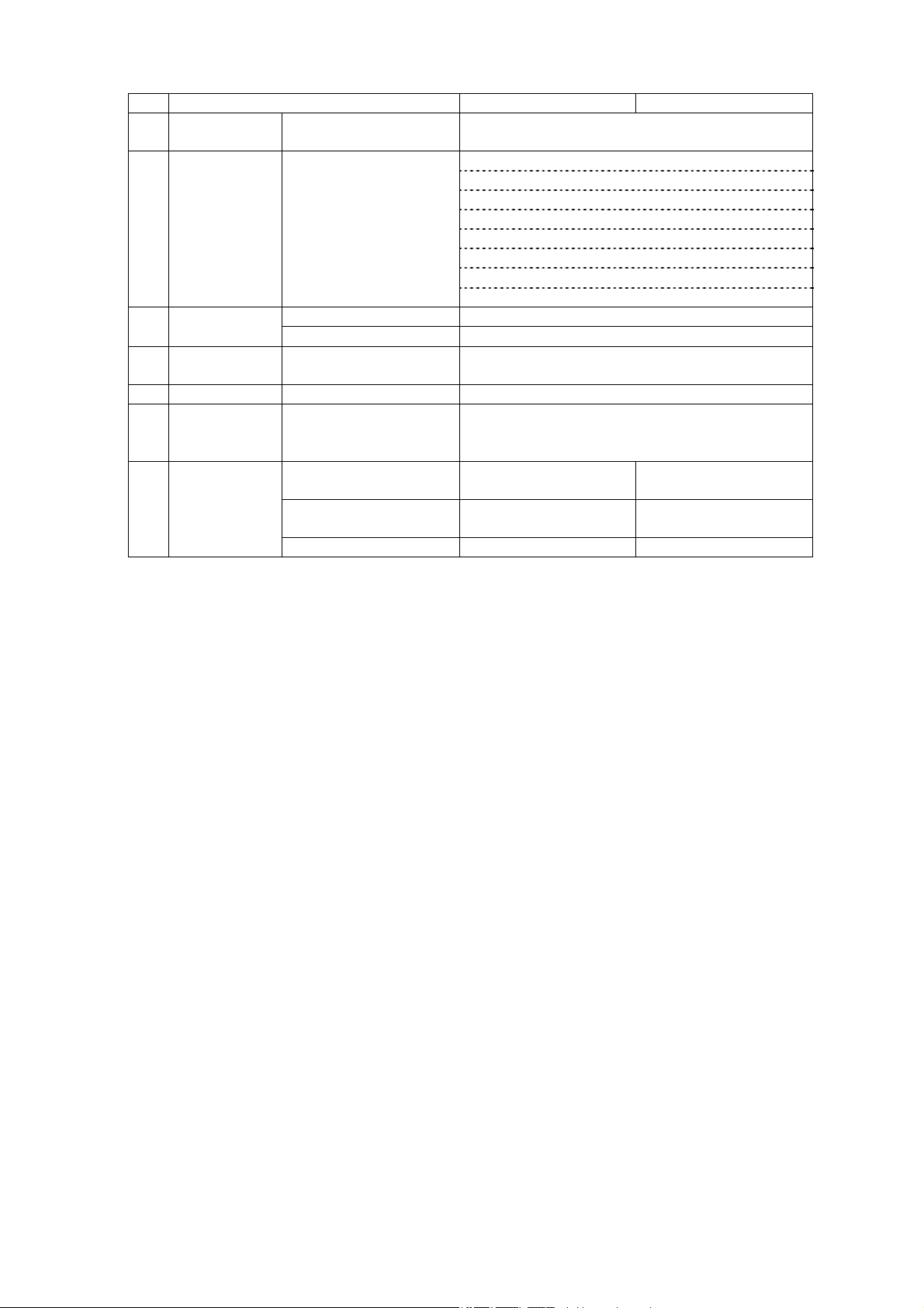
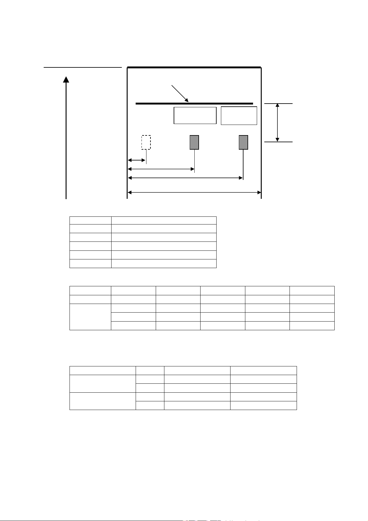
2.3 Print Area
Print Area
1) Name of Symbols
2) Paper Width and Example of Printing Area Setting
In case the margin on Left and Right is not enough, printing is run off due to directional
3) Factory Setting
Factory setting as follows:
Feed direction
Symbol Name
A The number of dot for Printing
B Left Margin
C Area of Printing
D Right Margin
E Paper Width
A(dot) B(±1mm) C(±0.2mm) D(±1mm) E(-1mm)
(tentative)
3inch
bias on paper. (We recommended more than 3mm) Printing Area can be changed by
command.
A(dot) B(±1mm) C(±0.2mm) D(±1mm) E(-1mm)
2inch
(tentative)
3inch
1dot 2dot
B
0.125mm
C
Adot
D
E
416 3 52 3 58 2inch
432 3 54 3 60
472 3 59 3 65
560 3 70 3 76
576 4 72 4 80
416 3 52 3 58
576 4 72 4 80
D-F0446 NP-2511/3511 series Specifications Ver.0.07
7
Page 14
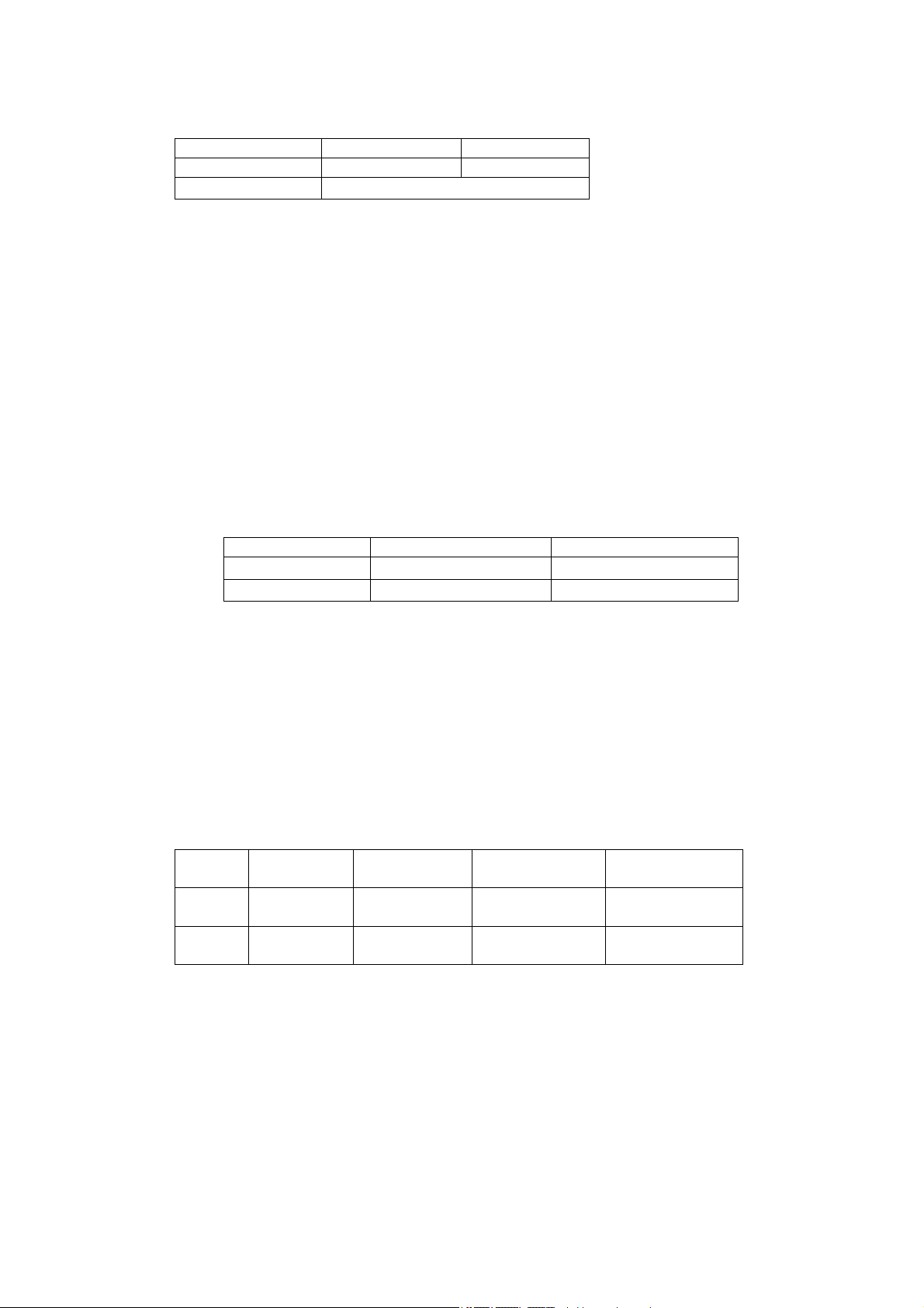
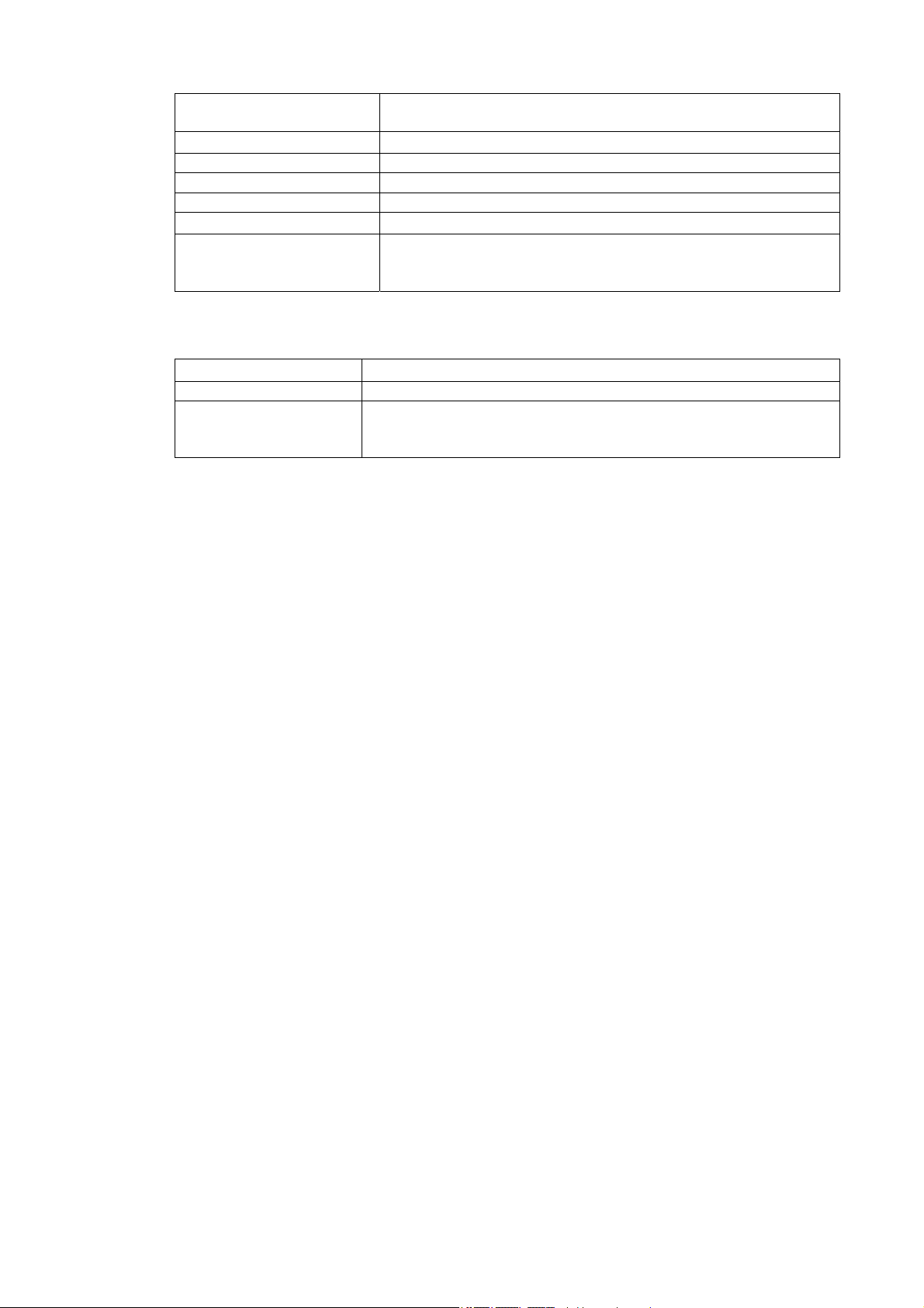
2.4 Specifictions of Cutter
Print Area
※Value of D doesn’t change in case paper wide changes to 75 or 65mm
1) Cutting Method :Slide System
2) Cutting Mode :Full cut/Partial Cut A/Partial Cut B
※Selectable by Command
3) Allowance of Cutting Frequency :30 cuts per minutes
4) Paper Thickness :65~150µm
※In case Partial Cut B is conducted with the paper with 75µm and
5) Note:
・In case you burden palaten like drawing paper strongly after partial cut etc, please pay
・2mm paper feed is automatically effected to avoid paper jam after cutting, the above
Feed Direction
Symbol Descriptions Meaurement
A Tab size on Partial Cutting 1.5±0.5mm
B Position of Printer Head (Cut to Print) 9.5±1mm
C Limit of Backfeed 6.5mm
D From edge of pape (1 dot~) to the
center of tab on partial cutting
attention there is a case that the next line is not properly printed. You should pull left or
right end of paper to avoid burdening palaten or taking measure of feeding the paper by
approx. 1mm before printing.
mentioned cutting margin is 11.5±1mm.
Cutting Postion
Backfeed Limit
Position of Printing Head
D
A
C
B
30±0.5mm(NP-2511)
40±0.5mm(NP-3511)
more thicker, there may be a case that paper is drawn from
mechanism side at the time of extracting paper.
D-F0446 NP-2511/3511 series Specifications Ver.0.07
8
Page 15
2.5 Postion of Black Mark
p
Print surface
Printing Head Position
Feed direction
Sensor ①
Defaut:
Pa
eroutsensor
Sensor ② Sensor ③
Default:
Mark sensor
B
C
D
E
1) Name of Symbol
Symbol Descriptons
A Printer Head~Sensor Position
B Sensor①position
C Sensor②positon
D Sensor③position
E
Paper Width
2) Sensor Positon
A(±1mm) B(±0.5mm) C(±0.5mm) D(±0.5mm) E(-1mm)
2inch
11.5 8.0 30.0 52.0 58
11.5 7.5 40 N.A. 65
3inch
11.5 7.5 40 72.5 76
11.5 7.5 40 72.5 80
3) Sensor Specifications
Sensor①and③ are selectable. Standard is Sensor③.
Mark Sensor and No paper Sensor are selectable by MS2-6.
MS2-6
Standard
Options
OFF Sensor③ Sensor②
ON Sensor② Sensor③
OFF Sensor① Sensor②
ON Sensor② Sensor①
Mark Sensor No Paper Sensor
※Please remove dust and paper powder etc on Sensor periodically.
A
D-F0446 NP-2511/3511 series Specifications Ver.0.07
9
Page 16
4) Black Mark Printing Specifications
Mark Print position *1 The center of Sensor set by Mark Sensor is reference
position.
Mark Width(Min) *1
left and right 7.5mm(Min 15mm)from reference position
Height of Mark (Min) 5mm
Printing Side Not Printing Side
PCS value 0.9
Reflectance Ratio
Preprint limited Area
*1
Reflectance less 7% of 900nm(infra-red)
Preprint with dark color is prohibited on the area on left and
right 7.5mm from reference position. You should fully confirm
to use paper preprinted.
*1:In case you set Mark Sensor on Sensor③ in using paper width 76mm, specifications
is partly changed as per below mentioned.
Mark Print Positon
Paper edge on Sensor③ side is reference position.
Mark Width(Min) 10mm from reference point.
Preprint limited area Preprint with dark color is prohibited on the area on 10mm from
reference point. You should fully confirm to use paper
preprinted.
D-F0446 NP-2511/3511 series Specifications Ver.0.07
10
Page 17
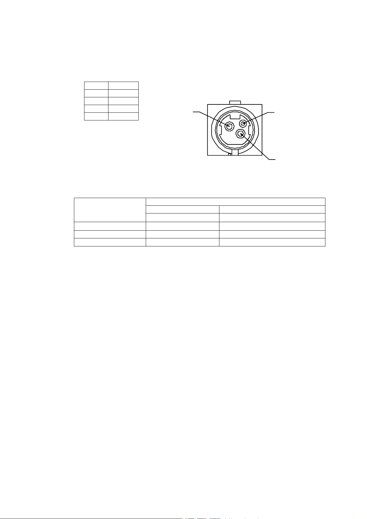
2.6 Power Supply Specifications
1) Power supply input connector
The printer should be connected with the specific AC adaptor.
Connector on printer side: TCS7960-5320177 Hoshiden or equivalent
Connector on Adaptor side: TCP8927-631177 Hoshiden or equivalent
2) Power Supply Voltage:DC24V±5%
3) Current Consumption
Condition:Optimized drive print、dual partitioning print
*1 A power supply with enough capacity is required in order to secure a good printing
*2 If power supply cable is excessively long, the operation may become unstable. Cable
No function
1 +24V
2 GND
3 N.C
shell FG
Connector Fig.
1
3
2
※1※2
Consumption Current
Power supply
Standby
Print avarage 25% Max. approx. 3.5A
Print avarage 100% Max. approx. 14A
quality. Depending on the printing contents, the current may be big at the peak time.
should be made as short as possible. If not available, connect cables near the printer
and place an electrolysis condenser of 2200µ between power supply and ground.
Voltage resistance should be higher than 35V.
2-inch 3-inch
+24V±5% +24V±5%
約 80mA(typ)
D-F0446 NP-2511/3511 series Specifications Ver.0.07
11
Page 18

2.7 Reliability Specifications
1) Head Life
①Thermal Head
Anti-Pulse Characterics :100 million pulse
Anti-abration characteristic :100km
②Cutter Life :1 milions
③Life Definition
・ Entering period abrasion of failure period.
・ Condition to satifiy life is as follows:;
Average Print Ratio:12.5%
Recommended Thermal Paper:PD160R/PD450-145
Print Density :100%
※If paper but recommended paper is used, there will be different life by
the paper of quality, width and thickness. The user must confirm the
abovementioned paper actually.
2) MTBF(Mean Time Between Failfure)
5
2.3×10
hours
D-F0446 NP-2511/3511 series Specifications Ver.0.07
12
Page 19
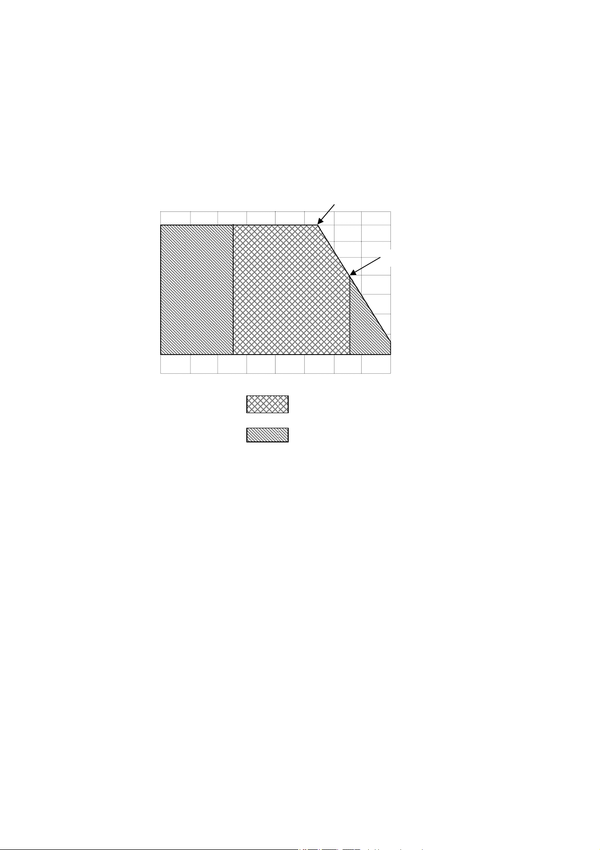
2.8 Environment Specifications
1) Operating Envirnment
Temperature : -20~60℃ *NP-3511Rev「01A」
*in case of NP-3511Rev「no mark」-20~45℃
Humidity: 10~80%RH
Non Codensing, 80%RH supposed 35℃
*Warrant scope of print quality (P/Q) & Print operatable (P/O) scope
85%R
80
35℃ 80%
60
45℃ 50%
40
20
-20
0
20
40
Guarantee of P/Q temp&humid
60℃
Guarantee of P/O temp&humid
2)Archiving environment(except for papers)
Temparature : -30~70℃
Humidity : 10~90%RH
Non Condensing
High-temparature and humidity:40℃ 90%RH(non condesing)is the worst.
3)Safety Regulations
CE mark (Approved)
UL60950-1(Approved)
VCCI : Class A (Approved)
FCC : Class A (Approved)
*The above regulations are adapted to NP3511, but NP2511 in review.
D-F0446 NP-2511/3511 series Specifications Ver.0.07
13
Page 20
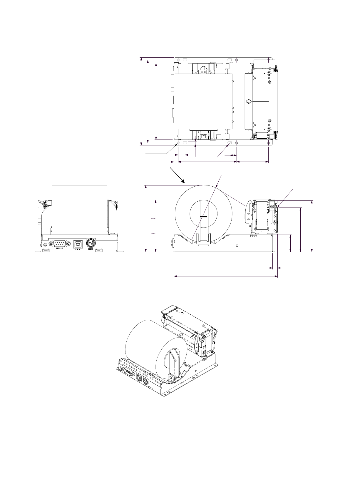
2.9 Dimenssions
1) NP-3511
120
127
111
85
φ
φ
8
6
10
46
3
6- φ 3.5
Paper
10
3.2
6
96.7
75.2
150.4
7.4
* The above is the external drawing of NP-3511 USB/Serial multiple Interface type.
Paper Exit position
用紙排出位置
74.43
64.1
25
D-F0446 NP-2511/3511 series Specifications Ver.0.07
14
Page 21

2) NP-2511
Paper Exit position
46
10
143
6
φ
85
3.2
10
6
6- φ 3.5
75.2
64.1 用紙排出位置
7.4
150.4
φ
3
8
99
ロール紙
Paper
25
106
72.2
91
97.1
* The above is the external drawing of NP-2511 USB/Serial multiple Interface type.
D-F0446 NP-2511/3511 series Specifications Ver.0.07
※本図はシリアル, USBコネクタ併設タイプ (NP-2511)を
図面化したものである。
15
Page 22

3. Configurations
3.1 Interface specifications : RS-232C
1) Synchronization : Asynchronous
2) Transmission speed : 9600, 19200, 38400, 115200bps (user selectable)
3) A word consists of
Start bit : 1bit
Data bit : 7 or 8 bit (user selectable)
Parity bit : odd, even or no parity (user selectable)
Stop bit : more than 1 bit
4) Signal polarity
RS-232C
Mark = Logic “1” (-3V -- -12V)
Space = Logic “0” (+3V -- +12V)
5) Receive data (RXD signal)
Mark = 1
Space = 0
6) Transmit data (TXD signal)
Mark = 1
Space = 0
XON/XOFF when controlled
DC1(11) h code, XON :possible to receive data
DC3(13) h code, XOFF :Impossible to receive data
7) Receive-Control (RTS signal)
Mark : Impossible to receive data
Space: Possible to receive data
8) Transmit-Permission (CTS signal)
Mark: Impossible to transfer data
Space: Possible to transfer data
3.2 Interface specifications: USB (V2.0 Full Speed)
1) Version :V2.0 FULL SPEED (12Mbps)
2) Port :Upstreamport (B jack)
3) Power Supply : Self Powered
4) Reset function : Automatic reset by insert and remove USB cable
D-F0446 NP-2511/3511 series Specifications Ver.0.07
16
Page 23

3.3 Connecter Signal Details
1) CN1: Power Input Connecter
Printer side: TCS7960-5320177(Hoshiden) or equivalent
Adaptor side: TCP8927-531177, TCP8927-631177,
TCP8935-531177(Hoshiden)equivalent (Hoshiden) or Equivalent
Pin No. Signal name Input/Output Function
1 VH Input Power DC +24V
2 GND - Power ground
3 N.C -
Shell FG - FG
*A sufficient volume of power supply is required to maintain print quality due to high peak current
that may run according to printing contents.
*If power supply cable is excessively long, the operation may become unstable. Cable should be
as short as possible. If not available, connect cables near the printer and place an electrolysis
condenser of 2200µ between power supply and ground. Voltage resistance should be higher
than 35V.
2) CN2: Serial Data signal input connector (Multiple Interface type only)
Printer side: JEC-9P (JST) or equivalent
Host side: JEC-9S (JST) or equivalent
Pin No. Signal Input/Output Function Remark
2 RXD Input Serial receiving data
3 TXD Output Serial transmitting data
4 RTS Output Receiving permission signal Connect to No.7
5 GND - Singnal ground
7 RTS Output Receiving permission signal Connect to No. 4
8 CTS Input Transmit permission signal
1, 6, 9 N.C -
3) CN3: USB data signal input connector
Printer side: B jack DUSB-BRA42-T11 (DDK) or equivalent
Host side: B plug or equivalent
Pin No. Signal Input / Output Function Remark
1 VBUS Input Power line Non twist power line
2 D- Input and output Data line Twist pair signal line
3 D+ Input and output Data line Twist pair signal line
4 GND - Power line Non twist power line
Shell Shield -
* Use USB cable which conforms to the standard (V2.0 FULL SPEED)
* We shall not be liable for operation using the connector not comformed with the standard.
D-F0446 NP-2511/3511 series Specifications Ver.0.07
17
Page 24

4) CN7: connecting to presenter (NPT-301)
Printer side: 53047-0810 (Molex) or equivalent
Host side: 51021-0800 (Molex) or equivalent
Pin no Signal Input/Output Function
1
2
3
4
5
6
7
8
LED1+ output To sensorLED1
sensor1 input From sensor1
GND
-
Signal GND
LED2+ output To Sensor LED2
sensor2 input From Sensor2
GND
-
Signal GND
M+ output Motor drive output
M- output Motor drive output
* Please do not connect any presenter except NPT-301.
There may be failure when other presenter connected.
* NPT-305/NP01201/NP01301 in review
D-F0446 NP-2511/3511 series Specifications Ver.0.07
18
Page 25

4. Functions
4.1 Function Setting
4.1.1 Dip Switch
Functions O N OFF
Factory setting
NP-2511
NP-3511
NP-2511U
NP-3511U
DS1-1 OFF OFF
DS1-2 OFF OFF
DS1-3
DS1-4 OFF OFF
DS1-5
Transmit setting See Fig.1
Serial transmit speed See Fig.2
OFF OFF
OFF OFF
DS1-6 Serial flow control XON/XOFF RTS/CTS OFF OFF
DS1-7 Autocutter no yes OFF OFF
DS1-8
Reserved
- -
OFF
OFF
* DS1-8 must be “OFF”
Fig.1 Transmit Setting
Interface Bit length Parity setting DS1-1 DS1-2 DS1-3
USB - - OFF OFF OFF
nil O N OFF OFF
8bit odd OFF O N OFF
Serial
even O N O N OFF
nil OFF OFF O N
7bit odd O N OFF O N
even OFF O N O N
Reserved - - O N O N O N
Fig.2 Serial transmit speed
Serial transmit speed DS1-4 DS1-5
115200 OFF OFF
38400 O N OFF
19200 OFF O N
9600 O N O N
4.1.2 Memory Switch
Function O N OFF
Factory setting
NP-2511
NP-3511
NP-2511U
NP-3511U
MS2-1 Japanese Kanji code Shift JIS JIS OFF OFF
MS2-2 OFF OFF
MS2-3
Built-in Language font
Switch
See Fig.3
OFF OFF
MS2-4 Near empty no yes OFF OFF
MS2-5 Presenter (NPT-301) Yes No OFF OFF
MS2-6 Black mark sensor Center Side OFF OFF
MS2-7 Reserved - - OFF OFF
MS2-8 Reserved - - OFF OFF
* MS2-7 and MS2-8 must be “OFF”.
D-F0446 NP-2511/3511 series Specifications Ver.0.07
19
Page 26

How to set Memory Switch
1. Tharmal head cover is opened and push FEED switch more than 3 seconds. Re-write mode of
Memory Switch is activated. (ALARM red: flash)
2. Lift your finger off FEED switch, set Memory Switch on dip switch.
3. By pushing FEED switch, setting of dip switch is copied to Memory Switch. (ALARM red:light)
Return dip switch setting to original position, and thermal head cover is closed. The contents of
Memory Switch is printed for confirmation.
* Pleas do not forget to return Dip switch setting to original position.
* When you cancel Rewrite mode of Memory Switch, let thermal head cover be closed.
* After setting of Memory Switch, transition to the self print is not available when thermal head
cover is closed.
Fig.3 Installed Language Fonts
Installed language fonts MS2-2 MS2-3
Japanese OFF OFF
Chinese O N OFF
Korean OFF O N
Greek O N O N
* Japanse JIS C 6226 :Full size
Katakana character set+Extended graphic character set +Code Page 858+International
character:Half size
* Korean KS X 1001:1992 :Full size
Katakana character set+Extended graphic character set+Code Page 858 :Half size
(KS X 1001:1992 installed font)
* Chinese GB18030-2000 :Half/Full size
* Greek Code Page1253 :Full size (1 byte code)
Please refer to [select character code table] for other language.
4.1.3 Self Print
1) By performing self-diagnostic print following items are checked.
* Proper function of control circuitry
* Control F/W version
* Status of Dip switch setting and memory switch setting
* Correct function of paper out sensor
2) Start and end of self diagnostic print
Turn on the power while pressing the FEED switch and release the FEED switch after
initializing print mechanism. Self diagnostic print will take place.
The self diagnostic print automatically ends when a preset print pattern are printed.
While printing, the printer is in Off-line mode.
4.1.4 Paper sensor
Paper end sensor equipped in the paper course of the printer mechanism, and it detects
paper end status. It stops printing by error bit ON, when detected the paper end.
The sensor can not detect paper end glued to the core. Please exchange the paper roll
shortly after detecting the paper end.
D-F0446 NP-2511/3511 series Specifications Ver.0.07
20
Page 27

4.2 Processing error
1) Error detection details
Name Status
Status
Info
Alarm
Status
Removal
Comm. Error 232C Comm.error - - Adjust comm.condtion
Parity
Overrun
Framing
Normal Normal - OFF
Print start status Print start setting by bit7 1 OFF Print end setting by
command(not error ) command
Paper near empty Remaining paper detect bit0 1 Blink Paper replenishment
Paper near empty sensor
detect
(MS2-4:OFF)
Paper end No paper bit2 1 ON Paper replenishment
Thermal head cover Thermal head cover open bit1 1 ON Thermal head cover
open close
Head Temparature
Head Tempt. over 70°
C
bit3 1 Blink Automatically recover
at 65°
C
Cuttter error Cutter Paper Jam bit4 1 Blink Open head cover,.
Not connected remove error factor,
Paper detect error Paper not detected during bit5 1 Blink close head cover
presenter operation or Mark
detection.
Presenter clamp Presenter clamps paper bit6 1 Blink Extract paper
When the above errors are detected (except transmission error and paper near empty , print
start status ), printer stops all operation.
・It turns ON error bit of the status information.
2) Return to normal status from error statuses
Remove causes of error statuses and turn the power on again or push the RESET switch
to return to normal. When this process is activated, at the time of power switch turned off,
the printer will be initialized, so that settings are required again.
If data remains in the buffer, attention should be paid
4.3 Buffer full print
If there remains data after one line of data is received, printer automatically prints preceding
data. The volume of buffer full data varies depending on ANK, Kanji or bit images.
D-F0446 NP-2511/3511 series Specifications Ver.0.07
21
Page 28

4.4. Drive Select
Select optimization, fixed division (no division / dual partitioning) by command.
Select depending on provided power and print duty.
1) Select Partition Drive
Please refer command table.
* Prinint speed is decreased when select dual partitioning.
2) Optimization
Select no division or dual partitioning according to the number of total dot of print per
line.
No division Dual partitioning
3-inch model 352dotl or less 353dot or more
* When select optimization, printing speed changed depending on printing ratio, and
printing noise occurred somewhat.
* When select optimization, printing quality is descended somewhat.
4.5 Select Full size and half size character
Character How to select
Japanese Command[FS &],[FS .] or Switching Shift JIS code
Korean
Command[FS &]、[FS .]
Please refer to the followings
Chinese
1 byte code (Half size) 2 byte code (Full size)
st
byte
1
nd
2
byte
rd
byte
3
th
byte
4
00 h ~ 80 h 81 h ~ FE h 81 h ~ FE h
40 h ~ 7E h
80 h ~ FE h
4 byte code (Full
size)
30 h ~ 39 h
81 h ~ FE h
30 h ~ 39 h
Greek No switch (Only Full size)
Polish No switch (Only half size)
Russian No switch (Only half size)
Scandinavian No switch (Only half size)
Turkish No switch (Only half size)
D-F0446 NP-2511/3511 series Specifications Ver.0.07
22
Page 29

4.6 Operation panel
The printer is ready for the following operations;
1) ALARM (red) [alarm lamp]
Will turn on (or blink) when printer is on error status.
Will blink/ turn on/ turn off when rewriting Flash Rom
※The pattern of the ALARM indication is in the following chart.
Display pattern Printer status
1
0
1
0
1
0
1
0
0.1secc
0.1sec
0.2secc
0.2sec
1
0
1
0
0.2sec
0.2sec 1.0sec
2.2sec
2.2sec
Normal Status
Print(receive) ready
No paper
Thermal head cover open
F/W write mode 9
Paper near empty 2
Head temperature over 70℃
Or, Wrong head connection
Auto cutter error 6
Paper detect error 7
Presenter clamp
( detects remaining paper)
Priority
(9:High ~ 1:Low)
1
3
4
5
8
2) FEED Switch [Paper feed switch]
Switch to feed paper in the forward direction
Also, used in self-printing .
3) Reset SW
Reset SW is placed on the right side of FEED SW, and you cannot push Reset SW
with your finger to avoid misoperation. (Push Reset SW lightly with ballpoint pen etc,
and release.)
By activating Reset SW, the printer is initialized at the time of power on.
* Reset Switch will be implemented on production February 2007.
D-F0446 NP-2511/3511 series Specifications Ver.0.07
23
Page 30

4.7 How to set roll paper
1) NP-3511
- As illustrated, you lift the shaft vertically and set a roll paper passing through the shaft
(Pay attention to the direction of roll paper.)
- Set shaft back to previous position.
- Put the edge of paper into loading slot. (Put it straight into slot, not curl)
- Retract the paper automatically with sensor detected. (In case of power on)
- Paper is retracted into a certain length and can print after cut the excess of it.
(Attention): The leading edge of paper should be straight and at right angle.
Paper at cutout state might be retracted at an angle.
Roll paper
Print side
Winding direc.
Paper Support Shaft
Guide for paper
D-F0446 NP-2511/3511 series Specifications Ver.0.07
24
Page 31

2) NP-2511
D-F0446 NP-2511/3511 series Specifications Ver.0.07
25
Page 32

4.8 How to remove the jammed paper
- Pull up head open lever at the direction as illustrated.
- Remove all jammed paper on the route of paper.
- Close thermal head cover completely.(Until hearing click)
Attentions: Since the thermal head reaches a high temperature, please don’t touch it. If a
paper jam occurr, a cutter blade may stick out. DO NOT TOUCH IT.
Head Open Lever
* This is drawing of NP3511
4.9 How to clean Thermal Head
In case the heat generation part of the thermal head gets wisps of paper, the quality of print
may drop. In this case, you should clean the thermal head as following procedures.
1) Thermal Head
Remove wips of paper and grim with swab moistened alcohols solvent (ethanol / IPA) on
the heat generation part of thermal head. The use of methanol in alcohols solvent is
prohibited.
2) Platen
Remove wips of paper and dust on the surface by wiping like rubbing slightly with dry cloth.
3) Mark Sensor/No paper sensor and its surrounding
Remove wips and paper and dust on sensors with swab moistened slightly.
4) Attentions
・Since the thermal head reach a high temperature shorly after printing, don’t touch it with
hands.
・Don’t touch the heat generation part of thermal head with hands and metal materials.
・When you clean thermal head, you should pay fully attention to the risk of breaking of
thermal head due to static electricity.
・In case a lot of wips of paper are genrated depending on paper, timing of maintenaunce
should be decided after confirming the paper.
・You should power on after completely driy on the printer.
D-F0446 NP-2511/3511 series Specifications Ver.0.07
26
Page 33

5. Command
5.1 Command Table
1) 【Horizental Tab】《HT》································································································29
2) 【Line feed】《LF》 ········································································································29
3) 【Carriage return】《CR》 ······························································································29
4) 【Software Reset】《DC1》····························································································29
5) 【Barcode termination change】《ESC RS c n》 ···························································29
6) 【Setting character right space quantity】《ESC SP n》 ················································29
7) 【Print mode batch setting】《ESC ! n》 ········································································30
8) 【Absolute position setting】《ESC $ n1 n2》 ································································30
9) ■【Download characters set set/reset】《ESC % n》 ···················································30
10) ■【Defintion of Download Characters】《ESC & s n m a Dn》 ·····································31
11) 【Bit Image mode Set】《ESC * m n1 n2 Dn》 ······························································33
12) 【Underline Set/Reset】《ESC - n》···············································································35
13) 【1/6
inch line feed pitch】《ESC 2》··············································································35
14) 【Sets smallest pitch line feed】《ESC 3 n》··································································35
15) 【Data input control】《ESC = n》··················································································35
16) 【Printer initialization】《ESC @》 ·················································································35
17) 【Back feed】《ESC B n》····························································································36
18) 【Horizental tab position set】《ESC D n1 n2 --- NUL》·················································36
19) 【Bold print set/reset】《ESC E n》················································································36
20) 【Double strike print set/reset】《ESC G n》 ·································································36
21) 【Print and smallest pitch line feed】《ESC J n》···························································37
22) ■【International character select】《ESC R n》····························································37
23) 【90° clockwise rotated character set and reset】《ESC V n》 ······································37
24) 【Relative position set】《ESC ¥ n1 n2》·······································································37
25) 【Position alignment】《ESC a n》·················································································38
26) 【Raster Bit Image】《ESC b n1 n2 n3 Dn》··································································39
27) 【FEED Switch enable/disable】《ESC c 5 n》 ······························································40
28) 【Print and “n” line feed】《ESC d n》············································································40
29) 【Presenter ejection mode set】《ESC h n》 ·································································40
30) 【Full Cut】《ESC i》······································································································40
31) 【Partial Cut A】《ESC m》 ····························································································40
32) 【Partial Cut B】《ESC n》·····························································································40
33) 【Compulsary Feed】《ESC r n》 ··················································································41
34) 【Printer information transitting】《ESC s n》 ································································41
35) ▲【Select Character code table】《ESC t n》 ·······························································41
36) 【Printer status transmit】《ESC v》 ··············································································41
37) 【Inverted Character Set・Reset】《ESC { n》······························································42
38) 【Select division drive】《GS % n》 ···············································································42
39) 【Black and white reverse print set and reset】《GS B n》 ············································42
40) 【Print start/Print finish setting】《GS G n》·································································43
41) 【Selection of printing position of HRI character】《GS H n》········································43
42) 【NV Bit Image Print】《GS P n》 ··················································································44
43) 【NV Bit Image registration】《GS T n》 ········································································44
44) 【Firmfare downloading】《GS d Dn》 ···········································································44
45) 【Select font of HRI character】《GS f n》 ·····································································44
46) 【Setting of the height of barcode】《GS h n》 ······························································45
D-F0446 NP-2511/3511 series Specifications Ver.0.07
27
Page 34

47) 【Barcode Print】《GS k n Dn NUL》·············································································45
48) 【Auto-Transmitting of Printer Status】《GS v NUL》·····················································45
49) 【Select horizontal size of Barcode】《GS w n》 ···························································45
50) 【Print density set】《GS ~ n》 ······················································································46
51) 【Cue Operation】《Gs FF n》 ·······················································································46
52) 【mark detection method & position correction feed quantity set】《Gs ( m a n1 n2》···46
53) 【cue process set at setting paper】《Gs m n 》 ···························································46
54) 【Printable area set】《Gs W n1 n2》 ············································································47
55) 【maximum printing speed set】《GS S n》 ···································································47
56) 【butch set of Japanese Kanji print mode】《FS ! n》····················································47
57) ▲【Japanese Kainji mode set】《FS &》·······································································47
58) 【Japanese Kanji underline set/reset】《FS - n》···························································48
59) ▲【Reset Japanese Kanji mode】《FS .》 ····································································48
60) ■【Definition of additional Characters】《FS 2 a1 a2 Dn》···········································49
61) ■【Select Japanese Kanji code】《FS C n》 ································································50
62) 【Japanese Kanji Space setting】《FS S n1 n2》 ··························································50
63) 【Select character table code】《FS T n》 ·····································································51
64) 【Set/Reset Quadruple Japanese Kanji character】《FS W n》·····································51
▲ is effected on Japanese/Korean font selected from language font.
■ is effected on Japanese font selected.
※51)~53 is related to Black Mark Commands.
※17)、51)~55) is valid for Firm Ware Ver.1.10 afterwards in NP-3511
※In case print method is storage, print speed will be max. 200mm /sec.
D-F0446 NP-2511/3511 series Specifications Ver.0.07
28
Page 35

5.2 Printer Driver
Please apply the driver stated below for using under Windows environment.
Windows 2000/Windows XP/Windows CE 5.0/Linux(only sample)
5.3 Command details
1) 【Horizental Tab】《HT》
Code:〔09〕h
Print position is moved at next horizental tab.
* Horizental tab is set by【Horizental tab position set】command.
th
* Default of【Horizental tab】is every 8
character(9 digit,17 digit,・・,41digit)in font A.
* If the next【Horizental tab】is not set, this command is disregarded.
2) 【Line feed】《LF》
Code:〔0A〕h
Data in print line buffer is printed, and linefeed is conducted based on preset line feed
quantity.
3) 【Carriage return】《CR》
Code:〔0D〕h
* This command is disregarded.
4) 【Software Reset】《DC1》
Code:〔11 〕h
Let Farmware restarted as same procedures when power-on
* Since this command stored on internal reception input buffer executes sequential, the
timing of receptin of command is different from that of command execution.
* Software reset is activated after auto-cutter finished driving.
5) 【Barcode termination change】《ESC RS c n》
Code:〔1B〕h+〔1E〕h+〔63〕+n ※〔n=00,80〕h
Change terminator of 【Barcode print】command with n.
* n is indicated as follows;
n(hex) termination
00
80
〔00〕h
〔FF〕h
* Default of n is〔00〕h
6) 【Setting character right space quantity】《ESC SP n》
Code:〔1B〕h+〔20〕h+n ※〔00≤n≤20〕h
Set the value of right space of character by dot (by 1/203 inch)
* Right space is reflected with zoom when double width zoom mode
* Default of n is〔00〕h.
D-F0446 NP-2511/3511 series Specifications Ver.0.07
29
Page 36

7) 【Print mode batch setting】《ESC ! n》
Code:〔1B〕h+〔21〕h+n ※〔00≤n≤FF〕h
Print mode setting
* n has the following meanings.
bit funciton
value
0 1
0 Character font Font A Font B
1 Undifined
2 Undifined
3 Bold reset set
4 Double height reset set
5 Double width reset set
6 Undifined
7 Underline reset set
* If double height and double width are set at the same time, quadruple character will be
formed.
* All of the printed characters will be underlined except for the 90° rotated characters and
spaces created by horizontal tab.
* Underline width is determined by the value set in [Underline set/reset] section.
The default value is 1 dot width.
* Bold print control is effected when Kanji mode
* Different sizes of character mixed such as double width and normal size can be
printed.
* The default of n is〔00〕h.
8) 【Absolute position setting】《ESC $ n1 n2》
Code:〔1B〕h+〔24〕h+n1+n2 ※〔00≤n1≤FF〕h
※〔00≤n2≤02〕h
Setting from the front on position of start of print by the number of dot
(by 1/203-inch position)
* 256 into the number of dot at print start point is n2、remainder is n1
* print start point is n1+n2×256 from the front of the line.
* Disregard the setting when beyond the end of the line.
* When this command is received on the middle of line, it is efective not to over the
current position.
9) ■【Download characters set set/reset】《ESC % n》
※Effective only when Japanese is selected.
Code:〔1B〕h+〔25〕h+n ※〔00≤n≤FF〕h
Set/Reset Download characters
* n is the bottom bit. Effective on only(b0). b0 mentioned as follows;
b0 Function
0 Reset Download character set
1 Set Downlaod character set
* Default of n is 〔00〕h
D-F0446 NP-2511/3511 series Specifications Ver.0.07
30
Page 37

10) ■【Defintion of Download Characters】《ESC & s n m a Dn》
※Efective only when selected Japanese.
Code:〔1B〕h+〔26〕h+s+n+m+a+Dn ※〔s=03〕h
※〔20≤ n≤ 7E〕h,〔20≤ m≤ 7E〕h
※ Font A〔01≤a≤0C〕h
※ Font B〔01≤a≤09〕h
Definition of font of Download characters on alphanumeric characters.
* “s” indicates a number of bytes in a vertical direction and “a” is a number of dots in
horizontal direction.
* “n” indicates the start character code, and “m” means the end character code. If only 1
character should be defined, then n = m.
* Definable characters are from (20)h to (7E)h on ASCII code. (95 characters)
* Dn indicates data to be defined, It indicates the“a” dot pattern from the left.
Remaining area on the right of character is filled with space.
* Once a download character defined by command, it remains valid until execution
of (Software Reset) and Reset Switch or the power is turned off.
* Redefined character is only effective to specified area.
<Reference>
In the case of Font A
12dots
P1
P4
P7 P34
MSB
24dots
P2
P5
P35
P3
P6
P36
LSB
P1=〔00〕h,P4=〔00〕h,P7=〔00〕h,P10=〔00〕h,…
P2=〔00〕h,P5=〔00〕h,P8=〔0F〕h,P11=〔72〕h,…
P3=〔08〕h,P6=〔F8〕h,P9=〔08〕h,P12=〔00〕h,…
D-F0446 NP-2511/3511 series Specifications Ver.0.07
31
Page 38

<Refernce>
In the case of Font B
9dots
MSB
P1
P4
P7 P25
17dots
P2
P5
P26
LSB
MSB
P27 P6 P3
LSB
P1=〔40〕h,P4=〔7F〕h,P7=〔41〕h,P10=〔41〕h,…
P2=〔04〕h,P5=〔FC〕h,P8=〔04〕h,P11=〔04〕h,…
P3=〔00〕h,P6=〔00〕h,P9=〔00〕h,P12=〔00〕h,…
D-F0446 NP-2511/3511 series Specifications Ver.0.07
32
Page 39

11) 【Bit Image mode Set】《ESC * m n1 n2 Dn》
Code:〔1B〕h+〔2A〕h+m+n1+n2+Dn ※〔m=indicated below〕h
※〔00≤n1≤FF〕h
※〔00≤n2≤02〕h
* Data is printed in bit image mode for resolution specified by “m”.
* Total print dots are divided by 256, quotient is n2 and remainder is n1.
* Total print dots in bit image mode is n1+(256×n2).
* If the bit image input data exceeds specified position, the exceeded data will be
disregarded.
* Bit image data (Dn) interprets bit 1 as print and bit 0 as not print.
* Bit image mode is indicated below;
<Standard>
Vertical direction Horizental direction
m(hex) Bit image mode
00
01
20
21,23
8 dot
single density
8 dot
double density
24 dot
single density
24 dot]
double density
Dot quantity
Dot
density
Dot
density
8 67DPI 101DPI 288
8 67DPI 203DPI 576
24 203DPI 101DPI 288
24 203DPI 203DPI 576
Maximum dot number
3-inch
model
D-F0446 NP-2511/3511 series Specifications Ver.0.07
33
Page 40

<Relationship between Bit Image data and Printed dot>
・8 dot bit image
MSB
D1 D2 D3
D1 D2 D3
LSB
Print data
=1dot
Single density Double density
・24 dot image bit
D1 D4 D7 MSB
D1 D2 D3 D7 D8 D9
D4
D5 D6
D2
D5
D8
D3
D6 D9
LSB
Print data
=1dot
Single density Double density
D-F0446 NP-2511/3511 series Specifications Ver.0.07
34
Page 41

12) 【Underline Set/Reset】《ESC - n》
Code:〔1B〕h+〔2D〕h+n ※〔00≤n≤02〕h
Sets and Resets Underline
* Underline is valid for all characters except for the area skipped by horizontal tab. Also
Underline is not valid for 90° rotated character.
* This command is not valid when Kanji mode.
* Underline is verified with n value as shown bellow.
n(hex) Type of underlines
00 Reset underline
01 Set one dot underline
02 Set two dot underline
* Default value of n is 〔00〕h.
13) 【1/6
inch line feed pitch】《ESC 2》
Code:〔1B〕h+〔32〕h
Sets one line feed to 1/6th of an inch.
14) 【Sets smallest pitch line feed】《ESC 3 n》
Code:〔1B〕h+〔33〕h+n ※〔00≤n≤FF〕h
Sets a line feed pitch to n/203rd of an inch.
* Despite of height set by value, the same space with character height is sent by line
feed.
* Default value of n is 〔22〕h.
15) 【Data input control】《ESC = n》
Code:〔1B〕h+〔3D〕h+n ※〔00≤n≤FF〕h
Select apparatus to be data input from host
* Each bit of N indicates below;
bit function
value
0 1
0 Printer invalid valid
1 Undefined
2 Undefined
3 Undefined
4 Undefined
5 Undefined
6 Undefined
7 Undefined
* When printer is not selected、all receiption data is disregarded until this printer is
selected by this command.
* When printer is not selected, busy situation may remains by operation of printer.
* Default value of n is〔01〕h.
16) 【Printer initialization】《ESC @》
Code:〔1B〕h+〔40〕h
Clears the data stored in the print buffer and resets each setting to default values.
* It does not clear the data stored in the internal receive buffer.
* re-reads the dip switch and memory switch.
* It is stored in the internal receive buffer and activated in sequential.
D-F0446 NP-2511/3511 series Specifications Ver.0.07
35
Page 42

17) 【Back feed】《ESC B n》
Code:〔1B〕h+〔42〕h+n ※〔00≤n≤FF〕h
This command is for forwarding paper in reverse direction.
* Set forwarding length in n Dot line. In case of set〔00〕h, no forwarding.
* You should set this command once only due to avoid paper jam, and then forward
paper in right direction.
* Backlash may let paper not put properly.
* In case there is print data on buffer of Print Line buffer, it should be backfeed after
prining.
* Tip of paper should not be exceed the limited of backfeed.
(Use〔n≤34〕h)
18) 【Horizental tab position set】《ESC D n1 n2 --- NUL》
Code:〔1B〕h+〔44〕h+n1+n2+---+〔00〕h ※〔00≤n≤FF〕h
Sets horizental tab position.
* “n” indicates the digits number from the head to the tab position. In this case, [n = tab
position – 1].
* Tab position is set at the location of character width x n from the beginning of a line.
The character width in this case includes character right space. When double width
function is set, then the width becomes double of ordinary character.
* Maximum number of tab positions is 32. If setting exceeds 32, then
the exceeded values are neglected.
* < ESC D NUL > clears all tab positions being set. After the tab is cleared,
(horizontal tab) will be ignored.
th
* Default value is set at every 8 characters of font A (at 9
, 17th, 25th, 33rd and 41st digit).
19) 【Bold print set/reset】《ESC E n》
Code:〔1B〕h+〔45〕h+n ※〔00≤n≤FF〕h
Set and Reset Bold Print
* “n” is only valid for LSB (b0)
* LSB (b0) is defined as following.
b0 Value
0 Resets Bold print
1 Sets Bold print
* When bold print, the result of print may be deformed.
* Default value of n is〔00〕h.
20) 【Double strike print set/reset】《ESC G n》
Code:〔1B〕h+〔47〕h+n ※〔00≤n≤FF〕h
Set and Reset Double Strike Print Function.
* “n” is only valid for LSB (b0)
Control by LSB (b0) is explained as following.
b0 Descriptions
0 Reset Double Strike print
1 Set Double Strike print
* When Double Strike print, the result of print may be deformed.
* Default value of n is 〔00〕h.
D-F0446 NP-2511/3511 series Specifications Ver.0.07
36
Page 43

21) 【Print and smallest pitch line feed】《ESC J n》
Code:〔1B〕h+〔4A〕h+n ※〔00≤n≤FF〕h
Prints the data in the print line buffer and feeds the paper by n/203rd of an inch.
* Line feed quantity does not remain.
* Beginning of a line is a print start position.
* The height of character for a line is always sent by line feed. If the value of height is set
by “n” below the height of character, the same space with character height is sent by
line feed.
22) ■【International character select】《ESC R n》
Effective only when selecting either overseas or domestic code in [character code
table select] and Japanese in language font.
Code:〔1B〕h+〔52〕h+n ※〔00≤n≤0A〕h
Selects International characters
* The values of “n” have following meanings
n(hex) Character set
00 U.S.A.
01 France
02 Germany
03 U.K.
04 Denmark I
05 Sweden
06 Italy
07 Spain
08 Japan
09 Norway
0A Denmark II
* Default value of n is〔08〕h.
23) 【90° clockwise rotated character set and reset】《ESC V n》
Code:〔1B〕h+〔56〕h+n ※〔00≤n≤01〕h
Sets and resets 90° clockwise rotated character.
* (Underline set) is invalid when the 90° clockwise rotated character set.
* “n” has the following meaning.
n(hex) Descriptions
00
01
Reset 90° rotated character
Set 90° rotated character
* Default value of n is〔00〕h.
24) 【Relative position set】《ESC ¥ n1 n2》
Code:〔1B〕h+〔5C〕h+n1+n2 ※〔00≤n1≤FF〕h
※〔00≤n2≤FF〕h
Print start position is assigned by dots in 1/203rd of inch from the current postion.
* Divide the value of dot by 256, place quotient to n2, and remainder to n1.
* Rightward defines plus, leftward defines minus.
* When n dot is set on rightward, the value is n1 + n2 x 256.
* When n dot is set on leftward, the value is set by n’s complement.
n dot = 65536-n
* Setting which exceeds end of line is ignored.
D-F0446 NP-2511/3511 series Specifications Ver.0.07
37
Page 44

25) 【Position alignment】《ESC a n》
Code:〔1B〕h+〔61〕h+n ※〔00≤n≤02〕h
Align print data in a line at the specfied position.
(Except for definite Bit Image)
* n has the following meanings;
n(hex) Position
00 Left alignment
01 Centering
02 Right alignment
* Effective only when input on the beginning of the line.
* Default value ofnis〔00〕h
D-F0446 NP-2511/3511 series Specifications Ver.0.07
38
Page 45

26) 【Raster Bit Image】《ESC b n1 n2 n3 Dn》
Code:〔1B〕h+〔62〕h+n1+n2+n3+Dn
※〔01≤n1≤48〕h:3-inch model
※〔00≤n2≤FF〕h
※〔00≤n3≤FF〕h
Print data in raster bit image.
* Dn is raster bit image data.
* The printer prints raster bit image of width n1 byte by height n2+(256*n3) dot lines.
* The total byte of the requested raster bit image data (Dn) is n1*(n2+(256*n3)).
* Raster bit image data (Dn) exceeding the printing field will be disregarded.
* Raster bit image data (Dn) interprets bit”1” as print and bit”0” as not print.
* Relation between raster bit image data (Dn) and printed dots are as follows.
n1 byte
D1 D2 Dn1
Dn1+1 Dn1+2 Dn1*2
Dn1*2+1 Dn1*2+2 Dn1*3
n2+(256*n3)dots
n1*(n2+(256*n3))
MSB LSB
* Please add < ESC J 00h > ([1B] h + [4A] h + [00] h) at the end of this command.
* Data of this command is started printing after storage regardless of <start print/end of
set>.
D-F0446 NP-2511/3511 series Specifications Ver.0.07
39
Page 46

27) 【FEED Switch enable/disable】《ESC c 5 n》
Code:〔1B〕h+〔63〕h+〔35〕h+n ※〔00≤n≤FF〕h
Changes the FEED switch valid or invalid
* “n” is only valid for LSB (b0)
* “n” bit has a following meanings
B0 Description
0 Enable FEED switch
1 Disable FEED switch
* Default value of “n” is [00] h.
28) 【Print and “n” line feed】《ESC d n》
Code:〔1B〕h+〔64〕h+n ※〔00≤n≤FF〕h
Prints the data in the print line buffer and feeds paper by “n” lines.
* The setting value by this command will not remain, so please set the value every time
you use this command.
* Beginning of a line is a next print start position.
* If there is print data remained, line feed should be always activated for th same height
of character.
29) 【Presenter ejection mode set】《ESC h n》
※This command is effective only when you use Presenter(NPT-301)
Code:〔1B〕h+〔68〕h+n ※〔00≤n≤01〕h
Select “Clamp Feed” or “All Feed” on Presenter Feed mode
*n has a following meanings.
n(hex) Function
00 Clamp Feed
01 All Feed
* Default of n is〔00〕h.
30) 【Full Cut】《ESC i》
Code:〔1B〕h+〔69〕h
* Full cut the paper is activated.
* Effective at the head of a line
31) 【Partial Cut A】《ESC m》
Code:〔1B〕h+〔6D〕h
* conduct partial cut (center is left uncut.)
* Effective at the head of a line
32) 【Partial Cut B】《ESC n》
Code:〔1B〕h+〔6E〕h
* conduct partial cut (a few mm in the center is left uncut.)
* Effective at the head of a line.
* The part of Uncut is thicker than one on (Partial Cut A).
D-F0446 NP-2511/3511 series Specifications Ver.0.07
40
Page 47

33) 【Compulsary Feed】《ESC r n》
※This command is effective only when you use Presenter(NPT-301)
Code:〔1B〕h+〔72〕h+n ※〔00≤n≤01〕h
(Compulsary Feed) is used for compulsary feed / (All Feed) with status of unremoval of
paper in a certain time running after (Clamp Feed).
* This command let motor normal or reverse rotate the motor until feed all paper.
* n has the following meanings.
n(hex) Motor
00 Forward Rotation
01 Reverse Rotation
34) 【Printer information transitting】《ESC s n》
Code:〔1B〕h+〔73〕h+n
Conduct printer information transmitting.
* Details of n and return information mentioned as the following;
n(hex)
02 Model info.
03
04
05
Category of Printer
Information
Return Data format Return data length
Variable length string
(terminal NULL=00h)
F/W version info. Fixed length string
Boot version info. Fixed length string
SW setting info. Fix Length Hex data
Max32Byte
8Byte
8Byte
4Byte
Return Transimit Format
〔FF〕h + n(※1) +return data
※1 n is designated by command.
35) ▲【Select Character code table】《ESC t n》
※Effective only when Japanese and Korean selected
Code:〔1B〕h+〔74〕h+n ※〔00≤n≤06〕h
Conduct selection of Character code table
* n has the following meaning.
n(hex) Font Table
00 International Code page
01 Japanese Code page
02 Code Page 858
03 Code Page 1250
04 Code Page 1251
05 Code Page 1252
06 Code Page 1254
* Default value of n is〔01〕h
36) 【Printer status transmit】《ESC v》
Code:〔1B〕h+〔76〕h
Transmit current printer status
* Status transmit is one byte. Please refer to the error detection for the details.
* Transmit one byte after confirmation of receivable on host (CTS singnalon space status)
* When host is unreceivable (CTS singnal at Mark status), printer is waiting until host is
receivable.
* This command is effective only for Serial Interface.
* Command should be issued before transmit of print data.
(Stored on internal receipt input buffer, run on sequential)
* Receivable except for internal receive input buffer is full.
D-F0446 NP-2511/3511 series Specifications Ver.0.07
41
Page 48

37) 【Inverted Character Set・Reset】《ESC { n》
Code:〔1B〕h+〔7B〕h+n ※〔00≤n≤FF〕h
Set or Reset Inverted Character function.
* n is only valid for LSB (b0)
*LSB(b0) has the following meaning.
b0 Descriptions
0 Resets inverted character
1 Sets interted character
* The command is only valid when it is assigned at the beginning of a line.
* Default Value of n is〔00〕h.
38) 【Select division drive】《GS % n》
Code:〔1D〕h+〔25〕h+n ※〔01≤n≤03〕h
Select division drive
* n has the following meaning;
n(hex) divisions
01 Fix without divisions
02 Fix in two division
03 Optimization
・Default value of n is〔03〕h.
・Not divide out of area
39) 【Black and white reverse print set and reset】《GS B n》
Code:〔1D〕h+〔42〕+n ※〔00≤n≤FF〕h
Sets and resets black and white reverse print.
* n is only valid for LSB(b0).
* LSB(b0) has the following meanings;
b0 Functions
0 Reset black and white reverse print
1 Set Black and White reverse print
* The built-in characters and the downloaded can be reverse printed.
* The right side space of character set by [Set right space of a character] is also
included for reverse print. However, it does not cover the skipped space made by bit
image, download bit image, NV bit image, barcode, HRI characters, horizontal tab,
specify absolute position, specify relative position.
* It does not include the space between the lines.
* Reverse print has a priority over “underline specified”. If a character is reversed, the
character is not underlined. However, the underline setting remains effective.
* If “highlight” or “double strike” is set on the reverse print, the print may result in
damages.
* The default value of “n” is [00] h.
D-F0446 NP-2511/3511 series Specifications Ver.0.07
42
Page 49

40) 【Print start/Print finish setting】《GS G n》
Code:〔1D〕h+〔47〕h+n
Operate on printer status bit 7(print start/end set status).
* By using this command before and after printing data, the printer will monitor the
printer status bit 7 and will be able to detect the printer status whether it is now printing,
or finished printing.
* n has the following meaning;
n(hex) Function
21 Priner status bit 7 "1"(print start setting)
20 Printer status bit 7 "0"(print finish setting)
31
Printer status bit 7 "1"(print start setting) nomination
+ job ID(4Byte)
30 Printer status bit 7 "0"(print finish setting) , will transmit”Print
finished” message of the following format.※designated under
jobID(4Byte):n=11h.
〔FF〕h+〔13〕h+jobID(4Byte)+finished status(1Byte)
+backup(3Byte)
* The method of printing is storage type.
* Once the receiving data storaged on memory, it starts printing data storaged after
receipt of “print finish setting”.
* A little bit time-lag remains between “Reception start”and“Print start”but Printing is
stable at the highest speed. In case over printing capacity of 160mm on printing length,
Memory storages every 160mm on printing length and prints.
Therefore, the squences is repeated, on the edge between storage and printing
remains pause and start printing.
* When the data between “Print start” and “Finishing setting” happen an error on the way
of printing, you should disregard it until “Finish setting”.
* When this command repeatedly is used on USB interface, you should use n=〔31〕
h,〔30〕h only and certainly transmit next print start command after reception of finish
status.
41) 【Selection of printing position of HRI character】《GS H n》
Code:〔1D〕h+〔48〕h+n ※〔00≤n≤03〕h
You should select printing position of HRI character when printing Barcode.
* n has the following meaning.
n(hex) Printing position
00 No printing
01 Above barcode
02 Under barcode
03 Above & Under barcode
・HRI character is printed by font selected with【Font selection of HRI character】.
・The default of n is [00]h.
D-F0446 NP-2511/3511 series Specifications Ver.0.07
43
Page 50

42) 【NV Bit Image Print】《GS P n》
Code:〔1D〕h+〔50〕h+n ※〔00≤n≤02〕h,〔10≤n≤12〕h
Print the print data registered bit image.
* Selects one of the print pattern among three registered patterns by assigning 0 to 2
value to “n”.
* with making n to 1, ([10]h ~ [12] h), if vertical direction size of fixed bit image to be
printed is larger than that of distance between print head ~ cutter, full cut is inserted
automatically when the distance between print head ~ cutter is pinted, the remainder
is continuously printed after full cut. By using this function, it will be possible to print
larger top logo than that of distance between print head ~ cutter and no margin at the
top of page.
* n has the following meaning.
n(hex) Print pattern Cut insertion
00 Pattern 0
01 Pattern 1
nill
02 Pattern 2
10~12 00~02
available
43) 【NV Bit Image registration】《GS T n》
Code:〔1D〕h+〔54〕h+n
Register the predetermined bit image print data.
* It is possible to register from 0 to 2 different kinds of patterns (3 patterns).
* In each pattern, up to the maximum of 11cm length of bit image print data can be
registered. The bit image print data exceeding the maximum length is neglected.
* The registered data is not erased even if the power is set on/off or [the printer is
initialized], [software reset]
* n has the following meaning.
n(hex) Function
0 Start of pattern 0 registration
1 Start of pattern 1 registration
2 Start of pattern 2 registration
FF End of registration
* When registrations started in the middle of a line, whole line is registered.
* When registration ended in the middle of a line, whole line is not registered.
* Following is a command sequence of pattern 0 registration.
GS T 00 h + (bit image data assigned by ESC *) x n lines + GS T FF h
44) 【Firmfare downloading】《GS d Dn》
Code:〔1D〕h+〔64〕h+Dn
* Download printer firmware in hexadecimal code and rewrite firmware
according to the outcome, and reboot.
* Dn is firmware’s hex code which complies with INTELLEX Hex format.
45) 【Select font of HRI character】《GS f n》
Code:〔1D〕h+〔66〕h+n ※〔00≤n≤01〕h
* Selects Font of HRI character when print barcode.
* n has the following meaning.
n(hex) Font style
00 Font A
01 Font B
* The default of n is〔00〕h.
D-F0446 NP-2511/3511 series Specifications Ver.0.07
44
Page 51

46) 【Setting of the height of barcode】《GS h n》
Code:〔1D〕h+〔68〕h+n ※〔01≤n≤FF〕h
Sets the height of barcode by dot.
* n is indicated dot for horizental direction.
* The default of n is 〔A2〕h.(162dots)
47) 【Barcode Print】《GS k n Dn NUL》
コード:〔1D〕h+〔6B〕h+n+Dn+〔00〕h ※〔00≤n≤07〕h
Selects barcode symbology and prints barcode.
* The next print start position is set at the beginning of the line.
* Select following barcode symbology with “n” value.
n(hex) Barcode Symbology
00 UPC-A
01 UPC-E
02 JAN-13(EAN-13)
03 JAN-8(EAN-8)
04 CODE39
05 ITF
06 CODABAR(NW-7)
07 CODE128
* Dn indicates the character code to be printed.
* If character code Dn is not a printable character, following data after Dn will be treated
as normal print data.
* When the barcode symbology whose print character number is fixed is selected, the
character numbers should match to the print character numbers.
* If horizontal data exceed one line, the exceeded data cannot be printed.
* [00] h at the end of this command can be changed to [FF] h by [barcode end change]
48) 【Auto-Transmitting of Printer Status】《GS v NUL》
Code:〔1D〕h+〔76〕h+〔00〕h
When Print Status is changed, Auto-Transmitting is activated.
* Print Status is 1 byte and the contents as per details of error detection.
* Once the setting is done, it is effective until executing 【software reset】,reset switch
or power-off.
* This command is stored on internal reception input buffer, run by sequential.
49) 【Select horizontal size of Barcode】《GS w n》
Code:〔1D〕h+〔77〕h+n ※〔02≤n≤04〕h
Select horizontal size of Barcode.
* Default of n is〔03〕h.
D-F0446 NP-2511/3511 series Specifications Ver.0.07
45
Page 52

50) 【Print density set】《GS ~ n》
Code:〔1D〕h+〔7E〕h+n ※〔41≤n≤87〕h
Set Print density in the range from 65% to 135%.
* Though n ranges〔41〕h(65%)~〔87〕h(135%),
set it for actual use in the range〔41〕h(65%)~〔82〕h(130%).
* Default of n is〔64〕h.
* When this command is used while 【Print set/Finish set】command, the setting is
disregarded.
51) 【Cue Operation】《Gs FF n》
Code: [1D] h + [0C] h + n ※〔00, 10≤n≤11〕h
After detecting black mark, activate feed for preset alignment correction.
* n has following meaning.
n(hex) Description
00 Mark detection + feed to print start position
10 Mark detection + feed to cut position + full cut
11 Mark detection + feed to cut position + partial cut A
52) 【mark detection method & position correction feed quantity set】《Gs ( m a n1 n2》
※ [01≤m,a≤01] h
Code: [1D] h + [28] h + m + a + n1 + n2 ※ [01≤n1,n2≤FF] h
Set mark detection method and feed quantity of position correction.
* m, a, n1, n2 has following meaning.
00
01
Set item
m(hex)
Feed quantity
to print start
position
Feed quantity
to cut position
Detecting method
a(hex)
00 Upper edge
01 Lower edge
00 Upper edge
01 Lower edge
Setting value
(n2*256+n1)
Set a position from mark detection to print
start by dot.
Set a position from mark detection to cut
by dot.
* feed quantity is set by dot with signed 16bit(-32767~32767), upper Bit is set by n2,
lower Bit by n1.
* When feed quantity is set negatively, paper edge does not exeed back feed limit
(Please refer to cutter specification).
* Defaut is as follows:
Item Detecting mentod Preset value
Print start position Upper edge 92 dot ( 11.5mm: between sensor ~ head
Cutting position Uppder edge 168dot ( 21mm: between sensor~cutter )
53) 【cue process set at setting paper】《Gs m n 》
Code: [1D] h + [6D] h +n ※ [00≤n≤FF] h
Activate cue process set at setting a paper.
* each bit of n has a following meaning.
Bit Function
value
0 1
0 Cue operation after auto loading Invalidation valid
1 Cue operation after thermal head cover open/close Invalidation Valid
2 Cue operation after Feed switch push Invalidation valid
* this cue operation is same as selecting Gs FF [10] h
* default of n is [00] h
D-F0446 NP-2511/3511 series Specifications Ver.0.07
46
Page 53

54) 【Printable area set】《Gs W n1 n2》
Code : [1D] h + [57] h + n1 + n2 ※ [03≤n1≤50] h
Set left margin and printable area ※ [03≤n2≤4D] h
* n1 = left margin (mm)
* n2 = printable area(mm)
* right marging(mm) = 80 – (left margin + printable area )
* please refer to [printable area] for the details.
55) 【maximum printing speed set】《GS S n》
Code: [1D] h + [53] h + n ※ [00≤n≤04] h
Set maximum printing speed at storage print.
* “n” has following meaning
n(hex) Maximum printing speed
00 Max. 200mm/sec
01 Max. 150mm/sec
n(hex) Maximum printing speed
03 Max. 100mm/sec
04 Max. 75mm/sec
02 Max. 125mm/sec
* Default of n is [00] h
56) 【butch set of Japanese Kanji print mode】《FS ! n》
Code:〔1C〕h+〔21〕h+n ※〔00≤n≤FF〕h
Set Japanese Kanji overall print mode set.
* “n” has the following meaning.
Bit Function
Value
0 1
0 undefined
1 undefined
2 Double width Reset Set
3 Double height Reset Set
4 Undefined
5 Undefined
6 Undefined
7 Underline Reset Set
* If double height and double width are set at the same time ,quadruple character will
be formed.
* All of the printed characters will be underlined except for the 90° clockwise rotated
characters and spaces created by horizontal tab.
* Underline width is determined by the value set in 【Kanji Underline set/reset]】.
The default value is “1”.
* Different sizes of character mixed such as normal size, double height, double width
and quadruple can be printed.
* Combined print with ANK Character is available.
* Default of n is〔00〕h.
57) ▲【Japanese Kainji mode set】《FS &》
* Effective only when Japanese font and Korean font selected.
Code:〔1C〕h+〔26〕h
Set Japanese Kanji mode
* It is not effective when selected Shift JIS of Japanese Kanji.
* Default is the reset of Japanese Kanji mode.
D-F0446 NP-2511/3511 series Specifications Ver.0.07
47
Page 54

58) 【Japanese Kanji underline set/reset】《FS - n》
Code:〔1C〕h+〔2D〕h+n ※〔00≤n≤02〕h
Set/reset underline of Japanese Kanji
* All of the printed characters will be underlined except for the 90° clockwise rotated
characters and spaces created by horizontal tab.
* This command is not effective when reset Japanese Kanji mode.
* “n” has the following meanings.
n(hex) Function
00 Reset underline of Japanese Kanji
01 Set 1 dot underline of Japanese Kanji
02 Set 2 dot underline of Japanese Kanji
* Default of n is〔00〕h.
59) ▲【Reset Japanese Kanji mode】《FS .》
※Effective only when Japanse font , Korean font selected.
Code:〔1C〕h+〔2E〕h
Reset Japanese Kanji mode
* It is not effective when selected Shift JIS of Japanese Kanji.
* Default is the reset of Japanese Kanji mode.
D-F0446 NP-2511/3511 series Specifications Ver.0.07
48
Page 55

60) ■【Definition of additional Characters】《FS 2 a1 a2 Dn》
※ Effecive only when the Japanese font is selected.
Code:〔1C〕h+〔32〕h+a1+a2+Dn
JIS code ※〔a1=77〕h
※〔21≤a2≤7E〕h
Shift JIS code ※〔a1=EC〕h
※〔40≤a2≤7E, 80≤a2≤9E〕h
Definition of Additional Kanji Character
* Definition of up to 94 characters available.
* Dn is the data to be defined. Data will be 3 byte (vertical) x 24 dot(horizontal) =72
byte.
* The default status is "space".
* Once defined by this command, it will be effective until execution of 【Software reset】
and reset switch or power off.
* Only specified area will be redefined.
<Example>
24dots
MSB
P1 P4 P7
P70
24dots P2 P5
P71
P3 P6 P72 LSB
D-F0446 NP-2511/3511 series Specifications Ver.0.07
49
Page 56

P1=〔02〕h,P4=〔01〕h,P7=〔81〕h,P10=〔40〕h,P13=〔70〕h,P16=〔30〕h,…
P2=〔00〕h,P5=〔00〕h,P8=〔C0〕h,P11=〔C3〕h,P14=〔0F〕h,P17=〔38〕h,…
P3=〔40〕h,P6=〔60〕h,P9=〔FE〕h,P12=〔FF〕h,P15=〔03〕h,P18=〔00〕h,…
61) ■【Select Japanese Kanji code】《FS C n》
* Effecive only when the Japanese font is selected
Code:〔1C〕h+〔43〕h+n ※〔00≤n≤01〕h
Select Japanese Kanji code.
* “n” has the following meaning.
n(hex) Code
00 JIS code
01 Shift JIS code
* Default is set with memory switch MS2-1
62) 【Japanese Kanji Space setting】《FS S n1 n2》
Code:〔1C〕h+〔53〕h+n1+n2 ※〔00≤n1≤20〕h
※〔00≤n2≤20〕h
Set side space of Japanese Kanji by dot unit
* n1 sets the left space. Default value is [00] h.
* n2 sets the right space. Default value is [00] h.
* Width of space will be double when selected double width.
D-F0446 NP-2511/3511 series Specifications Ver.0.07
50
Page 57

63) 【Select character table code】《FS T n》
Code:〔1C〕h+〔54〕h+n ※〔00≤n≤03〕h
Switch character table code
* “n” has the following.
n(hex) Built-in Character code table
00 Japanese
01 Chinese
02 Korean
03 Greek
* Default of n is set by memory switch(MS2-2、MS2-3)
* By executing 【printer initialization】, this setting will be returned to value set by
memory switch (MS2-2, MS2-3).
64) 【Set/Reset Quadruple Japanese Kanji character】《FS W n》
Code:〔1C〕h+〔57〕h+n ※〔00≤n≤FF〕h
Set/reset Quadruple Japanese Kanji character
* “n” is only effective on LSB bit(b0).
* Indicated control by LSB bit(b0) as follows;
b0 Function
0 Reset Quadruple
1 Set Quadruple
* Default of n is〔00〕h
D-F0446 NP-2511/3511 series Specifications Ver.0.07
51
Page 58

6. Character code table
6.1 Domestic Character code table(International character set:Japanese)
HEX 0 1 2 3 4 5 6 7 8 9 A B C D E F
HEX BIN
0
1
2
3
4
5
6
7
8
9
A
B
C
D
E
F
* “SP” indicated Space
* “CR” is ignored.
* Printer operation cannot be guaranteed if the blank control code (codes below [1F] h) is
transmitted to printer.
* This code table indicates simplified symbol and is not print result. There may be some difference
from the actual print.
0000 0001 0010 0011 0100 0101 0110 0111 1000 1001 1010 1011 1100 1101 1110 1111
0000
NUL SP 0 @ P ` p
0001
0010
0011
0100
0101
0110
0111
1000
1001
1010
1011
1100
1101
1110
1111
DC1 ! 1 A Q a q
” 2 B R b r
DC3 # 3 C S c s
$ 4 D T d t
% 5 E U e u
& 6 F V f v
’ 7 G W g w
( 8 H X h x
HT ) 9 I Y i y
LF * : J Z j z
ESC + ; K [ k {
FF FS , < L ¥ l
CR GS - = M ] m }
RS . > N ^ n ~
/ ? O _ o SP +
SP ー タ ミ
。 ア チ ム
「 イ ツ メ
」 ウ テ モ
、 エ ト ヤ
・ オ ナ ユ
ヲ カ ニ ヨ
ァ キ ヌ ラ
ィ ク ネ リ
ゥ ケ ノ ル
ェ コ ハ レ
ォ サ ヒ ロ
ャ シ フ ワ ● 村
ュ ス ヘ ン ○ 人
ョ セ ホ ゛ /
ッ ソ マ ゜ \ SP
×
円
年
月
日
時
分
秒
〒
市
区
町
D-F0446 NP-2511/3511 series Specifications Ver.0.07
52
Page 59

6.2 Overseas character code(International set: USA)
HEX 0 1 2 3 4 5 6 7 8 9 A B C D E F
HEX BIN
0
1
2
3
4
5
6
7
8
9
A
B
C
D
E
F
* “SP” indicated Space
* “CR” is ignored.
* Printer operation cannot be guaranteed if the blank control code (codes below [1F] h) is
transmitted to printer.
* This code table indicates simplified symbol and is not print result. There may be some difference
from the actual print.
0000 0001 0010 0011 0100 0101 0110 0111 1000 1001 1010 1011 1100 1101 1110 1111
0000
NUL SP 0 @ P ` p
0001
0010
0011
0100
0101
0110
0111
1000
1001
1010
1011
1100
1101
1110
1111
DC1 ! 1 A Q a q
” 2 B R b r
DC3 # 3 C S c s
$ 4 D T d t
% 5 E U e u
& 6 F V f v
’ 7 G W g w
( 8 H X h x
HT ) 9 I Y i y
LF * : J Z j z
ESC + ; K [ k {
FF FS , < L \ l
CR GS - = M ] m }
RS . > N ^ n ~
/ ? O _ o SP
¥
α ≡
β ±
Γ
π
Σ
σ
μ ÷
τ
θ
Ω
δ √
∞
φ
∈
∩ SP
D-F0446 NP-2511/3511 series Specifications Ver.0.07
53
Page 60

6.3 CODE PAGE858
HEX 0 1 2 3 4 5 6 7 8 9 A B C D E F
HEX BIN
0
1
2
3
4
5
6
7
8
9
A
B
C
D
E
F
* “SP” indicated Space
* “CR” is ignored.
* Printer operation cannot be guaranteed if the blank control code (codes below [1F] h) is
transmitted to printer.
* This code table indicates simplified symbol and is not print result. There may be some difference
from the actual print.
6.4 International character code table
n Character set 23h 24h 40h 5Bh 5Ch 5Dh 5Eh 60h 7Bh 7Ch 7Dh 7Eh
U.S.A.
00h
France
01h
Germany
02h
U.K.
03h
Denmark I
04h
Sweden
05h
Italy
06h
Spain
07h
Japan
08h
Norway
09h
Denmark II
0Ah
* This code table indicates simplified symbol and is not print result. There may be some difference
from the actual print.
0000 0001 0010 0011 0100 0101 0110 0111 1000 1001 1010 1011 1100 1101 1110 1111
0000
NUL SP 0 @ P ` p
0001
0010
0011
0100
0101
0110
0111
1000
1001
1010
1011
1100
1101
1110
1111
DC1 ! 1 A Q a q
” 2 B R b r
DC3 # 3 C S c s
$ 4 D T d t
% 5 E U e u
& 6 F V f v
’ 7 G W g w
( 8 H X h x
HT ) 9 I Y i y
LF * : J Z j z
ESC + ; K [ k {
FF FS , < L \ l
CR GS - = M ] m }
RS . > N ^ n ~
/ ? O _ o SP
# $ @ [ \ ] ^
# $
# $ §
$ @ [ \ ] ^ { }
# $ @
#
# $ @
$ @
# $ @ [ ¥ ] ^
#
# $
\ ^
○C
○R
φ
×
¥
{ }
§ ^
^
^
^
{ }
}
-
β ±
=
¶
§
μ ÷
1
3
2
SP
β
D-F0446 NP-2511/3511 series Specifications Ver.0.07
54
Page 61

6.5 CODE PAGE1250
* This code table indicates simplified symbol and is not print result. There may be some difference
from the actual print.
D-F0446 NP-2511/3511 series Specifications Ver.0.07
55
Page 62

6.6 CODE PAGE1251
* This code table indicates simplified symbol and is not print result. There may be some difference
from the actual print.
D-F0446 NP-2511/3511 series Specifications Ver.0.07
56
Page 63

6.7 CODE PAGE1252
* This code table indicates simplified symbol and is not print result. There may be some difference
from the actual print.
D-F0446 NP-2511/3511 series Specifications Ver.0.07
57
Page 64

6.8 CODE PAGE1253
* This code table indicates simplified symbol and is not print result. There may be some difference
from the actual print.
D-F0446 NP-2511/3511 series Specifications Ver.0.07
58
Page 65

6.9 CODE PAGE1254
* This code table indicates simplified symbol and is not print result. There may be some difference
from the actual print.
D-F0446 NP-2511/3511 series Specifications Ver.0.07
59
 Loading...