

Page 1
MSI9750A
RF Remote Weight Indicator
Operator’s Manual
Page 2

HANDHELD RF REMOTE INDICATOR for CELLSCALE
®
This Page Intentionally Left Blank
Page 2 MSI-9750A RF Remote Indicator • User Guide
Page 3

MEASUREMENT SYSTEMS INTERNATIONAL
Firmware Version 5-XX for 2450 Modems
TABLE OF CONTENTS
SECTION 1 – INTRODUCTION & ORIENTATION
................................
Introduction
.........................................................................
9750A Keyboard
.................................................................
4
Key Descriptions
.................................................................
5
9750A Display Symbols
......................................................
6
General Information
............................................................
7
Manual & 9750A Conventions
...........................................
7
Features
...............................................................................
8
9750A Block Diagram
........................................................
8
The CellScale Family
..........................................................
9
Unit Setup
.........................................................................
0
Battery
...............................................................................
0
Replacing the Battery
........................................................
0
Charger Adapter
................................................................
0
Charging the Battery
.........................................................
0
SECTION 2 – RF SCALE COMMUNICATIONS
..................................
FCC Statemen
t
..................................................................
Network Description
.........................................................
Antenna
.............................................................................
RF Network Setup
.............................................................
Advanced Modem Settings
...............................................
3
Confi guring for multiple networks
....................................
4
Troubleshooting RF Connection Problems
.......................
5
RF Site Testing
..................................................................
6
CellScale Network Auto Scan
...........................................
6
SECTION 3 – SCALE OPERATION
.................................................
7
Power
...............................................................................
7
Multiple Scale Channels
...................................................
7
Selecting The Active Channel
...........................................
7
To Select The Display Channel
.........................................
8
Zero
...................................................................................
9
Tare
....................................................................................
2
0
Setup Tare Menu
...............................................................
2
Net / Gross
........................................................................
2
Units
..................................................................................
2
2
Peak Hold (Function Key Option)
....................................
Send / Print
........................................................................
Display Test
.......................................................................
ulti-Channel Systems
.....................................................
8
SECTION 4 – FUNCTION KEYS
....................................................
3
Setup Function Keys
.........................................................
3
Default Function Keys
......................................................
2
4
Custom Function Key Labels
............................................
2
6
SECTION 5 – ID CODES
..............................................................
2
7
ID Code Organization
.......................................................
2
7
Setup ID Codes Menu
.......................................................
2
8
Using ID Codes
.................................................................
9
ID Code String 1 & String 2
.............................................
3
0
SECTION 6 – TOTAL / STATISTICS
................................................
3
Total
...................................................................................
3
Auto Total
..........................................................................
3
Setup Total Menu
..............................................................
3
View Total
.........................................................................
3
3
Statistics
...........................................................................
3
4
SECTION 7 – 9750A SETUP
.......................................................
3
6
System Setup Menu
..........................................................
3
6
Password Locks
.................................................................
3
7
Keyboard Lock
..................................................................
3
8
Display Setup
....................................................................
3
8
Display Setup Menu
..........................................................
0
Scale Display Setup Menu – Preset Displays
...................
Using Display Setup
..........................................................
Custom Display Setup
.......................................................
4
3
Custom Screen Setup Procedure
.......................................
4
6
Custom Single Channel Display Setup Menu
...................
4
7
Custom Multi-channel Display Setup Menu
.....................
4
8
SECTION 8 – SET POINTS
...........................................................
4
9
Introduction
.......................................................................
9
Set Point Setup Menu
........................................................
5
0
Program Set Point Menu
...................................................
5
9750A Response Menu
.....................................................
5
Set Point Formula Menu
...................................................
5
3
Direct Relay Control
.........................................................
5
3
SECTION 9 – COMMUNICATION PORTS
.........................................
5
4
Introduction
.......................................................................
5
4
Electrical Conformance
.....................................................
5
4
Mating Cable
.....................................................................
5
4
Data Confi guration
............................................................
5
Trigger Print
......................................................................
5
Comm Port Setup Menu
....................................................
5
5
General Text Entry
............................................................
5
7
General Text Entry Menu
..................................................
5
8
Printer / Output Formatting
...............................................
5
9
Example Printer Formatting
..............................................
5
9
Programming the End of Line or Start of Line StringS
....
6
0
Editing the Print String
.....................................................
6
0
General Text / Control Character Entry
...........................
6
0
Serial Output “@” Commands
..........................................
6
SECTION 10 – DATA LOGGING
...................................................
6
Introduction
.......................................................................
6
Data Logging Setup
..........................................................
6
Data Logging Control Menu
.............................................
6
5
SECTION 11 – TEXT MESSAGING
................................................
6
6
Host Message Design
........................................................
6
6
9750A to Host Messages
...................................................
6
7
SECTION 12 – BAR CODE
..........................................................
6
9
Bar Code Setup Menu
.......................................................
6
9
SECTION 13 – CHANNEL SETUP & CALIBRATION
.........................
7
Channel Setup Menu
.........................................................
7
Calibrate General Information
..........................................
7
Enable Calibration
.............................................................
7
To Calibrate
......................................................................
7
To Enable / Disable AZM (Auto Zero Maintenance)
........
7
Motion Band
.....................................................................
7
4
Center-of-Zero (COZ) Indicator
.......................................
7
5
Reset All
............................................................................
7
5
Installing Firmware Updates
.............................................
7
6
9750A Setup Duplicating
..................................................
7
8
APPENDIX A – MENU MAPS
......................................................
7
9
Setup Select Menu
............................................................
7
9
Total Settings
.....................................................................
7
9
Password Locks
.................................................................
7
9
Function Keys
...................................................................
8
0
Serial & Strings
.................................................................
8
Product ID Codes
..............................................................
8
2
Bar Code Setup
.................................................................
8
2
Tare Settings
......................................................................
8
3
RF Modem Settings
..........................................................
8
3
Scale Display Setup
..........................................................
8
Scale Single Channel Custom Display Setup
...................
8
5
Scale Multi-Channel Custom Display Setup
....................
8
6
Channel / Calibrate Settings
.............................................
8
7
System Settings
.................................................................
8
8
Display Test
.......................................................................
8
8
Monitor Batteries
..............................................................
8
8
Calibration
.........................................................................
8
9
Reset All or Reset RF Modem
..........................................
8
9
General Text Entry
............................................................
9
0
Set Points
...........................................................................
9
APPENDIX B – ASCII CHART
....................................................
9
APPENDIX C – SPECIFICATIONS & SUMMARY OF FEATURES
..........
9
3
THE MSI LIMITED WARRANTY
..................................................
9
MSI CellScale® System • 9750A User Guide Page 3
Page 4
SECTION 1 – INTRODUCTION & ORIENTATION
INTRODUCTION
The Measurement Systems International MSI-9750A RF Remote Indicator is an accessory component of MSI's
CellScale
®
System. Combined with 1 or more CellScales, the 9750A provides complete control over all scale and
data functions. The 9750A serves as a remote terminal for any CellScale and has no internal measurement capa-
bility. One 9750A can read the output of many CellScales, and 1 CellScale can also provide data to many 9750's.
The backlit, alphanumeric graphic display provides precise, unambiguous indication of operating modes such as
Net, Gross, or Total. The 9750A can calibrate a CellScale remotely and provides a user interface to the advanced
features of the CellScale. The CellScale system is digitally calibrated from either the 3750CS Indicator, a 9750A
Indicator, or with a terminal program hooked directly to the CellScale model 9000. The 9750A combined with a
CellScale is designed to meet or exceed the requirements of all regulatory agencies.
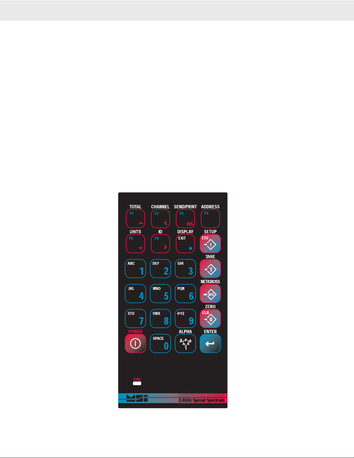
9750A KEYBOARD
PRE SS ENTER
TWICE TO VIEW
FUNCTION KEY
ASSI GNMENT S
HANDHELD RF REMOTE INDICATOR for CELLSCALE
®
Page 4 MSI-9750A RF Remote Indicator • User Guide
Page 5
MEASUREMENT SYSTEMS INTERNATIONAL
Firmware Version 5-XX for 2450 Modems
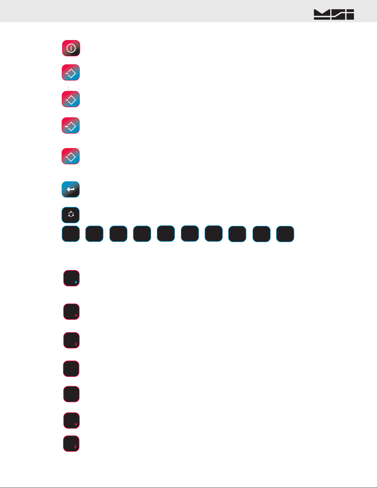
The
key turns the 9750A On and Off. The
key must be held for 1 second to ensure startup.
The
key is used to zero out residual weight on the scale. When entering numbers or strings the
key is used
to Clear (delete) characters.
The
key is used to zero out the weight of containers, trucks, or carriers and to place the scale in the Net weight
mode.
The
key allows the operator to alternate the weight display from Net (Tared) weight to Gross weight. In
some Legal-for-trade jurisdictions, the Gross weight display is limited to 3 seconds.
The
key allows entry into the setup submenus. Use this to fi nd menus for setting the Date and Time, setting up
the function keys, controlling the display mode and backlight, password locks, calibration, etc.. The key is also used for
ape. Use
to return to the previous menu, or display mode.
The
key fi nalizes the entry of numeric or alphanumeric text entries. It also provides an alternate way to maneu-
ver through menus combined with the cursor keys. Pressing
before certain keys takes you directly into various
modes. Pressing
before a Function key enacts the alternate Function key mode.
The
key is used during text entries to select upper case, lower case or numbers. Sometimes used for negative.
The numeric keypad provides all numerals and letters for data entry. Submenus provide punctuation and control charac-
ters.
The
key is used to alternate between single channel displays and multiple channel displays. While in the
multiple channel display, highlight the desired channel using the numeric keys, then press DISPLAY to bring up the
large display. This selected channel is the “Active” channel to which all subsequent actions will be applied. Provides
the decimal point or period in numeric and text entries. Functions as EXIT in menus returning directly to weight display
without having to back through all previous menus.
F1 defaults to
. Pressing this key will cause the current weighment to be added to the total register. In Auto-Total
modes, the
key turns Auto-total off and on. Up Cursor in menus.
F2 defaults to
. When the CellScale has more than 1 channel defi ned in its Scan List, the
key
will select the next active channel in the list. Precede the
key with a numeric entry (1-32) to switch directly
to a channel scan list position. Press
for a shortcut to the “Channel Setup Menu”. Left Cursor in
menus.
F3 defaults to
. The action of this key is dictated by the Function key menu, but is usually used to send
data to the CellScale or one of its hosts. Used for Insert in text and number entry screens.
F4 defaults to
. The
key is used to log on to other CellScale Networks. Pressing the
key alone will change the active network to the next defi ned Network. Preceding the
key with a Network
number (0-31) will cause the 9750A to log directly on the entered Network, if it exists and is active.
F5 defaults to
. Pressing this key will change the operational units (if enabled) of the current focus channel.
F6 defaults to
. Pressing
will change you to the next defi ned ID. Right Cursor in menus.
POWER
ZERO
CLR
0
T
ARE
T
NET/GROSS
B/G
ESC
!
SETUP
ENTER
ALPHA
A
a
1
1
ABC
F1
TOTAL
F2
CHANNEL
F4
ADDRESS
DISPLAY
EXIT
IN
F3
SEND/PRINT
UNITS
F5
ID
F6
9
@YZ
8
VWX7STU
6
PQR5MNO4JKL
3
GHI
2
DEF
0
SPACE
POWER
ZERO
TARE
NET/GROSS
SETUP
ESC
ENTER
ALPHA
POWER
ZERO
ESC
ENTER
ENTER
DISPLAY
TOTAL
TOTAL
CHANNEL
SEND/PRINT
ADDRESS
UNITS
ID
ADDRESS
ID
CHANNEL
CHANNEL
SETUP CHANNEL
ADDRESS
ADDRESS
MSI CellScale® System • 9750A User Guide Page 5
Page 6
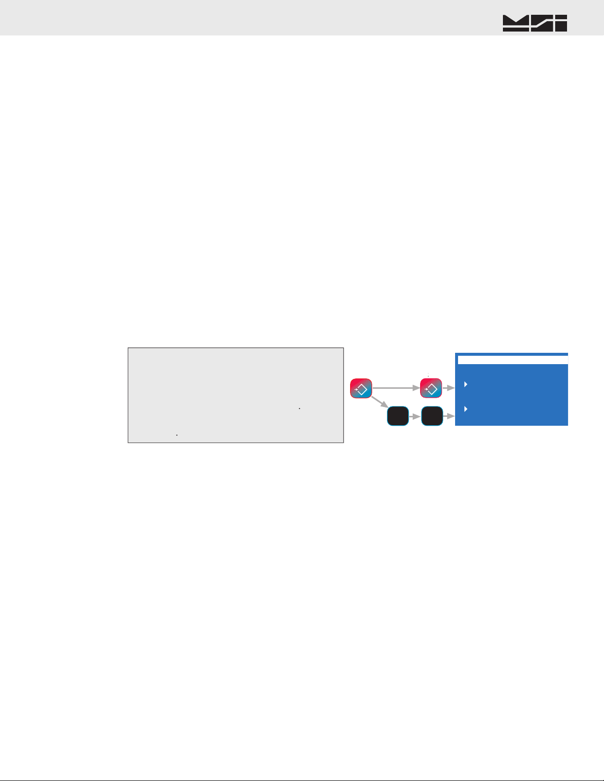
9750A DISPLAY SYMBOLS
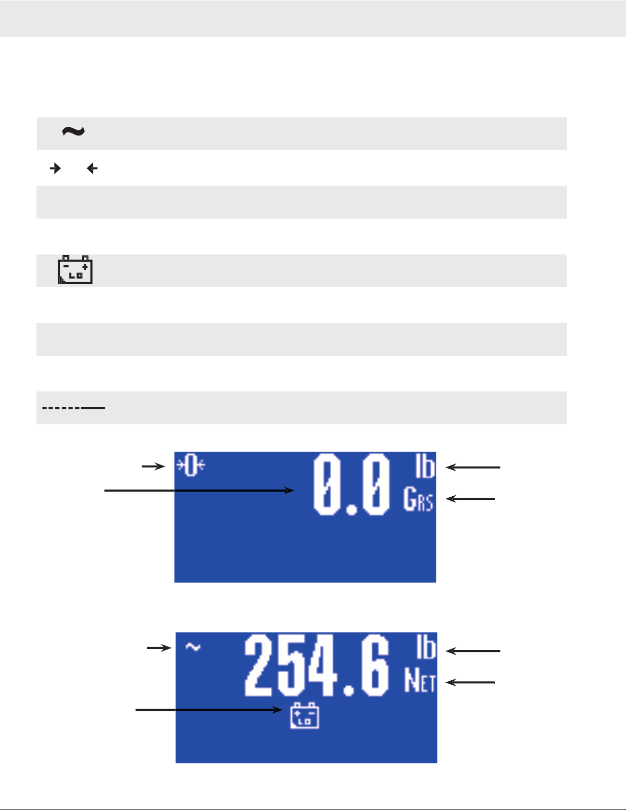
The 9750A uses a full dot matrix graphics display which allows 3 sizes of fonts and full use of graphic symbols.
On standard single channel and multi-channel displays, certain symbols are used for scale specifi c indications.
The motion symbol indicates that the weight has not settled within the motion window (usually ±1d). While this
symbol is illuminated, the scale will not zero, tare, or totalize.
Center-of-Zero – Indicates the weight is within 1/4d of zero. In the small font it appears as “
”.
The Sigma symbol is used to indicate a total weight
GRS – Abbreviation for Gross Weight
Low Battery Symbol – Appears when approximately 10% of battery life remains. The 9750A places the indicator
in various locations depending on the display mode
ton– Indicates US short tons equal to 2000 lb.
tne – Indicates metric tons equal to 1000 kg.
daN – Indicates the force measurement unit dekaNewtons.
Dashes indicate data not yet received from the CellScale, or the RF network is disconnected.
∑
G
RS
ton
tne
daN
Center of Zero Indicator
Weight Display
Scale in Motion Indicator
Low Battery Indicator
Units Indicator
Weight Mode
(Gross, Net, Tare)
Units Indicator
Weight Mode
(Gross, Net, Tare)
Typical weight displays showing the use of common symbols
HANDHELD RF REMOTE INDICATOR for CELLSCALE
®
Page 6 MSI-9750A RF Remote Indicator • User Guide
Page 7

MEASUREMENT SYSTEMS INTERNATIONAL
Firmware Version 5-XX for 2450 Modems
GENERAL INFORMATION
The 9750A is a versatile indicator capable of displaying many data items. As a member of the CellScale family
the 9750A does not stand alone. It is a slave device to a MSI-9000 CellScale. All data displayed on the 9750A is
received via RF from a master CellScale. Many menus in the 9750A depend on information from the CellScale.
Therefore, turn the CellScale on before using the 9750A.
Due to the high data rates in the CellScale system menus usually respond instantly. However there are times
when the CellScale is busy and it will not “service” the 9750A instantly in all circumstances. At these times you
may see the word “Pending” or dashes, or data placeholders which will indicate the CellScale has not yet sent
the required information. Weight displays have priority and are sent before all text strings are updated (such as
channel name, ID name, etc.).
The majority of CellScale installations have only a single scale input. In this case the Multiple Display modes
are not needed. However, even with only a single scale input, Math Channels are available which can be applied
for specialized applications.
1) Keys used in operations are printed in
and capitalized. Numeric keys are bracketed (e.g.
).
2) Setup procedures are usually shown with the shortcut method of reaching the menu. All menus can also be
reached through the “Setup Select Menu”. Use the
key to see all available menu choices.
3) Screen shots are shown for example. Many screens provide additional information to orient the user to the
scale channel, or ID, or selections made. For example, the Function Key Setup menu will show you the current
selection for each key. When you change the function, the previous menu changes to refl ect your choice.
4) If a function key does not work, it is probably because the CellScale is not setup to support the key. For
example, if only one channel is defi ned in the CellScale, pressing the
key will have no effect.
This also applies to the
key. If only one Network has been defi ned, the
key has no
other Network to log onto.
5) Menu Titles are shown at the top of the LCD screen and are fully capitalized.
6) When space permits, selected parameters are shown at the right side fully capitalized.
7) Submenus with multiple choices use a highlighted arrow “
” to indicate current choice(s).
8) When in menus, the
key (same as
) drops back one menu level.
9) When in Setup Menus, the
key returns you directly to the Weight Display (Exit mode).
10) Cursor Keys (alternate functions of F1, F2, F5 and F6) only function in menus. Use the DOWN (
) cursor
key to enable the cursors then use the UP (
) or DOWN (
) cursor to select line items. Use,
, LEFT
(<), or RIGHT (
) cursor keys to rotate through menu choices or select the associated submenu.
11) If a submenu is associated with a menu choice, either highlight the menu choice with the cursor keys and
press
, or press the numbered key corresponding to the desired menu item.
12) If a menu applies to any channel, pressing the
key will select the next channel in the CellScale’s
scan list.
13) If a menu applies to any ID, pressing the
key will select the next ID in the CellScale’s ID list.
14) To input, for example, an ‘E’, fi rst use the
key to change to alpha mode, then press
twice. If you
need two ‘E’s, pause briefl y until the display cursor has moved to the next position, then press
twice.
15) In single display modes, pressing the
key highlights the whole display to indicate the next press of
a Function key will use the alternate mode (Enter-Function Key).
ENTER
ESC
>
ADDRESS
DISPLAY
BLUE
SETUP
^
[7]
CHANNEL
[5]
CHANNEL
ADDRESS
v
v
ENTER
ID
ALPHA
ENTER
MSI CellScale® System • 9750A User Guide Page 7
[2]
[2]
Page 8
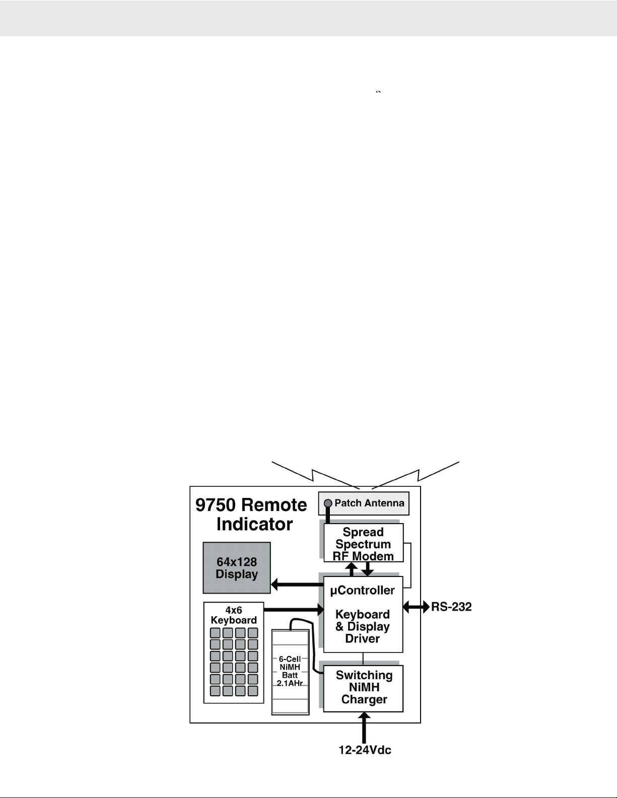
• Designed to meet or exceed all US and international standards.
• Multiple Customized Display Modes, single channel or multiple channel modes
• Reliable 2.4 GHz Frequency Hopping RF communications. Highly immune to interference and multi-path
problems. Range in excess of 500 feet indoors (LOS).
• Each 9750A can act as a terminal for any CellScale. A 9750A can monitor multiple scale channels on a single
CellScale, or multiple scales tied to multiple CellScales.
• Store up to 32 per connected CellScale ID Codes with separate Alphanumeric Names, Tare, Mode, and Totals.
ID Codes are addressed by any customer given name or number. Two user entered ID data strings are available
for each ID code. Support for up to four Bar Code entry strings.
• Easy to read annunciation of ID Names and Menu Prompts are provided on the fully customer defi ned display
screen.
• Full RS-232 output formatting offers exceptionally versatile data output. Weight data can be printed in any
desired way. The customer can add any alpha characters and/or printer formatting commands; including for-
matting for Bar Code printers. Bar Code readers can also be attached to the Comm Port.
• Manual or Automatic Data Logging into battery backed memory. Any data can be stored for later downloading
into a computer.
• Display illumination uses rugged, long life, LED backlighting coupled with a transfl ective LCD to provide
optimum display contrast under all ambient conditions from full sunlight to total darkness. The backlight
automatically turns off and on when needed to conserve battery life.
• NiMH battery pack provides up to 9 hours of continuous operation. The built in charger operates, with the
proper adapters, from 90-260 VAC (45-65 Hz), or 12-24 VDC Input (optional Cigarette Lighter Adapter avail-
able). Accessory power supplies are available to allow charging from 250 VDC as well.
• Selectable for lb., kg, g, tons, metric tons, ounces, and daN for force measurement (some units and /or units
switching may be prohibited in legal for trade units).
• Multi-mode automatic or manual weight totalizing with multiple ID registers.
• Weather resistant sealing ensures reliable operations under harsh conditions. Rugged, gasketed, PVC package
is rated to NEMA 3 and IP54.
9750A BLOCK DIAGRAM
HANDHELD RF REMOTE INDICATOR for CELLSCALE
®
Page 8 MSI-9750A RF Remote Indicator • User Guide
Page 9
MEASUREMENT SYSTEMS INTERNATIONAL
Firmware Version 5-XX for 2450 Modems
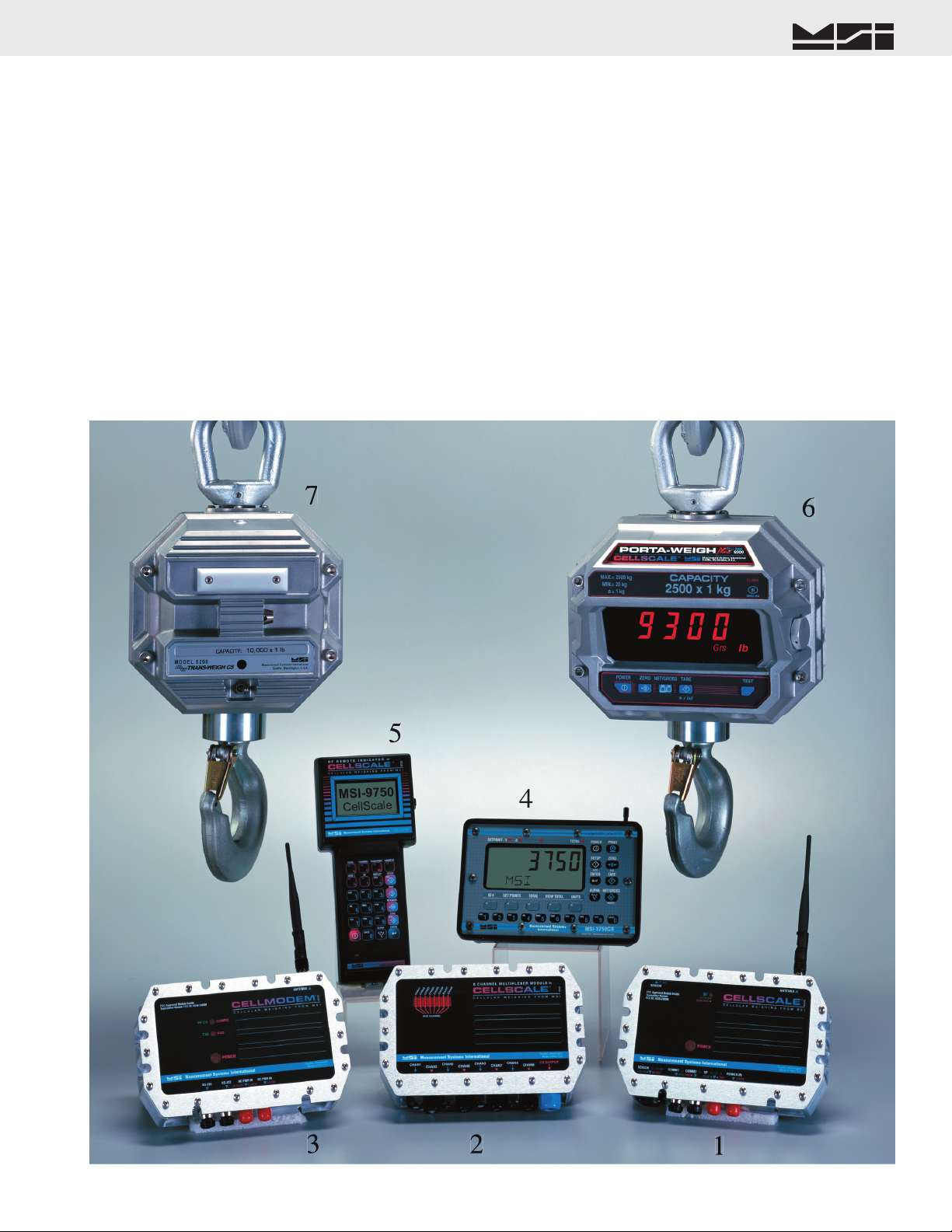
THE CELLSCALE FAMILY
2) Model 9008 Multiplexer – Allows up to eight scales with independent calibrations, to share a single CellScale
input channel.
3) Model 9020 CellModem – For interfacing peripheral devices to a CellScale.
4) Model 3750CS – Fixed mount indicator for CellScales. Capable of control and calibration.
5) Model 9750A – Portable remote indicator for CellScales. Capable of control and calibration. Can display
multiple channels.
6) Model 9300 – CellScale based Crane Scale with local LED display.
7) Model 6260CS – CellScale based Crane Scale. Available in standard capacities up to 100000 lb (50000 kg)
and by special order up to 250 tons
Model 9260 – (Not pictured) Motion Compensated Crane Scale used in scrap metal weighing.
Model 9002 Summing Box – (Not pictured) Single or Dual Channel summing of up to 4 load cells.
Model 9850 – (Not pictured) Advanced Capability Fixed mount Remote Indicator. Avail 3rd Quarter 2006.
2
4
5
6
7
MSI CellScale® System • 9750A User Guide Page 9
Page 10

The 9750A is simple to setup and use. If there are no peripheral devices such as a printer or bar code scanner,
setup consists of charging the battery, and setting the modem controls to talk to a 9000 CellScale.
The 9750A uses a high capacity Nickel Metal Hydride Rechargeable battery pack. The battery pack will power
the 9750A for up to 8 hours depending mainly on how much the LCD backlight is on. This is a custom battery
pack with over-temp and over-current protection designed for fast charging that must be replaced with MSI P/N
and can be charged at any time in the discharge cycle. NiMH batteries do have a fairly high self-discharge rate,
so if the unit is unplugged and idle for a long period of time, the batteries will require charging.
The 9750A LCD will display a low battery warning when there is about a half hour to an hour (depends on back-
light and battery age) of operating time remaining.
The 9750A is shipped with the battery pre installed. When the battery needs replacing, remove the 6 screws on
the back panel to gain access to the NiMH battery. Gently pull out the battery cable from the interior of the case.
There is a single latch on the connector that must be pushed to separate the battery cable from the 9750A. After
plugging the new battery in, stuff the connector back into the case interior, then reseal the battery cover.
CHARGER ADAPTER
The 9750A battery charger is integral to the 9750A. Input power can any source of 12-24VDC with a minimum
of 20 watts of power. MSI provides two charger sources: 1) Universal AC power: Operates from 86 to 265 VAC
45 to 440 Hz. 2) Vehicle Power: Works with vehicles with 12-24 VDC battery systems (cigarette lighter adapter).
The maximum drain on the power source is 20 watts, but this amount of drain is brief. The source current tapers
down as the battery charges. For 12V systems the maximum drain is about 1.5 amps. A 5A fuse is suffi cient to
protect the vehicle electrical system while still providing enough peak power to charge the battery. The MSI
Cigarette Lighter Adapter (MSI P/N 12674) is internally fused with a 5A fuse.
CHARGING THE BATTERY
Turn off the 9750A. Plug in the Charger Adapter in the charge port. Charging will take up to 2 hours depending
on how much the battery was discharged. The 9750A has a charge status indicator on the front panel. The charger
is in fast charge mode when the light is Red. When the light turns Green, the 9750A is ready for use.
Charge Indicator
Off External Power Not Present
Blinking Red/Grn Charge Pending. Either the battery temperature is too high, or the cell voltage is below what
is safe to fast charge. The battery is trickle charged until these conditions are cleared.
Steady Red Fast Charge in progress.
Green Fast Charge Completed. Charger enters pulse phase charge top off. You can use the system
as soon as the green light is on. However, maximum charge capacity is reached about 30
minutes after the light turns green. The Green light will pulse often while in top off phase,
less often during maintenance phases.
adapter, let it cool for 1/2 hour, and then plug it back in. This will initiate another fast
charge cycle that should only last a short time if the battery is functioning properly.
The internal charger is a multi-stage charger. The external adapter can be left plugged in indefi nitely. It will
continually pulse charge the battery preventing self discharge and keeping the battery topped off. If the 9750A is
used sporadically, MSI recommends leaving the adapter plugged in while the system is idle.
battery, turn the 9750A off, remove the power plug, then plug it back in.
HANDHELD RF REMOTE INDICATOR for CELLSCALE
®
Page 10 MSI-9750A RF Remote Indicator • User Guide
Page 11

MEASUREMENT SYSTEMS INTERNATIONAL
Firmware Version 5-XX for 2450 Modems
SECTION 2 – RF SCALE COMMUNICATIONS
The 9750A is a component of the MSI CellScale System. The CellScale system uses frequency hopping
spread-spectrum RF Modem technology transmitting in the 2.4 GHz ISM band.
RF Modems have been problematic as the RF bands are very hostile, corrupted by noise, path loss and inter-
fering transmission from other radios. Even in a pure interference-free environment, radio performance faces
serious degradation through a phenomenon known as multipath fading, a problem particularly prevalent for
indoor installations. Multipath fading results when two or more refl ected rays of the transmitted signal arrive
at the receiving antenna with opposing phase, thereby partially or completely cancelling the desired signal.
Spread spectrum reduces the vulnerability of a radio system to both interference from jammers and multipath
fading by distributing the transmitted signal over a larger region of the frequency band than would otherwise
be necessary to send the information. This allows the signal to be reconstructed even though part of it may be
lost or corrupted in transit.
Spectrum has been set aside at 2.4 GHz in most countries for the purpose of allowing compliant spread spec-
trum systems to operate freely without the requirement of a site license. In the USA, there are absolutely no
site licensing requirements. The CellScale system is also programmable for use in most European countries.
Please contact MSI for worldwide compliance information.
device, pursuant to part 15 of the FCC Rules. These limits are designed to provide reason-
able protection against harmful interference when the equipment is operated in a commercial
environment. This equipment generates, uses, and can radiate radio frequency energy and, if
not installed and used in accordance with the instruction manual, may cause harmful interfer-
ence to radio communications. Operation of this equipment in a residential area is likely to
cause harmful interference in which case the user will be required to correct the interference
at their expense.
The CellScale system uses frequency hopping which is produced by transmitting the data signal as usual, but
varying the carrier frequency rapidly according to a pseudo-random pattern over a broad range of channels, in
this case 86 discreet frequencies. These 86 frequencies are combined in different “hopping patterns” to provide 64
(0-63) separate networks. The CellScale network uses a ‘Star’ network topology. One unit, usually the CellScale,
is designated a ‘Master’. The Master transmits a sync pulse on a regular basis, providing synchronization of all
remotes in the designated Network. Thus it forms the center of a cell. MSI provides three products capable of
being the master unit: the CellScale, the 9300 Crane Scale, or the 6260 Trans-Weigh CS Crane Scale. Up to 16
remotes can access the master unit. Current MSI provided remote devices include the 3750CS Indicator, the 9750A
Handheld Indicator, the 9850 Indicator, and the 9020 CellModem. Multiple remotes can coexist on one network,
or can be easily switched to other networks as required.
The CellScale system uses TDMA (Time Division Multiple Access) to arbitrate between multiple remotes. Each
remote is assigned a specifi c time slot thus guaranteeing data throughput. The CellScale network uses a ‘Star’
network topology. One unit, usually the CellScale, is designated a ‘Master’. The Master transmits a sync pulse on
a regular basis, providing synchronization of all remotes in the designated Network. MSI provides fi ve products
capable of being the master unit: the CellScale, the Smart CellModem 9000 (not 9020), the MSI-9260 ruggedized
Crane Scale, the MSI-9300 Porta-Weigh+ Crane Scale (with local display), or the MSI-6260CS Trans-Weigh CS
Crane Scale. Up to 15 slaves can access the master unit. The 9750A is always a ‘Slave’. Multiple 9750A units
can coexist on one network, or can be easily switched to other networks as required.
For more on setting up CellScale networks, please refer to the MSI-9000 CellScale User Guide.
ANTENNA
The 9750A uses a built in “Patch” antenna with no external visible element. The patch is located in the end of the
9750A above the display. In most installed CellScale networks, the patch antenna is essentially omnidirectional.
However, in systems where the 9750A is reaching the limits of transmission range, the 9750A will achieve better
range by pointing it toward the master CellScale’s antenna.
MSI CellScale® System • 9750A User Guide Page 11
Page 12
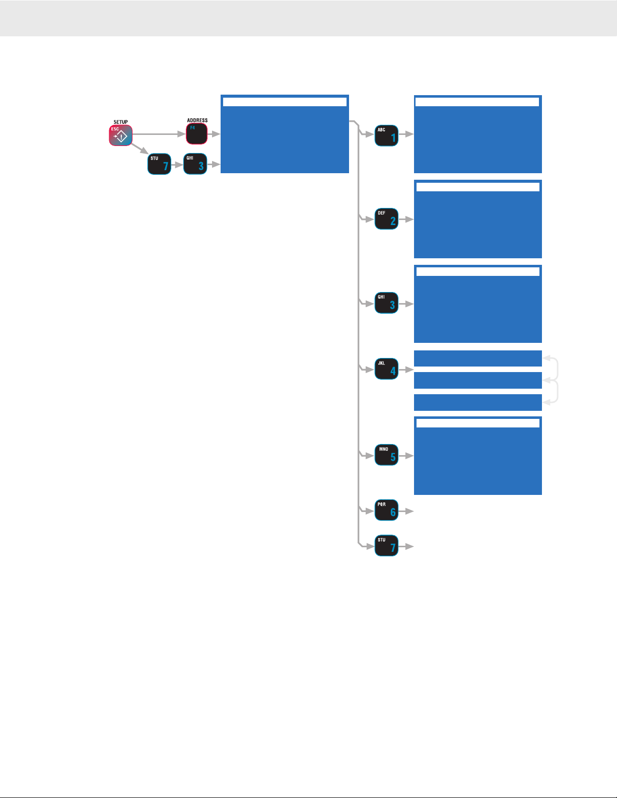
MODEM SETTINGS v2.05
1 Network Address 17
2 CS Address 17
3 My Address 57
4 Transmit Power HI
5 Timeout 1Øs
6 Advanced Settings
7 Save Settings Now
NETWORK ADDRESS
ESC exits no change
ENTER saves value
0-9 replaces value
17
min = 0, max = 63
^ incs, v decs value
CELLSCALE ADDRESS
ESC exits no change
ENTER saves value
0-9 replaces value
17
min = 5, max = 251
^ incs, v decs value
MY ADDRESS
ESC exits no change
ENTER saves value
0-9 replaces value
57
mmin = 5, max = 251
^ incs, v decs value
TIMEOUT THIS NETWORK
ESC exits no change
ENTER saves value
0-9 replaces value
1Ø
min = 1, max = 1800
^ incs, v decs value
4 Transmit Power HI
4 Transmit Power MED
Saves Settings to Memory
Shortcut
4 Transmit Power LO
See
Advanced Settings
MODEM SETTINGS v2.05
NETWORK ADDRESS
CELLSCALE ADDRESS
MY ADDRESS
TIMEOUT THIS NETWORK
The 9750A is a RF Modem connected device. The RF Modem requires setup to connect to one or more CellScales.
The 9750A stores information for all 64 possible networks. Each network setting can be modifi ed with the “Modem
Settings Menu”.
NETWORK ADDRESS – Sets the primary network
address number. Set this number to match the Network
number of the CellScale master the 9750A must com-
municate to. Ranges from 0 to 63.
CS ADDRESS – Sets the primary master CellScale ID
number. This number must match the Source Address
number of the primary master CellScale. Ranges from
5 (default) to 251. This number is usually 5.
MY ADDRESS – Any 9750A unit in a given Network
must have a unique ID number. Enter up to three digits
to designate the 9750A ID number. Ranges from 5 to
251. Make sure no other devices have this same number.
Other devices that must have unique numbers are 9020
Modems, 3750CS Indicators, and 9300 and/or 6260CS
crane scales used as slave units.
TRANSMIT POWER – Sets the RF power level between
applications power should be set to High. Reduced
energy can reduce the size of the coverage / interfer-
ence zone which may be desirable for multiple-network
applications. Always check for adequate range coverage
when using the Low setting. Only a minor improvement
in battery life (~10%) is achieved by using the Lo set-
ting.
TIMEOUT – Sets the time in seconds (0-1800) that the
9750A will wait for data from the CellScale Master. The
display will blank out if no data is received within this
time period. MSI recommends at least a 10 second time
out period to handle small lapses in transmissions. The
system defaults to 10 seconds.
ADJUST MODEM – Advanced features settings of the
Modem. See “ADJUST MODEM MENU” on the fol-
lowing page. This line also shows the fi rmware version
of the RF Modem (v2.0x).
SAVE SETTINGS NOW – Commits the settings to the
Modems Memory. The Modem settings will be automati-
cally saved at power down if changed.
SCAN NETWORK – Setting the Scan Network ON places
the network in the list of addresses reached by pressing
the ADDRESS key. Setting the Scan Network OFF still
allows you to pre confi gure the network settings, but the
Network will not be in the list of available networks.
[1]
[2]
[3]
HANDHELD RF REMOTE INDICATOR for CELLSCALE
®
[4]
[5]
[6]
[7]
Page 12 MSI-9750A RF Remote Indicator • User Guide
Page 13
MEASUREMENT SYSTEMS INTERNATIONAL
Firmware Version 5-XX for 2450 Modems
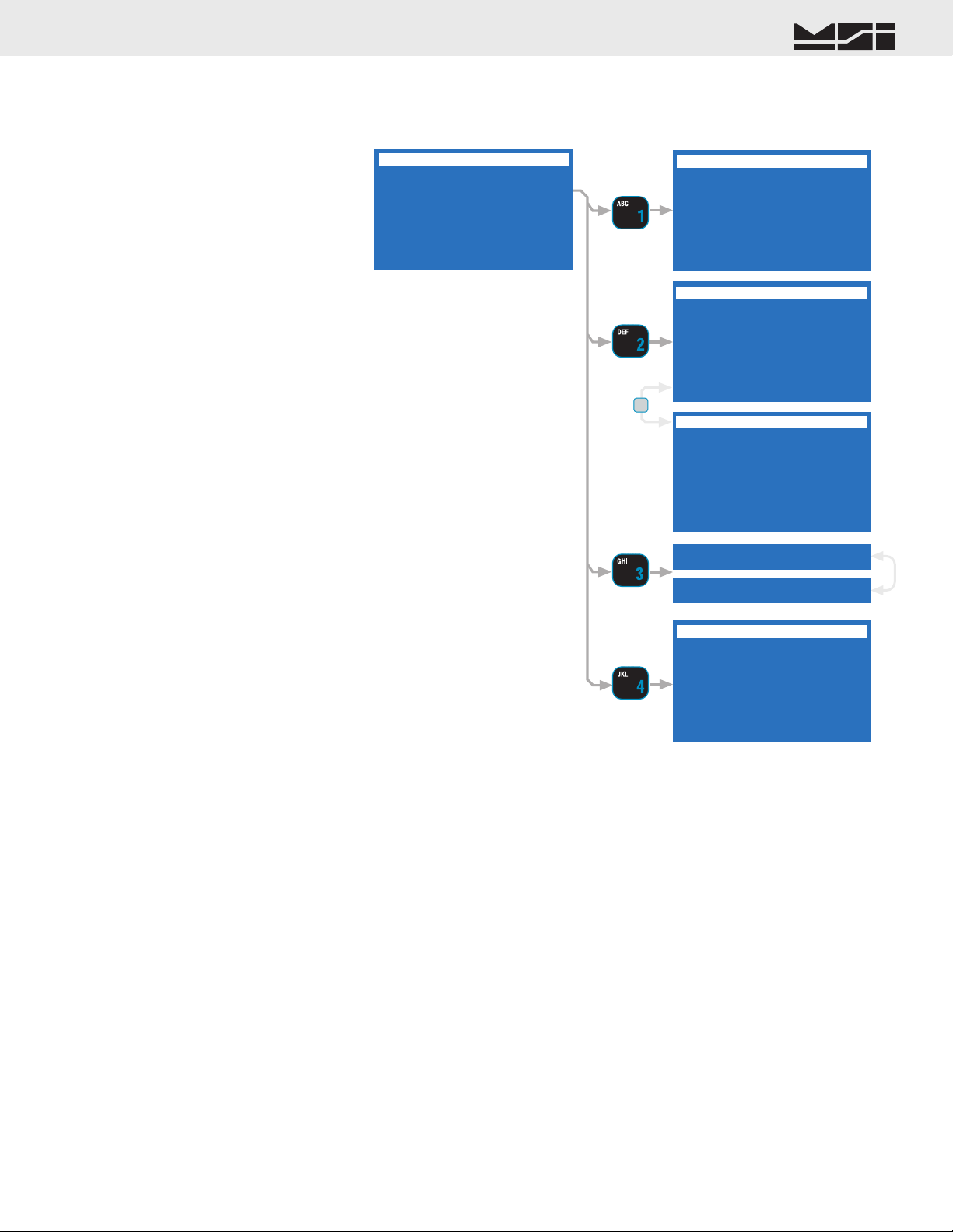
ADVANCED MODEM SETTINGS
The “ADVANCED SETTINGS’ menu provides access to some of the advanced features of the 9750A’s RF
Modem. These features are not usually needed and should be left to defaults.
1 Lock Out Key Ø
2 802.11 Avoid OFF
3 Scan Network OFF
4 Reranging 652.7 sec
Signal Strength 13Ø
Modem Ser. # ØØ-Ø2-46
ESC exits no change
ENTER saves value
Ø-9 replaces value
Ø
min = Ø, max = 255
^ incs, v decs value
1 OFF, FCC/ETSI LEGAL
2 Bands 1 & 2
3 Bands 3 & 4
4 Bands 5 & 6
5 Bands 7 & 8
6 Bands 9 & 10
7 MORE 1/2
ESC exits no change
ENTER saves value
Ø-9 replaces value
652
min = Ø, max = 655
^ incs, v decs value
3 Scan Network OFF
3 Scan Network ON
802.11b AVOIDANCE
1 Bands 11&12, France
2 Bands 1 & 10 to 12
3 Bands 1 to 6
4 Bands 6 to 12
5 Bands 1 to 3 & 11
7 MORE 2/2
7
ADVANCED SETTINGS
LOCK OUT KEY
802.11b AVOIDANCE
802.11b AVOIDANCE
RERANGING PERIOD, SEC
1) Lock Out Key – For added security in environments
where other CellScale modems are operating on the
same network, a Lock Out Key can be set which will
prevent modems from communicating. The Lock Out
key must also match in the master CellScale Modem.
DO NOT change this number from 0 unless all modem
elements are also changed as this will cause severe com-
munications problems.
2) 802.11 Avoidance – The 9750As modem can be set to
minimize interference with 802.11b RF networks in
common use for computer networks. You must deter-
mine which band the 802.11b modem is operating on
and then select the corresponding band to avoid. The
second page also includes a setting making the cellscale
legal in France. The CellScale master must also have the
same setting. DO NOT change the setting in this menu
without corresponding changes in all CellScale devices
in the network.
3) Scan Network – When On, this feature adds Network
address information to a current networks list. If this
9750A is to be used on multiple networks, turn the
“Scan Network” “ON” every time you log onto another
network that you may want to go back to. Then using
the
key, you can quickly scroll through all
stored networks.
4) Reranging – This feature sets the interval in which the
modem requests recomputation of the distance compen-
sation. The default is suitable for standard operation and
should not be altered.
The next line below Reranging gives a relative receive
signal strength. This value reports the relative signal
strength averaged over the last 10 hops. Larger values
indicate stronger signals.
The next line indicates the RF Serial Number of the
embedded modem.
ADDRESS
MSI CellScale® System • 9750A User Guide Page 13
Page 14
1) Enter the number of the CellScale network.
In this example we’ll use network 12. Use the appropriate numbers for your CellScale master. It is not necessary to enter a ‘0’
for networks below 10.
2) Press the
key. The Network Address Changes to the new Address and is
added to the Network Scan List.
It can take up to 8 seconds to log on to a new network, and for the weight data to appear. If the 9750A is unable to locate a
Master CellScale at the entered address, the message “NO NETWORK” will appear.
1
ABC
2
DEF
2
ADDRESS
Setting the Network Address (shortcut method)
1) Press
. From the “SETUP SELECT MENU” , select “MORE”
.
2) Select “RF Modem”
.
Steps 1 and 2 have a shortcut. Press SETUP followed by ADDRESS.
3) Select “Network Address”
. This calls the Network Address data entry screen.
4) Using the keypad, key in the desired Network Address (0-63). The Address used must match the Network
address of the CellScale master. Press
to store the address.
5) Select “CS Address”
. This calls the CellScale Address data entry screen.
6) Using the keypad, key in the desired CellScale Address (5-251). The Address used must match the ID address
of the CellScale master (2nd number, e.g. 23-
23)
. Usually CellScale masters are usually confi gured with
the ID Address number set to the same number as the master. Networks 0-5 usually are set to the Network
number +64 (e.g. Net 4, CS address 68). DO NOT use a CS Address below 5.
7) Select “My Address”
. This calls the My Address data entry screen.
8) Using the keypad, key in the desired My Address (5-251). The Address used must be unique within all
possible networks this 9750A is to contact. Press
to store the address.
9) Select HI, MED, or LO transmit power using the
key. Usually this should be set to HI for maximum
range.
10) Select Timeout
. The Timeout period is the time the 9750A will wait before reporting loss of updated
data from the Master. When the timeout period is completed without new data transmitted, the weight
display will change to dashes.
11) Using the keypad, set the Timeout in Seconds. A timeout from 5 to 20 seconds is recommended (10 seconds
is the default). Press
to store the timeout.
12) Set this network active by pressing
. From the ADVANCED SETTING menu, choose
ON. This
places the Network in the 9750’s active network list, allowing use of the
key to switch the
9750A to this and other stored Modem settings. Resturn to the Modem settings menu by pressing
.
13) Store the Modem settings by pressing
. The unit will pause with a key tone while the settings are
stored.
14) Return to weight reading (assuming there is a CellScale at the address you just set) by pressing
or press
to return to the Setup Menu. There may be a delay while the new address request is processed
by the CellScale.
Setting the Network Address (standard method), and RF Modem Confi guration
Access to all user configured parameters in the RF Modem.
CS Address equals Network number (e.g. 12-12, 1-65, 9-9, etc.), unless the network number is 5 or below, then
the CS address equals the Network number + 64
CONFIGURING FOR MULTIPLE NETWORKS
The 9750A can access multiple CellScales by switching Networks. A press of the
key will change the
network allowing the 9750A to monitor and control different scales. Because each CellScale has both a network
and a CS address, these must be set up with the “SETUP RF NETWORK” menu and made active. The 9750A
®
®
can access up to 64 CellScale based Networks. It takes the 9750A from 4 to 8 seconds to switch networks, as
it has to sync with a new hopping pattern. Networks that are inactive but were set up can be reached by typing
the Network Address (0-31) followed by the
key. New networks not previously set up can also be
reached this way, but the modem confi guration will set to defaults.
HANDHELD RF REMOTE INDICATOR for CELLSCALE
ADDRESS
®
ADDRESS
ADDRESS
SETUP
[5]
[3]
[1]
[2]
[3]
ENTER
ENTER
[6]
[7]
ENTER
[4]
[3]
ADDRESS
ESC
[7]
ESC
Page 14 MSI-9750A RF Remote Indicator • User Guide
DISPLAY
Page 15

MEASUREMENT SYSTEMS INTERNATIONAL
Firmware Version 5-XX for 2450 Modems
Transmit power set to HI.
Time out set to 10 seconds.
My Address remains unchanged and is the same in any network.
TROUBLESHOOTING RF CONNECTION PROBLEMS
Most connection problems are caused by improperly set up RF Networks. Both the 9750A and the master CellScale
unit must have identical Network numbers. In addition, the CS Address must match on both units. If the Net-
work and/or CS Address of the CellScale is in question, you might have to connect a terminal to the CellScale to
determine its exact settings. See the CellScale manual for this procedure. Verify the 9750A settings are proper
by using the “CONFIGURE RF MODEM” procedure. Each slave device (9750As, 3750CS, and 9020s) must
have unique “My Address”.
A common cause of perceived problems is the “Phantom Network”. This occurs when there is a confl icting Net-
work within broadcast range. Multi-CellScale sites must be planned carefully so that there are never two master
CellScales on the same Network within range of each other. Since the CellScale can broadcast for miles with
good LOS (line of sight) conditions, this consideration is very important. If you suspect your 9750A has locked
on to a distant (Phantom) network, try switching both the master CellScale and the 9750A slave to another unused
Network. MSI advises avoiding Network #0 when possible, as this is the Modem default, and therefore most
likely to be found on units that were left in default settings.
Weight displays, but 9750A keys don’t work
This is a result of changing the CS Address in the slave 9750A so it no longer matches the master CellScale. The
modem is still registered by the master CellScale, but control codes are not received because the master assumes
the codes are intended for a different slave CellScale. Change the CS Address in the 9750A back to the number
that matches the master CellScale.
This is usually a result of being in or near an “RF Null” zone. Because of multiple echoes of signals there is
sometimes locations that are particularly problematic even for Frequency Hoppers. Usually moving the antenna
location even a small distance can clear up this kind of problem. Avoid placing the antenna up against large metal
walls. Concrete walls can also be problematic due to their high moisture content. The antenna should be at least
4 inches away from large metal or concrete surfaces. Mounting the antenna too close to a wall has the effect of
making the Antenna directional and can attenuate the output.
Antenna placement is the most common cause of poor range. Check that the RF power level of the master and
slave units is on “High”. Radio signals in nearby bands that have signifi cant power can also reduce range. Lon-
gest range will always be achieved by Line-of-sight (LOS) antenna placement. Any obstacle that interferes with
LOS will reduce the range. Signifi cant blocking is caused by metal buildings, solid concrete walls, and any other
object that has fairly high electrical conductance. Raising the master antenna higher can help. Just moving the
relative antenna placement a short distance might fi nd an RF “path” that will improve distance. The CellScale
can sometimes take advantage of refl ecting surfaces to get around obstacles. CellScale device antennas should
always be placed in vertical polarization; that is the shaft of the antenna should be perpendicular to the earth,
not parallel. It is OK to mount the Antenna upside down. This is a good solution when an antenna is mounted on
the ceiling for communication with CellScale components in the building. The 9750A internal antenna is mildly
directional. Aim the end of the 9750A towards the CellScale master for longest range. In short range applications
(LOS and <500 feet) the 9750A is essentially omni-directional.
Some CellScale master units can take advantage of higher gain antennas.Yagi Antennas can greatly improve the
range of a CellScale system when installed on the master CellScale. These multi-element antennas are highly
directional and must be aimed towards the 9750A area of operation.
The CellScale system is designed using state of the art RF Modems. However there will be conditions and envi-
ronments where communication of telemetry is sporadic or impossible. Jamming of FHSS systems is diffi cult,
but not impossible. Bear in mind that the most likely source of jamming will be other CellScale systems on the
same network, within transmission range. The new breed of wireless phones (not Cell Phones) operating in the
2.4GHz bands will not jam a CellScale. However the CellScale may be received on the wireless phone and will
sound like a background ticking noise. Standard Cell Phones do not operate in the same bands as the CellScale and
will not interfere with CellScale components. However, a Cell Phone repeater tower nearby might have enough
out of band interference to reduce the range of CellScale equipment.
MSI CellScale® System • 9750A User Guide Page 15
Page 16

1) Place the 9750A in close proximity of the master CellScale unit. Make sure communications are good
(weight is on the display, all data types have been reported).
2) Press the function key programmed for “RF Site Testing”. The bottom right side of the display will read
“RF xx%”. The per cent reading indicates the ratio of successful transmissions. It will start low at fi rst,
then creep up. It should approach 100%, with an average reading of >96%.
If the reading does not achieve >96% within 1 minute try changing the CellScale Master device (MSI-9000, MSI-6260, MSI-9300, etc.) to a new network.
master.
3) Now start walking around the site with the 9750A. If the RF% reading starts down, stop and wait. Aim the
9750A towards the CellScale master and see if the RF% reading begins to rise again. If the display suddenly
reads “NETWORK”, you have lost communication. Return to the last place that communications were
working and wait for the 9750A to reconnect. In this way you can establish the range of adequate com-
munications, and note any areas with severe RF dropout. The location and height of the CellScale master
also plays a big part in range so be sure to run the site test with the CellScale in typical locations used in
your application.
4) Cancel the RF Site Test by pressing the function key again. If needed for some other function, reprogram
the function key.
The 9750A provides a means to check the effi ciency of RF transmissions using the RF Site Testing function.
Program a function key (use the procedure in Section 4) to “RF Site Testing” to run the test.
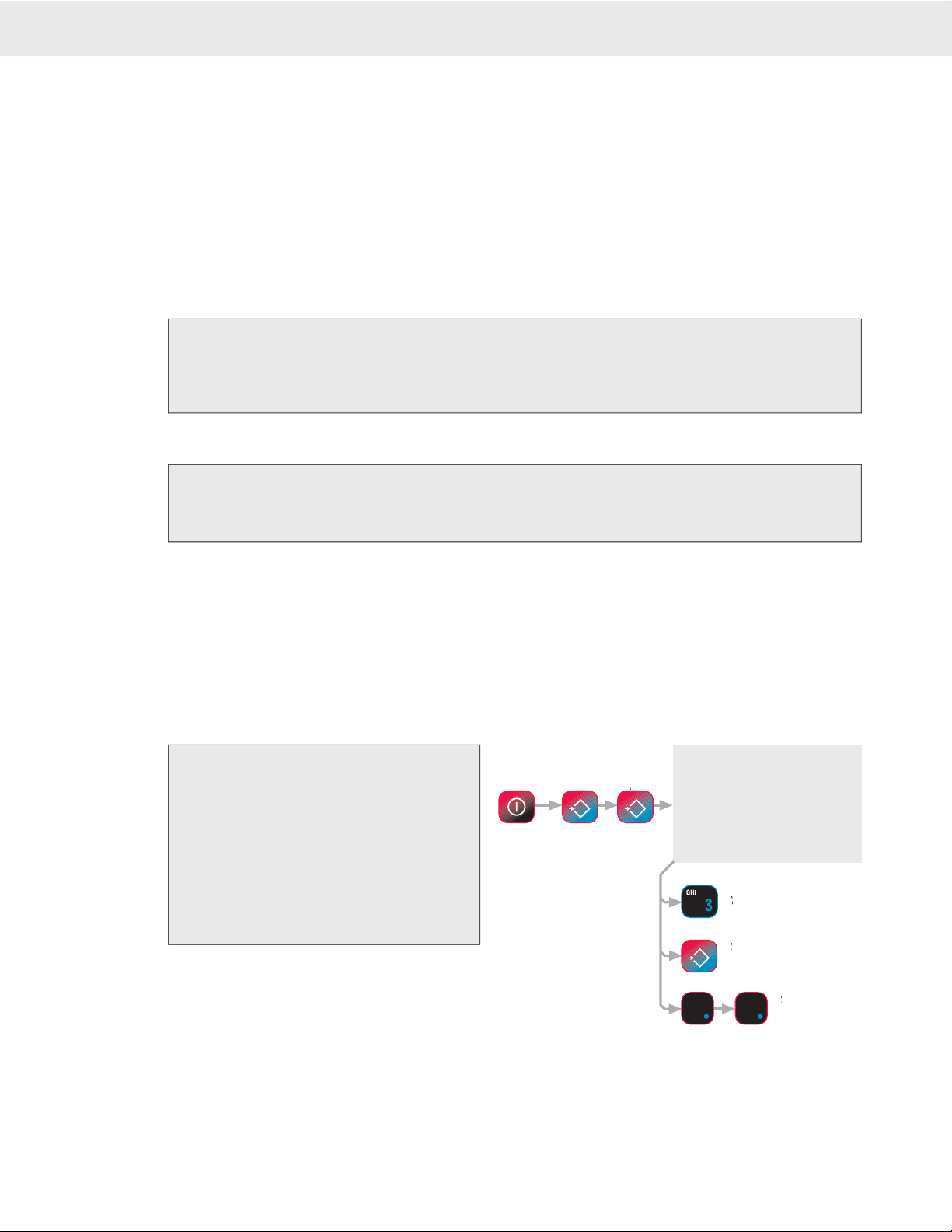
CELLSCALE NETWORK AUTO SCAN
For installations where multiple CellScale systems are present, the 9750A can scan every network and determine
if a CellScale master device is broadcasting. Found CellScales can be copied directly into the RF Scan List at the
end of the test. Turn on all CellScale masters (MSI-9000, 6260CS, 9300, etc.) that your 9750A will be used with.
Ensure that each CellScale master is on unique network addresses (see product User Guides).
1) Press
followed quickly by
.
It doesn’t matter if the 9750A is on or off.
2) Press
to start the scan. The 9750A will begin a progressive scan of all 64 (0-63) net-
works.
3) Every CellScale master found will display along with its address. The end of the test will be indicated by
the display reading “ENTER Copy to Scan”.
4) If you want to store the found CellScale addresses, push
. The display will read “COPYING RF
SCAN”.
5) Press
to return to weight reading.
HANDHELD RF REMOTE INDICATOR for CELLSCALE
®
POWER
NET/GROSS
DISPLAY
ESC
ENTER
Page 16 MSI-9750A RF Remote Indicator • User Guide
Page 17

MEASUREMENT SYSTEMS INTERNATIONAL
Firmware Version 5-XX for 2450 Modems
SECTION 3 – SCALE OPERATION
To Turn On the Power
POWER
If the system fails
to connect in 8 seconds or
less, press the ADDRESS
key to select a different
Network, or enter the
number of a working net-
work and press ADDRESS.
If this fails check RF
network setups, or decrease
the range between the
CellScale and the 9750A.
1) Press and hold
for 1 second
. The display should light and show the MSI
Logo.
2) The LCD then displays “MSI-9750A-5”, the Network currently loaded as the active
Address, and the software version number. The display will read “Searching Add
XX” while establishing communications with the master CellScale.
3) Next the RF network is contacted. If the network is functional, the display switches
to normal weight display mode. This usually takes 4-15 seconds. If the Network
is not available, the screen will continue to display the desired Network. Either
change the Scan Network with the
key or turn on the proper CellScale
Master. Use of the
key assumes that multiple networks have previ-
ously set up. See “Setting the Network Address” on page 12.
Each CellScale is capable of hosting up to 32 independent scale inputs. Since any 9750A can communicate with
any CellScale, theoretically hundreds of scales can be controlled by a single 9750A. Because of the complexi-
ties of multiple channel setups, the 9750A is designed to access channels that have been previously setup in the
CellScale through its terminal interface or virtual meter interface.
Channels in the CellScale are organized by the A/D input channel followed by a Mux sub channel value. The
standard CellScale has two A/D inputs, but can be ordered with four A/D inputs with the addition of a second
A/D Converter module. Each A/D channel can be further divided by the use of external multiplexers into eight
additional inputs per channel, providing a total of up to 32 independent scale inputs. The channels are designated
like this:
Channel (A/D 1-4)
Sub channel (mux 1-8)
The channel will vary from 1-4 and the sub channel from 1-8. In addition the CellScale provides channel 5 for
slave CellScales, and channel 6 for math channels. Math Channels allow the user to add or subtract channels from
each other or perform other mathematical manipulations of the data. All calibration data for the 32 channels is
stored in the CellScale and is independent of the 9750A. Therefore any 9750A can receive calibrated data from
any CellScale provided the RF network is set up properly.
It should be noted that sub channels are useful even when the multiplexer option is not used. For example, chan-
nel 1-1 could be calibrated as a 1000 x 0.5 kg scale, and channel 1-2 as a 2000 x 1 kg scale, making a dual range
platform (of course this assumes the platform is capable of handling 2000 kg). This will work as long as the main
channel remains constant. So, in theory, 1 platform could be calibrated as 8 independent scales. This works because
the CellScale does not know or care if a Multiplexer is actually present. It treats the input as a separate scale.
The 9750A reads multiple channels by using the Scan list index. The “Scan list” is stored in the CellScale, with
up to 32 channels present in the list. The fi rst number in the scan list is called the Scan List Index number. The
CellScale can have up to 32 Scan List indices. A scan list can include “Math Channels” which provide a means
to digitally add the results of multiple scales.
When dealing with multiple channels it is recommended that you set up the display to always show either the
Channel Number or the Channel Name or both. This will help in identifying which scale you are observing.
SELECTING THE ACTIVE CHANNEL
Before standard scale functions are performed, you must select the “Active Channel”. The “Active Channel” is the
channel that commands such as Zero, Tare, Total, etc. will be performed on. On single channel display screens,
the channel shown is the active channel. On Multiple channel displays, you must highlight the desired channel.
This is done with the Cursor Keys. Once highlighted you can perform all the standard scale functions (except
Total and View Total, these only work from the single channel display). You can also switch to the single channel
display by pressing the
key.
See the “DISPLAY MODE SETUP” section 7 for information on multiple and single channel weight display modes. For more information on Scan Lists and multiple
scale channels, please refer to the CellScale MSI-9000 Users Guide.
POWER
ADDRESS
ADDRESS
DISPLAY
MSI CellScale® System • 9750A User Guide Page 17
Page 18
1) Press the
key
. The weight display will temporarily display dashes while it
queries the CellScale for the next channel information.
2) Keep pressing the
key as desired until the channel of interest is displayed.
been altered)
CHANNEL
2
F2
CHANNEL
TO SELECT THE DISPLAY CHANNEL
As mentioned above, the 9750A will access any channels setup in the CellScale. It does this with the “CHAN-
NEL” function. Use the
key to step from channel to channel as dictated by the Scan list stored in the
CellScale. If the CellScale has only one scale channel defi ned, only 1 display mode is necessary. This is usually
®
®
the case for MSI-6260CS, MSI-9300 Crane Scales, and other single load cell systems. However, even single load
cell systems can have math channels defi ned to add functionality.
For systems with multiple scales attached to any given CellScale the setup procedure is:
1) Program the CellScale Scan List as required (see the CellScale Manual). It is recommended that each channel
is assigned a channel name to aid in identifying the scale in various display modes.
2) Optional, but recommended so you can readily identify which scale you are monitoring and controlling
– Program the display mode to show the Channel Name, or Channel Number, or both with the Display Setup
procedures in Section 7.
To Change the Scale Channel (Single Channel Display)
1) Using the numeric keys, input the number (1-32) corresponding to the desired channel in the
scan list.
2) Press the
key
. The weight display will temporarily display dashes while it
queries the CellScale for the desired channel information.
JKL
CHANNEL
To Change the Scale Channel Using Scan List Position (Single Channel Display)
To Change Scale Channel Using the Channel Number (Single Channel Display)
1) Using the numeric keys, input the number corresponding to the desired channel
number. Use the decimal point as the channel-subchannel separator.
is ignored by the CellScale.
2) Press the
key
. The weight display will temporarily display dashes
while it queries the CellScale for the desired channel information.
1
6
PQR
DISPLAY
EXIT
ABC
F2
CHANNEL
In CellScale systems with multiple channels, you can choose to see more than one channel at a time (See Display
Setup in Section 7). In order to zero, tare, or totalize with channels in a multiple channel display, you must fi rst
select the channel to operate on. This is referred to as the “Active” channel, because this is the only channel that
any scale function can be performed on.
To Select the Active Channel (multi-channel display)
1) Highlight the channel you wish to make Active by pressing the UP (
) or DOWN (
) cursor keys.
2) Once highlighted you can Zero the channel, set and clear Tare, and switch between Net and Gross with the
key, just press the appropriate key. For Total, View Total, Statistics and other ID functions,
you must switch the display to the single channel display by pressing
.
To Change a Channel in the Multi-Channel Display
1) Highlight the channel you wish to change by pressing the UP (
) or DOWN (
) cursor keys.
2) Once highlighted enter the scan list position (1-32) or the channel number (1-1 to 6-32 using the decimal
point for the sub channel entry). Then press
.
HANDHELD RF REMOTE INDICATOR for CELLSCALE
CHANNEL
®
CHANNEL
CHANNEL
CHANNEL
CHANNEL
[F2]
[F2]
[F2]
^
NET/GROSS
DISPLAY
^
CHANNEL
Page 18 MSI-9750A RF Remote Indicator • User Guide
v
v
Page 19
MEASUREMENT SYSTEMS INTERNATIONAL
Firmware Version 5-XX for 2450 Modems
To Switch Between Multi-Channel Display and Single Channel Displays
1) Highlight the channel you wish to see in the single channel mode by pressing the UP (
) or DOWN (
)
cursor keys.
2) Once highlighted press
. The highlighted channel will appear in the single channel mode.
3) Perform any scale function while in the single channel mode.
4) To return to the multi-channel display, press
.
When a multi-channel display mode is selected that shows fewer channels than are available from the CellScale,
the user can view all channels with the page mode.
Any channel can appear on any page by changing the preset channel using the “To Change Scale Channel...”
procedure. This allows a primary channel to show always, and secondary channels to change using the
key. This applies very well to the 3 channel preset display where one channel is large and the other 2 channels
are small.
To Change to the Next Page
Press the
key. The next group of channels appears. The action of the
key is circular, return-
ing to page 1 after the last page.
To Copy the Current Page
Sometimes it is advantageous to copy the current page and then make channel changes on the new page.
1) Press the
key. The entire screen will reverse.
2) Press the
key. The new copied page will appear. Make modifi cations with the enter channel pro-
cedures as desired.
To Delete the Current Page
1) Press the
(SPACE)
key.
2) Press the
key. The current page will be deleted and the display will revert to the fi rst page.
To Move Around in Pages
If you have many preset pages, you can move directly to pages by number entry.
1) Enter the number corresponding to the page you wish to see.
2) Press the
key. The new page will appear.
1) In single channel mode, go to step 2. In multi-channel mode, highlight a channel
with the up (
) or down (
) cursor keys to make it active.
2) Press
. The weight reading must be stable within the motion window for
the zero function to work. The display temporarily reads “ZEROING” and then
“ZEROED” after the CellScale acknowledges the command. The scale digits
display 0 (or 0.0 or 0.00, etc..). The backup memory in the CellScale stores the
zero reading, and can restore it even if power fails.
instantly, but the scale will zero.
ZERO
CLR
0
ZERO
Sets the zero reading of the scale. Use the
key to take out small deviations in zero when the scale is
unloaded. (See “TARE SET” for zeroing (Taring) package or pallet weights)
To Zero
Zero Rules for Use:
1) Works in GROSS mode or NET mode. Zeroing while in Net mode will zero the gross weight causing the display
to show the negative Tare value.
2) The scale must be stable within the Motion window. The scale will not zero if the motion detect annunciator
is on. The CellScale will “remember” that it has a zero request for 2 seconds. If motion clears in that time,
ALPHA
ENTER
ALPHA
DISPLAY
DISPLAY
ALPHA
^
v
ALPHA
[0]
ALPHA
ALPHA
ZERO
ZERO
^
v
ZEROING
ZEROED
MSI CellScale® System • 9750A User Guide Page 19
Page 20
the scale will zero.
3) The scale will accept a zero setting over the full Range of the scale (NTEP and other Legal-for-trade models may
have a limited zero range). Zero settings above 4% of full scale will subtract from the overall capacity of the scale.
For example if you zero out 100 lb. on a 1000 lb. scale the overall capacity of the scale will reduce to 900 lb. plus
the allowed over-range amount.
TARE
Tare is typically used to zero out a known weight such as a packing container or pallet and display the load in
NET weight. A Tare value is entered in either of two ways:
key is pressed, the current weight is zeroed and Net Weight is
displayed.
2) KEYBOARD TARE – Using the numeric keys, the operator keys in the desired Tare Weight then presses the
Key.
For Pushbutton Tare
To Clear Tare and Revert to Gross Mode
If the goal is to see the Gross Weight, use the Net/Gross key instead.
T
ARE
T
1) In single channel mode, go to step 2. In multi-channel mode, highlight a channel
with the up (
) or down (
) cursor keys to make it active.
2) Press
. The current Gross Weight will be stored in the Tare register and
the weight mode will change to NET (single display modes).
0
SPACE
T
1) In single channel mode, go to step 2. In multi-channel mode, highlight a channel with the
up (
) or down (
) cursor keys to make it active.
2) Press
followed by
. The Tare value will clear and the scale returns to the GROSS
mode.
Alternate method: Remove all weight from the scale (Gross Zero) and press TARE. The message display temporarily reads “TARING”.
To Keyboard Tare
Tare - Rules for Use:
When in the NET mode, the TARE is not cumulative, all the weight is tared off (to Net zero).
2) The motion annunciator must be off. The weight reading must be stable.
3) Setting or changing the tare has no effect on the Gross zero setting.
4) Taring will reduce the apparent over range of the scale. For example, taring a 10 lb. container on a 60 lb.
scale, the scale will overload at a net weight of 50 lb. (60-10) plus any additional allowed overload (usually
~4% or 9d).
5) The scale stores the Tare value in the current ID Code memory until cleared. Each available ID Code can
store independent Tare values.
2
0
SPACE
DISPLAY
EXIT
5
MNO
3
T
1) In single channel mode, go to step 2. In multi-channel mode, highlight a channel with
the up (
) or down (
) cursor keys to make it active.
2) Using the numeric keys input the value desired. In this example we’ll use 0.5 lb. as
a Tare Value. Press
. The Enter Line displays “0.5”.
. The Enter Line displays “0.5”.
. The Enter Line displays “0.5”.
3) Press
to place the value in the Tare Register (Current Channel, current ID).
The display reads “TARE SET” when the CellScale responds. All subsequent read-
ings have the Tare value subtracted and are displayed in “NET” weight.
To View the Tare Value
T
ARE
T
1) In single channel mode, go to step 2. In multi-channel mode, highlight a channel with
the up (
) or down (
) cursor keys to make it active.
2) Press
followed by
.
3) The display shows the current Tare value
Pressing ENTER again allows the Tare value to be edited.
TARE
HANDHELD RF REMOTE INDICATOR for CELLSCALE
®
TARE
TARE
^
[0]
TARE
^
v
TARING
v
TARE
^
v
[0] [.] [5]
^
ENTER
Page 20 MSI-9750A RF Remote Indicator • User Guide
v
TARE
Page 21
MEASUREMENT SYSTEMS INTERNATIONAL
Firmware Version 5-XX for 2450 Modems
TARE SETTINGS
-CHANNEL NAME or NUM-
1 Disable Auto Clear
2 Set Clear on Minus
3 Set Clear on Total
4 Tare by Product ID
5 Same Tare All ID’s
Shortcut
TARE SETTINGS
ESC
!
SETUP
T
ARE
T
6
PQR
7
STU
1) In single channel mode, go to step 2. In multi-
channel mode, highlight a channel with the up
(^) or down (
) cursor keys to make it active.
2) Standar d Method - Press
. Se lect
“MORE”
. Select “Tare Setup”
.
Shortcut Method - Press
followed by
.
The 9750A is capable of storing Tare values through the use of the ID Codes. Each ID code stores an independent
Tare. See Section 3 “ID Codes” for more information.
SETUP TARE MENU
Programs the automatic TARE Clear function (Auto Clear), and the various Tare Modes including a means to
disable Tare.
The Auto Tare Clear is intended to automate loading operations where packaging must be tared out, but there is a
risk that the operator will forget to re tare each new package. It does this by automatically clearing the tare value
and reverting the weight mode back to Gross. The Setup Tare menu permits three modes of Auto Tare Clear: 1)
Disabled. 2) Set Clear on Minus - When the Net Weight goes negative (as it will when a tared package is removed),
the Tare value is cleared and the weight mode reverts to Gross. 3) Set Clear on Total - When the Total function
is enacted, the Tare value is cleared and the weight mode reverts to Gross.
4-5 UNIVERSAL TARE
The Universal Tare feature allows a single Tare value to be shared by all ID Codes. With “Same Tare All IDs”
enabled the individual Tares stored with each ID Code are ignored (but not erased). Selecting “Tare by Product
ID” will restore the original Tare values. Universal Tare is intended for those applications where a common car-
rier or pallet is used, but multiple ID Codes are necessary for data collection. To select Universal Tare choose
“Same Tare All ID’s” on the TARE SETUP MENU. This effects all IDs on any given scale channel, but not the
IDs associated with other scale channels.
Tare Settings Menu
Set Auto Clear Mode with the 1-3 keys. Only 1 item from 1-3 can be enabled at a time. Set the Universal Tare
mode with the 4-5 keys.
1 Disable Auto Clear – Pressing the
key turns off the function (default).
2 Set Clear on Minus – When the Net Weight goes negative (as it will when a tared package is removed), the
Tare value is cleared and the weight mode reverts to Gross.
3 Set Clear on Total – When the Total function is enacted, the Tare value is cleared and the weight mode reverts
to Gross.
4 Tare by Product ID – Each ID has a unique Tare when this selection is chosen (default).
5 Same Tare All ID’s – Pressing the
key enables the Universal Tare Mode.
Switches the display between Net and Gross modes. Net Weight is defi ned as Gross Weight minus a Tare
Weight.
To Switch Between Net Mode and Gross Mode press the
key.
The
key will only function if a Tare value has been established for the current channel and the Tare
Mode is “NET/GROSS”. The Net/Gross function will affect all meters displaying this channel.
Switching back to Gross mode from Net mode will not clear the Tare value. This allows the operator to use the Gross Mode temporarily without having to reestablish
the Tare value. Only manually clearing the Tare or setting a new Tare will change the tare value held before switching into Gross Mode. In displays that include
the Net and Gross readings, the NET/GROSS key has no effect since both weight types are already displayed. However, other channels displaying just one weight
type will change.
returns to the Net Mode. The only way to return to permanent Gross readings is to clear the Tare (see Clear Tare procedure).
[7]
TARE
NET/GROSS
v
SET UP
[6]
SETUP
[1]
[5]
NET/GROSS
MSI CellScale® System • 9750A User Guide Page 21
Page 22
Allows easy weight units conversions. Up to 8 Units are available. See “SETUP UNITS” in the CellScale Manual
for details on activating the available units. Since Units are stored with each ID Code, the menu item for chang-
ing units is found in the “Product ID Codes” Menu. See section 3. Alternately, if changing Units is a common
operation, a Function key can be programmed for the task.
For example, if
is programmed for UNITS, then
change the current unit by pressing
. Each subsequent available unit will be found with repeated presses of
the
key.
Peak Hold is disallowed in Legal-for-trade systems.
Allows monitoring peak weight. Uses a special mode of the CellScale’s A/D converter for capturing transient
events.
To Capture Peak Weight Readings
1) Program a
key for “Toggle Peak Hold” (See Section 4).
2) Turn on the Peak Hold mode by pressing the selected
key. The display reads “PN” for Peak
Net readings, or “P” for Peak Gross to indicate peak hold mode is enabled. The display will only update
when a greater value than previously recorded is detected.
To Clear Peak Weight Readings
Turn off the Peak mode by pressing the
key programmed as “Toggle Peak Hold”. The display
reverts to Gross or Net and clears the peak value from memory.
To Start the Display Test
1) Press the
key followed quickly
by the
key. The MSI-9750A “Watch
Network” screen will appear.
2) Press the
key. The display test will
start. Each test screen will last 2 seconds.
3) To freeze on any screen, press the
key. To
continue the display test, press
again.
4) To return to the weight mode display, press
Peak Hold captures data at a reading rate set up by the CellScale A/D parameters. For High Speed Peak Hold, use a faster A/D rate. See CellScale Manual.
SEND / PRINT
Sends the current displayed reading to the Comm Port, the Data Logging Memory, or to a remote RF Host. Any
or all weight, time, date, and scale parameter functions can be printed as set in the Print Setup Mode (Section 9).
The action of the
key is controlled by the function key setup (Section 4).
Starts a display test to observe all display characters.
Sequences through
all Fonts and test
screens. 2 seconds
per screen.
o return to the
startup screen
o return to the
weight display
T
o hold current screen
ESC
!
SETUP
ESC
!
SETUP
DISPLAY
EXIT
DISPLAY
EXIT
POWER
T
[F2]
HANDHELD RF REMOTE INDICATOR for CELLSCALE
[F2]
[F2]
FUNCTION
FUNCTION
Send/Print
POWER
ESC
TARE
FUNCTION
[3]
[3]
Page 22 MSI-9750A RF Remote Indicator • User Guide
Page 23
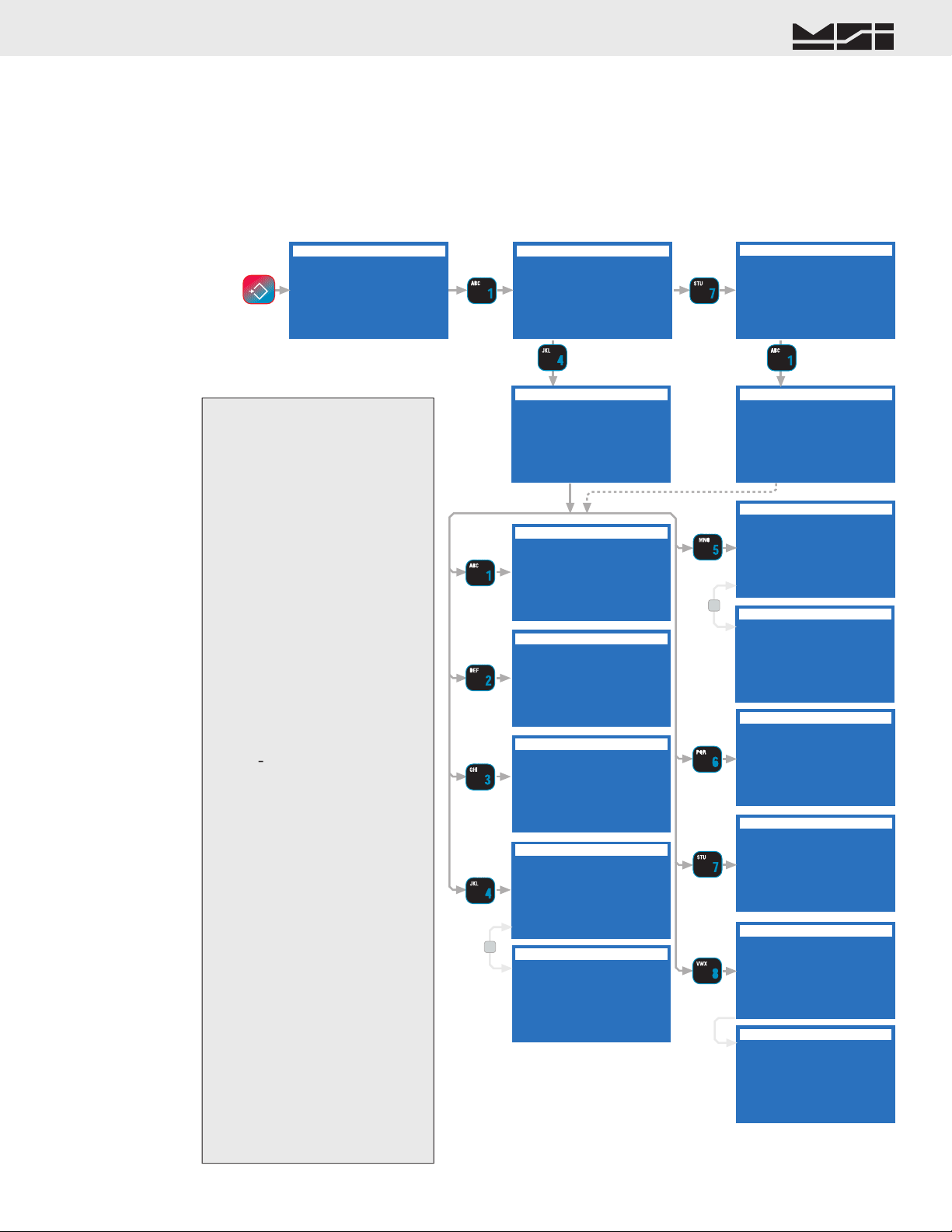
MEASUREMENT SYSTEMS INTERNATIONAL
Firmware Version 5-XX for 2450 Modems
SETUP SELECT MENU
1 Function Keys
2 Set Points
3 System
4 Password Locks
5 Display Preview
6 Total
7 MORE 1/2
FUNCTION KEY ASSIGNS
1 F1 is Add to Total
2 F2 is Next Channel
3 F3 is Send to CS
4 F4 is Next Address
5 F5 is View Total
6 F6 is Next Prod ID
7 Enter-FKey Assigns
Any Number Key 1-6
F4 shown for example
SELECT FOR F4 FROM
1 Standard Functions
2 Chan, ID, and Addr
3 Total, Stats, Tests
4 Send and Printing
5 Edit Print & BarCd
6 Text Messaging
7 Datalog 8 Set Pts
CHANGE F4 TO
1 Print 9750 Comm 1
2 Send All & Print
3 Send to CS Host 1
4 Print & Send Host 1
5 Send to CSRF Host 3
6 Print & Send Host 3
7 MORE 1/2
CHANGE F4 TO
1 Send to CSRF Host 4
2 Print & Send Host 4
3 Send to CSRF Host 5
4 Print & Send Host 5
5 Print Aux to Comm 1
6 Start/Stop Comm 1
7 MORE 2/2
7
SELECT FOR E1 FROM
1 Standard Functions
2 Chan, ID, and Addr
3 Total, Stats, Test
4 Send and Printing
5 Edit Print & BarCd
6 Text Messaging
7 Datalog 8 Set Pts
ENTER-FKEY ASSIGNS
1 E1 is Clr Last ∑
2 E2 is Back Channel
3 E3 is Print Comm 1
4 E4 is Back Address
5 E5 is View Grand ∑
6 E6 is New Prod ID
Any Number Key 1-6
ENTER-F1 shown
for example
CHANGE F4 TO
1 Disabled
2 Default
3 Disp Date & Time
4 View Totals
5 Display Set Points
6 Clear Latched SP’s
7 Toggle Peak Hold
CHANGE F4 TO
1 Enter ID String 1
2 Enter ID String 2
3 New Product ID
4 Show Last Channel
5 Show Last Prod ID
6 Show Last Address
7 Clear ID & Bar Strs
CHANGE F4 TO
1 Clear Last Total
2 Show Statistics
3 SHow Grand Totals
4 RF Site Testing
5 Display Test Chars
CHANGE F4 TO
1 Edit CS Print Str
2 Edit Print String
3 Edit CSRF Host 3
4 Edit CSRF Host 4
5 Edit CSRF Host 5
6 Clear ID & Bar Strs
7 MORE 1/2
CHANGE F4 TO
1 Store to Memory 1
2 Store to Memory 2
3 Store to Memory
4 Aux to Memory 1
5 Aux to Memory 2
6 Aux to Memory
7 Data Logging Cntl
CHANGE F4 TO
1 Send Message to 1
2 Send Message All
3 Send Message to 3
4 Send Message to 4
5 Send Message to 5
6 Reply Last Message
CHANGE F4 TO
1 Enable Set Points
2 Disable Set Points
3 Enable/Disable SP’s
4 Set Pt Momentary
5 Set Pt On
6 Set Pt Off
7 Set Pt Push On/Off
SELECT SET POINT
ESC exits no change
ENTER edits value
0-9 replaces value
min = 1, max = 32
^ inc, v decs value
CHANGE F4 TO
1 Get Barcode 1
2 Get Barcode 2
3 Get Barcode 3
4 Get Barcode 4
5 Get All Barcodes
7 MORE 2/2
7
SETUP SELECT MENU
FUNCTION KEY ASSIGNS
SELECT FOR F4 FROM
ENTER-FKEY ASSIGNS
SELECT FOR E1 FROM
CHANGE F4 TO
CHANGE F4 TO
CHANGE F4 TO
CHANGE F4 TO
CHANGE F4 TO
SELECT SET POINT
CHANGE F4 TO
CHANGE F4 TO
CHANGE F4 TO
CHANGE F4 TO
CHANGE F4 TO
Defaults Shown
4-7
1
ESC
!
SETUP
SECTION 4 – FUNCTION KEYS
SETUP FUNCTION KEYS
The 9750A has six FUNCTION keys that can be programmed to any of several functions. The default func-
tions are: TOTAL, CHANNEL, SEND/PRINT, ADDRESS, VIEW TOTAL, and ID. These default functions are
printed on the front panel. Each key can be programmed for other functions. For example, the TOTAL key can
be changed into a UNITS key. Also any of the six keys can be disabled. Each of the six function key can also be
assigned a 2nd shifted function. This shifted function is enacted by fi rst pressing the
key, followed by
the desired function key.
1) Press
. The fi rst Setup
Menu appears.
2) Press
. The “FUNCTION
KEY ASSIGNS” menu appears.
Shown here is the list of all
6 function keys as currently
assigned.
3) Choose the key you wish to
reassign. Make sure you pick
a key whose default function
is not needed, as defaults are
not available for reassignment.
In this example we’ll pick F4.
This is a logical choice in single
systems where only one Network
needs to be monitored.
4) There are 7 categories of Func-
tion Key assignments. Use the
keys to pick the basic
category.
5) S elect a new Functi on key
assignment by selecting the
numb er from 1-7. Selecting
a function returns you to the
“FUNCTION KEY ASSIGNS”
menu with the new choice now
shown.
Ente r (sh i fted) F-K e ys ar e
assigned in a similar fashion by
selecting
from the “FUNC-
TION KEY ASSIGNS” menu.
To Defi ne the Function Keys
ENTER
SETUP
[1]
[1]
[7]
[7]
MSI CellScale® System • 9750A User Guide Page 23
Page 24

....................
Default for F1. Add the current weight to the total, or Auto Total On/Off.
...........................
Default for F2. When pressed, changes to the next channel in the Scan Index. Switch
between selected scale channels. If preceded by a number (1-32), the display will show
the chosen channel position from the Channel scan list. This always works, even if F2
is programmed for another function.
.....................
Default for F3. Causes the Master CellScale to Output text strings to all connected
hosts.
...................
Default for F4. When pressed, switches to the next available Network Address. When
preceded by a number (0-31), will switch directly to the numbered network. This
always works, even if F4 is programmed for another function.
...............................
Default for F5. Changes current focus channel weight units (kg, lb, etc.).
......................
Default for F6. When pressed, switches to the next available ID Code defi ned for the
Zcurrent channel. When preceded by a number, will switch directly to the numbered
ID. This always works, even if F6 is programmed for another function.
..........................
no function assigned.
.............................
set the key as labeled in White for standard Function keys, or the Enter Function key
default as listed.
......
Turns the display into a clock with date. Toggles.
.....................
Shows current ID Totals and access to statistics.
..............
CellScale.
........
Observe current status of Set Points. Confi gure set points.
.......
Clears any latched Set Point. However, if the Set Point is still triggered this key will
not turn it off.
.........
Captures maximum readings. Toggles on and off.
2 – Channel, ID, and Address Group
...........
Allows direct entry of ID String 1 which can be used for any text entries.
...........
Allows direct entry of ID String 2 which can be used for any text entries.
................
Default for Enter-F6. Brings up text entry screen. When a name is entered, a new
Product ID is created in the connected CellScale (limited to 32 total IDs).
..
Default for Enter-F2. Steps current active channel back one position in the scan list.
.......
Steps current active Product ID back one position in the Product ID list.
..
Default for Enter-F4. Steps current active Network Address back one position in the
Network Scan list.
Clears all ID and Bar Code Strings.
3 – Total, Statistics, and Tests Group
..........
Default for Enter-F1. Clears just the last weight added to the total, and decrements the
weighments counter.
.............
Toggles the Statistics display on and off.
...
Default for Enter-F5. Toggles the Grand Total display on and off.
..............
Used to setup CellScale networks and test for adequate range.
.......
Tests the LCD. Displays all programmed fonts and symbols.
4 – Send RF and Printing Group
This group contains two sub-menus. Press
to toggle between sub-menus.
Default for Enter-F3. Outputs Comm 1 print string to the DE-9 connector.
.............
Tells the CellScale to output all of its print strings and outputs Comm 1 print string to
the DE-9 connector.
........
Tells the CellScale to output all of its Host 1 output string (CellScale local Comm
Port)
.....
Outputs Comm 1 print string to the DE-9 connector, and tells the CellScale to output
it’s Host1 print string.
........
Tells the CellScale to output it’s Host3 print string.
.....
Outputs Comm 1 print string to the DE-9 connector, and tells the CellScale to output
Default Enter Functions
HANDHELD RF REMOTE INDICATOR for CELLSCALE
Add to Total
Channel
Send to CS
Net Address
UNITS
ID Number
Disabled
Default
Disp Date and Time
View Totals
§ Change Units
®
Display Set Points
Clear Latched SP’s
Toggle Peak Hold
Enter ID String 1
Enter ID String 2
§ New Prod ID
§ Show Last Channel
Show Last Prod ID
§
§ Show Last Address
Clear ID & Bar Strings
§ Clear Last Total
Show Statistics
§ Show Grand Totals
RF Site Testing
Display Test Chars
§ Print 9750A Comm 1
Send All & Print
[7]
Send to CS Host 1
Print & Send Host 1
Send to CS Host 3
Print & Send Host 3
Page 24 MSI-9750A RF Remote Indicator • User Guide
Page 25

MEASUREMENT SYSTEMS INTERNATIONAL
Firmware Version 5-XX for 2450 Modems
it’s Host3 print string.
........
Tells the CellScale to output it’s Host1 print string.
.....
Outputs Comm 1 print string to the DE-9 connector, and tells the CellScale to output
it’s Host4 print string.
........
Tells the CellScale to output it’s Host5 print string.
......
Outputs Comm 1 print string to the DE-9 connector, and tells the CellScale to output
it’s Host5 print string.
...
Sends the Aux string directly to Comm Port 1
.......
If the Comm 1 print string is set to an automatic or continuous output mode, this func-
tion key will act as a start/stop print key.
5 – Edit Print Strings and Bar Code Group
......
Allows direct entry into the Master CellScale Comm 1 print string edit screen. This
print string outputs on the CellScale Comm Port 1 connector.
............
Allows direct entry into the 9750A Comm 1 print string edit screen. This is the print
string used for Data Logging as well as printing out the 9750A Comm Port.
..
Allows the 9750A to edit the CellScales RF Host 3 string which is used to communicate
with remote modems.
..
Allows the 9750A to edit the CellScales RF Host 4 string which is used to communicate
with remote modems.
..
Allows the 9750A to edit the CellScales RF Host 5 string which is used to communicate
with remote modems.
...............
Opens Bar Code 1’s input entry buffer to receive data from the Comm Port.
...............
Opens Bar Code 2’s input entry buffer to receive data from the Comm Port.
...............
Opens Bar Code 3’s input entry buffer to receive data from the Comm Port.
...............
Opens Bar Code 4’s input entry buffer to receive data from the Comm Port.
..........
Programs key to open all enabled bar code buffers in order. All bar codes must be
assigned a length in the autostart bar code menu. Can include ID print strings.
6 – Text Messaging Group
.......
Sends Message String to CellScale Comm Port 1.
....
Sends Message String to CellScale Comm Port 1 and to CellScale RF Host 3, 4, and
5.
.......
Sends Message String to CellScale RF Host 3.
.......
Sends Message String to CellScale RF Host 4.
.......
Sends Message String to CellScale RF Host 5.
....
Send Reply to source of last received message.
7 – Data Logging Group
........
Outputs Comm 1 print string to data logging memory 1.
........
Outputs Comm 1 print string to data logging memory 2.
...........
Outputs Comm 1 print string to data logging memory 1 or 2 depending on the setting
in the Data Logging Control menu.
..........
Outputs the Auxiliary string to data logging memory 1.
..........
Outputs the Auxiliary string to data logging memory 2.
..............
Outputs the Auxiliary string to data logging memory 1 or 2 depending on the setting
in the Data Logging Control menu.
........
Brings up the Data Logging control menu for uploading and erasing data.
8 – Set Point Group
.........
Enables the Set Points by F-Key push. Used for Start.
........
Disables the Set Points by F-Key push. Used for Stop.
......
Push On/Push Off control of Set Points
.........
Enables remote Set Point Relay while being pushed. Sub-menu specifi es which Set
Point is forced on.
.........................
Turns remote Set Point Relay on. Specify Set Point in Sub-menu.
........................
Turns remote Set Pont Relay off. Specify Set Point in Sub-menu.
.......
Toggles Set Point Relay on/off. Specify Set Point in Sub-menu.
Send to CS Host 4
Print & Send Host 4
Send to CS Host 5
Print & Send Host5
Print Aux to Comm 1
Start/Stop Comm 1
Edit CS Print String
Edit Print String
Edit CS Host 3 String
Edit CS Host 4 String
Edit CS Host 5 String
Get BarCode 1
Get BarCode 2
Get BarCode 3
Get BarCode 4
Get All BarCodes
Send Message to 1
Send Message to All
Send Message to 3
Send Message to 4
Send Message to 5
Reply Last Message
Store to Memory 1
Store to Memory 2
Store to Memory
Aux to Memory 1
Aux to Memory 2
Aux to Memory
Data Logging Cntl
Enable Set Points
Disable Set Points
Enable/Disable SPs
Set Pt Momentary
Set Pt On
Set Pt Off
Set Pt Push On/Off
MSI CellScale® System • 9750A User Guide Page 25
Page 26

CUSTOM FUNCTION KEY LABELS
The “Enter ID String 1” and “Enter ID String 2” function keys provide the user some additional capabilities.
When designating a key for these text entry modes, the 9750A brings up a text entry screen that allows you to
give a custom 8 character label for the ID String. Once the label is entered, when the Function Key is pressed, the
resulting text entry screen will display the custom label. For example, you can program F1 as “Enter ID String 1”
and on the text entry screen, type in “Operator”. Now, whenever F1 is pressed, the text entry screen will display
“Operator” to show the user what type of data is expected.
In addition, the text entry screen allows you to preprogram what type of data, (numeric, upper case alpha, or lower
case alpha) the string will default to, what font size (small, medium, or large), and the screen format (full screen,
no menu items, or standard with menu items). Later, when the function key is pressed, the text entry screen will
come up in the mode that was set when the label was programmed. This allows you to preset the text entry for
numbers only or for text. See “General Text Entry” for details on how to enter strings.
1) From any Weight Display press
twice.
The current assigned function are displayed
2) Wait 10 seconds or press
to return to the
weight display.
FUNCTION KEYS ARE
F1 Total Channel F2
F3
Send Address F4
F5
View ∑ ID Numbr F6
ENTER FUNCTION KEYS
F1 ClrLst∑ Lastchan F2
F3
Print Last Adr F4
F5
GrandTtl New ID F6
Quick View of Function Keys
The 9750A provides a quick way to view the assigned function keys.
HANDHELD RF REMOTE INDICATOR for CELLSCALE
ESC
ENTER
®
Page 26 MSI-9750A RF Remote Indicator • User Guide
Page 27
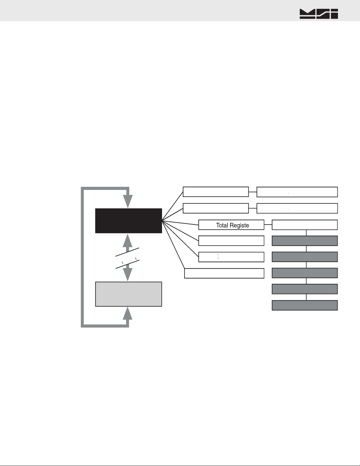
MEASUREMENT SYSTEMS INTERNATIONAL
Firmware Version 5-XX for 2450 Modems
SECTION 5 – ID CODES
• The CellScale can store 32 ID codes. The 9750A controls which ID Code is in use.
• Each ID Code stores a Tare Value, a Total Value, a weighment counter, display mode (Net, Gross, Peak, etc...),
Unit (lb., kg, ton, etc.), and two 20 byte ID code strings. Each ID code also computes and stores statistics of
Average, Min., Max., Standard Deviation, and Coeffi cient of Variance.
• ID Codes are created when a new name is entered by the user. The name can be all numbers, all letters, or a
combination of numerals and letters. Once the name is entered by the user, the CellScale scans its memory
to see if the ID Code already exists. If it does, all new totaled weighments are added to the previously totaled
weighments, and any preexisting Tare value will be used for NET weight computation. If the name did not
already exist, the CellScale creates a new ID Code.
• ID Codes are alphabetized when created using the standard ASCII convention.
• The 9750A uses the ID function key to scroll through all existing ID Codes as an alternate means of selecting
an existing ID code.
• The ID Strings are directly accessible by programming a Function key. The function key label can be custom-
ized on the LCD screen to indicate the usage of the string. Use the ID Strings for operator IDs, customer ID,
routing numbers, etc..
ID CODE ORGANIZATION
To
tal Counter
Total Register
Average Wt
Minimum Wt
Maximum Wt
Standard Deviation
Coef of Variance
To
To
tal Register
tal Register
tal Register
tal Register
ID CODE NAME
Up to 8 Characters
ID CODE NAME
Up to 8 Characters
are Register
Up to 32
32 ID Codes
Custom
ey
2
Char)
Custom F-K
ey
Label 1 (8 Char)
MSI CellScale® System • 9750A User Guide Page 27
Page 28
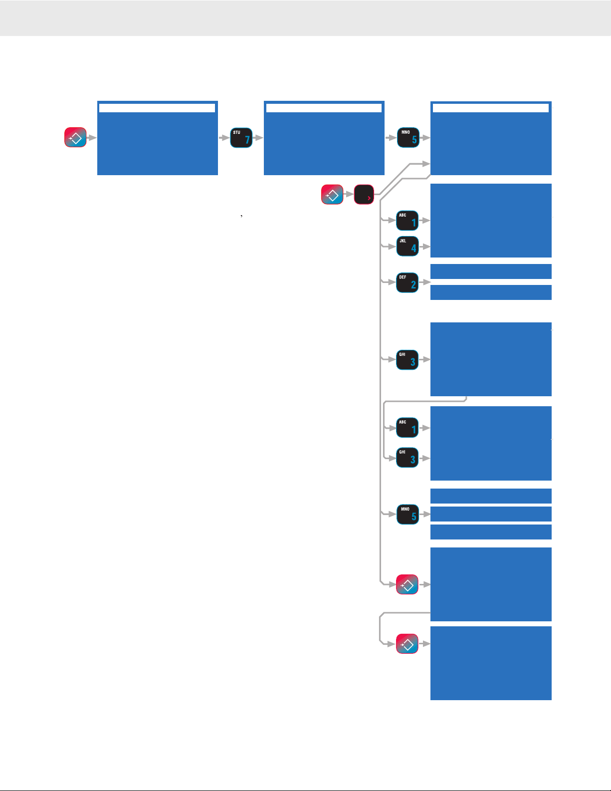
SETUP ID CODES MENU
Allows setup of ID Codes. A new ID can be created, the 8 character ID Name can be edited, two 20 character
print strings can be assigned to each ID Code. Also any or all IDs can be deleted from this menu.
SETUP SELECT MENU
1 Function Keys
2 Set Points
3 System
4 Password Locks
5 BarCode
6 Total
7 MORE 1/2
PRODUCT ID Chan X-X
Net XX ID IDName-1 New Product ID
2 ID Units kg
3 Edit ID Strings
4 Edit ID Name
5 Display Mode NORM
CLR Delete ID(s)
SETUP SELECT MENU
1 Channel & Calibrate
2 Scale Display Line
3 RF Modem
4 Comm 2 & Strings
5 Product ID Codes
6 Tare
7 MORE 2/2
Shortcut
Len 0 F4 Menu
Max 8 ENT Save
Pos 1
Prod ID Name
PRODUCT ID Chan X-X
Net XX ID IDName-1 Edit ID String 1
-ID String 12 Copy prev String 1
3 Edit ID String 2
-ID String 24 Copy prev String 2
2 ID Units kg
Len 0 F4 Menu
Max 20 ENT Save
Pos 1
ID String 1
2 ID Units lb
Steps through available units
(defined at CellScale)
1
1
Delete This ID
Are You Sure?
ENTER = Yes, Delete
ESC = No, Cancel
CLR = Delete All IDs
Delete All IDs
Are You Sure?
Deletes all Totals,
Stats,Names,Strings
ENTER = Delete All
ESC = No, Cancel
5 Display Mode NORM
5 Display Mode %
5 Display Mode OFF
SETUP SELECT MENU SETUP SELECT MENU PRODUCT ID Chan X-X
ZERO
CLR
0
ZERO
CLR
0
ESC
!
SETUP
ESC
!
SETUP
ID
F6
In the Product ID menus the
, and
keys are active. This allows you to setup IDs for all channels on
any programmed network without leaving the menu.
1) New Product ID – Calls a text enter screen for creating a new
ID. Use the alphanumeric keypad to enter any name up to 8
characters.
See “General Text Entry” for further information for text entry.
2) ID Units – Pressing
steps through the available units for
this channel and selects the units used for this ID
3) Edit ID Strings – Brings up a submenu for selection of ID
String 1 or 2.
4) Edit ID Name – Allows editing the 8 character ID name without
creating a new ID.
5) Display Mode – Should usually be left in the default condition
of “NORM”. Pressing
selects a per cent display mode (1%
resolution), or display ID disabled mode (OFF).
CLR
Delete ID(s) – Deletes current displayed ID (won’t delete ID1,
the default ID). Returns to channel default ID1 when fi nished.
Press
on the “Are You Sure?” screen to complete the
deletion. Any other key (except
) cancels the deletion.
From the “Are You Sure” screen, pressing
again will
allow you to “Delete All IDs” – Deletes every ID on the active
channel. Press
on the “Are You Sure?” screen to
complete the deletion. Any other key cancels the deletions.
1) Edit ID String 1 – Brings up a text entry screen. Enter or edit
up to 20 characters. The current ID string is shown below
selection 1.
2) Copy previous String 1 – Pressing 2 causes the last pro-
grammed String 1 to be copied into this IDs string 1. Use the
ID key or Channel key from this menu to activate other IDs
for the copy operation.
3) Edit ID String 2 – Brings up a text entry screen. Enter or edit
up to 20 characters. The current ID string is shown below
selection 3.
4) Copy previous String 2 – Pressing 2 causes the last pro-
grammed String 2 to be copied into this IDs string 2. Use the
ID key or Channel key from this menu to activate other IDs
for the copy operation.
HANDHELD RF REMOTE INDICATOR for CELLSCALE
®
ID, CHANNEL
[2]
[5]
ADDRESS
ENTER
ENTER
CLR
CLR
Page 28 MSI-9750A RF Remote Indicator • User Guide
Page 29

MEASUREMENT SYSTEMS INTERNATIONAL
Firmware Version 5-XX for 2450 Modems
To Create a New ID Code (Short method)
1) Press
, then
.
2) Using the numeric keypad enter a name for the new ID Code. Use the
key to select letters as
required.
To Create a New ID Code (Using the Setup ID menu)
1) Press
, then
or
, “MORE”
, then “Product ID Codes”
.
2) Select “New Product ID”
. This brings up a text entry screen.
3) Using the numeric keypad enter a name for the new ID Code. Use the
key to select letters as
required.
Press
. Each press of the ID key steps to the next programmed ID on this channel.
To Access an Existing ID Code (Scroll through available IDs)
To Access an Existing ID Code (fi nd existing ID)
see if the Code already exists.
1) Press
, then
.
2) Using the numeric keypad enter the name for the desired ID Code. Use the
key to select letters
as required.
To Access an existing ID Code (Using the Setup ID menu)
1) Press
, then
or
, “MORE”
, then “Product ID Codes” (
).
2) Select “New Product ID”
. This brings up a text entry screen.
3) Using the numeric keypad enter a name of an existing ID Code. Use the
key to select letters as
required. If the CellScale detects a match, the existing ID Code will appear. If not, it will create a new
one.
The 9750A maintains a default ID Code that functions identically to user entered ID Codes except that no name
is required. Any totals taken in the default ID Code are included in the grand total. The best way to recognize that
the default code is in operation is that it has no ID Code name. The default ID Code can be given a name using
“SETUP ID CODES”, but it will not be alphabetized, it will always be fi rst on the list.
To Scroll through Existing ID Codes
Press
. All ID codes will appear in order for the selected channel.
To Delete an ID Code
1) Using the
key, fi nd the ID Code you want to delete.
2) Press
, then
.
3) From the “PRODUCT ID” menu select “Delete ID”
.
4) From the “Are You Sure” screen press
to delete the ID. The Channel will revert to ID1 and the
previous ID is now gone. Cancel the delete operation by pressing
) or any key other than
.
ENTER
SETUP
ID [F6]
ENTER
ID [F6]
ID [F6]
[1]
ID [F6]
SETUP
[7]
ALPHA
[5]
ALPHA
ALPHA
SETUP
ID [F6]
SETUP
ENTER
ID
ID [F6]
[1]
ID [F6]
SETUP
ENTER
[7]
CLR
5
ALPHA
ESC (SETUP
MSI CellScale® System • 9750A User Guide Page 29
Page 30

stored in them.
To Delete all ID Codes
for all channels, you must select a channel using the CHANNEL key, then repeat this procedure for each Channel.
Memory Full
When all 32 product IDs have been fi lled, the system will report Memory Full.
1) Press
, then
.
2) From the “PRODUCT ID” menu select “Delete ID”
.
3) From the “Are You Sure” screen press
to delete the all the product ID. The Channel will revert to
ID1 (default ID) and all other IDs are now gone. Cancel the delete operation by pressing
(Setup) or
any key other than
or
.
ID CODE STRING 1 & STRING 2
Each ID code can be further identifi ed with one or two ID Code Strings. A string is simply a set of alphanumeric
characters that can be displayed and/or printed. Each string can be up to 20 characters in length. The MSI “@
codes” can also be embedded in the string which provides an extremely versatile output capability. With @codes
the result of the 20 character ID string may be greatly expanded. Also ID strings can be embedded in the main
print string to combine them with other data. See Section 7 – Comm Ports, for more details on programming “@
codes”.
Use the ID Code Strings to set up a print string that changes with every ID code. Combined with the standard
Comm Port print strings, the ID strings can be used to design a very sophisticated bar code label with three fi elds
that change with every ID Code – the ID Code Name, and ID String 1 and 2.
The Function keys can be programmed to allow one button access to 1 or both ID Strings. This can be used for
Operator ID entry, or direct access to the label printer data when the ID string is embedded in the main Comm Port
output. Programming a function key for ID String 1 or ID String 2 also allows a text entry to identify the string.
For example, you could Label the key for ID String 1 “Operator” and ID String 2 “Customer”. Then by enabling
the function key labels, a clear identifi cation of what the strings are for is on the LCD screen.
To Add or Edit an ID Code String
Select the ID Code you wish using the procedure "To Access an Existing ID Code" (previous page)
1) Press
, then
or
, “MORE”
, then “Product ID Codes”
.
2) Select “Edit ID Strings”
.
3) Select “Edit ID String 1” (or 2). This brings up a text entry screen.
4) Using the numeric keypad enter the ID string (up to 20 characters). Use the
key to select letters
as required.
entered.
To Access the ID Code Strings with the FUNCTION keys
For this procedure to function, a FUNCTION key must be programmed for “Product ID String 1” and/or “String 2”. The key(s) used for this purpose can be labeled
to suit your needs (e.g. “CUSTOMER” or ‘OPERATOR”, etc.) See Section 4– FUNCTION KEY PROGRAMMING for details.
1) Press the Function key assigned to the ID string. This brings up a text entry screen.
2) Using the numeric keypad enter the ID string (up to 20 characters). Use the
key to select upper
case or lower case letters as required.
HANDHELD RF REMOTE INDICATOR for CELLSCALE
®
SETUP
ID [F6]
ENTER
CLR
CLR
ESC
CLR
SETUP
Page 30 MSI-9750A RF Remote Indicator • User Guide
ID [F6]
[3]
SETUP
[7]
[5]
ALPHA
ALPHA
Page 31

MEASUREMENT SYSTEMS INTERNATIONAL
Firmware Version 5-XX for 2450 Modems
SECTION 6 – TOTAL / STATISTICS
TOTAL
• The 9750A can add independent weighments together and keep a counter of how many weighments were
added (Totaled). The Weighments counter can be thought of as a box or palette counter.
• “TOTAL” always uses the displayed weight, so gross and net readings can be added into the same total.
• There are two modes of Totaling which are set in the SETUP TOTAL section. The Manual mode uses the
key to add the current weight to the previously totaled value. The Auto mode will automatically add
the last, settled value to the total (or optionally the highest value). See “SETUP TOTAL” for instructions to
enable the AUTO TOTAL modes.
• Both modes have a means to prevent the same load from totaling twice. Once totaled, the load must be
removed from the scale before a new load can be added to the Total. Applied weight must be greater than
the Total Threshold before it can be totaled. See “SETUP TOTAL” for instructions on how to set the Total
Threshold.
To Total with the
Key
(Unit must be setup to Manual Total mode)
Rules for use:
menu.
2) Only readings above the High Threshold can be accumulated.
3) The scale adds the current reading (relative to the Net zero or Gross zero depending on mode) to the contents
of the accumulate register.
4) After a weighment is totaled, the weight must go below the Total Threshold before another weight can be
added to the total. This assures that a weight on the scale is only added to the total once.
AUTO TOTAL
SETUP Option, see “SETUP TOTAL” to enable Auto Total.
When the weight exceeds the Total Threshold the total function operates automatically.
There are 5 modes of Auto Total. Each mode is used in slightly different ways.
Mode 1, Autonorm: The displayed weight is held in a holding register and added when the weight returns below
the Total Threshold. The last settled reading is what will be used for totaling when the scale returns below the
Total Threshold. The user must make sure that while removing the load the scale does not stabilize enough for
a new reading or an erroneous weighment addition could occur. The last settled weight is actually added to the
total when the scale returns to below the Total Threshold.
Mode 2, Autopeak: The “AUTOPEAK” total mode works the same as Autonorm, except that the highest settled
reading will be used for totaling on return to zero, rather than the last settled reading.
Mode 3, Autoload: totals the applied weight as soon as the weight is stable (Motion Indicator off). Additional
weight cannot be totaled until the weight drops below the Total Threshold
Mode 4, Loaddrop: After pressing the
key, the CellScale starts a long term, motion compensated (if the
motion compensation option is installed in the CellScale), average of the current weight that ends when the weight
is dropped. This method is designed for commodity weighing of scrap metal, or other types of materials that are
loaded into rail cars, trucks, hoppers, etc., usually with a crane.
Place the weight to be totaled on the scale. When the weight has stabilized, press the
Key
.
The current weight is added to the total register. If the display is setup to display the total, the display gives
an indication of how many weighments have been totaled. i.e. 6 #. There may be a small delay before the
CellScale reports back to the 9750A the new Total and Total weighments.
is removed (weight drops below the total threshold). When combining print modes with
modes if an immediate current weight and totaled weight printout is required.
Mode 5, Onaccept: In conjunction with target weights set up in the set points menus, the Onaccept total mode
will automatically total settled readings that fall within the preselected accept weight window. See Section 8 “Set
Points” for information on setting accept limits.
TOTAL
TOTAL
TOTAL
[F1]
TOTAL
MSI CellScale® System • 9750A User Guide Page 31
Page 32

Auto Total Operation
“AUTONORM”, “AUTOLOAD”, or the “AUTOPEAK” mode. Exit from the setup menu.
2) Use the
key to disable (“TTL OFF”) or enable (“TTL ON”) Auto Total.
3) Place the weight to be totaled on the scale.
4) Remove the weight. The screen will read “TOTALING” briefl y, then return to the weight display.
the total. Turning the Auto Total off does not erase the current total. See “To Clear the Total Value” to learn how to erase the Total.
Rules for Auto Total:
2) Weight readings must be greater than the set High Total Threshold.
3) Each reading added to total must be preceded by a return to net or gross zero (below the Low Total Thresh-
old).
SETUP TOTAL MENU
Allows setting Totalizing parameters.
SETUP SELECT MENU
1 Function Keys
2 Set Points
3 System
4 Password Locks
5 Display Preview
6 Total
7 MORE 1/2
TOTAL MODE
1 Disabled
2 Auto Load
3 Auto Norm
4 Auto Peak
5 On Accept
6 Manual
7 Load Drop
TOTAL SETTINGS
--Chan Name--
1 Mode DISABLED
2 Motion Check ON
3 High Threshold 11%
4 Low Threshold 10%
HIGH TOTAL THRESHOLD
ESC exits no change
ENTER saves value
0-9 replaces value
1Ø
min = 1, max = 100
^ incs, v decs value
LOW TOTAL THRESHOLD
ESC exits no change
ENTER saves value
0-9 replaces value
5
min = 0, max = 99
^ incs, v decs value
2 Motion Check ON
2 Motion Check OFF
SETUP SELECT MENU TOTAL SETTINGS
TOTAL MODE
HIGH TOTAL THRESHOLD
LOW TOTAL THRESHOLD
or
ESC
!
SETUP
F1
TOTAL
6
PQR
2
DEF
1
ABC
3
GHI
4
JKL
TOTAL MODE – The Manual mode requires
that the
key is pressed when the weight
currently on the scale should be added to the
previously accumulated value. See description
on previous page of the 7 total modes.
TOTAL MOTION – Enables or disables Motion
Detection for Manual Total. Has no effect on
AUTOTOTAL. This menu item controls whether
the scale has to be out of motion before it will
total. In certain high vibration applications it is
sometimes desirable to turn off the motion detect
so that Totalizing can occur. This feature is dis-
abled for legal-for-trade systems.
HIGH TOTAL THRESHOLD –
LOW TOTAL THRESHOLD –
Sets the weight value above which Totalizing is
allowed. For example, setting the high threshold
to 10% on a 200 kg scale will set the threshold at
20 kg. Only weight above 20 kg will add to the
Total. Once totaled, the weight must return below
the Low Threshold to enable the next totalizing.
This prevents the same weight from being totaled
twice. Another example: On a scale with a capac-
ity of 1000 kg the user desires to Auto Total all
weight that exceeds 50 kg. Since 50 kg is 5% of
Threshold is entered in 1% increments.
Minimum Thresholds are 1% for the high, and 0% for the low.
HANDHELD RF REMOTE INDICATOR for CELLSCALE
TOTAL
®
[1]
TOTAL
[2]
[3]
[4]
Page 32 MSI-9750A RF Remote Indicator • User Guide
Page 33

MEASUREMENT SYSTEMS INTERNATIONAL
Firmware Version 5-XX for 2450 Modems
To Set the Total Mode
To Turn On or Off Auto Total
1) Press
.
2) Press the
switch
or select
Total.
3) The current Total Mode is shown on selection 1.
4) Press the
key to bring up the “Total Mode Selection” menu.
5) Select the desired Total Mode with the numeric keys (
). You are returned to the “Total Status” with the
new mode indicated on selection 1.
6) Motion Setting – If totals are allowed before the scale settles, disable Motion by pressing
. Disabling
Motion should only be used in situations where the weight may never settle. Accuracy will suffer.
Some AutoTotal modes require no motion to function (Auto Load, Auto Norm) and will ignore the setting here. ON means totals will not function until the
7) Press the
key to return to normal scale operation or the
key to continue in the Setup Menus.
Auto Total is now enabled.
Turn on or off Auto Totaling by pressing the
key
. The display will read “TOTAL ON” along
with the current total mode, or “TOTAL OFF”.
To Set the Total Threshold
VIEW TOTAL
Displays the current Total value of the selected ID and allows the total(s) to be cleared.
by pressing the CHANNEL key. You can change to the next ID by pressing the ID key.
To Display the Current ID#’s Totaled Weight and Statistics
1) Press
.
2) Press the
switch
or select
Total.
3) Select “High Threshold” by pressing
.
4) Enter the desired high threshold with the numeric keys. Threshold is expressed in per cent of capacity.
5) Set the new high threshold by pressing
.
If the high threshold you entered was lower than the previous low threshold, the CellScale automatically adjusts the low threshold to be 1% less than
the high threshold.
6) To change the low threshold, press the
key.
7) Enter the desired low threshold with the numeric keys.
8) Set the new low threshold by pressing
.
If the low threshold you entered was higher than the previous high threshold, the CellScale automatically adjusts the high threshold to be 1% more than
the low threshold.
9) Press the
key to return to normal scale operation.
1) Press
. The current IDs total appears on line two, the number of
totaled samples on line three, and the ID name (if programmed) on line
2) To return to the standard weight display, press
or
.
1) Press
. The current total is displayed.
2) Select “Clr Last” by pressing
. The “ARE YOU SURE” screen gives an opportunity to change your
mind.
3) To complete the last totaled weight deletion, press the
key.
To Erase the last Totaled Weight
If the last totaled (automatic or manual) weighment was a mistake, it can be erased with the following procedure. This erases only the last totaled weighment.
SETUP
TOTAL
[1]
EXIT
SETUP
TOTAL
[F1]
[F1]
[3]
[6]
[6]
TOTAL
1
7
[2]
ESC
[F1]
[F5]
EXIT
ENTER
[4]
ENTER
DISPLAY
ESC
ID NAME ID# CH#
1000.5lb ∑
6 #
1 Grand 3 Clr Last
2 Stats CLR Delete
VIEW ∑
[3]
ENTER
MSI CellScale® System • 9750A User Guide Page 33
Page 34

To Clear the Total Value (Current ID Code only)
At any time during the following procedure the
key cancels the Clear operation. Clears ID’s statistics registers as well.
1) Press
. The current total is displayed.
2) Press
. The “ARE YOU SURE” screen gives an opportunity to change your mind.
3) To complete the totaled weight deletion, press the
key.
To Clear All the Totals and Statistics of all ID Codes at once.
1) Press
. The current total is displayed.
2) Select “Grand” total by pressing
.
3) Press
. The “ARE YOU SURE” screen gives an opportunity to change your mind.
4) To complete the totaled weight deletion of all current channel ID Codes, press the
key.
Clear Last Total
The “Clear Last Total” function key (see Section 4) provides a means to clear just the last totaled data without
clearing the entire total register. Use this when a weight is totaled inadvertently or a load drops outside the con-
tainer, or any other circumstance where just the last total should be deleted from the overall total. “Clear Last
Total” is the default mode for
.
STATISTICS
Statistics works in conjunction with the Total function and adds MIN, MAX, Average, Standard Deviation, and
Coeffi cient of Variance. All these computations are kept for every ID Code independently. The number of samples
that statistics can be calculated for is limited only by memory requirements and will vary from a few thousand to
>100000 samples. Individual samples are not stored. If needed, individual samples can be logged through either
the RS-232 port or into data logging memory using the “PRINT on TOTAL” function.
A “GRAND TOTAL” function is also included with the Statistics function. The Grand Total adds all the weight
in all the ID Codes and provides the following information: GRAND TOTAL, Number of Totals, and the Overall
Average (GRAND TOTAL divided by Number of Totals).
Statistics are viewed using the
key, then selecting “STATS” with the
key, or program a func-
tion key to “Show Statistics” .
AVERAGE – is computed by dividing the total by the number of samples.
MIN – is a single weight register that records the minimum weighment that was added to the total.
MAX– is a single weight register that records the maximum weighment that was added to the total.
STANDARD DEVIATION – is a measure of how widely values are dispersed from the average value (the
mean). The 9750A uses the “non-biased” or “n-1” method that is based on sampling a portion of each available
weighment. Standard Deviation uses the following formula where x is equal to the total, and n is equal to the
number of samples:
COEFFICIENT OF VARIANCE – is a relative dispersion calculated from the sample standard deviation and the
mean with the following formula:
GRAND TOTAL – is computed by adding together the totals of all the ID Codes (adjusted to the default unit set
in calibration if necessary).
GRAND AVERAGE – is computed by dividing the Grand Total by the number of samples of all the ID Codes.
VIEW ∑
CLR
VIEW ∑
CLR
HANDHELD RF REMOTE INDICATOR for CELLSCALE
EXIT
®
ENTER
[1]
ENTER
ENTER
[F1]
VIEW TOTAL
[2]
Page 34 MSI-9750A RF Remote Indicator • User Guide
Page 35

MEASUREMENT SYSTEMS INTERNATIONAL
Firmware Version 5-XX for 2450 Modems
1) Press
. The current IDs total appears on the top line, the number
of totaled samples on line 2, and the ID name (if programmed) on line
3.
2) To see the statistics for the current ID, select “Stats” by pressing
.
When in the Statistics display, return to the Total display by press-
ing
, or return to the standard weight display by pressing
.
3) To see the grand total and statistics for all IDs on this scale channel,
select “Grand” by pressing
. When in the Grand Statistics display,
return to the Total display by pressing
, or return to the standard
weight display by pressing
.
4) To return to the standard weight display, press
.
View Statistics and Grand Statistics
The View Statistics feature uses totaled data from the current ID code in the CellScale to compute statistics.
Grand Statistics uses totaled data from all ID codes. Only weight that has been totaled will be used in computing
statistics. This procedure requires that F5 is programmed as “VIEW TOTAL”.
ESC
PLAY
[F5]
[1]
DISPLAY
ESC
DISPLAY
[2]
DIS-
ID NAME ID# CH#
1000.5lb ∑
6 #
1 Grand 3 Clr Last
2 Stats CLR Delete
ID Name ID# X-X NET
-Total----- ∑
-#Samples- #
-Minimum- MIN
-Maximum- MAX
-Average- AVG
-Std Dev- SDV
-CoefofVar- CoV
ID Name ID# X-X NET
-Grand Total- ∑
-#Samples- #
-GrandMin- GMN
-GrandMax- GMX
-GrandAvg- GAV
-GrandStdDev- GSD
-Grand COV- GCV
MSI CellScale® System • 9750A User Guide Page 35
Page 36

5 Daylite Saving OFF
5 Daylite Saving ON
SYSTEM SETTINGS
CS SW Version: 2-24
1 Key Volume is 1
2 Alarm Volume is 9
3 Backlight on 2min
4 Date & Time
5 Auto Shutdown 2hr
6 Monitor Batteries
BACKLIGHT
1 Off (max bat-life)
2 On for 15 seconds
3 On for 30 seconds
4 On for 1 minute
5 On for 2 minutes
6 Always On (reduces
battery life)
SET DATE & TIME
9/15/03 1:24:33 PM
1 Set Date
2 Set Time
3 Date Mode MM/DD/YY
4 Time Mode AM/PM
5 Daylite Saving ON
4 Time Mode 24 Hr
4 Time Mode AM/PM
3 Date Mode DD-MM-YY
3 Date Mode MM/DD/YY
5 DayliteSaving AUTO
AUTOMATIC SHUTDOWN
1 Off in 5 minutes
2 Off in 30 minutes
3 Off in 1 hour
4 Off in 2 hours
5 Always On
MONITOR BATTERIES
Main = 7.2V
Clock & RAM = GOOD
CellScale XX = GOOD
Cal. Voltage = 1.24
V
Temperature is 33°C
KEYPRESS VOLUME = 1
1
z
2
n
3
nz
4
nn
8
nnnn
5 nnz
9 nnnnz
6
nnn
0
nnnnn
7 nnnz
CLR Off
ALARM VOLUME = 8
1 z
2 n
3 nz
4 nn
8 nnnn
5 nnz
9 nnnnz
6 nnn 0 nnnnn
7
nnnz
CLR Off
SETUP SELECT MENU
1 Function Keys
2 Set Points
3 System
4 Password Locks
5 Display Preview
6 Total
7 MORE 1/2
SETUP SELECT MENU SYSTEM SETTINGS KEYPRESS VOLUME = 1
5
MNO
5
MNO
ALARM VOLUME = 8
BACKLIGHT
SET DATE & TIME
AUTOMATIC SHUTDOWN
MONITOR BATTERIES
ESC
!
SETU
P
POWER
4
JKL
ESC
!
SETUP
3
GHI
4
JKL
3
GHI
2
DEF
1
ABC
6
PQR
3
GHI
SECTION 7 – 9750A SETUP
SYSTEM SETUP MENU
Allows the user to set the key and alarm volumes, the display back-
light timing, the Time and Date, and the automatic shutdown timing.
The battery monitor screen is also accessible from this menu.
Access the System Setup Menu by pressing
followed
by the
key.
Key Volume is X – In the submenu, change the volume
heard when pressing keys with keypad numbers 1 (quiet)
through 0 (loud). To turn off the key tones, press
.
Alarm Volume is X – Change the volume heard when a
set point is triggered. Also used for data logging alerts.
See
section 8 for details on audible set point outputs.
Backlight on X – Submenu selects how long the backlight
will remain on. This value is re triggered whenever a key
is pressed. Directly effects battery life (time between
charges). Do not select “Always On” if battery life is a
concern.
Date & Time – See submenu description below.
Auto Shutdown – Select the time the 9750A will wait
before turning off. This time is re triggered any time a key
is pressed.
Monitor Batteries – The monitor battery screen shows the
status of system batteries. The NiMH main battery will
vary from as high as 9.0V with the charger plugged in to
as low as 6.0V right before the system is cut off. The fl at
region of the battery will average 7.4 to 7.6V during normal
operation. The internal clock battery should last for many
years. When this display indicates “BAD” for the clock
battery, it must be replaced. This requires a disassembly
of the 9750A. If a CellScale is connected via RF, it will
also report its power status here.
A shortcut to the Monitor Batteries screen is
fol-
lowed by
.
SET DATE & TIME (submenu)
tions must be set independently.
From the “System Setup Menu” select
.
Set Date – Enter the date with the numeric keypad. The
date entry order is set by item 3.
Set Time – Enter the current time with the keypad. The
time entry mode is set by item 4. When in AM/PM mode
use either the
cursor keys to change AM to
PM or PM to AM, or use the
key for AM or the
key for PM.
mode before setting the date and time.
HANDHELD RF REMOTE INDICATOR for CELLSCALE
®
SYSTEM
[3]
[1]
CLR
[2]
[3]
[4]
[5]
[6]
POWER
[1]
[2]
UP/DOWN
ABC1
PQR6
Page 36 MSI-9750A RF Remote Indicator • User Guide
SETUP
4
Page 37

MEASUREMENT SYSTEMS INTERNATIONAL
Firmware Version 5-XX for 2450 Modems
The Lock function allows the user to lock various setups and or functions to prevent unauthorized changing or
erasing of scale functions, features and statistical data. For security a lock password (1-14 characters) is used. Once
the MSI 9750A is locked the message “LOCKED” will appear whenever a locked function is tried. To temporarily
unlock a function, press any locked key, press
, then enter the password followed by the
key.
To lock or unlock all functions you must use the “PASSWORD LOCKS” menu.
SETUP SELECT MENU
1 Function Keys
2 Set Points
3 System
4 Password Locks
5 BarCode
6 Total
7 MORE 1/2
PASSWORD LOCKS
1 Change Password
2 Status LOCKED
3 Lock Mode
4 Lock Override OFF
Password is:
-Password-
LOCK MODE
1 Function Key Setup
2 Set Points
3 System Settings
4 Set Password Locks
5 Display Preview
6 Total Setup
7 MORE 8 BACK 2/3
LOCK MODE
1 Channel/Calibrate
2 Scale Display Line
3 RF Modem
4 Comm 1 & Strings
5 Product ID Codes
6 Tare Setup
7 MORE 8 BACK 3/3
LOCK MODE
1 Lock All
2 FUNCTION Keys
3 SETUP Key
4 TARE Key
5 NET/GROSS Key
6 ZERO Key
7 MORE 8 BACK 1/3
2 Status LOCKED
2 Status UNLOCKED
7
7
7
8
8
8
2 Status LOCK ON PWR
Len 0 F4 Menu
Max 14 ENT Save
Pos 1
NEW PASSWORD
1
SETUP SELECT MENU PASSWORD LOCKS
LOCK MODE
LOCK MODE
LOCK MODE
4 Lock Override OFF
4 Lock Override ON
See General Text Editing
Procedure
ESC
!
SETUP
To enter the Password Locks Menu press
then [
.
Change Password – Used to change the password. Pressing
brings up a text entry screen. Use the
key and the
keypad to input any password. Passwords are case sensitive,
so pay attention to upper and lower case characters.
Status – Pressing the
key changes the status from
“LOCKED” to “UNLOCKED” to “LOCK ON PWR”. The
“LOCK ON PWR” mode leaves the 9750A unlocked until the
power has been cycled. This allows the primary operator to
complete all setups without having to enter the password over
and over. When completely fi nished with setups, cycle the
power and then the lock will be in effect.
Do not forget your password. The only way to unlock a
locked system without the proper password is to do a
complete reset (RESET ALL), which will cause you to lose
all setups. Make a note of it in a secure location.
Lock Mode – Press the
key to select features and functions
for password protection. There are 3 submenu select screens. Use
the
key to scroll through all lockable items. Press the number
key beside each item to select it for locking. For example, to
lock out the Setup key press
. The arrow will appear indicat-
ing the Setup Key will lock. After selecting all the lock items,
press
to return to the “PASSWORD LOCKS” menu.
functions while in the Lock Mode menu.
MSI provides a master unlock that will erase all operator setups and
require you to completely start from scratch. This procedure will not
erase calibration, which is stored in the CellScale, not the 9750A.
However, all display modes, text strings, system settings, etc., stored
in the 9750A, will be lost.
Date Mode – Pressing
changes the date mode from MM/DD/YY to DD-MM-YY.
Time Mode – Press
to change between 24 hour time or 12 hour time with AM/PM indication.
Daylite (sic) Saving – Press
to select the Daylight Saving mode. Select “ON” when in Daylight Savings
Time (adds 1 hour). Select “OFF” when not in Daylight Savings time. Select “AUTO” to allow the 9750A
to automatically enter into and out of daylight savings time (follows US rules). Set the daylight saving
mode before setting the date and time.
[3]
[4]
[5]
[1]
[1]
[4]
[3]
[5]
ENTER
SETUP
ALPHA
ENTER
4]
[2]
[3]
[7]
SETUP
[2]
[3]
[3]
MSI CellScale® System • 9750A User Guide Page 37
Page 38

Keyboard lock is provided to prevent casual or accidental pressing of the keys from changing any modes. This
function works only from weight display modes.
1) Press
followed immediately by
). The startup screen will appear.
2) Press the
) key. A password text entry screen will appear.
3) Using the keypad, input the number 7415369. Press
.
4) The “ARE YOU SURE” display appears. Press
.
Everything is reverted to defaults. Now you must setup the 9750A again.
RESET ALL: The following procedure will cause you to lose all setups and will return
lost
your password.
To Lock the Keyboard
The 9750A offers the user a great deal of fl exibility in how weight and other information is displayed. There are
fi ve single channel preset displays and fi ve multiple channel preset displays. These presets cover the majority of
user applications. However, the 9750A also allows complete customizing of how scale data is presented on the
display.
There are two basic weight display modes, Single Channel, and Multiple Channel. The single channel display is
the primary weight display, and is used as the display mode when a channel is highlighted and switched out of
the multiple channel display. If your CellScale is equipped with multiple channels, the display can be set up to
show up to eight channels at once.
When setting up Weight Displays, the 9750A shows a preview of how the screen will be formatted. Abbrevia-
tions for preview screens indicate what kind of data will be presented in each screen location. Dashes are used to
indicate the maximum screen space the data will occupy.
Weight
................
Current Weight in Net or Gross with Units, Motion, and Center of Zero (COZ) indicators.
Gross-Wt
...........
Gross Weight only
Tare-Wt
..............
Tare Weight only
CHN
..................
Channel number in the form X-X. e.g. 1-1. The Channel number is determined by the CellScale
Scan List.
.................
Network Address in the form of XXA. e.g. 17A
Ch-Name
............
Channel Name. The Channel Name is programmed in the CellScale.
DateTime
............
Shows the Date and Time. When in the form “DateTimeEnter-Number” it may be overwritten
when entering a number with the keypad.
Enter-Number
.....
Field accepts keypad entry for assignment to various functions.
.........
Show ID string 1.
2-ID-String
.........
Show ID string 2.
Total-Wt-ID
........
Shows the Total weight stored in the current ID Code.
#-SamplesI
.........
Shows the number of samples totaled and used for statistics for the current ID Code.
IDC
.....................
The ID Code number in the form xxI. e.g. 2I is ID Code 2.
IDName--
...........
The ID Code name. The name must be programmed by either the CellScale or the 9750A.
Press
. The screen will read “KEYBOARD LOCKED” briefl y.
To Unlock the Keyboard
Press
. The screen will read “KEYBOARD UNLOCKED” briefl y.
Now all keys should function normally.
HANDHELD RF REMOTE INDICATOR for CELLSCALE
POWER
CLR (ZERO
[1] [2] [3] ALPHA
[1] [2] [3]
ESC (SETUP
®
ENTER
ENTER
Page 38 MSI-9750A RF Remote Indicator • User Guide
Page 39

MEASUREMENT SYSTEMS INTERNATIONAL
Firmware Version 5-XX for 2450 Modems
-Weight-
CHN ADR
Ch-Name------------1-ID-String--------DateTime-Enter-Num.
Standard Weight – Lines 1-4: Large Current Weight display (-Weight-). Line 5: Chan-
nel Number, and the Network Address. Line 6: the Channel Name (if programmed in the
CellScale). Line 7: ID String 1 (if entered at the CellScale or by the 9750A functions). Line 8:
The Date and Time. When entering numbers, the Time display will be overwritten temporarily.
xS or xSL
............
The Scan List Index position as stored in the CellScale where x is 1-8. Used on multiple display
presets to show which scan list position is included on the preset display. These can be later
altered to any scan list position 1-32.
SLI
......................
Scan List Index position displayed in the form xSL (positions 1-9) or xxS (positions 10-32).
x’s-Weight
..........
Current weight from scan list position x.
x’s-Ch-Name
......
Channel name from scan list position x. Channel names are programmed at the CellScale.
x’s IdNm
.............
ID Code Name from scan list position x.
Single Channel Preset Displays
The 9750A utilizes a programmable full dot matrix display capable of multiple font sizes. The smallest font is
a 5x7 dot count in a 6x8 cell yielding a maximum character count of 20 characters in 8 lines. The medium font
is a 7x15 in a 8x16 cell which provides up to 4 lines of 16 characters. The large font allows up to two lines of 8
characters. When the weight is displayed in the large font, smaller characters for units, Net/Gross mode, COZ,
and motion allow the large font to contain all necessary weight data. In the following preset display descriptions
the data is located by lines 1-8 relative to the smallest font.
Standard & Products – This display shows ID Code data for Totalizing. Lines 1-4: Large
weight display (-Weight-). Line 5: shows the ID Name and ID Code number. Line 6: the total
weight and the Network Address. Line 7: shows the number of samples in the Total and the
channel number. Line 8: the Date and Time. When entering numbers, the Time display will be
overwritten temporarily.
Net Gross Tare – For applications that need to see the Net weight, Gross weight, and Tare
weight simultaneously. Lines 1-4: Large Net Weight display (-Weight-). Line 5: Gross Weight
and the Channel number. Line 6: The Tare Weight and the network address. Line 7: the Chan-
nel Name (if programmed in the CellScale). Line 8: the Date and Time. When entering num-
bers, the Time display will be overwritten temporarily.
If no Tare value is set the Net weight and Gross weight will equal each other. While in this display the Net/Gross key will have no effect
since both Net and Gross Weight are already shown. However, pressing the Net/Gross key will change the display mode for other devices
connected to the master CellScale.
Standard & Strings – This display shows ID Code Strings for user data entry. Lines 1-4: Large
weight display (-Weight-). Line 5: shows the ID Name and ID Code number. Line 6: the total
weight and the Network Address. Line 7: shows the number of samples in the Total and the
channel number. Line 8: the Date and Time. When entering numbers, the Time display will be
overwritten temporarily.
Maximum Data – This display shows all standard data available for any given scale channel
and associated ID. Line 1: Net Weight and Scan List Index. Line 2: Gross Weight and Chan-
nel Number. Line 3: Tare weight and Network Address. Line 4: the Total Weight and the ID
number (1-32). Line 5: number of totaled samples and the 8 character ID name. Line 6: ID
String 1. Line 7: ID String 2. Line 8: the Date and Time. When entering numbers, the Time
display will be overwritten temporarily.
-Weight------- SLI
Gross-Wt--- CHN
Tare-Wt---- ADR
Total-Wt-ID---- IDC
#-SamplesI IdName-1-ID-String--------2-ID-String--------DateTime-Enter-Num.
-Weight-
Gross-Wt--- CHN
Tare-Wt---- ADR
Ch-Name------------DateTime-Enter-Num.
-Weight-
IDName-- IDC
Total-Wt-ID---- ADR
#-SamplesI CHN
DateTime-Enter-Num.
-Weight-
CHN IdName-- ADR
1-ID-String--------2-ID-String--------DateTime-Enter-Num.
MSI CellScale® System • 9750A User Guide Page 39
Page 40

Multi-channel presets use the scan list position to assign channels to specifi c locations. After selecting the preset
multi-channel display, the user can reassign any channel in the scan list to any screen location.
The Multi-Channel Preset Displays are described by line numbers 1-8 corresponding to the small font layout. The
®
®
numbers in the sample screens and descriptions correspond to the scan list position index (SLI).
The 9750A reads the scan list out of the master CellScale. If a multi-channel preset is selected that allows more
channels than the CellScale has in its scan list, the preset will show just the available channels. If space allows
the Date and Time will appear on the bottom line (Line 8).
3 Ch -1 lg, 2 sm – This display is primarily intended for summing where scan list positions
However, any type of channel list can be used with this display and the list order can be
changed after this preset is selected. Lines 1-4: SLI 3 large current weight display (-Weight-).
Line 5: SLI 1 Current Weight and Network address. Line 6: SLI 1 Channel Name (if pro-
grammed in the CellScale). Line 7: SLI 2 Current Weight. Line 8: SLI 2 Channel Name.
4 Ch - 4 sm + data – This display shows four channels along with each channels Channel
Name. The Channel name must be programmed into the CellScale for it to appear. If less than
four channels exist in the scan list, the bottom channel will be replaced with the date/time/enter
number line. Line 1: SLI 1 Current Weight preceded by the scan list number. Line 2: SLI 1
Channel Name. SLI 2-4 follow the same format.
2 Ch -2 med+ data – This display shows two channels along with each channels 8 character ID
Name and 20 character ID String 1. Lines 1-2: SLI 1 Current Weight preceded by the scan list
number. Line 3: SLI 1 Channel Number (e.g. 1-1), SLI 1 ID Name, and the Network Address.
Line 4: SLI 1 ID String 1. Line 5-6: SLI 2 Current Weight preceded by the scan list number.
Line 7: SLI 2 Channel Number (e.g. 2-1), SLI 2 ID Name. Line 8: SLI 2 ID String 1.
4 Ch - 4 med – Displays 4 channels in the 9750A medium size font. The weight data is pre-
ceded by the scan list position index number (1-32). If less than four channels exist in the scan
list, the bottom channel will be replaced with the date/time/enter number line. Lines 1-2: SLI 1
Current Weight preceded by the scan list number. Lines 3-4: SLI 2 Current Weight preceded by
the scan list number. Lines 5-6: SLI 3 Current Weight preceded by the scan list number. Lines
7-8: SLI 1 Current Weight preceded by the scan list number.
8 Ch - 8 small – Maximum channel count display of up to eight channels. Each channel is pre-
ceded by the scan list position index number (1-32). If less than eight channels exist in the scan
list, the bottom channel will be replaced with the date/time/enter number line.
3’s-Wei
g
1’s-Weight---- ADR
1’s-Ch-Name--------2’s-Weight---2’s-Ch-Name---------
1S 1’s-Weight----
1Ch 1’s-IdNm ADR
1’s-1-ID-String-----
2S 2’s-Weight----
2Ch 2’s-IdNm
2’s-1-ID-String-----
1SL 1’s-Weight---1’s-Ch-Name--------2SL 2’s-Weight---2’s-Ch-Name--------3SL 3’s-Weight---3’s-Ch-Name--------4SL 4’s-Weight---4’s-Ch-Name---------
1S 1’s-Weight---2S 2’s-Weight---3S 3’s-Weight---4S 4’s-Weight----
1SL 1’s-Weight---2SL 2’s-Weight---3SL 3’s-Weight---4SL 4’s-Weight---5SL 5’s-Weight---6SL 6’s-Weight---7SL 7’s-Weight---8SL 8’s-Weight----
DISPLAY SETUP MENU
The Display Setup Menu provides access to all the display presets, backlight control, function key displays and
full display customizing.
To Enter the Scale Display Setup Menu
1) Press
. The main Setup Screen appears.
2) Press the
key.
The following describes the various menu item functions and covers the preset single and multi-channel display
modes.
HANDHELD RF REMOTE INDICATOR for CELLSCALE
®
SETUP
Page 40 MSI-9750A RF Remote Indicator • User Guide
DISPLAY
Page 41

MEASUREMENT SYSTEMS INTERNATIONAL
Firmware Version 5-XX for 2450 Modems
SCALE DISPLAY SETUP
1 Single Scale Mode
2 Multi Scale Mode
3 Backlight 2min
4 Backlight Level 3
5 Contrast 16
6 Tp Compensation 0
6 Tp Comp START 35°C
3’s-Wei
g
1’s-Weight---- ADR
1’s-Ch-Name--------2’s-Weight---2’s-Ch-Name---------
1S 1’s-Weight----
1Ch 1’s-IdNm ADR
1’s-1-ID-String-----
2S 2’s-Weight----
2Ch 2’s-IdNm
2’s-1-ID-String-----
-Weight-
CHN ADR
Ch-Name------------1-ID-String--------DateTime-Enter-Num.
-Weight-
Gross-Wt--- CHN
Tare-Wt---- ADR
Ch-Name------------DateTime-Enter-Num.
-Weight-
IDName-- IDC
Total-Wt-ID---- ADR
#-SamplesI CHN
DateTime-Enter-Num.
-Weight------- SLI
Gross-Wt--- CHN
Tare-Wt---- ADR
Total-Wt-ID---- IDC
#-SamplesI IdName-1-ID-String--------2-ID-String--------DateTime-Enter-Num.
Preview Screens
1SL 1’s-Weight---1’s-Ch-Name--------2SL 2’s-Weight---2’s-Ch-Name--------3SL 3’s-Weight---3’s-Ch-Name--------4SL 4’s-Weight---4’s-Ch-Name---------
1SL 1’s-Weight---2SL 2’s-Weight---3SL 3’s-Weight---4SL 4’s-Weight---5SL 5’s-Weight---6SL 6’s-Weight---7SL 7’s-Weight---8SL 8’s-Weight----
See Custom Display Menus
Number entry screen to set
number of displayed channels.
Number entry screen to set
Number entry screen to set
Shows preview of display
.
DateTime-Enter-Num.
DateTime-Enter-Num.
If less than
4 Channels
If less than
8 Channels
1S 1’s-Weight---2S 2’
s-Weight----
3S 3’
s-Weight----
4S 4’
s-Weight----
DateTime-Enter-Num.
If less than
4 Channels
-Weight-
CHN IdName-- ADR
1-ID-String--------2-ID-String--------DateTime-Enter-Num.
SINGLE SCALE CHANNEL
DISPLAY MODE
1 Standard Weight
2 Net Gross Tare
3 Standard & Products
4 Standard & Strings
5 Maximum Data
6 Custom 7 Preview
MULTI CH DISPLAY MODE
0 Number of Chans X
1 3 Ch - 1 lg, 2 sm
2 2 Ch - 2 med+ data
3 4 Ch - 4 sm + data
4 4 Ch - 4 medium
5 8 Ch - 8 small
6 Custom 7 Preview
Preview Screens
BACKLIGHT
1 Off (max batt-life)
2 On for 15 seconds
3 On for 30 seconds
4 On for 1 minute
5 On for 2 minutes
6 On (min batt-life)
7 Light on Motion OFF
7 Light on Motion OFF
7 Light on Motion ON
SCALE DISPLAY SETUP
Shortcut
BACKLIGHT
SINGLE SCALE CHANNEL
DISPLAY MODE
MULTI CH DISP MODE
ESC
!
SETUP
DISPLAY
EXIT
Scale Display Setup
1 Single Scale Mode – Accesses single channel display presets and single channel custom menus. The various
display modes are described on the previous pages. Press
to see a preview of how the single display mode
selected will look.
SCALE DISPLAY SETUP MENU – PRESET DISPLAYS
[7]
MSI CellScale® System • 9750A User Guide Page 41
Page 42

The 9750A weight display is a primary means of getting and using CellScale data. The user should always select a
single channel weight display mode that provides the information needed. When the CellScale is a multi-channel
system, a Multi-Channel display mode should also be selected.
To Set the Single Channel Display Mode (Using Presets)
1) Press
, then
. This selects the “SCALE DISPLAY SETUP” menu.
2) Select “Single Scale Mode”
.
3) Select the desired preset with the
keys. See “Single Channel Preset Displays” on page 37 for a
description of each display mode.
4) The display preview appears showing the type and location of data.
5) If the display is acceptable, press the
key to go directly to the selected weight display. If not,
press
and repeat steps 3 to 5.
To Preview the Single Channel Display Mode
1) Press
, then
. This selects the “SCALE DISPLAY SETUP” menu.
2) Select “Single Scale Mode”
.
3) Preview the current display setting by pressing the
key.
4) Return to the weight display by pressing the
key.
1) Press
, then
. This selects the “SCALE DISPLAY SETUP” menu.
2) Select “Multi Scale Mode”
.
3) Select the desired preset with the
keys. See “Multi Channel Preset Displays” on page 38 for a
description of each display mode.
4) The display preview appears showing the type and location of data.
5) If the display is acceptable, press the
key to go directly to the selected weight display. If not,
press
and repeat steps 3 to 5.
To Set the Multi-Channel Display Mode (Using Presets)
To Modify the Channel Arrangement
Since the presets use the scan list in ascending order, this procedure provides a means of changing the order or adding channels that don’t appear in the first
page.
1) From the multi-channel weight display, highlight the channel you wish to change by pressing the UP (
)
or DOWN (
) cursor keys.
2) Once highlighted enter the scan list position (1-32) or the channel number (1-1 to 6-8 using the decimal
point for the sub channel entry). Then press
.
To Change the Number of Displayed Channels
Setup the display mode before limiting the channels displayed. For example, if you want to show 3 channels on the 4-medium display, select the 4 medium display
first, then follow this procedure to reduce the displayed channels down to 3. The maximum number of display channels is set by the display mode.
1) Press
, then
. This selects the “SCALE DISPLAY SETUP” menu.
2) Select “Multi Scale Mode”
.
3) Select “Number of Channels”
.
4) Input the number of display channels with the
keys. Press
to store.
5) Press DISPLAY to return to the multi-channel display with the number of channels reduced.
2 Multi Scale Mode – Accesses multi channel display presets and multi channel custom menus. The various
display modes are described on the previous page.
3 Backlight – Controls the duration of the backlight. The duration resets every time a key is pressed. Setting
for shorter times increases battery life.
HANDHELD RF REMOTE INDICATOR for CELLSCALE
®
SETUP
ESC
SETUP
SETUP
ESC
DISPLAY
[1]
DISPLAY
[1]
DISPLAY
[2]
[1]
[5]
DISPLAY
[1]
[5]
DISPLAY
[7]
DISPLAY
v
CHANNEL
SETUP
DISPLAY
[2]
[0]
[1]
[8]
Page 42 MSI-9750A RF Remote Indicator • User Guide
ENTER
^
Page 43

MEASUREMENT SYSTEMS INTERNATIONAL
Firmware Version 5-XX for 2450 Modems
CUSTOM DISPLAY SETUP
The 9750A weight display is fully customizable. Both the single channel and multi-channel displays can be
customized. All available data types plus custom text can be located anywhere on the screen in any of three font
sizes: 1) Large Font – Used primarily for weight displays, the large font offers up to 8 characters in two rows.
When used as a weight display the 9750A automatically fi ts in mode (Net, Gross, Tare), motion, COZ, and units
in smaller characters. 2) Medium Font – Used for all data types, the medium font offers up to 16 characters in 4
rows. 3) Small Font – Used for all data types, the small font offers up to 20 characters in 8 rows.
Decide what type of data you wish to see and what is the most important data. This important data could be dis-
played in the large or medium fonts, and other less important data should be displayed in the small font. Use the
text mode to label function keys with custom titles to aid in the operation of your system.
For example, use text to label line 7 “F3 Customer” and place ID String 1 next to it. Then use text to label line 8 “F4 Operator” and place ID String 2 next to it.
Program the F keys to match. Now you have an easy way to enter your required data.
If your system has multiple channels, make sure you provide both a single channel and multiple channel display
setup. In multi-channel displays, it is usually best to supply the same data for each individual channel display
similar to avoid confusion. However, if one channel is primary, it is easy to distinguish it by making it larger than
other channels. In any multi-channel screen, you can display from 2 to 8 channels, assuming that the CellScale
Scan List includes at least 8 channels. CellScales with more than eight channels use the page mode to observe
all channels. Select a preset display that is closest to your needs, then edit it. If no preset display is close, use the
“CLR Screen” command to start from a completely empty display.
A space is reserved for the enter number field, which can be overwritten with other types of data.
Type
Lg Font Med Font Sm Font
Description
Min Max Min Max Min Max
Weight - 8 - 14 - 14 Current Weight in Net or Gross with Units, Motion, and COZ
indicators.
Gross-Wt - 8 - 11 - 11 Gross Weight only
Tare-Wt - 8 - 11 - 11 Tare Weight only
CHN - 3 - 3 - 3 Channel number in the form X-X. e.g. 1-1. The Channel number
is determined by the CellScale Scan List.
ADR 2 3 2 3 2 3 Network Address in the form of XXA. e.g. 17A
Ch-Name 2 8 2 16 2 20 Channel Name. The Channel Name is programmed in the
CellScale.
DateTime N/A - 16 - 16 Shows the Date and Time. When in the form “DateTimeEnter-
Number” it may be overwritten when entering a number with the
keypad.
Date 5 8 5 10 5 10 Date in 5 characters does not include year. In 8 characters includes
2 digit year. In 10 characters includes 4 digit year.
Time 5 8 5 10 5 10 Time in 5 characters does not include seconds. Time in 7 Characters
adds AM/PM. Time in 8 characters includes seconds (no AM/PM).
Time in 10 characters includes seconds and AM/PM.
2-ID-String - 8 8 16 8 20 Show ID string 2.
Total-Wt-ID - 8 - 15 - 15 Shows the Total weight stored in the current ID Code.
#-SamplesI - 8 - 10 - 10 Shows the number of samples totaled and used for statistics for the
current ID Code.
IDC 2 3 2 3 2 3 The ID Code number in the form xxI. e.g. 2I is
ID Code 2.
IDName-- 2 8 2 8 2 8 The ID Code name. The name must be programmed by either the
CellScale or the 9750A.
xS or xSL 2 3 2 3 2 3 Scan List Index position displayed in the form xSL (positions 1-9)
or xxS (positions 10-32).
Grand-Ttl-Wt - 8 - 15 - 15 Grand Total Weight from all IDs on the active channel.
Gd-Samples - 8 - 10 - 10 Grand Number of Samples from all IDs on the active channel.
BarCode-String - 8 8 16 8 20 Bar Code Entry Display
Text 1 8 1 16 1 20 Generic fixed text. Does not change with channels or IDs.
MSI CellScale® System • 9750A User Guide Page 43
Page 44

123456789012345678901
123456789012345678901
123456789012345678901
123456789012345678901
123456789012345678901
123456789012345678901
123456789012345678901
123456789012345678901
Columns 1-10
Columns 1
4
Columns 1-4
Columns 5-8
12345678
12345678
Columns 1-8
Columns 9-16
4
1234567890123456
1234567890123456
1234567890123456
1234567890123456
4
12345678
123456789012345678901
123456789012345678901
1234567890123456
123456789012345678901
123456789012345678901
12345678
1234567890123456
12
12
34567890123456
1
34567890123456
123456789012345678901
123456789012345678901
456789012345678901
456789012345678901
Screen Formatting
The 9750A LCD Screen allows a wide variety of scale display screen setups. The illustrations here demonstrate
some of the possibilities. The custom display setup menus control the type and placement of available data types.
The LCD is a graphics type organized in rows and columns. The row size is fi xed at 8 rows of 8 pixels each for a
total vertical size of 64 pixels. Column numbering depends on the font size chosen; 8 columns in the large font,
LARGE FONT – occupies 4 rows and is up to 8 columns wide. Shown here is
the maximum characters that can be shown in large font - 2 rows of 8 charac-
ters. The full ASCII character set is supported in the large font. Weight displays
in the large font add special characters for mode, units, COZ, and motion. All
other types of data are limited to 8 characters maximum.
The large font can occupy rows 1-4 or 5-8.
Large font characters can also occupy rows 3-6 as illustrated here. However
locating large font data on rows 3-6 prevents large font in other rows in the
same column.
Columns 1-4
Columns 5-8
12345678
MEDIUM FONT – occupies 2 rows and is up to 16 columns wide. Shown here
is the maximum number of medium characters possible.
The medium font must occupy rows 1-2, 3-4, 5-6, or 7-8. You cannot have a
medium font that occupies, for example, rows 2 and 3.
SMALL FONT – occupies 1 row and is up to 21 columns wide. This allows the
most information possible.
The small font can start on any row 1-8.
MIXING FONT SIZES – The custom display setup allows the user to mix font
sizes as needed. Use the large font for the primary weight display and mix in
medium and/or small fonts for less important data.
Here are examples of mixing font sizes on the screen. The fi rst screen is an
example of a viable weight display with current weight programmed in the
large font, occupying rows 1-4. The Gross weight could occupy rows 5-6 in
medium font. Other scale information could be placed in small font on rows 7
and 8.
This example shows using the large font in the middle rows 3-6 and then plac-
ing other information above in 2 rows of small font, and below in 1 row of
medium font.
This fi nal example shows the versatility of the setup menus. Here we have
small and medium fonts mixed on the same lines, and 1 character of large font
(perhaps used to identify the scale being used) placed at column 1 rows 3-6.
HANDHELD RF REMOTE INDICATOR for CELLSCALE
®
Page 44 MSI-9750A RF Remote Indicator • User Guide
Page 45

MEASUREMENT SYSTEMS INTERNATIONAL
Firmware Version 5-XX for 2450 Modems
The bottom two lines of the Row Setup menu illustrate what the line has programmed into it. Data is displayed in
row pairs. For example, while programming row 6, row 5 and 6 will be illustrated. When data from another line
is present, as it will be with the large font, the preview area will show as lines. Diagonal lines are used for the
large font (slanted left for top half and right for the bottom half), horizontal lines for medium font, and vertical
lines for the small font. If space is available on the requested line, it will show as a blank area. If the occupying
text is in the current font choice, you will be able to read the selected data type. In large font the display is in 1/2
scale so that two lines can represent the required 4 lines. In medium font, the double line is represented 1 to 1.
In small font, two lines are shown (paired 1-2, 3-4, 5-6, or 7-8) so you see the line you are programming as well
as the adjacent line.
When the line is occupied, you have three choices: 1) Pick another line. 2) Delete all data from the line by pressing
. 3) Delete just the data in the current font from the line by pressing
. This choice is needed only when
there are mixed fonts in the line area.
ROW 1 21 CHARACTERS
1 Product ID
2 Net-Gross-Tare Wt
3 Channel Info
4 Text-Barcode-Misc
5 Date-Time
This is an illustration of the line preview indicating that the requested row
(in this example, row 1) is already occupied by a large font fi eld, and is not
available. Pressing
will erase whatever is in the location, but it will
erase 4 lines since the large font data occupies 4 lines. To identify what is in
the location, go back and select the large font entry.
ROW 1-4 8 CHARACTERS
1 Product ID
2 Net-Gross-Tare Wt
3 Channel Info
4 Text-Barcode-Misc
5 Date-Time
-Weight-
ROW 5-6 16 CHARACTERS
1 Product ID
2 Net-Gross-Tare Wt
3 Channel Info
4 Text-Barcode-Misc
5 Date-Time
ROW 5 21 CHARACTERS
1 Product ID
2 Net-Gross-Tare Wt
3 Channel Info
4 Text-Barcode-Misc
5 Date-Time
ROW 5 21 CHARACTERS
1 Product ID
2 Net-Gross-Tare Wt
3 Channel Info
4 Text-Barcode-Misc
5 Date-Time
IDName--
Line preview of a large font entry which identifi es the data present. This
shows (in 1/2 scale) that the current weight display in large font occupies
rows 1-4. The left side preview area is equivalent to 1/2 of the whole LCD.
Line preview of a medium font entry. There are small font data items on
lines 5 and 6, but a gap exist in the middle. This would allow a 4 character
medium font entry with the start column at 9 to fi t in. If you want to get rid
of all data on lines 5-6, just press
.
Line preview of a small font entry to line 5. The horizontal bars indicate that
a medium font data entry occupies both line 5 and line 6.
Line preview of a small font entry to line 5. The horizontal bars indicate that
a medium font data entry occupies both line 5 and line 6, but in this case,
only to the middle of the screen. Therefore a small font entry can be placed
on line 5 with a start point at column 11, which allows data with up to 10
characters. This screen also shows, for example, that on line 6, the IDName
fi eld is there starting at column 12.
CLR
[0]
CLR
CLR
MSI CellScale® System • 9750A User Guide Page 45
Page 46

Selecting Items for Display
The custom display setup menus provide access to all the data the scale can provide. When an item is present on
the display, it will have an arrow next to its selection number. The length of some data items are fi xed, but many
have variable lengths. When an item is selected for the fi rst time, a number entry screen will appear (if it is a
variable length data item) allowing you to decide the length of the data. Beneath each item is the “Column Start”
selection which allows you to change the starting location. The 9750A adjusts the available start column range
in order to allow the whole length of the fi eld to fi t. For example, picking ID String 1 as a data allows up to 20
characters in the small font. If you leave the fi eld length at 20, the only available starting point is 1. However, if
you shorten the ID String 1 length to 10, the start column can range from 1 to 11.
NET-GROSS-TARE WT
1 Current Weight 14C
2 Start Column 1
3 Gross Weight
4 Start Column
5 Tare Weight
6 Start Column
NET-GROSS-TARE WT
NET-GROSS-TARE WT
1 Current Weight 8 C
2 Start Column 1
3 Gross Weight
4 Start Column
5 Tare Weight
6 Start Column
NET-GROSS-TARE WT
This screen illustrates a typical data selection. In this case, the current weight
selection. The start column line has an asterisk indicating that the current
weight is already in the display set, but not found on the line you are cur-
rently programming. You can turn off the current setting by selecting the
number, and then entering the parameters for the current line you are setting
up.
This screen illustrates that the current weight is on the line you are now set-
ting up, and it starts at column 1. Since only the large font will fi t a weight
display in 8 characters, the start column will not allow a change.
This screen illustrates a 14 character gross weight on a small font line, and it
starts at column 6. If the line you are setting up is a small font line, the start
column will range from 1 to 6. In the medium font, the start column will
range from 1-3 (weight data lines are minimum 14 characters except for a
special case large font mode which takes 8 characters.
NET-GROSS-TARE WT
1 Current Weight
2 Start Column
3 Gross Weight 14C
4 Start Column 6
5 Tare Weight
6 Start Column
NET-GROSS-TARE WT
CUSTOM SCREEN SETUP PROCEDURE
1) Press
, then
or
, “MORE”
, then “Scale Display”
.
2) Select “Single Scale Mode”
, or “Multi Scale Mode”
.
3) Select “Custom”
.
4) Multi-channel setup only: Pick the scan list index to program (1-8). Keep in mind that you must use small
fonts if you want to see all eight scales on one screen.
5) Select the size font you want to use.
It is best to program from large font to small font so that you can see the impact of data location on other rows.
6) Select the row(s) for the data items.
7) Select the broad type of data you want to place on the selected row. Select
for product ID parameters
including total and ID Strings. Select
for all weight types. Select
for Channel Info such as channel
name, scan list index, and channel number. Select
for text and miscellaneous data such as grand totals
and bar code data. Select
for date and time data placement.
in the current size font, while leaving other size data intact.
8) Select the exact data type. If the fi eld is a variable type, a number entry screen will appear. Program the
number of characters needed. The available range appears on the number entry screen.
9) Change the start column as necessary. If the line is full, the start location cannot be changed.
10) Press the
key until you are back to the font size selection menu. Repeat steps 6-9 until the screen
is exactly how you want it. Use the Preview selections found on several menus to observe your work in
progress.
11) When fi nished press the
) key to return to normal operation.
HANDHELD RF REMOTE INDICATOR for CELLSCALE
®
SETUP
DISPLAY
[1]
SETUP
[7]
[2]
[6]
[1]
[2]
[3]
[4]
[5]
ESC
Page 46 MSI-9750A RF Remote Indicator • User Guide
EXIT (DISPLAY
[2]
Page 47

MEASUREMENT SYSTEMS INTERNATIONAL
Firmware Version 5-XX for 2450 Modems
SCALE DISPLAY SETUP
1 Single Scale Mode
2 Multi Scale Mode
3 Backlight 2min
4 Backlight Level 3
5 Contrast 1Ø
Shows preview of display
.
CHANNEL INFORMATION
1 Channel Name
2 Start Column
3 Channel #
4 Start Column
5 Scan List Index
6 Start Column
PRODUCT ID DISPLAY
1 Prod ID Name
2 Start Column
3 ID String 1
4 Start Column
5 ID String 2
6 Start Column
7 MORE 1/2
NET-GROSS-TARE WT
1 Net Weight
2 Start Column
3 Gross Weight
4 Start Column
5 Tare Weight
6 Start Column
ROW X-X XX CHARACTERS
1 Product ID
2 Net-Gross-Tare Wt
3 Channel Info
4 Miscellaneous
5 Date-Time
Preview Line
Area
PRODUCT ID DISPLAY
1 Prod ID #
2 Start Column
3 Total for ID
4 Start Column
5 Samples ID
6 Start Column
7 MORE 2/2
MISCELLANEOUS
1 Barcode 1
2 Start Column
3 Barcode 2
4 Start Column
5 Barcode 3
6 Start Column
7 MORE 8 BACK 2/3
MISCELLANEOUS
1 Grand Total
2 Start Column
3 Grand Samples
4 Start Column
5 Net Address
6 Start Column
7 MORE 8 BACK 1/3
1 Barcode 4
2 Start Column
3 Fixed Text
4 Start Column
7 MORE 8 BACK 3/3
LARGE FONT SETUP
1 Row 1-4 (8 Chars)
2 Row 3-6
3 Row 5-8
4 Preview
MEDIUM FONT SETUP
1 Row 1-2 (16 Chars)
2 Row 3-4
3 Row 5-6
4 Row 7-8
5 Preview
SMALL FONT SETUP
1 Row 1 (21 Chars)
2 Row 2
3 Row 3
4 Row 4
5 Row 5
6 Row 6 8 Row 8
7 Row 7 9 Preview
CUSTOM SINGLE CHAN
1 Large Font (2 Row)
2 Medium Font(4 Row)
3 Small Font (8 Row)
4 Preview
CLR Entire Display
SINGLE SCALE CHANNEL
DISPLAY MODE
1 Standard Weight
2 Net Gross Tare
3 Standard & Product
4 Standard & Strings
5 Maximum Data
6 Custom 7 Preview
Clears entire screen setup.
Start with blank screen.
Clears entire screen setup.
Clears entire screen setup.
Shortcut
SCALE DISPLAY SETUP
SINGLE SCALE CHANNEL
DISPLAY MODE
CUSTOM SINGLE CHANNEL
LARGE FONT SETUP
MEDIUM FONT SETUP
SMALL FONT SETUP
MISCELLANEOUS
MISCELLANEOUS
DATE-TIME
1 Date & Time
2 Start Column
3 Date
4 Start Column
5 Time
6 Start Column
DATE-TIME
MISCELLANEOUS
CHANNEL INFORMATION
NET GROSS TARE WT
PRODUCT ID DISPLAY
PRODUCT ID DISPLAY
ROW X-X XX CHARACTERS
7
7
8
8
7
8
7
5
MNO
1
ABC
3
GHI
4
JKL
2
DEF
3
GHI
1
ABC
6
PQR
ESC
!
SETUP
7
STU
1
ABC
2
DEF
ZERO
CLR
0
4
JKL
DISPLAY
EXIT
2
DEF
CUSTOM SINGLE CHANNEL DISPLAY SETUP MENU
MSI CellScale® System • 9750A User Guide Page 47
Page 48

Shows preview of display
.
CHANNEL INFORMATION
1 Channel Name
2 Start Column
3 Channel #
4 Start Column
5 Scan List Index
6 Start Column
NET-GROSS-TARE WT
1 Current Weight
2 Start Column
3 Gross Weight
4 Start Column
5 Tare Weight
6 Start Column
ROW X-X XX CHARACTER
1 Product ID
2 Net-Gross-Tare Wt
3 Channel Info
4 Miscellaneous
5 Date-Time
Preview Line
Area
PRODUCT ID DISPLAY
1 Prod ID #
2 Start Column
3 Total for ID
4 Start Column
5 # Samples ID
6 Start Column
7 MORE 2/2
DATE-TIME
1 Date & Time
2 Start Column
3 Date
4 Start Column
5 Time
6 Start Column
LARGE FONT Xxx CHAN
1 Row 1-4 (8 Chars)
2 Row 3-6
3 Row 5-8
4 Preview
MEDIUM FONT Xxx CHAN
1 Row 1-2 (16 Chars)
2 Row 3-4
3 Row 5-6
4 Row 7-8
5 Preview
SMALL FONT Xxx CHAN
1 Row 1 (21 Chars)
2 Row 2
3 Row 3
4 Row 4
5 Row 5
6 Row 6 8 Row 8
7 Row 7 9 Preview
Xxx CHANNEL DISP SET
1 Large Font (2 Row)
2 Medium Font (4 Rw)
3 Small Font (8 Row)
4 Preview
CLR Clears Xxx Chan
CUSTOM MULTI CHANNEL
0 Number of Chans X
1 1st Channel
2 2nd Channel
3 3rd Ch 7 7th Ch
4 4th Ch 8 8th Ch
5 5th Ch 9 Preview
6 6th Ch CLR All
Clears current display settings
for selected Channel
Clears current display settings
Clears current display settings
MULTI CH DISP MODE
0 Number of Chans X
1 3 Ch - 1 lg,2 sm
2 2 Ch - 2 med+ data
3 4 Ch - 4 sm + data
4 4 Ch - 4 medium
5 8 Ch - 8 small
6 Custom 7 Preview
SCALE DISPLAY SETUP
1 Single Scale Mode
2 Multi Scale Mode
3 Backlight 2mi
n
4 Backlight level 3
5 Contrast 10
Shortcut
PRODUCT ID DISPLAY
1 Prod ID Name
2 Start Column
3 ID String 1
4 Start Column
5 ID String 2
6 Start Column
7 MORE 1/2
Clears every channel setup.
Start from a blank screen.
Clears every channel setup.
Clears every channel setup.
SCALE DISPLAY SETUP ROW X-X XX CHARACTER
PRODUCT ID DISPLAY
PRODUCT ID DISPLAY
NET-GROSS-TARE WT
CHANNEL INFORMATION
DATE-TIME
SMALL FONT Xxx CHAN
MEDIUM FONT Xxx CHAN
LARGE FONT Xxx CHAN
Xxx CHANNEL DISP SET
CUSTOM MULTI CHANNEL
MULTI CH DISP MODE
MISCELLANEOUS
1 Barcode 1
2 Start Column
3 Barcode 2
4 Start Column
5 Barcode 3
6 Start Column
7 MORE 8 BACK 2/3
MISCELLANEOUS
1 Grand Total
2 Start Column
3 Grand Samples
4 Start Column
5 Net Address
6 Start Column
7 MORE 8 BACK 1/3
1 Barcode 4
2 Start Column
3 Fixed Text
4 Start Column
7 MORE 8 BACK 3/3
MISCELLANEOUS
MISCELLANEOUS
MISCELLANEOUS
7
7
8
8
7
8
7
CLR
0
4
JKL
5
MNO
2
DEF
1
ABC
4
JKL
2
DEF
3
GHI
6
PQR
1
ABC
2
DEF
7
STU
DISPLAY
EXIT
2
DEF
ESC
!
SETUP
3
GHI
5
MNO
CUSTOM MULTI-CHANNEL DISPLAY SETUP MENU
HANDHELD RF REMOTE INDICATOR for CELLSCALE
®
Page 48 MSI-9750A RF Remote Indicator • User Guide
Page 49

MEASUREMENT SYSTEMS INTERNATIONAL
Firmware Version 5-XX for 2450 Modems
SECTION 8 – SET POINTS
INTRODUCTION
The CellScale system provides extensive Set Point capabilities. Up to 32 Set Points are available. The CellScale
performs the A/D conversions and does limit checking for all the Set Points. The 9750A receives Set Point infor-
mation from the CellScale and responds as programmed.
All 32 Set Points are setup from either the CellScale Terminal Interface, from a 3750CS, or from the 9750A. All
Set Point value parameters are stored in the CellScale and are independent of any other device, including the
9750A. When a Set Point is tripped (true condition) and when it resets, the CellScale transmits to all connected
9750’s a message signifying which Set Point tripped and/or reset. The 9750A can display messages for both
tripped and reset conditions.
The 9750A Meter can fi ll a variety of applications in control, batching, safety and informational warnings. Set
points can be used to trigger RS-232 data transmissions (see “COMM PORTS”). All 32 Set Points can put an
independent message on the display for both tripped and reset conditions.
The 9750A can respond to the Set Point transmission in several ways:
1) Audible Alarm – 4 unique tones available for both set and reset conditions.
2) Display a message on the alphanumeric display in 3 font sizes. Using the large font size, the whole display
provides a set point indication. The medium font size takes over the bottom two lines with up to 16 characters.
The small font size takes over the bottom line with up to 20 characters.
3) Send a message out the RS-232 port of the 9750A. This message can include weight parameters, time, date,
and any random text the user requires (using MSI @ codes).
These actions are independent of what the CellScale does, and are independent of other 9750’s or 3750CS’s that
might be on the Network. These Set Point actions are stored only in the 9750A and must be programmed inde-
pendently in all 9750’s used in the system.
All parameters related to the Set Point values are stored only in the CellScale, programmed by a 3750CS or a
9750A via RF, or by the Teminal Interface program directly into the CellScale. These parameters include the
following:
2) An “Operator” for each value (Oper 1 and Oper 2) which specifi es whether the Set Point is Less Than, Greater
Than, etc..
3) An Operator Relationship (Op Relat) which specifi es an “AND” or “OR” relationship between Value 1 and
Value 2.
4) A “Trigger Type” for each value (Trigtyp1 and Trigtyp2) which specifi es if the Set Point responds to Gross
weight, Net weight, Total weight, or number of samples in the total (nSamples). “nSamples” can also be
thought of as a box counter or load counter.
5) Preact, Postact, and Deadzone – These parameters modify the value of the Set Point for process control
applications. The effect of these value modifi ers is detailed below.
6) Input Source – This parameter relates the Set Point to a position in the Channel List. This allows any Set
Point to be assigned to any input channel or Math channel in the Cell Scale.
The Channel list must be configured in the CellScale. It cannot be programmed from the 9750A.
7) Output Destination – The output destination list is also confi gured in the CellScale and is used to direct Set
Point outputs at the CellScale end. See the CellScale manual for further information on this parameter.
The Output Destination list must be configured in the CellScale. It cannot be programmed from the 9750A.
8) Latching – Any Set Point can be confi gured to Latch on when tripped so even when the set point is no longer
true the output remains on.
9) Delay – Any Set Point can be delayed by up to 10 seconds (10000 ms). Often used to prevent spurious Set
Point outputs.
parameters.
MSI CellScale® System • 9750A User Guide Page 49
Page 50

1) Program Set Point – Enter the set point
number from 1 to 32. This determines
the set point that subsequent menus
will operate on. Go to “PROGRAM
SET POINT” menu (next page).
2) Set Points Enabled/Disabled – This
is the master switch for all set points.
When disabled no Set Point will oper-
ate. You must Enable the set points here
for any set point to operate.
3) View Status – The LCD displays all 32
Set Points along with a status indication.
The 9750A queries the master CellScale
for status. This can take several seconds
to fully update (a low priority task for
the CellScale). Select the desired Set
Point to program with either the cursor
keys, or key in the number.
Pressing a number from 1-3 will cause groups to highlight
immediately to Set Points 1-3, press the ENTER key after
pressing 1-3. Press the ALPHA key to see the Set Point
names (if any) entered in the 9000.
Once the desired Set Point is high-
lighted, pres s th e
key to
set up the set point response. Go to
“PROGRAM SET POINT” menu (next
page).
4) View Status w/Name – Same as above
except the Set Point name is displayed
along with the Status. Press the
key to enter or edit a set point name. Use
the Cursor keys to see the second half
of set points (17-32).
5) Clear Latches – Any set point that is
latched on is cleared with this selection.
However, if the tripped condition still
exists, the set point will remain on and
latched.
SET POINT SETUP MENU
There are three ways to program values, operators, and remote relays for Set Points. 1) Use the Terminal Interface
Mode at the CellScale, 2) use a 3750CS, or 3) use the 9750A.
To Enter the Set Point Setup Menus
1) Press
.
2) Select “Set Points” by pressing
.
3) The “MASTER SET POINTS” menu appears. Menu items 1-5 are discussed next.
1 S 9 S 17 S 25 S
2 S 10 S 18 S 26 S
3 S 11 S 19 S 27 S
4 S 12 S 20 S 28 S
5 S 13 S 21 S 29 S
6 S 14 S 22 S 30 S
7 S 15 S 23 S 31 S
8 S 16 S 24 S 32 S
SP1-NameS SP9 Name-S
SP2-NameS SP10Name-S
SP3-NameS SP11Name-S
SP4-NameS SP12Name-S
SP5-NameS SP13Name-S
SP6-NameS SP14Name-S
SP7-NameS SP15Name-S
SP8-NameS SP16Name-S
2 Set Points DISABLED
2 Set Points ENABLED
5 Clear Latches
Cleared
Len 0 F4 Menu
Max 8 ENT Save
Pos 1
SETPOINT XX NAME
1
o Program Set
Point Menu
o Edit Highlighted
Set Point Name
0-9
or
Cursors
0-9
or
Cursors
MASTER SET POINTS
1 Program Set Point
2 Set Points
ENABLED
3 View Status
4 View Status w/Name
5 Clear Latches
6 Mom Timeout Ø.Ø s
See General Text Editing
Procedure
MASTER SET POINTS
ESC
!
SETUP
2
DEF
2
DEF
3
GHI
4
JKL
5
MNO
A
a
1
A
a
1
ALPHA
A
a
1
1
ABC
PROGRAM SET POINT
ESC exits no change
ENTER edits value
Ø-9 replaces value
1
min = 1 max = 32
^ incs, v decs value
Status Indicators
U Unknown – the CellScale has not yet
reported the Set Point Status
O Off – All Set Points are off
D Disabled – This Set Point is off
R Reset – Set Point not tripped (inactive
state).
T Tripped – Set Point active
SETUP
HANDHELD RF REMOTE INDICATOR for CELLSCALE
®
[2]
ENTER
ALPHA
Page 50 MSI-9750A RF Remote Indicator • User Guide
Page 51

MEASUREMENT SYSTEMS INTERNATIONAL
Firmware Version 5-XX for 2450 Modems
1 SP XX -SPName- OFF
2 9750 Response OFF
3 Input Source XX
4 Output Assign XX
5 Delay XXXXXms
6 Latch OFF
7 Force On OFF
8 Formula 9 View
1 SP XX -SPName- ON
1 SP XX -SPName- OFF
Len 0 F4 Menu
Max 8 ENT Save
Pos 1
SETPOINT XX NAME
1
VIEW FORMULA SP XX
Set Pt Triggers If
N/G Wt >= 500.0
AND N/G Wt <=1000.0
Set Pt Resets If
N/G Wt < 500.0
OR N/G Wt > 1000.0
SET POINT DELAY ms
ESC exits no change
ENTER saves value
0-9 replaces value
1000
min = 0 max =10000
^ incs, v decs digit
OUTPUT SCAN LIST LOC
ESC exits no change
ENTER edits value
0-9 replaces value
1
min = 1 max = 32
^ incs, v decs digi
t
6 Latch ON
6 Latch OFF
7 Force Output ON
7 Force Output OFF
INPUT SCAN LIST LOC
ESC exits no change
ENTER edits value
0-9 replaces value
1
min = 1 max = 32
^ incs, v decs digi
t
To 9750 Response Menu
To Set Point Formula Menu
1
ABC
See General Text Editing
Procedur
e
T
o edit Set Point
Name
A
a
1
2
DEF
3
GHI
6
PQR
5
MNO
4
JKL
7
STU
8
VWX
9
@YZ
SET POINT DELAY ms
SET POINT OUTPUT LIST
INPUT SCAN LIST LOC
This Set Point Menu is reached from the procedure on
the previous page.
1) Individual Set Points are turned on (enabled) or
off (disabled) by pressing
. Disabled Set Points
can still be programmed, but will not operate until
enabled.
2) 9750A Response – This menu item sets the response
modes of the 9750A. The submenus are detailed on
the next page.
3) Input Source – Input the scan channel index number
(1-32) for the scale input or math channel this set
point is compared to.
In a single Scale channel CellScale system, the input source would always
be “1” as this would be the only channel in the scan list.
4) Output Scan List Location – Input the Output List
choice for this set point. Output lists are set in the
CellScale. The output list controls the CellScale
response and has no effect on the 9750A.
5) Set Point Delay ms – Set point delays are used to
eliminate spurious alarms on transient events or to
delay the set point action. Enter the desired delay in
milliseconds (1000ms = 1 second). 0 to 10000ms
range (10s). Actual resolution is 50ms. The number
will be rounded to the nearest 50ms.
6) Latch – A set point latch forces the set point output
to remain on even after the set point trip condition
is removed. Defaults to OFF.
7) Force Output – Used to test external response settings
of the set point. Forcing the output on will cause all
set point responses to operate. Be sure to force the
output back off when fi nished.
no damage will result to equipment by forcing the outputs on. This function
is automatically cleared when leaving the set point menus.
8) Formula – Use to program the set point formula. See
“Input Formula Menu”.
9) View – Shows trigger and reset points for this set
point. Used to confi rm the formula. N/G indicates
the set point responds to Net or gross weight.
[1]
MSI CellScale® System • 9750A User Guide Page 51
Page 52

AUDIBLE ALARMS SPXX
TRIP RESET
1 Off 6 Off
2 High F 7 High F
3 Med F 8 Med F
4 Low F 9 Low F
5 Warble 0 Warble
F3 Test F4 Test
Len 0 F4 Menu
Max 20 ENT Save
Pos 1
-Alarm String-
ALARM DISPLAY SP XX
TRIP RESET
1 Off 6 Off
2 Large 7 Large
3 Medium 8 Medium
4 Small 4 Small
5 Edit 0 Edit
F3 Test F4 Test
ALARM TO COMM1 SP XX
TRIP RESET
1 Off 4 Off
2 On 5 On
3 Edit 6 Edit
F3 Test F4 Test
SET POINT XX
1 Audible Alarms OFF
2 Alarm Display OFF
3 Alarm to Comm2 OFF
1
1
ABC
2
DEF
3
GHI
ALARM TO COMM2 SP XX
ALARM DISPLAY SP XX
AUDIBLE ALARMS SP XX
SET POINT XX
9750A RESPONSE MENU
The 9750A responds to set points in three ways: with an audible alarm, a message display, or a message sent to
comm port 1. These menus program this response.
1) Audible Alarms – 5 different tones are available
for the tripped condition and/or the reset condition.
Audible alarms stay on until either the condition
clears, or any 9750A button is pressed. Press
or
to hear the tone. Adjust the volume
of the alarm tone by pressing the
key (
).
2) Alarm Display – Display a message on the 9750A
LCD. Messages replace all or part of the current
weight display and fl ashes reverse characters
until the message is acknowledged. The “Large”
display
replaces the entire display with up to
replaces
the bottom 2 lines with up to 16 characters. The
“Small” display
replaces the bottom line with
up to 20 characters. Alarm messages stay on until
either the condition clears, or until acknowledged
by the user by pressing any key. See a sample of
the display mode by pressing
or
. Edit
the message display by pressing
for the trip
message or
for the reset message.
3) Alarm to Comm1 – Provides a means to make a
printed or stored log of alarm events. The 9750A
will output a message to the Comm Port or to
datalogging memory (see Comm Port setup) when
the set point trips and/or resets. All 32 Set Point
messages are up to 64 Bytes long each and can
include MSI @Codes allowing the recording of
weight, date, time, and other data when the set
point occurs. Press
to edit the trip print string
or
to edit the reset print string. Pressing
or
will cause the string to output to the comm
port or memory (depending on the Comm Port
settings).
Clearing Audible Alarms and Display Messages
The audible alarm and display message will continue until the condition is cleared or you press any key. If multiple
alarms occur, the alarms are prioritized by Set Point number. Set Point 1 has priority over all set points. Set Point
2 has priority over all set points except Set Point 1, and so on.
HANDHELD RF REMOTE INDICATOR for CELLSCALE
®
[F3]
GROSS
[6]
[F4]
[F4]
[2]
[0]
B/G
[3]
[4]
[F3]
[F4]
[5]
[3]
NET/
[F3]
Page 52 MSI-9750A RF Remote Indicator • User Guide
Page 53

MEASUREMENT SYSTEMS INTERNATIONAL
Firmware Version 5-XX for 2450 Modems
SET POINT FORMULA MENU
OPERATOR 1 SP XX
1 Greater Than >
2 > or Equal >=
3 Less Than <
4 < or Equal <=
5 Off
SET POINT VALUE 1
ESC exits no change
ENTER saves value
0-9 replaces value
500
min = 0, max =CAP
^ incs, v decs value
VALUE 1 TYPE SP XX
1 Gross
2 Net or Gross
3 Total
4 # of Totals
PREACT VALUE
ESC exits no change
ENTER saves value
0-9 replaces value
10
min = 0, max = CAP
^ incs, v decs value
4 Relationship OR
4 Relationship AND
4 Relationship NONE
VIEW FORMULA SP XX
Set Pt Triggers If
N/G Wt >= 500.0
AND N/G Wt <=1000.0
Set Pt Resets If
N/G Wt < 500.0
OR N/G Wt > 1000.0
PREACT VALUE
ESC exits no change
ENTER saves value
0-9 replaces value
10
min = 0, max = CAP
^ incs, v decs value
1, 2, & 3 menus are similar to V
alue 1 menus
VALUE 2 ENTRY SP XX
1 Operator 2 >
2 Value 2 XXXXXXX
3 Val 2 Type GROSS
4 Relationship
to Value 1 AND
5 View Formula
5
MNO
4
JKL
6
PQR
7
STU
1
ABC
2
DEF
3
GHI
4
JKL
OPERATOR 1 SP XX
SET POINT VALUE 1
VALUE 1 TYPE SP XX
VALUE 2 ENTRY SP XX
PREACT VALUE
or POSTACT
VIEW FORMULA SP XX
DEADZONE VALUE
FORMULA SP XX
1 Operator 1 >
2 Value 1 XXXXXXX
3 Val 1 Type GROSS
4 Dual Value OFF
5 Preact XXXXXXX
6 Deadzone XXXXXXX
7 View Formula
FORMULA SP XX
1) Operator 1 – Use the sub-menu to select the compare
operator. In dual value alarms, this operator only
applies to value 1.
2) Value 1 – Pressing
brings up a number entry
screen allowing the set point value entry.
Press the Alpha key first to enter a negative number.
3) Val 1 Type – This menu determines the weight type
the set point will use in compare. Use Gross
for overload alarms that should not change even if
the scale is in Net mode. Use “Net or Gross”
if the set point should be relative to Net or Gross
zero such as when weighing product for sale. Use
Total
for a set point that uses the current ID total
register value. Use “# of Totals”
for a set point
that responds to the number of total weighments.
Useful as a box counter or product counter.
4) Dual Value – Enabling dual value allows window
set points with upper and lower values. Use the
sub-menus to set the operator
, value
, weight
type
, and the Relationship
for value 2. There
are three relationship choices: AND, both set point
conditions must be true for the set point to trigger.
OR, if either set point condition is true the set point
triggers. NONE, Value 2 is ignored, only value 1 is
used.
5) Preact – Enters a value that subtracts (Preact)
or
adds (Postact)
to the basic set point.
6) Deadzone – Enters a hysteretic value for the Set
point.
7) View Formula – Show the whole effect of all the
entries. N/G is used for Net/Gross Wt.
See the CellScale 9000 User Guide for a through
explanation of Set Point operation and how to con-
trol relays
The 9750A provides direct remote relay control for remote
control operations, start-stop conditions, etc. This feature
uses the Set Point output controls, which must be set up
in the CellScale.
The Set Point Formula Menu controls the compare values
and Set Point type selection.
[3]
[3]
[2]
[1]
[4]
[1]
[2]
[4]
[2]
[<]
[>]
MSI CellScale® System • 9750A User Guide Page 53
Page 54

SECTION 9 – COMMUNICATION PORTS
INTRODUCTION
• The MSI 9750A is equipped with a single RS-232 serial input / output. The Comm Port is intended for inter-
®
®
facing printers, data loggers, scoreboards, and computers to the 9750A Meter. The real-time clock allows the
user to time and/or date stamp any data obtained from the 9750A. Planned for future release is an interface
to Bar Code Scanners.
• The data output is fully format able. The 9750A, under menu control will print control characters for easy
interfacing to any label printer. An initialize string combined with start string, product labels, user program-
mable data, weight data, and end strings, provides complete control over printed data.
• Many scales and weigh meters suspend weighing operation while printing and will not function until a print
job is completed. The MSI 9750A RS-232 output uses advanced DMA (direct memory access) techniques
for transmitting the print strings. This prevents long print jobs from interfering with scale operation.
Comm Port Function
The RS-232 output is used in conjunction with the SEND/PRINT key to output weight and total data to a printer.
In addition there are several automatic print modes including print on Total, when there is a weight change, or
when a set point is reached. Interval and continuous printing is available for data logging or interfacing Scoreboard
displays. The SEND/PRINT key can also trigger remote data output to other devices on the CellScale network.
The electrical characteristics of the serial input / output conform to the EIA Standard EIA-232-D (downward
compatible with RS-232C). Comm Port 1 is confi gured as DTE. Cable connections include RXD (input), TXD
(output), Ground, CTS (input), RTS (output), and Shield Ground (also known as Frame Ground). CTS/RTS
handshaking is optional and the lines do not need to be connected. Bar Code enabled 9750A have 6-9 Volts DC
on pin 9. This voltage will not harm any standard PC ports, but its effect on the RI line
The 9750A uses a standard DE-9 Male connector, compatible with commonly available serial cables. To connect
the 9750A to standard PC’s use a 9 pin female to 9 pin female null modem cable.
The 9750A serial port is confi gured with the “Comm 1 & Strings” Menus. Standard data confi guration is:
Data Strings
A Data String is simply a collection of characters stored in memory, that are used to format the Comm Port output
or Data Logging memory. Data Strings are defi ned by the user. The length of the formatting strings are limited to
512 characters. However, since 3 or 4 character commands can cause an output of up to 99 characters in length,
the 512 limit does not represent the maximum size of the data output. The 9750A offers the programmer the abil-
ity to print or store any and all weight data, time and date stamp, and formatting controls suitable for even the
most complex bar code printer.
Data Format
Each transmitted reading consists of a number of programmable character strings. Data is completely user pro-
grammable and can include formatting characters, Time and Date, and text in addition to all weight parameters.
The End-of-Line string is used for Carriage Return or other end-of-line control characters. These are easily entered
through the Comm Ports menu or downloaded through a computer.
TRIGGER PRINT
The MSI 9750A serial port functions in any of 10 Trigger Print modes:
fast the weight data updates is determined by the transmission rate in the Master CellScale. “Motion Check”
determines if printing is allowed (Motion Check Off) or disallowed (Motion Check On) when the weight is
not stable.
2) Send / Print Key – This is a print on command mode which works when the Send / Print key on the front
panel is pressed. The Send / Print key is active in all modes unless disabled with the Function key setup or
the Lock Function. The “Motion Check” menu selection determines if printing is allowed or disallowed when
HANDHELD RF REMOTE INDICATOR for CELLSCALE
®
Page 54 MSI-9750A RF Remote Indicator • User Guide
Page 55

MEASUREMENT SYSTEMS INTERNATIONAL
Firmware Version 5-XX for 2450 Modems
the weight is in motion and/or not stable.
3) Print on CTS (Clear to Send, a RS-232 handshake line) – By toggling the CTS line from space to mark, the
print string will be transmitted. If an interval is set, the string will continue to print as long as CTS is asserted.
“Motion Check” determines if printing is allowed (Motion Check Off) or disallowed (Motion Check On)
when the weight is not stable.
4) Print On Weight Change – Every time the weight changes 1 full display count or more, one transmission of
data will occur. “Motion Check” determines if printing is allowed or disallowed when the weight is in motion
and/or not stable. Interval has no effect in this mode.
5) Print on Stable Load – When the load weight exceeds the Total Threshold and motion ceases, one transmis-
sion of data will occur. Once transmitted, the scale must return below the Total Threshold to re-enable the
transmission. Interval has no effect in this mode.
6) Print On Total – When the weight is totaled, one transmission of data will occur. Once transmitted, the scale
must return below the Total Threshold (See Total Setup) to re-enable the transmission. Interval has no effect
in this mode.
7,8,9,10) Print on Set-Point – Set point 1, Set point 2, Set Point 1 and 2, or Set-point 1 or 2 can be confi gured to
trigger a data print. Once transmitted, the set-point must go off then on again to transmit again. Print on a set
point can also be confi gured to print when two set-points are true (AND) or when either Set Point 1 or Set
Point 2 are true (OR). This confi guration allows printing when the weight is outside two limits or when the
weight is inside two limits (windowed). “Motion Check” determines if printing is allowed (Motion Check
Off) or disallowed (Motion Check On) when the weight is not stable.
In addition to the Control modes above, the master CellScale can also force formatted print strings out the Comm
Port. See the CellScale manual for more information on Set Point messages and other types of remotely gener-
ated messaging.
There is also a special print mode used with the VIEW key. Pressing
(F-Key programmed for View
Total) followed immediately by the PRINT key will output just the current ID Codes total and Total Count. See
“@W7” for formatting information on this special output.
COMM PORT SETUP MENU
ENTER EDIT STRINGS
by the 9750A Meter.
1) Data Out String: This is the main formatted output string. Any weight or other data can be included with the
use of the MSI “@” codes. Up to 512 Bytes
2) End String: The End string can be 0 to 64 characters long. Most commonly used for Carriage Return (CR)
or Line Feed (LF), or CR/LF. The EOL string defaults to Carriage Return / Line Feed. See “Programming
the End of Line String for an example.
3) Start String: The Start string can be 0 to 64 characters long. It is intended for commonly used commands that
usually precede printed lines. Typically ESC codes are used on some printers to enable or format the print
string. The start of line string is usually referred to as the “SOL string”. The string defaults to empty.
4) Wait Character: The “WAIT CHARACTER”, if entered, will cause the print output to pause after each EOL
string until the designated character is received by the port. To use the Wait Character mode, the Comm Port
mode must be Duplex. Once the proper Wait Character has been received the 9750A will output the next data
string up to the next EOL string.
5) Aux String: The Aux String is an additional formatted output string primarily intended for use in the Data
Logging feature to provide additional information embedded in the data stream.
6) Ack String: The Acknowledge String is sent back to the Host port that sent a message to this 9750A. See
“Text Messaging” for more detail. This string defaults to the ASCII ACK command but any message up to
32 bytes can be entered.
OUTPUT INTERVAL
means that after the trigger condition, a single trans-
mission of data will occur. For continuous output, a print interval can be entered from 50ms to 50 days in 50ms
increments. Used in conjunction with the Continuous Trigger mode, this can generate a time based data-logging
system. An interval of 50 milliseconds means that the scale will output data at the highest rate possible (also
limited by the transmission rate from the CellScale). Interval used with other control modes can be useful for
control and monitoring purposes.
[1]
VIEW∑
[2]
CLR
MSI CellScale® System • 9750A User Guide Page 55
Page 56

SETUP SELECT MENU
1 Function Keys
2 Set Points
3 System
4 Password Locks
5 Display Preview
6 Total
7 MORE 1/2
COMM PORT 2
1 Enter/Edit Strings
2 Output Interval
3 Control Settings
4 Serial Settings
5 Motion Check ON
6 Data Logging
SETUP SELECT MENU
1 Channel & Calibrate
2 Display
3 RF Modem
4 Comm 2 & Strings
5 Product ID Codes
6 Tare
7 MORE 2/2
BAUD RATE
1 3ØØ 8 19.2k
2 6ØØ 9 28.8k
3 12ØØ Ø 38.4k
4 24ØØ F1 57.6k
5 48ØØ F2 76.8k
6 96ØØ F3 115.2k
7 14.4k F4 23Ø.4k
2 Data Bits 7
2 Data Bits 8
HANDSHAKING
1 Hardware DCE
2 Hardware DTE
3 Hardware RTR/CTS
4 None
5 Software XON/XOFF
MODE
1 Duplex
2 Listen
3 Off
4 Talk
T
ext Editing
Screen. See
general text
editing
section.
INTERVAL MILLISECOND
ESC exits no change
ENTER saves value
Ø-9 replaces value
5Ø
min = Ø, max = 95Ø
^ incs, v decs digit
Shortcut
6
TRIGGER PRINT ON
-Current Mode-
1 Total
2 Set Point 1 (SP1)
3 Set Point 2 (SP2)
4 SP1 And SP2
5 SP1 Or SP2
6 MORE 2/2
TRIGGER PRINT ON
-Current Mode-
1 Continuously
2 Send/Print Key
3 Comm 2 CTS
4 Weight Change
5 Stable Load
6 MORE 1/2
COMM 1 STRINGS
1 Data Out String
2 End of Line
3 Start of Line
4 Wait Character
5 Aux String
6 Ack String
7 Overload String
OUTPUT INTERVAL
Print Once on Trig
1 Milliseconds
2 Seconds
3 Minutes
4 Hours
5 Days
CLR = Print Once
SERIAL SETTINGS
1 Baud Rate 96ØØ
2 Data Bits 8
3 Parity NONE
4 Handshake NONE
5 Mode DUPLEX
6 Setup Settings Dump
5 Motion Check OFF
5 Motion Check ON
DATA LOGGING
1 Output Memory 1
2 Output Memory 2
3 Abort Output
4 Erase Memory 1 XX%
5 Erase Memory 2 XX%
6 FKey to Memory 1
7 AutoPrint to Mem 1
AUTO PRINT TO MEMORY
1 Print to Memory 1
2 Print to Memory 2
3 Auto Log Msg OFF
4 Auto Clr IDStr1 OFF
5 Auto Clr IDStr2 OFF
6 Bar1 OFF 8 Bar3 OFF
7 Bar2 OFF 9 Bar4 OFF
3 Parity EVEN
3 Parity NONE
3 Parity ODD
for example
NET/GROSS
B/G
COMM 1 STRINGS
OUTPUT INTERVAL
TRIGGER PRINT ON
TRIGGER PRINT ON
SERIAL SETTINGS
DATA LOGGING
COMM PORT 2
SETUP SELECT MENU
INTERVAL MILLISECONDS
BAUD RATE
HANDSHAKING
MODE
AUTO PRINT TO MEMORY
SETUP SELECT MENU
ESC
!
SETUP
IN
F3
SEND/PRINT
for software handshaking commonly used in communicating with computers. Use “Hardware DCE”
for interfacing with
devices with an RTS output and CTS input. Use “Hardware DTE”
if the 9750A must produce RTS as an output and CTS
as an input. “Hardware RTR/CTS”
protocol provides a symmetrical interface. When a device is ready to receive data, i.e.,
there is no unread data in the serial port receive register, the device asserts the RTR signal. A device does not begin transmitting
data until the CTS signal is asserted. Use NONE
(default) for situations where no handshaking is required or possible. It is
recommended that hardware handshaking is used for all high baud rate applications (>19200 Baud).
TRIGGER PRINT ON
“Trigger Print On’ menu designates
the condition that causes the 9750A
to output data. The Send / Print key
will always work unless specifi -
cally locked out or the function key
is reassigned. When the designated
trigger condition occurs, the print
string specifi ed in the “Data Out
String” will be output on Comm 1. If
the “Motion Check” parameter is set
to “ON”, the weight must be stable
before the 9750A will output data.
If a valid trigger occurs, the 9750A
will wait for the next settled (out of
Motion) reading before it will output
data. See descriptions of the Trigger
Print modes in the “Trigger Print”
section above.
SERIAL SETTINGS
Serial Settings menu is used to set
standard Comm Port parameters.
See “To Set The Baud Rate” for an
example of how to use these setting
menus.
STOP BITS: Stop Bits are not changeable and
set to 1.
Rates available are 300, 600,
76800, 115200, and 230400. The
9750A defaults to 9600 Baud.
2) DATA BITS: Either 7 or 8 Data
Bits can be set. If 7 bit mode is
set, Data Characters above 127dec
cannot be sent or received. The
default is 8 bits.
3) PARITY: Parity mode is NONE
Par ity, EVEN or ODD. The
9750A defaults to “NO Parity”.
4) H A N D SHAKE: C o mm Por t
Handshaking is set in this menu.
Use “Software XON/XOFF”
HANDHELD RF REMOTE INDICATOR for CELLSCALE
®
[3]
[4]
[5]
[2]
[3]
[4]
[1]
Page 56 MSI-9750A RF Remote Indicator • User Guide
Page 57

MEASUREMENT SYSTEMS INTERNATIONAL
Firmware Version 5-XX for 2450 Modems
5) MODE: The MODE menu sets the communications mode for the port. Use “TALK” for outputting data to a
printer that uses hardware handshaking or no handshaking. Use “DUPLEX” for printers with software hand-
shaking (XON / XOFF, etc.) or to talk and listen to a computer. Use “LISTEN” to only receive commands
from a computer. Use “OFF” to disable the port (and save power on battery units).
MOTION CHECK
ciator is off. Use “OFF” when it is necessary to send data out the Comm port while the weight is in motion.
Driving a remote display is a good example of an application usually requiring the Motion Check off.
DATA LOGGING
uploading to host computers and clearing memory. See Section 10 – Data Logging for details on the use of this
menu.
GENERAL TEXT ENTRY
The 9750A keypad supports full alphanumeric data entry. Numbers, letters, and ASCII control characters are easily
handled through the use of the “General Text Entry Menu”. While in any string entry screen, pressing
will
bring up the text entry menu providing access to special characters and font control. In addition, the full screen
mode can be enabled which removes the information in favor of showing more characters. Even in full screen
mode, F4 is still active.
For characters not in the standard ASCII table, the decimal entry mode is provided. This mode allows access to
characters above 127 (decimal). Characters from 128d to 255d are used for special characters and graphics by
many printers. Note that outputting characters above 127d requires that the serial setting for data bits is set to 8
(see serial settings menu).
Text strings are edited using the cursor keys and the INS key (alternate function of the
key). The INS key
toggles between the insert mode (narrow cursor between characters) and the character edit mode (character is
highlighted). When a character is highlighted, use the keypad to change the character. Also while the character
is highlighted, a larger representative character is shown in the lower left corner of the screen. This allows the
display of special characters which are held by placekeepers in the smaller fonts.
General Alpha-numeric Entry Procedure
Len 0 F4 Menu
Max 512 ENT Save
Pos 1
-NAMEofSTRING-
1
Current String Length
Maximum String Length
(varies from 8 to 512 bytes)
Cursor Position
Highlighted Character
(Shows character being edited
)
String Name
Keyboard Mod
e
A=Upper Case
Alphanumeric
a=Lower Case
Alphanumeric
1) Use the
(ALPHA) key to switch between numeric “1”, upper case “A”, or lower case “a”. The current
mode is shown in the lower right corner of the display
2) Press the desired character key. If a “B” is needed, press the
key twice.
3) If you need two letters off the same key, pause briefl y until the cursor moves to the next position.
4) Save the string by pressing
.
Text Entry Screen
The following illustration is representative of 9750A text entry screens. The string name is shown on the bottom
line of the display. Pressing
brings up additional menu items for adding punctuation, symbols, and control
characters. An ASCII entry mode is also provided for special characters above 127d.
[5]
[6]
[F4]
Aa1
[F3]
ABC
ENTER
[F4]
MSI CellScale® System • 9750A User Guide Page 57
Page 58

ASCII CHARACTERS
1 Punctuation
2 Printable Symbols
3 Control Characters
4 Enter Decimal Char
5 Full Screen OF
F
6 Size SMALL 20/ROW
Show 79 Characters
PUNCTUATION MENU
1 , 6 ?
2 ; 7 `
3 : 8 ‘
4 . 9 “
5 ! 0 _
SYMBOLS 1/2
1 # 6 (
2 = 7 [
3 + 8 {
4 * 9 \
5 < 0 ^
F3 ~ F4 MORE
SYMBOLS 2/2
1 $ 6 )
2 % 7 ]
3 - 8 }
4 / 9 |
5 > 0 &
F3 del F4 MORE
5 Full Screen ON
5 Full Screen OFF
ENTER DECIMAL CODE
ESC exits no change
ENTER saves value
0-9 replaces value
1Ø
min = 1, max = 255
^ incs, v decs value
6 Size MED 16/ROW
6 Size SMALL 21/ROW
6 Size LARGE 8/ROW
CONTROL CHARACTERS
1 SOH Start of Hdr
2 STX Start of Text
3 ETX End of Text
4 EOT End of Xmit
5 ENQ Enquiry
6 ACK Acknowledge
7 MORE 8 BACK 1/6
CONTROL CHARACTERS
1 BEL Bell
2 BS Back Space
3 HT Horizontal Tab
4 LF Line Feed
5 VT Vertical Tab
6 FF Form Feed
7 MORE 8 BACK 2/6
CONTROL CHARACTERS
1 CR Carriage Return
2 SO Shift Out
3 SI Shift In
4 DLE Data Link Esc
5 DC1 (XON)
6 DC2 Device Cntl 2
7 MORE 8 BACK 3/6
CONTROL CHARACTERS
1 DC3 (XOFF)
2 DC4 Device Cntl 4
3 NAK Neg Acknowledg
4 SYN Synch Idle
5 ETB End of XmitBlk
6 CAN Cancel
7 MORE 8 BACK 4/6
CONTROL CHARACTERS
1 EM End of Medium
2 SUB Substitute
3 ESC Escape
4 FS File Separator
5 GS Group Separator
6 RS Record Separator
7 MORE 8 BACK 5/6
CONTROL CHARACTERS
1 US Unit Separator
2 DEL Delete
7 MORE 8 BACK 6/6
Len 0 F4 Menu
Max 512 ENT Save
Pos 1
-NAMEofSTRING-
1
PUNCTUATION MENU
CONTROL CHARACTERS
CONTROL CHARACTERS
CONTROL CHARACTERS
CONTROL CHARACTERS
CONTROL CHARACTERS
CONTROL CHARACTERS
ASCII CHARACTERS
SYMBOLS 1/2
SYMBOLS 2/2
ENTER DECIMAL CODE
Returns to Screen 1 from any screen.
ALPHA
A
a
1
F4
ADDRESS
GENERAL TEXT ENTRY MENU
Screen Control Menu Selections
Selecting
toggles between the two entry screen modes. When
“Full Screen” is OFF, the normal text entry screen shown on the
previous page will appear. If “Full Screen” is ON, the screen will
be fully available without the menu items and string navigation
info. The F4 Menu selection is still available in Full Screen mode
for recalling the full text control menu.
Selecting
scrolls the text entry screen through the 3 font size
choices. The small font selection will show a maximum of 79 char-
acters at a time in standard screen mode, and 156 characters in full
screen mode. The medium font will show 31 standard screen and
60 in full screen. The large font will show 7 characters in standard
screen and 14 in full screen.
HANDHELD RF REMOTE INDICATOR for CELLSCALE
®
[5]
[6]
Page 58 MSI-9750A RF Remote Indicator • User Guide
Page 59

MEASUREMENT SYSTEMS INTERNATIONAL
Firmware Version 5-XX for 2450 Modems
The 9750A can format virtually any Printer or Serial Data Device including complex bar-code label printers
through the use of the built in string formatting. To use this versatile feature, the user must input command codes
and data in a specifi c manner. Each command code consists of a 2 letter mnemonic. Some command codes also
require a numeric suffi x.
A simple example of this structure is the default print data string:
@W1@E
. The “@W” command code means
to print weight. The “1” means print the current display mode. The “
” will cause the End-of-line string to be
printed.
By combining the “@” commands with standard ASCII characters, control characters, etc., any data available
from the scale, plus any additional text, can be printed in any order desired. Using formatting controls typical to
modern bar-code printers is simply a matter of formatting the printer strings.
The MSI 9750A character set includes all upper case letters, lower case letters, numbers, and most of the rest of
the standard ASCII set.
The following diagram shows a typical print string format. The end result of this example produces a printout
similar to this:
4.500 lb NET 8/15/2002
In this example we’ll use control characters to both print in red and expand the characters for “PEARS”. Note:
control codes used in this example are unique to a specifi c printer ( a Star Micronics DP8340) and are used for
example only. Non printing control characters (e.g. ESC, CR, LF, DC4, etc.) are represented by a dot pattern in
the smaller font sizes. The necessary string will be:
Str
ASCII
➊ ❷
❸ ➎
❹❸ ➎❹
❻ ❼
➑
2) The 14 is an SO which turns on the Expanded character instruction
3) The 20 is an DC4 which turns off the Expanded character instruction
4) The 27 is an ESC followed by a 5 which turns off the Red Character Print instruction
5) @E causes the end-of-line string to be sent. In this example, the end-of-line string is programmed as CR/
LF.
<space>
(minus)
Numeric
“1”
Upper
Case “A”
Lower
Case “a”
(dp)
1 2 3 4 1 2 3 4
C
O
C
Alternate Key Characters During
ext Entry
C
C
O
T
NET/GROSS
B/G
DISPLAY
EXIT
Alternate Characters, Punctuation, Symbols, and Control Characters
1) While in the text entry screen, press the
key. This enables the ASCII Characters Menu. This menu
provides links to special characters.
2) For standard punctuation, press
. For other printable characters, press
. For ASCII control characters,
press
. If a special character is needed, use the “Enter Decimal Char”
menu to put in the decimal
equivalent value of the desired character. This is the only way to enter characters above 127d. These char-
acters, if undefi ned in the 9750A character set, will be represented by a place keeper.
-OR-
Use this chart for alternate character entry using
the DP, Tare, and Net/Gross keys.
It is usually more efficient to use the @E command, then to put in
individual CR/LF characters as this is what the @E string is usually
set to.
[F4]
[3]
[1]
[2]
[4]
PEARS
MSI CellScale® System • 9750A User Guide Page 59
Page 60

6) @W3 causes the current Net weight to be printed. If the scale was in the NET mode, @W1 would have
worked as well.
7) @D6 causes the current date to be printed in MM/DD/YYYY format
8) @E causes the end-of-line string to be sent (CR/LF).
The End of Line String is used to terminate print strings and is printer dependent. The default string is Carriage
Return (CR=ASCII 13d), Line Feed (LF=ASCII 10). The Start of Line String is often used for STX commands or
other confi guration control characters. The default SOL string is empty. Refer to the ASCII table in the Appendix
for proper codes. Up to 64 characters can be included. You can also embed @ codes to expand the two strings.
However, be careful not to include @E in the End of Line string, or @F in the Start of Line string.
Editing the print string is controlled by the
key (alternate function of
). The
key alternates the cursor
between the Insert mode (narrow cursor between characters) and the Replace mode (character highlights).
To insert a character (narrow cursor)
Use the LEFT(
), RIGHT (
), UP (
), and DOWN (
) Scroll keys to move the cursor around in the print
string. Insert new characters behind the cursor. Press
to store the edited string.
To change a character (highlighted character)
Use the LEFT(
), RIGHT (
), UP (
), and DOWN (
) Scroll keys to move around in the print string.
Change the cursor into a highlighted character by pressing the
key. The fl ashing digit indicates the edit
able character which is also shown in the lower left hand corner of the edit screen. Once the desired character
is fl ashing, use the keypad and the ALPHA key to input any character. If you need to change it to a character
not in the 9750A keypad, press
to bring up the alternate character entry screen. Press
to store
the edited string.
To delete a character
Use the LEFT(
), RIGHT (
), UP (
), and DOWN (
) Scroll keys to move around in the print string.
Change the cursor into a highlighted character by pressing the INS key. The fl ashing digit indicates the edit
able character which is also shown in the lower left hand corner of the edit screen. Press
. The remain-
ing characters move over 1 space. Press
to store the edited string.
Pressing the ESC key will exit out of the menu and restore the string as it was. The changes must be saved with the ENTER
key.
To Erase the Entire Print String
When fi rst entering into the edit text screen, the entire string is highlighted. Press the
key rapidly 3
times and the entire string will be erased.
Press the ESC key to restore the string as it was.
Press
to store the empty string.
GENERAL TEXT / CONTROL CHARACTER ENTRY
Text or control characters are simply entered into the printer data string. All ASCII characters from 1dec to
(enter “@@” to print a single “@”). If 8 bit data transmission is enabled additional codes 128 to 255 can also
be assigned. These upper numbers are often used for graphics characters on printers. “@” Commands are case
sensitive, only capital letters are used.
With the exception of characters following the command “@” symbol, all characters are treated as printable text
or control characters. The MSI 9750A represents characters that can’t be displayed on the LCD with a checkered
pattern. The “ASCII Characters” Menu is provided to input Punctuation, Symbols, Control Characters, or the
decimal byte value for any other character not included in the standard 9750A character set. Use the ASCII table
(Appendix B) to determine the decimal number equal to any desired character. Some serial devices will defi ne
special functions or characters for values above 127, the standard end of the ASCII character set.
HANDHELD RF REMOTE INDICATOR for CELLSCALE
®
3
3
3
4
4
4
[F4]
INS
5
5
5
ENTER
6
ENTER
6
6
INS
[F3]
INS
ENTER
CLR
CLR
ENTER
Page 60 MSI-9750A RF Remote Indicator • User Guide
Page 61

MEASUREMENT SYSTEMS INTERNATIONAL
Firmware Version 5-XX for 2450 Modems
SERIAL OUTPUT “@” COMMANDS
The printer formatting “@” commands and their data confi gurations are as follows:
Output Spaces
#
where “#” is the number
of spaces from 1-255
100 spaces inserted in
the string
Output ID Code
2=Code # only
ID CODE **1
Outputs the current ID number only.
Output Date
2=mm/dd/yy
3=dd/mm/yy
4=Day of Wk
5=ddmmmyyyy
6=mm/dd/yyyy
7=dd/mm/yyyy
8=yyyymmdd (ISO)
30SEP02*
09/30/06
30/09/06
SATURDAY**
30SEP2006*
09/30/2006
30/09/2006
20060930
Output End-of-line String
None
Outputs End-of-line string. Up to 64 bytes.
Output Horizontal Tabs
#
where “#” is the number
of tabs from 1-255
Outputs 10 horizontal tabs. Terminate with
semicolon for less than 3 digits.
Output Start-of-line String
None
Outputs Start-of-line string. Up to 64 bytes.
Select Active Channel
where “nn” is the channel
list location 01-32
Selects Channel List
location 5.
Selects location 26
All commands that are
All commands that are
chan n e l specif i c are
directed to this Channel
Description
Cmd
Command Suffi x
Input
examples
Output examples &
comments
*= a space or place holder
Output an “@” sign
@@
The CellScale uses the @ sign for specifi c
embedded commands, this command allows the
outputing of @.
None
Reset the host parser
None
This command can be used at any time to reset
the command parser
Change to previous channel
w/ Labels
None
Switches to previous channel and outputs SC
number, LC# and LC Name
Change to next channel
w/ Labels
None
Switches to next channel and outputs SC
number, LC# and LC Name
Query for current scan list posi-
tion
Current Scan Index
2=Current Display Index
Outputs SC number, LC# and LC Name
SC 1, CH 1-1, Name of Scale****
Name of scale up to 20 characters
Change to next channel
(no Label)
None
Switches to next channel in scan list.
Change to previous channel
(no Label)
None
Switches to previous channel in scan list.
Output Annunciators
2=Center of Zero
3=Motion Status
4=OK to Total Status
5=Net./Gross Status
6=Channel Status
7=9750 Battery
Voltage
8=Batt normal or low
9=Int temperature
BAT1
BAT2
BAT3
COZN
COZY
MTNN
MTNY
TTLN
TTLY
NET*
GRS*
ACTN =
Not Active
ACTY =
Active
BAT 13.2 Volts
BATTERY NORMAL
or
BATTERY LOW
TEMP 30C
measures internal temp of 9750
MSI CellScale® System • 9750A User Guide Page 61
Page 62

Output Time
AM/PM
2=HH:MM:SS
AM/PM
3=HH:MM
4=HH:MM:SS
04:22*PM
04:22:35*PM
Output Current units
None
LB**
pounds
KG**
kilograms
TON*
Short Tons
MTON*
Metric Tons
OZ**
ounces
G***
grams
DAN*
dekanewtons
Output Name
Current Channel Name
2=Current ID Name
3=Current Set Point
4=
Scan List Position
5=
Channel Number
6=Fkey Label Print Str1
7=Fkey Label Print Str2
SCALE PLATFORM 2
APPLES**
always 8 characters
WARNING1**
always 8 characters
SC 21
always 5 characters
CH 1-1
always 6 characters
OPERATOR
always 8 characters
CUSTOMER
always 8 characters
Output Set Point Parameters
01-32
Outputs ~1000 bytes of formatted data describ-
ing all set point parameters
Output Comm Port Data String
Output Comm Port 1’s data string
This command is used to embed print strings
from one comm port to another. Do not embed
a print string inside itself.
Output Weight (Value only)
2=gross
3=net
4=tare
5=total
6=# of totals
7= total, # of totals
8=reserved
9=last totaled weight
%=%of capacity
**20.002
Length: 8, fi xed. Leading zeros suppressed
**205.08
Length: 8, fi xed. Leading zeros suppressed
*1188.50
Length: 8, fi xed. Leading zeros suppressed
****5000
Length: 8, fi xed. Leading zeros suppressed
*432534.85
Length: 10, fi xed. Leading zeros suppressed
Length: 5, fi xed. Leading zeros suppressed
*432534.85,12345
Length: 16, fi xed. Leading zeros suppressed
**200.05
Length: 8, fi xed. Leading zeros suppressed
***31.04
Length: 8, fi xed. Leading zeros suppressed
Output a scale mode
GROSS* or NET
GROSS*
NET***
TARE**
TOTAL*
T*CNT*
TOTAL*T*CNT
GROSS+ or NET+
%G-CAP
Current
2=Gross
3=Net
4=Tare
5=Total
6=# Totals
7=Total, #Ttls
8=
reserved
9=Last Total
%
Description
Cmd
Command Suffi x
Input
examples
Output examples &
comments
*= a space or place holder
Output ID String
2=ID String 2
String 1 from the current ID. ≤20 Bytes.
String 2 from the current ID. ≤20 Bytes.
Print Modem ID
xxx where x is the modem ID from 1-254
HANDHELD RF REMOTE INDICATOR for CELLSCALE
®
Not Applicable on 9750A
Page 62 MSI-9750A RF Remote Indicator • User Guide
Page 63

MEASUREMENT SYSTEMS INTERNATIONAL
Firmware Version 5-XX for 2450 Modems
Output Weight Value and mode
2=gross
3=net
4=tare
5=total
6=# of totals
7= total, # of totals
8=
reserved
9=last totaled weight
%= Per Cent of Capacity
**20.002*LB***GROSS*
Length: 20, fi xed. Leading zeros suppressed
**205.08*KG***GROSS*
Length: 20, fi xed. Leading zeros suppressed
*1188.50*G****NET***
Length: 20, fi xed. Leading zeros suppressed
****5000*TNE*TARE**
Length: 20, fi xed. Leading zeros suppressed
*432534.85*KG***TOTAL*
Length: 22, fi xed. Leading zeros suppressed
Length: 12, fi xed. Leading zeros suppressed
*432534.85*KG***TOTAL,12345*T*CNT*
Length: 34, fi xed. Leading zeros suppressed
**200.05*KG***GROSS+*
or NET+ in NetMode
Length: 20, fi xed. Leading zeros suppressed
***31.04*%****G-CAP*
or N-CAP in Net Mode
Length: 20, fi xed. Leading zeros suppressed
Output a statistics value
**13.350
***3.200
**16.650
***2.392
***32.50
4263285.55
*****52.50
*123434
2=Minimum
3=Maximum
4=Standard Deviation
5=Coeff of Variance
6=Grand Total
7=Grand Average
8=# of Grand Totals
Output a statistics value and
mode
**13.350*LB***AVG***
***3.200*LB***MIN***
**16.650*LB***MAX***
***2.392*LB***STDDEV
***32.50*LB***CO-VAR
4263285.55*LB***G-TOTL
*****52.50*LB***G-AVG*
*123434*G-CNT*
2=Minimum
3=Maximum
4=Standard Deviation
5=Coeff of Variance
6=Grand Total
7=Grand Average
8=# of Grand Totals
Output All ID Statistics and
grand statistics
none
Outputs formatted data of all statistics for valid
product IDs. Parameters include totals, number
of samples, average, min, max, std dev, etc. for
each product ID, and grand total with statistics
for all product IDs combined.
Description
Cmd
Command Suffi x
Input
examples
Output examples &
comments
*= a space or place holder
5 T CNT
130.0 LB TOTAL
26.0 LB AVG
10.0 LB MIN 8
50.0 LB MAX
15.2 LB STDDEV
58.33 % CO.VAR
0 T CNT
0.00 MTON TOTAL
0.00 MTON AVG
0.00 MTON MIN
0.00 MTON MAX
0.00 MTON
0.00 % CO.VAR
5 G-CNT
130.0 LB G-TOTL
26.0 LB G-AVG
Typical @Z Output
2nd Product ID Printout
...after fi nal ID, Grand Total printout
MSI CellScale® System • 9750A User Guide Page 63
Page 64

SECTION 10 – DATA LOGGING
INTRODUCTION
The 9750A has two battery backed memory locations for storing scale data. Predefi ned function keys are available
®
®
for storing user confi gured data directly to either memory location. Data Logging uses the “Data Out String” and
“Aux String” to store user defi ned data at the press of a button. Usually the “Data Out String” is programmed
with the weight confi gured as desired. The “Aux String” will often be used to store operator data, production run
information, or other data to start or end a data run.
The Data Logger memory is uploaded directly to a computer, serial printer, or other serial device through the use
of the Data Logging control menu. This menu allows you to upload either memory location and erase (clear) the
memory.
1) Determine the data content required for the main data storage. Using the “Data Out String”, set up the MSI
to delimit the data as required to allow the receiving program to properly parse the incoming data. Typical
data types used are @W to generate weight data with text or @V to produce the weight numeric value only.
If more than 1 channel of data is required use the @# command preceding the weight value type. See Section
9 for details on string design.
2) To facilitate the data dump, use the Comm Port Serial settings to match the comm port settings of the receiv-
ing PC for baud rate (up to 230.4kbaud), data bits (7 or 8), parity (none, odd, even), Handshaking (various
hardware or software types), and Mode (usually set to Duplex).
3) Program the “Aux String” if needed. Typical data types used here are @T and @D for time and date, @L to
recall user entered ID Strings, or fi xed text to indicate the start or stop of a run.
4) Assign the function keys required for the operation (see Section 4). A good choice for the Data Logging
function key is
since it is unlikely the Send/Print function is being used in a data logger application.
5) If user entered data is required, program a function key for the “Enter ID String 1” (or 2). Then embed the
6) For single button access to the Data Logging control menu, program a function key for “Data Logging Con-
trol”. However there is a shortcut to this menu that can be used that does not require using a function key:
Press
followed by
for direct access to the Data Logging menu.
7) Have the appropriate cable ready for data transfers. A 9 pin female to 9 pin female null modem cable should
be used for direct connection to most PC’s (MSI P/N 12703, but also available from most computer retail-
ers).
HANDHELD RF REMOTE INDICATOR for CELLSCALE
®
SETUP
[F3]
NET/GROSS
Page 64 MSI-9750A RF Remote Indicator • User Guide
Page 65

MEASUREMENT SYSTEMS INTERNATIONAL
Firmware Version 5-XX for 2450 Modems
will output all data in Data Logging Memory 1 to the Comm Port. Connect
the 9750A to an appropriate terminal or computer before using this function.
2) Output Memory 2 – Pressing
will output all data in Data Logging Memory 2 to the Comm Port. Connect
the 9750A to an appropriate terminal or computer before using this function.
3) Abort Output – Press
to abort the output function. The data output will cease, and the data will be left
intact, with the start of data pointer reset to the beginning of the memory fi le.
4) Erase Memory 1 – Press
to erase all data in Memory 1. A caution screen appears requiring confi rmation
before erasing the data. Once erased, the data is gone, so make sure that it has been transferred using the
Output commands before erasing the data. The line indicates the per cent used capacity of memory 1. It will
read “CLR” when empty.
5) Erase Memory 2 – Press
to erase all data in Memory 2. A caution screen appears requiring confi rmation
before erasing the data. The line indicates the per cent used capacity of memory 2. It will read “CLR” when
empty.
6) FKey to Memory X – Use the
key to choose which memory the data is stored in when using the uncom-
mitted “Save to Memory” function key. Toggles between Memory 1 and Memory 2.
7) AutoPrint to Memory – Use the
key to bring up the Auto Print to Memory sub menu. This feature allows
Automatic data logging using the Trigger Print modes (See Section 9). By using, for example, “Print On
Load”, every time a steady weight is reached, the weight will be automatically recorded. Using the Continuous
print mode combined with a user set interval, weight data can be recorded on any time interval. AutoPrint to
Memory uses the main print string only. The Aux String is still available for manual data storage.
DATA LOGGING
1 Output Memory 1
2 Output Memory 2
3 Abort Output
4 Erase Memory 1 XX%
5 Erase Memory 2 XX%
6 FKey to Memory 1
7 AutoPrint to Mem 1
AUTO PRINT TO MEMORY
1 Print to Memory 1
2 Print to Memory 2
3 Auto Log Msg
ON
4 Auto Clr IDStr1
OFF
5 Auto Clr IDStr2
OFF
6 Bar1
OFF 8 Bar3 OFF
7 Bar2
OFF 9 Bar4 OFF
AUTO PRINT TO MEMORYDATA LOGGING
7
STU
ESC
!
SETUP
NET/GROSS
B/G
data is no longer needed before using the erase memory functions. Erasing data logging
memory does not effect any other CellScale memory functions.
Auto Print to Memory
The “Auto Print to Memory” sub menu has nine choices:
will generate an output to the Comm Port.
2) Print to Mem 2 – Automatic print data is redirected to data logging memory 2. Only pressing the Print key
will generate an output to the Comm Port.
3) Auto Log Msg – When using the auto data logging features, the default Auto Log Message is on to alert
the user that data has been stored. Use this mode for “Auto Print to Memory” modes with data storage that
doesn’t occur very often. If using continuous printing to memory modes or other modes that happen rapidly,
turn the “Auto Log Msg” off so that the message won’t interfere with other screen functions.
4) Auto Clr IDStr1 – When ON, the ID String 1 is cleared after every stored weighment. This prevents unwanted
duplication of data. When OFF the string is left intact until manually changed.
5) Auto Clr IDStr2 – When ON, the ID String 2 is cleared after every stored weighment. This prevents unwanted
duplication of data. When OFF the string is left intact until manually changed.
6) Bar1 – When ON, data in the Bar Code String 1 will be saved along with the confi gured print string.
7) Bar2 – When ON, data in the Bar Code String 2 will be saved along with the confi gured print string.
8) Bar3 – When ON, data in the Bar Code String 3 will be saved along with the confi gured print string.
9) Bar4 – When ON, data in the Bar Code String 4 will be saved along with the confi gured print string.
The Data Logging Control Menu provides a means to upload stored data, and erase the data logging memory
locations.
The Data Logging Control Menu is reached by pressing
followed by
. Alternately the
menu can be reached through the Comm Port and Strings Menu.
[3]
[4]
[5]
[1]
[2]
SETUP
NET/GROSS
[6]
[7]
MSI CellScale® System • 9750A User Guide Page 65
Page 66

SECTION 11 – TEXT MESSAGING
The MSI-9750A provides a means for sending messages from host computers directly to the 9750A display. The
remote computer uses a host command to send data to any 9750A on the same network (0-31). Once the 9750A
receives a text message, it is displayed until a key is pressed. By including the standard ASCII bell character
®
®
(control G), the message can also send an alert tone that persists until the message is acknowledged.
The 9750A display is limited to 160 characters maximum. Characters beyond 160 characters will not be displayed.
The size of the message characters is automatic and based on the length of the message. Messages shorter than
56 characters will be displayed in the medium font in 2 to 4 rows (4 rows by 14 characters). Messages longer
than 56 characters will be displayed in the small font (8 rows by 20 characters). Words that cross line boundries
will be split.
In order for a host to send a message to an individual 9750A, the host must know the address of the 9750A. The
string required for the host to transmit through a CellScale modem is:
Where xxx is replaced by the address of the 9750A. It is not necessary to use three digits if the address is
smaller.
(^ is used to designate a space)
Target 9750A address is 52, message is intended to be in large font on the 9750A screen.
The spaces are included to center the wore “POUR” and to space the weight to the next line (8 total characters
per line). This will result in a 9750A screen that appears like this:
The message will fl ash to attract attention. This message will remain until any key is pressed on the 9750A.
Target 9750A address is 150, message is intended to be in medium font on the 9750A screen.
The spaces are included to pad the fi rst two lines (14 total characters per line) to prevent words breaking on the
screen. This will result in a 9750A screen that appears like this:
The message will fl ash to attract attention. This message will remain until any key is pressed on the 9750A.
HANDHELD RF REMOTE INDICATOR for CELLSCALE
®
POUR
5000 lb.
L o a d 5 5 0 k g .
S e n d t o L o c
B 1 2 3 4 5 6 7 8 9 0
W a r e h o u s e 2
Page 66 MSI-9750A RF Remote Indicator • User Guide
Page 67

MEASUREMENT SYSTEMS INTERNATIONAL
Firmware Version 5-XX for 2450 Modems
9750A TO HOST MESSAGES
Once a sent message is observed by the 9750A user, pushing any key will clear the message and return the 9750A
to the last display mode. An acknowledgment string is automatically sent back to the modem that generated the
message. The acknowledgment string is programmed in the Comm Port Setup menu. The string defaults to the
ASCII “ACK” character but can be modifi ed in the “Enter/Edit Strings” choice of the Comm Port Setup menu.
The acknowledgment string includes the address of the 9750A in this form:
57:
where “t t t t t” is the acknowledgment string.
9750A User Entered Message Reply
A function key can be designated to reply to Host messages in addition to the automatic acknowledgement. This
allows the 9750A user to text message a reply or new message to any host computer. The 9750A can text message
the host at any time, and can send to the last host that it received a message from. More than 1 Function key can
be designated for messages and the user can choose to send to a specifi c CellScale RF or direct port or set it to
reply to the last modem that sent a message.
To set up the 9750A to output a message:
1) Press Setup followed by “Function Keys”
.
2) Select an unassigned or unneeded function key to program from the menu
(
).
3) The “SELECT FOR Fx FROM” menu appears.
4) Select “Text Messaging”
.
5) The next menu allows you to designate where the message should go. To
send a message to the CellScale Comm 1 select
. To send a message
to all connected comm ports (direct and RF) on the CellScale, select
.
To send messages to Virtual RF connected Comm Ports 3, 4, or 5, select
, or
. To reply to the specifi c host port that last sent a message,
select
.
If more than 1 modem is attached to a single virtual host comm port (3, 4, or 5), the message will be sent
to all modems on the message origin port.
6) Return to normal scale operation by pushing
twice.
CHANGE F4 TO
1 Send Message to 1
2 Send Message All
3 Send Message to 3
4 Send Message to 4
5 Send Message to 5
6 Reply Last Message
CHANGE F4 TO
[1]
1-6
[3], [4]
[6]
[1]
[2]
[5]
[6]
ESC
MSI CellScale® System • 9750A User Guide Page 67
Page 68

HANDHELD RF REMOTE INDICATOR for CELLSCALE
®
This Page Intentionally Left Blank
Page 68 MSI-9750A RF Remote Indicator • User Guide
Page 69

MEASUREMENT SYSTEMS INTERNATIONAL
Firmware Version 5-XX for 2450 Modems
SECTION 12 – BAR CODE
The Bar Code features of the 9750A allow the user to add scanned data to weight readings and trigger transmis-
sions directly into RF connected computers. In combination with the Data Logging features, bar code scans can
trigger data storage for uploading later.
Bar Code data is directed into text fi elds under user control. Four strings, K1 (Bar Code 1), K2 (Bar Code 2), K3
(Bar Code 3), and K4 (Bar Code 4) are sized to accept up to 64 bytes. In addition the bar code can be directed
into ID Code strings 1 and 2 (20 bytes each) through the use of the function keys. Any string that can be entered
via the keyboard can also be input via the bar code scanner. This degree of versatility allows such activities as
operator ID, customer ID, product ID, etc., to be input via bar codes.
The MSI-9750A will interface directly to Bar Code scanners that use standard RS-232 output data. Power is
supplied on pin 9 of the serial connector. The 9750A supplies a variable voltage output of 6 to 9 volts that is the
switched output of the battery. Therefore a suitable bar code scanner must accept voltage over the stated range.
The voltage output can be supplied as a regulated voltage (3.3 to 5V) by special order. Contact MSI for informa-
tion on suitable scanners for your application.
The Bar Code Setup Menu is used to designate how Bar Code data is handled and sets minimum data size for
each type of Bar Code string. Typically a function key is pressed to designate where the data is to go, then the Bar
Code is scanned. By turning “AutoStart” on, any data coming in will go automatically into the Bar Code 1 buffer
unless a bar code designated function key is pressed fi rst. The typical operation will use Bar Code 1 for data that
is scanned often, and designate function keys for additional data input. With AutoStart on hands free operation can
be achieved just using the Bar Code scanner to initiate weight events with included Bar Code data. The Comm
Port Setup Menu is used in conjunction with the Bar Code Menu to trigger remote printing/data storage events.
MSI CellScale® System • 9750A User Guide Page 69
Page 70

SETUP SELECT MENU
1 Function Keys
2 Set Points
3 System
4 Password Locks
5 Bar Code
6 Total
7 MORE 1/2
BAR CODE SETUP MENU
1 Bar Code 1 Buffer
2 Bar Code 2 Buffer
3 Bar Code 3 Buffer
4 Bar Code 4 Buffer
5 User Str Buffer
6 User Str Buffer
7 Auto Save Serial
BAR CODE X IS SENT TO
1 CellScale Comm 1
2 All CS Outputs
3 CS RF Host 3
4 CS RF Host 4
5 CS RF Host 5
6 9750 Printer Port
7 String Buffer Only
Usr StrX IS SENT TO
1 CellScale Comm 1
2 All CS Outputs
3 CS RF Host 3
4 CS RF Host 4
5 CS RF Host 5
6 9750 Printer Port
7 String Buffer Only
7 Auto Start BC1 OFF
7 Auto Start BC1 ON
1 Bar Code 1 XX Chars
2 Bar Code 2 XX Chars
3 Bar Code 3 OFF
4 Bar Code 4 OFF
5 Usr Str 1 OFF
6 Usr Str 2 OFF
7 AutoStart BC 1 OFF
AUTO CHARS BARCODE 1
ESC exits no change
ENTER saves value
0-9 insert
min = 0, max = 64
^ incs, v decs digit
SETUP SELECT MENU
BAR CODE SETUP MENU
BAR CODE X IS SENT TO
USER STRX IS SENT TO
MINIMUM STRING SIZE
AUTO CHARS BARCODE X
1
ESC
!
SETUP
5
MNO
2
DEF
1
ABC
3
GHI
6
PQR
5
MNO
4
JKL
7
STU
7
STU
To set up the Bar Code reader, press
then
.
1) BarCode 1 – The sub-menu designates the output
mode when data comes in for Bar Code 1.
Select-
ing 1 will send the data to the master CellScale’s
Comm Port 1.
Bar Code 1 data will be sent to all
of the CellScales active ports, both direct connect, and
RF connected.
BC1 data is sent to the CellScale
RF Host 3.
BC1 data is sent to the CellScale RF
Host 4.
BC1 data is sent to the CellScale RF Host
5.
BC1 data is sent to the transmit line on the
9750A Comm Port.
No action, the Bar Code data
is stored in the Bar Code 1 buffer and is available for
inclusion in print strings or sent to the display.
2-4) BarCode 2-4 – Same options as above.
5) User String 1 – The title here will change if the User
String 1 function key was titled by the user. For
example it might read “Operator” indicating the User
String 1 is used to store an Operator ID. “Sent To”
options are the same as above.
6) User String 2 – The title here will change if the User
String 2 function key was titled by the user. For
example it might read “Customer” indicating the User
String 1 is used to store an Customer ID. “Sent To”
options are the same as above.
7) Auto Save Serial – Pressing
brings up the MINI-
MUM STRING SIZE menu. Used to designate the
minimum acceptable size of autoentered data. For
example; Suppose the operator ID stored in User
String 1 has to be 6 characters or more. By setting the
Auto Enter size to 6, a bar code or text entry that is
too small will not automatically enter into the desig-
nated string. The text entry screem will appear if the
input code is too small, allowing the user to reject the
data (press
), accept the data (press
), or
append to the data with the alphanumeric keypad.
MINIMUM STRING SIZE MENU
1-4) Pressing 1-4 brings up a numeric entry screen that allows you to set the minimum string size of the four
available Bar Code Strings . Bar Code strings can be up to 64 characters in length.
5-6) Pressing 5 or 6 allows setting the minimum size of the ID User Strings. User Strings are limited to 20 char-
acters.
7) AutoStart BC 1 – Turning “Auto Start Bar Code 1” on will designate any data coming in the Comm Port,
while in the weight display mode, will automatically input into the Bar Code 1 buffer. This eliminates the
need to fi rst push a function key to tell the 9750A where to put the data.
HANDHELD RF REMOTE INDICATOR for CELLSCALE
®
SETUP
[5]
[1]
[2]
[3]
[4]
[5]
[6]
[7]
[7]
ESC
ENTER
Page 70 MSI-9750A RF Remote Indicator • User Guide
Page 71

MEASUREMENT SYSTEMS INTERNATIONAL
Firmware Version 5-XX for 2450 Modems
SECTION 13 – CHANNEL SETUP & CALIBRATION
CHANNEL SETUP MENU
CHANNEL FILTER
1 Low
2 Medium
3 High
1 Channel INACTIVE
1 Channel is ACTIVE
CALIBRATE -CHNSETTINGS
1 Motion Band 0d
2 Standard INDUSTRY
3 Center of Zero OFF
4 AutoZero (AZM) OFF
5 AZM Band 1d
Starts the Calibration
Procedure
3 Center of Zero OFF
3 Center of Zero ON
SET MOTION BAND (d)
ESC exits no change
ENTER saves value
0-9 replaces value
10
min = 0 max = 255
^ incs, v decs digit
SCALE CAL STANDARD
1 Industrial (unreg)
2 NIST NTEP
3 OIML R76
4 Industrial Metric
4 AutoZero (AZM) OFF
4 AutoZero (AZM) ON
AUTOZERO BAND (d)
ESC exits no change
ENTER saves value
0-9 replaces value
10
min = 0 max = 255
^ incs, v decs digit
5 Zero RUSure Msg OFF
5 Zero RUSure Msg ON
CHANNEL / CALIBRATION
--Channel Name--
--Chn-- --Index--
1 Channel is ACTIVE
2 Filter LOW
3 Calibrate Settings
4 Start Calibration
5 Zero RUSure Msg ON
Changes to the
next Channel
available
Shortcut
CHANNEL / CALIBRATION
--Channel Name--
--Chn-- --Index--
CALIBRATE 1-1
SETTINGS
CHANNEL FILTER
SET MOTION BAND (d)
SCALE CAL STANDARD
AUTOZERO BAND (d)
ESC
!
SETUP
2
DEF
1
ABC
3
GHI
5
MNO
4
JKL
7
STU
F2
CHANNEL
1
ABC
2
DEF
3
GHI
4
JKL
1
ABC
F2
CHANNEL
5
MNO
The Channel Setup Menu provides control of Channel settings in
the CellScale. The CHANNEL / CALIBRATION menu screen
will display the current channel name (if it was provided in the
CellScale), channel number and scan list index number.
Channel is ACTIVE / INACTIVE – The Channel is operat-
ing as part of the Scan List if ACTIVE. If set INACTIVE, the
channel will not be available to any device in the Network,
and will not be displayed on the 9750A.
Filter – Each A/D channel has independent fi ltering set by
this menu. Set “Low” for normal scales, Medium or High
for scales that are subject to a lot of movement or vibration,
or for very high resolution scales. This menu is locked out
in L-F-T systems until the calibration switch is enabled at
the CellScale.
Calibrate Settings – See following submenu description.
This menu is locked out in L-F-T systems until the calibra-
tion switch is enabled at the CellScale.
Start Calibration – Starts the Calibration Procedure. This
menu is locked out in L-F-T systems until the calibration
switch is enabled at the CellScale.
CALIBRATE SETTINGS
Motion Band – The motion band determines the range of
weight variation that the indicator considers to be stable
weight. Selecting “Motion Band” calls a numeric entry
screen.
Scale Cal Standard – The submenu has 4 choices: Industrial
No limits on settings. NIST NTEP
Settings limited
to NTEP ranges, calibration is protected by the CellScale
Sealed Switch. OIML R76
Settings limited to R76
ranges, only metric units allowed. Industrial Metric
Same as 1 except only metric units allowed.
Center of Zero ON/OFF – Enables the Center of Zero
annunciator. The scale is within 1/4 d of center when the
annunciator is on.
Autozero (AZM) ON/OFF – Enables and disables Auto
Zero Maintenance (AZM).
Autozero Band – Calls a numeric entry screen to set up the
range of weight in ‘d’ that is automatically zeroed. Typical
settings for the AZM band are ±1d for most applications, ±3d
for truck scales, and ±.6d for L-F-T applications (reached
by setting the band to 0)
[1]
[2]
[3]
[4]
[1]
[2]
[3]
[4]
[5]
[1]
[2]
[3]
[4]
MSI CellScale® System • 9750A User Guide Page 71
Page 72

CALIBRATE GENERAL INFORMATION
The following sections are intended for qualifi ed scale technicians. The CellScale can be calibrated either directly
using the Terminal Interface mode, or by using a 9750A or 3750CS. See the CellScale operators guide for informa-
tion on direct calibration. This section details the calibration of a CellScale
®
®
using the 9750A RF Remote Indicator.
Calibrating a CellScale with a 9750A requires that adequate test weights (at least 10% of capacity) are available.
The CellScale is capable of multi-point calibration with any combination of weights from zero to capacity.
Since a single CellScale is capable of hosting up
to 32 independent scales, the scale channel to be calibrated must be selected first using the CHANNEL Key. To Calibrate multiple Scale Inputs, you must complete
the first calibration. Then exit out of the Calibration Menus. Select the next scale with the CHANNEL Key. Then enable Calibration again.
Calibration of a CellScale from the 9750A may be protected in either of two ways: 1) Legal-for-Trade systems are
protected with a sealed push button switch on the CellScale. This switch must be pressed to enable the calibra-
tion menus. 2) The 9750A also offers password locks to prevent calibration. See the Password locks section for
information on how to set passwords.
Industrial use scales are not required to have the calibration protected. However MSI recommends using the
Password locks to prevent accidental calibrations.
To Enable Calibration (Legal-for-Trade CellScales Only)
1) Expose the Calibration Seal Port by removing the seal screw on the CellScale with a Phillips Head Screw-
driver. Seal Screw location can be found in the CellScale manual or the 9300 Crane Scale Manual.
2) Insert a small non-metallic screwdriver or the wooden stem of a “Q-Tip” and press and release the switch
button in the hole. The CellScale will acknowledge the press button by fl ashing its LEDs.
3) Now you can proceed with calibration and calibration settings.
TO CALIBRATE
Use this Calibration procedure for calibration of the CellScale using the 9750A. The CellScale supports 10 point
calibration - zero and up to 9 points of span calibration. Zero and at least 1 span point are required for a successful
calibration. The highest value test weight should be at least 10% of capacity, but 50% or more is preferable.
Calibration Procedure
1) Multichannel systems only - Using the
key, step to the Scale channel you wish to calibrate.
Only A/D channels can be calibrated (1-x, 2-x, 3-x, and 4-x). Do not attempt to calibrate a math channel
(6-x).
2) Press
followed by
, or
, “MORE”
, and select “Channel / Calibration”
.
3) Select “Start Calibration”
.
4) If this is a re calibration, press
and jump to step 9. If this is a new installation, or you wish to
change the capacity and/or scale division size, press
).
5) The screen displays “RESETTING CALIBRATION” a few seconds while the calibration memory is
purged.
6) Select a calibration unit by pressing
. This should be in the units the scale is most commonly used in.
However, sometimes it is desirable to use the units your test weights are cal’d in for convenience in number
entry. You can always change the units for display later.
7) Enter the capacity of the scale (in the cal unit selected) using the numeric keypad. Press
.
8) The CellScale calculates the appropriate scale divisions based on allowed resolution and then sends them
to the 9750A as a list. The “SCALE DIVISIONS (d)” menu will vary depending on capacity and units.
From 5 to 12 possible divisions will be shown. Pick the rated scale division for your scale.
Avoid excess total divisions (capacity/d = total divisions) for the type of scale you are using. Crane scales should be less than 5000 total divisions and
time, and a more stable display in vibration and motion situations.
9) “ZERO CALIBRATION” – Unload the scale. When the scale is stable press
. There will be a short
delay while the A/D in the CellScale performs all its initializations.
HANDHELD RF REMOTE INDICATOR for CELLSCALE
®
SETUP
[1]
Page 72 MSI-9750A RF Remote Indicator • User Guide
CHANNEL
[4]
ENTER
CHANNEL
1
7
SETUP
[7]
CLR (ZERO
ENTER
ENTER
Page 73

MEASUREMENT SYSTEMS INTERNATIONAL
Firmware Version 5-XX for 2450 Modems
ENTER CAPACITY
ESC exits no change
ENTER saves value
0-9 replaces value
17
min = 2, max =999999
^ incs, v decs value
CHANNEL / CALIBRATION
--Channel Name--
--Chn-- --Index--
1 Channel is ACTIVE
2 Filter LOW
3 Calibrate Settings
4 Start Calibration
5 Zero RUSure Msg ON
ENTER to
Recalibrate
CLR to Reset Cal
ESC to Exit Cal
CALIBRATION UNITS
1 Pounds
2 Kilograms
3 Tons (US Short)
4 Metric Tons
5 DekaNewtons
6 Ounces
7 Grams
Changes to the
next Channel
available
SCALE DIVISIONS (d)
-Pounds1 1 7 0.1
2 2 8 0.05
3 5 9 0.02
4 10 0 0.01
5 0.5 F3 0.005
6 0.2
ZERO CALIBRATION
Unload scale. Press
ENTER when stable.
ESCape ends Cal.
SPAN CALIBRATION 1
Scale = -XXXXXXX-
Cal Wt 1 = -XXXXXXX-
0-9 New Cal Weight
When loaded & stable
press ENTER to Cal
ESCape to end Cal
SPAN CALIBRATION -2-
Scale = -XXXXXXX-
Cal Wt 2 = -XXXXXXX-
0-9 New Cal Weight
When loaded & stable
press ENTER to Cal
ESCape to end Cal
RESETING
CALIBRATION
Up to 9 Span Points
Shortcut
4 CalibrationDisabled
CALIBRATION
DISABLED, CYCLE
CELLSCALE POWER
TO CONTINUE
OR
CALIBRATION UNITS
CHANNEL / CALIBRATION
--Channel Name--
--Chn-- --Index--
CALIBRATION LOCK
PRESS SEALSWITCH
ON CELLSCALE TO
CONTINUE
ESC
!
SETUP
F2
CHANNEL
1
ABC
7
STU
F2
CHANNEL
ZERO
CLR
0
ENTER
4
JKL
10) “SPAN CALIBRATION 1” – The CellScale transmits back the
capacity as a possible calibration weight (Cal Wt 1 =). Load the
scale with the fi rst calibration weight. If your cal weight is not equal
to capacity, enter the cal weight with the keypad. When the weight
is stable press
.
Any calibration weight is possible. MSI recommends a cal weight of at least 10% of capacity for
industrial systems. For Legal-for-trade systems MSI recommends using at least 50% of capacity,
and consider multipoint calibration.
11) “SPAN CALIBRATION 2” – Now that the CellScale has 1 span
point, it transmits back the current reading. If a single span point
is adequate, press
) to end calibration. If multipoint
calibration is desired, load the next cal weight. If the displayed scale
weight agrees with the cal weight, you do not need to calibrate
the point. However if the weight displayed does not match the cal
weight, use the keypad to enter the correct weight. When the weight
is stable press
.
12) Repeat step 11 up to a total of 9 span points. Span points can be
in any order, low to high, high to low, jumping around...whatever.
At any time, pressing the
(Setup) key will end calibration.
Even non-linear transducers can be linearized with the judicious
application of multi-point calibration.
ENTER
ESC (SETUP
ENTER
ESC
MSI CellScale® System • 9750A User Guide Page 73
Page 74

TO ENABLE / DISABLE AZM (AUTO ZERO MAINTENANCE)
AZM is used to adjust out variations at zero caused by debris or water on the scale, temperature drift, and any
other minor variation that affects the zero setting. Typically AZM is set to 0.5d or 1d, which is adequate for most
modern scale systems. The CellScale allows for a much greater AZM range (non legal-for-trade scales only) for
®
®
unique applications. Use this feature cautiously as it can zero out large weight amounts unexpectedly.
An example of where a large value AZM can be advantageous is when packing produce. Typically there is some variation in the weight of the packing boxes. By
setting the AZM to equal the largest variation in box weight, the error in weight caused by the box variations can be eliminated automatically. The key to making
this work is that the first amount of produce placed in the box has to weigh more than the AZM range so that the produce isn’t also zeroed out.
The CellScale can also adjust the time interval of AZM, but only through the Terminal Interface (refer to the
CellScale manual). AZM time interval defaults to 1/second.
To ENABLE / DISABLE AZM and set the AZM Capture Band
1) Press
, then
.
2) Select “Calibration Settings”
.
3) Toggle AZM on or off with the
key.
4) The AZM capture band is listed on the selection 6 line. If a different capture band is desired, press
.
5) On the “AUTOZERO BAND” screen, set the size in scale division of the AZM capture band. The number
represents the positive and negative capture range. Entering 0 equals a capture range of ±0.5 d. Entering 5
represents a capture range of ±5 d. Press the
key to store the AZM Band value.
6) Press
to return to the Scale Display. Press
to return to the “CHANNEL / CALIBRATION”
menu.
The motion band determines the range of weight variation that the indicator considers to be stable weight. Since
the CellScale will not zero or tare a value in motion, the motion band directly infl uences the accuracy of the scale
system. The motion band in Legal-For-Trade systems is usually limited to ≤ 0.6d but sometimes up to ±3d in
certain types of installations. In systems used for industrial applications, the motion band can be adjusted larger.
Adjusting the motion band larger can help in medium accuracy applications where there is a lot of vibration or
noise and it is diffi cult to hold the weight steady enough to tare, zero, or total. For example, setting the motion
band to 5 d would allow a tare (or zero or total) to be as much as 5d off of its ideal value but it will make the
indicator easier to use as you don’t have to wait until the weight is completely stable.
equal to a range of ±0.6d.
To Adjust the Motion Band
1) Press
, then
.
2) Select “Calibration Settings”
.
3) From the “CALIBRATE SETTINGS” menu, select “Motion Band”
.
4) On the “SET MOTION BAND” screen, set the size in scale division of the AZM capture band. The number
represents the ± band of motion detection. Entering 0 equals a motion band of ±0.6 d. Entering 3 represents
a motion band of ±3 d. Press the
key to store the Motion Band value.
5) Press
to return to the Scale Display, or press
to return to the “CHANNEL / CALIBRA-
TION” menu.
Do not disable AZM. The ability to disable AZM is only intended for regulatory agen-
cies that conduct tests without AZM enabled. Disabling AZM will degrade temperature
and drift performance of the CellScale. Also use caution in setting the AZM window too
large. This can cause the scale to zero unexpectedly. MSI recommends keeping AZM
below 5d for most applications.
HANDHELD RF REMOTE INDICATOR for CELLSCALE
®
SETUP
DISPLAY
CHANNEL
[3]
[5]
[6]
ENTER
ESC
SETUP
CHANNEL
[3]
[2]
ENTER
DISPLAY
Page 74 MSI-9750A RF Remote Indicator • User Guide
ESC
Page 75

MEASUREMENT SYSTEMS INTERNATIONAL
Firmware Version 5-XX for 2450 Modems
CENTER-OF-ZERO (COZ) INDICATOR
The COZ indicator turns on when the scale is within 1/4 d of the last zero setting. Some legal-for-trade jurisdic-
tions require its use.
To Enable/Disable the COZ Indicator
Before starting the following procedure, you must be in the Top Menu Level of Calibration.
1) Press
, then
.
2) Select “Calibration Settings”
.
3) Toggle the Center of Zero indicator on or off with the
key.
4) Press
to return to the Scale Display. Press
to return to the “CHANNEL / CALIBRATION”
menu.
This procedure returns all registers of the 9750A to defaults. DO NOT initiate this function unless you are pre-
pared and qualifi ed to perform a complete setup of the 9750A system. This operation does not clear calibrations
or affect any connected CellScales.
To Completely Reset the 9750A
o return to the
startup screen
o return to the
weight display
T
o Clear
All Setups
back to defaults
o cancel the
Clear to defaults
o Reset the RF Modem
back to defaults
Len 0 F4 Menu
Max 14 ENT Save
Pos 1
ENTER PASSWORD
ARE YOU
SURE
POWER
Any Key
If a
Password
is Set
N
o
Password
ENTER to
Clear All
SEND to
Reset RF
ESC
!
SETUP
ZERO
CLR
0
ESC
!
SETUP
DISPLAY
EXIT
IN
F3
SEND/PRINT
DISPLA
Y
EXIT
1) Press
followed quickly by
(Setup). The MSI-9750A
startup screen will appear.
2) Press the
) key. If a password is set, you must enter it
in the “ENTER PASSWORD” screen.
3) The “ARE YOU SURE” screen appears. Press
to reset the
9750A. All 9750A parameters are returned to defaults.
4) After the Clearing function is complete, the startup screen will appear
again. Press
to return to the weight display mode. Only
channel 1 of the current Network will display until the 9750A is setup
for more.
SETUP
DISPLAY
POWER
CLR (ZERO
CHANNEL
[3]
[4]
ESC
ESC
ENTER
DISPLAY
MSI CellScale® System • 9750A User Guide Page 75
Page 76

INSTALLING FIRMWARE UPDATES
The 9750A contains Flash memory that allows the fi rmware to be upgraded through the Comm Port. A “Boot
Loader” program is used to load a new program fi le into the 95750. MSI will update and improve the 9750A
feature set over time and provide program updates free of charge. Please see MSI’s web page (www.msiscales.
®
®
com) to download the most current 9750A fi rmware.
1) Set a terminal program to emulate an ASCII terminal.
2) Set the Baud rate to 9600 Baud, 8 data bits, 1 stop bit, and no parity.
3) Set the data transfer protocol to ASCII.
4) Connect the 9750A to the PC serial port with a null modem cable.
5) Starting with the 9750A off, press and hold the 9750’s
key.
6) When the “Push Power to Continue” screen appears, release the
key.
7) The “MSI Software Installer” screen will appear on the 9750A, and the Bootloader menu will appear on
the terminal screen.
MSI Boot Loader Version 3.K3
(1) Update Application
(2) Change Baud Rate
(ESC) Start Application
Enter Command :
8) Choosing a faster baud rate will decrease the amount of time required to complete the update. However,
baud rates above 38400 usually require a 5 wire serial cable (include RTS and CTS) and a terminal program
that supports hardware handshaking. Press
on the terminal keyboard to change baud rate.
Baud Change menu
(1) 9600 Baud
(2) 19200 Baud
(3) 38400 Baud
(4) 57600 Baud
(5) 115200 Baud
(ESC) Exit
Choose a baud rate, then
change your terminal’s baud rate.
If you encounter problems, reset your
terminal to 9600 Baud and re-start.
Choose now :
9) In this example, choose
57.6K baud. This will immediately change the baud rate of the CellScale. It
will transmit “When you can read this, press any key.” Change the baud rate of your terminal program to
match. Until you do the message will be garbage characters. When the message is legible due to matching
baud rates, press any key to return to the main menu.
not affect CellScale calibration in any way.
HANDHELD RF REMOTE INDICATOR for CELLSCALE
®
[ABC1]
[ABC1]
[4]
[2]
Page 76 MSI-9750A RF Remote Indicator • User Guide
Page 77

MEASUREMENT SYSTEMS INTERNATIONAL
Firmware Version 5-XX for 2450 Modems
_+)#!!!_+)#!!!_+)#!!!_+)#!!!_+)#!!!_+)#!!!_+)#!!!_+)#!!!_
#!!!_+)#!!!_+)#!!!_+)#!!!_+)#!!!_+)#!!!_+)#!!!_+)#!!!_+)#
before matching baud rates
When you can read this, press any key.
after matching baud
rates
When you can read this, press any key.
When you can read this, press any key.
MSI Boot Loader Version 3.K3
(1) Update Application
(2) Change Baud Rate
(ESC) Start Application
Enter Command :
10) Choosing “Update Application” will request that the fi le be uploaded.
Send (Upload) the fi le :
11) Use the terminal upload utility (part of your terminal program) to send the fi le. Monitor progress on the
terminal screen. The number to the left of the screen is the upload sector value.
xxxx Send (Upload) the fi le
During Bootloading, the 9750A will display this screen
When the upload is complete the following will appear in the PC Terminal window.
CBFF Send (Upload) the fi le :
Upload complete
Erasing sector 1 of 7
Erasing sector 2 of 7
Erasing sector 3 of 7
Erasing sector 4 of 7
Erasing sector 5 of 7
Erasing sector 6 of 7
Erasing sector 7 of 7
Erase Complete
Programming sector 1 of 7................
Programming sector 2 of 7................
Programming sector 3 of 7................
Programming sector 4 of 7................
Programming sector 5 of 7................
Programming sector 6 of 7................
Programming sector 7 of 7................
Programming Complete
Do not press any keys on the 9750A during the erasing and programming phase. When fi nished the terminal
will return to the main bootloader screen, allowing you an opportunity to repeat the upload if necessary.
MSI CellScale® System • 9750A User Guide Page 77
Page 78

MSI Boot Loader Version 3.K3
(1) Update Application
(2) Change Baud Rate
(ESC) Start Application
12) After all sectors are programmed, press the
key on the 9750A. The 9750A will turn off. Remove
the serial cable from the 9750A Comm Port.
13) Turn the 9750A back on. The 9750A display will read “CLEARING” while it initializes all setup regis-
ters.
14) Restore display and other system parameters as needed. RF Modem network parameters for the last RF
Network used are not usually affected by the bootloading process. However, multiple RF Network settings
will have to be reprogrammed.
9750A SETUP DUPLICATING
When multiple 9750A’s are used for similar purposes, you can program all screens, function keys, strings, etc., on
just one unit. Then using the following procedure, copy the confi guration to the other 9750A’s. Since confi guring
9750A’s can be quite complex, this feature can save a tremendous amount of time.
First you must obtain a 9-pin ‘D’ null modem cable. A null modem cable will swap transmit and receive lines.
However, it is important that pin 9, which is connected to the battery, is not cross-connected. Remove any con-
nection on pin 9. Source Code version must be the same in both units. If not, update the source code fi rst.
1) Disable any Auto Printing functions on both 9750A’s.
2) Confi rm both Comm Ports are set to the same baud rate. Defaults are 9600 Baud, 8 data bits, 1 stop bit,
and no parity. The fi le is small enough that 9600 baud is plenty fast. Turn both units OFF.
3) Plug the Null Modem cable into both units. MAKE SURE PIN 9 IS
NOT
CONNECTED.
4) Turn on both 9750A’s. Wait for 10 seconds.
5) On the source unit (the one already confi gured), press
.
6) On the receiving unit, press
(Display key).
7) If the receiving unit is not displaying “MSI9750A-5” press POWER followed quickly by ESC.
8) Press
on the receiving unit.
9) Press
on the source unit. Receiving unit should say “LOADING”.
10) The source unit will display percent done.
When fi nished the receiving unit should reset. It may also ignore its fi rst key press.
Modem settings are not transf
erred to prevent netwo
rk conflicts. Make sure all units netw
HANDHELD RF REMOTE INDICATOR for CELLSCALE
®
POWER
ID
[6]
SETUP, SEND/PRINT, [4], [4], [4]
SETUP, SEND/PRINT, [4], [4], [4], EXIT
Page 78 MSI-9750A RF Remote Indicator • User Guide
Page 79

MEASUREMENT SYSTEMS INTERNATIONAL
Firmware Version 5-XX for 2450 Modems
APPENDIX A – MENU MAPS
SETUP SELECT MENU
1 Function Keys
2 Set Points
3 System
4 Password Locks
5 BarCode
6 Total
7 MORE 1/2
PASSWORD LOCKS
1 Change Password
2 Status LOCKED
3 Lock Mode
4 Lock Override OFF
Password is:
-Password-
LOCK MODE
1 Function Key Setup
2 Set Points
3 System Settings
4 Set Password Locks
5 Display Preview
6 Total Setup
7 MORE 8 BACK 2/3
LOCK MODE
1 Channel/Calibrate
2 Scale Display Line
3 RF Modem
4 Comm 1 & Strings
5 Product ID Codes
6 Tare Setup
7 MORE 8 BACK 3/3
LOCK MODE
1 Lock All
2 FUNCTION Keys
3 SETUP Key
4 TARE Key
5 NET/GROSS Key
6 ZERO Key
7 MORE 8 BACK 1/3
2 Status LOCKED
2 Status UNLOCKED
7
7
7
8
8
8
2 Status LOCK ON PWR
Len 0 F4 Menu
Max 14 ENT Save
Pos 1
NEW PASSWORD
1
SETUP SELECT MENU PASSWORD LOCKS
LOCK MODE
LOCK MODE
LOCK MODE
4 Lock Override OFF
4 Lock Override ON
See General Text Editing
Procedure
ESC
!
SETUP
SETUP SELECT MENU
1 Channel & Calibrate
2 Display
3 RF Modem
4 Comm 2 & Strings
5 Product ID Codes
6 Tare
7 MORE 2/2
SETUP SELECT MENU
1 Function Keys
2 Set Points
3 System
4 Password Locks
5 Display Preview
6 Total
7 MORE 1/2
SETUP SELECT MENU SETUP SELECT MENU
ESC
!
SETUP
7
STU
7
STU
SETUP SELECT MENU
SETUP SELECT MENU
1 Function Keys
2 Set Points
3 System
4 Password Locks
5 Display Preview
6 Total
7 MORE 1/2
TOTAL MODE
1 Disabled
2 Auto Load
3 Auto Norm
4 Auto Peak
5 On Accept
6 Manual
7 Load Drop
TOTAL SETTINGS
--Chan Name--
1 Mode DISABLED
2 Motion Check ON
3 High Threshold 11%
4 Low Threshold 10%
HIGH TOTAL THRESHOLD
ESC exits no change
ENTER saves value
0-9 replaces value
1Ø
min = 1, max = 100
^ incs, v decs value
LOW TOTAL THRESHOLD
ESC exits no change
ENTER saves value
0-9 replaces value
5
min = 0, max = 99
^ incs, v decs value
2 Motion Check ON
2 Motion Check OFF
SETUP SELECT MENU TOTAL SETTINGS
TOTAL MODE
HIGH TOTAL THRESHOLD
LOW TOTAL THRESHOLD
or
ESC
!
SETUP
F1
TOTAL
6
PQR
2
DEF
1
ABC
3
GHI
4
JKL
TOTAL SETTINGS
MSI CellScale® System • 9750A User Guide Page 79
Page 80

SETUP SELECT MENU
1 Function Keys
2 Set Points
3 System
4 Password Locks
5 Display Preview
6 Total
7 MORE 1/2
FUNCTION KEY ASSIGNS
1 F1 is Add to Total
2 F2 is Next Channel
3 F3 is Send to CS
4 F4 is Next Address
5 F5 is View Total
6 F6 is Next Prod ID
7 Enter-FKey Assigns
Any Number Key 1-6
F4 shown for example
SELECT FOR F4 FROM
1 Standard Functions
2 Chan, ID, and Addr
3 Total, Stats, Tests
4 Send and Printing
5 Edit Print & BarCd
6 Text Messaging
7 Datalog 8 Set Pts
CHANGE F4 TO
1 Print 9750 Comm 1
2 Send All & Print
3 Send to CS Host 1
4 Print & Send Host 1
5 Send to CSRF Host 3
6 Print & Send Host 3
7 MORE 1/2
CHANGE F4 TO
1 Send to CSRF Host 4
2 Print & Send Host 4
3 Send to CSRF Host 5
4 Print & Send Host 5
5 Print Aux to Comm 1
6 Start/Stop Comm 1
7 MORE 2/2
7
SELECT FOR E1 FROM
1 Standard Functions
2 Chan, ID, and Addr
3 Total, Stats, Test
4 Send and Printing
5 Edit Print & BarCd
6 Text Messaging
7 Datalog 8 Set Pts
ENTER-FKEY ASSIGNS
1 E1 is Clr Last ∑
2 E2 is Back Channel
3 E3 is Print Comm 1
4 E4 is Back Address
5 E5 is View Grand ∑
6 E6 is New Prod ID
Any Number Key 1-6
ENTER-F1 shown
for example
CHANGE F4 TO
1 Disabled
2 Default
3 Disp Date & Time
4 View Totals
5 Display Set Points
6 Clear Latched SP’s
7 Toggle Peak Hold
CHANGE F4 TO
1 Enter ID String 1
2 Enter ID String 2
3 New Product ID
4 Show Last Channel
5 Show Last Prod ID
6 Show Last Address
7 Clear ID & Bar Strs
CHANGE F4 TO
1 Clear Last Total
2 Show Statistics
3 SHow Grand Totals
4 RF Site Testing
5 Display Test Chars
CHANGE F4 TO
1 Edit CS Print Str
2 Edit Print String
3 Edit CSRF Host 3
4 Edit CSRF Host 4
5 Edit CSRF Host 5
6 Clear ID & Bar Strs
7 MORE 1/2
CHANGE F4 TO
1 Store to Memory 1
2 Store to Memory 2
3 Store to Memory
4 Aux to Memory 1
5 Aux to Memory 2
6 Aux to Memory
7 Data Logging Cntl
CHANGE F4 TO
1 Send Message to 1
2 Send Message All
3 Send Message to 3
4 Send Message to 4
5 Send Message to 5
6 Reply Last Message
CHANGE F4 TO
1 Enable Set Points
2 Disable Set Points
3 Enable/Disable SP’s
4 Set Pt Momentary
5 Set Pt On
6 Set Pt Off
7 Set Pt Push On/Off
SELECT SET POINT
ESC exits no change
ENTER edits value
0-9 replaces value
min = 1, max = 32
^ inc, v decs value
CHANGE F4 TO
1 Get Barcode 1
2 Get Barcode 2
3 Get Barcode 3
4 Get Barcode 4
5 Get All Barcodes
7 MORE 2/2
7
SETUP SELECT MENU
FUNCTION KEY ASSIGNS
SELECT FOR F4 FROM
ENTER-FKEY ASSIGNS
SELECT FOR E1 FROM
CHANGE F4 TO
CHANGE F4 TO
CHANGE F4 TO
CHANGE F4 TO
CHANGE F4 TO
SELECT SET POINT
CHANGE F4 TO
CHANGE F4 TO
CHANGE F4 TO
CHANGE F4 TO
CHANGE F4 TO
Defaults Shown
4-7
1
ESC
!
SETUP
HANDHELD RF REMOTE INDICATOR for CELLSCALE
®
Page 80 MSI-9750A RF Remote Indicator • User Guide
Page 81

MEASUREMENT SYSTEMS INTERNATIONAL
Firmware Version 5-XX for 2450 Modems
SETUP SELECT MENU
1 Function Keys
2 Set Points
3 System
4 Password Locks
5 Display Preview
6 Total
7 MORE 1/2
COMM PORT 2
1 Enter/Edit Strings
2 Output Interval
3 Control Settings
4 Serial Settings
5 Motion Check ON
6 Data Logging
SETUP SELECT MENU
1 Channel & Calibrate
2 Display
3 RF Modem
4 Comm 2 & Strings
5 Product ID Codes
6 Tare
7 MORE 2/2
BAUD RATE
1 3ØØ 8 19.2k
2 6ØØ 9 28.8k
3 12ØØ Ø 38.4k
4 24ØØ F1 57.6k
5 48ØØ F2 76.8k
6 96ØØ F3 115.2k
7 14.4k F4 23Ø.4k
2 Data Bits 7
2 Data Bits 8
HANDSHAKING
1 Hardware DCE
2 Hardware DTE
3 Hardware RTR/CTS
4 None
5 Software XON/XOFF
MODE
1 Duplex
2 Listen
3 Off
4 Talk
ext Editing
Screen. See
general text
editing
section.
INTERVAL MILLISECOND
ESC exits no change
ENTER saves value
Ø-9 replaces value
5Ø
min = Ø, max = 95Ø
^ incs, v decs digit
Shortcut
6
TRIGGER PRINT ON
-Current Mode-
1 Total
2 Set Point 1 (SP1)
3 Set Point 2 (SP2)
4 SP1 And SP2
5 SP1 Or SP2
6 MORE 2/2
TRIGGER PRINT ON
-Current Mode-
1 Continuously
2 Send/Print Key
3 Comm 2 CTS
4 Weight Change
5 Stable Load
6 MORE 1/2
COMM 1 STRINGS
1 Data Out String
2 End of Line
3 Start of Line
4 Wait Character
5 Aux String
6 Ack String
7 Overload String
OUTPUT INTERVAL
Print Once on Trig
1 Milliseconds
2 Seconds
3 Minutes
4 Hours
5 Days
CLR = Print Once
SERIAL SETTINGS
1 Baud Rate 96ØØ
2 Data Bits 8
3 Parity NONE
4 Handshake NONE
5 Mode DUPLEX
6 Setup Settings Dump
5 Motion Check OFF
5 Motion Check ON
DATA LOGGING
1 Output Memory 1
2 Output Memory 2
3 Abort Output
4 Erase Memory 1 XX%
5 Erase Memory 2 XX%
6 FKey to Memory 1
7 AutoPrint to Mem 1
AUTO PRINT TO MEMORY
1 Print to Memory 1
2 Print to Memory 2
3 Auto Log Msg OFF
4 Auto Clr IDStr1 OFF
5 Auto Clr IDStr2 OFF
6 Bar1 OFF 8 Bar3 OFF
7 Bar2 OFF 9 Bar4 OFF
3 Parity EVEN
3 Parity NONE
3 Parity ODD
for example
NET/GROSS
B/G
COMM 1 STRINGS
OUTPUT INTERVAL
TRIGGER PRINT ON
TRIGGER PRINT ON
SERIAL SETTINGS
DATA LOGGING
COMM PORT 2
SETUP SELECT MENU
INTERVAL MILLISECONDS
BAUD RATE
HANDSHAKING
MODE
AUTO PRINT TO MEMORY
SETUP SELECT MENU
ESC
!
SETUP
IN
F3
SEND/PRINT
SERIAL & STRINGS
MSI CellScale® System • 9750A User Guide Page 81
Page 82

SETUP SELECT MENU
1 Function Keys
2 Set Points
3 System
4 Password Locks
5 BarCode
6 Total
7 MORE 1/2
PRODUCT ID Chan X-X
Net XX ID IDName-1 New Product ID
2 ID Units kg
3 Edit ID Strings
4 Edit ID Name
5 Display Mode NORM
CLR Delete ID(s)
SETUP SELECT MENU
1 Channel & Calibrate
2 Scale Display Line
3 RF Modem
4 Comm 2 & Strings
5 Product ID Codes
6 Tare
7 MORE 2/2
Shortcut
Len 0 F4 Menu
Max 8 ENT Save
Pos 1
Prod ID Name
PRODUCT ID Chan X-X
Net XX ID IDName-1 Edit ID String 1
-ID String 12 Copy prev String 1
3 Edit ID String 2
-ID String 24 Copy prev String 2
2 ID Units kg
Len 0 F4 Menu
Max 20 ENT Save
Pos 1
ID String 1
2 ID Units lb
Steps through available units
(defined at CellScale)
1
1
Delete This ID
Are You Sure?
ENTER = Yes, Delete
ESC = No, Cancel
CLR = Delete All IDs
Delete All IDs
Are You Sure?
Deletes all Totals,
Stats,Names,Strings
ENTER = Delete All
ESC = No, Cancel
5 Display Mode NORM
5 Display Mode %
5 Display Mode OFF
SETUP SELECT MENU SETUP SELECT MENU PRODUCT ID Chan X-X
ZERO
CLR
0
ZERO
CLR
0
ESC
!
SETUP
ESC
!
SETUP
ID
F6
SETUP SELECT MENU
1 Function Keys
2 Set Points
3 System
4 Password Locks
5 Bar Code
6 Total
7 MORE 1/2
BAR CODE SETUP MENU
1 Bar Code 1 Buffer
2 Bar Code 2 Buffer
3 Bar Code 3 Buffer
4 Bar Code 4 Buffer
5 User Str Buffer
6 User Str Buffer
7 Auto Save Serial
BAR CODE X IS SENT TO
1 CellScale Comm 1
2 All CS Outputs
3 CS RF Host 3
4 CS RF Host 4
5 CS RF Host 5
6 9750 Printer Port
7 String Buffer Only
Usr StrX IS SENT TO
1 CellScale Comm 1
2 All CS Outputs
3 CS RF Host 3
4 CS RF Host 4
5 CS RF Host 5
6 9750 Printer Port
7 String Buffer Only
7 Auto Start BC1 OFF
7 Auto Start BC1 ON
1 Bar Code 1 XX Chars
2 Bar Code 2 XX Chars
3 Bar Code 3 OFF
4 Bar Code 4 OFF
5 Usr Str 1 OFF
6 Usr Str 2 OFF
7 AutoStart BC 1 OFF
AUTO CHARS BARCODE 1
ESC exits no change
ENTER saves value
0-9 insert
min = 0, max = 64
^ incs, v decs digit
SETUP SELECT MENU
BAR CODE SETUP MENU
BAR CODE X IS SENT TO
USER STRX IS SENT TO
MINIMUM STRING SIZE
AUTO CHARS BARCODE X
1
ESC
!
SETUP
5
MNO
2
DEF
1
ABC
3
GHI
6
PQR
5
MNO
4
JKL
7
STU
7
STU
HANDHELD RF REMOTE INDICATOR for CELLSCALE
®
Page 82 MSI-9750A RF Remote Indicator • User Guide
Page 83

MEASUREMENT SYSTEMS INTERNATIONAL
Firmware Version 5-XX for 2450 Modems
TARE SETTINGS
-CHANNEL NAME or NUM-
1 Disable Auto Clear
2 Set Clear on Minus
3 Set Clear on Total
4 Tare by Product ID
5 Same Tare All ID’s
Shortcut
TARE SETTINGS
ESC
!
SETUP
T
ARE
T
6
PQR
7
STU
TARE SETTINGS
MODEM SETTINGS v2.05
1 Network Address 17
2 CS Address 17
3 My Address 57
4 Transmit Power HI
5 Timeout 1Øs
6 Advanced Settings
7 Save Settings Now
NETWORK ADDRESS
ESC exits no change
ENTER saves value
0-9 replaces value
17
min = 0, max = 63
^ incs, v decs value
CELLSCALE ADDRESS
ESC exits no change
ENTER saves value
0-9 replaces value
17
min = 5, max = 251
^ incs, v decs value
MY ADDRESS
ESC exits no change
ENTER saves value
0-9 replaces value
57
mmin = 5, max = 251
^ incs, v decs value
TIMEOUT THIS NETWORK
ESC exits no change
ENTER saves value
0-9 replaces value
1Ø
min = 1, max = 1800
^ incs, v decs value
4 Transmit Power HI
4 Transmit Power MED
Saves Settings to Memory
Shortcut
4 Transmit Power LO
MODEM SETTINGS v2.05
NETWORK ADDRESS
CELLSCALE ADDRESS
MY ADDRESS
TIMEOUT THIS NETWORK
ESC exits no change
ENTER saves value
Ø-9 replaces value
Ø
min = Ø, max = 255
^ incs, v decs value
1 OFF, FCC/ETSI LEGAL
2 Bands 1 & 2
3 Bands 3 & 4
4 Bands 5 & 6
5 Bands 7 & 8
6 Bands 9 & 10
7 MORE 1/2
ESC exits no change
ENTER saves value
Ø-9 replaces value
652
min = Ø, max = 655
^ incs, v decs value
3 Scan Network OFF
3 Scan Network ON
802.11b AVOIDANCE
1 Bands 11&12, France
2 Bands 1 & 10 to 12
3 Bands 1 to 6
4 Bands 6 to 12
5 Bands 1 to 3 & 11
7 MORE 2/2
7
LOCK OUT KEY
802.11b AVOIDANCE
802.11b AVOIDANCE
RERANGING PERIOD, SEC
1 Lock Out Key Ø
2 802.11 Avoid OFF
3 Scan Network OFF
4 Reranging 652.7 sec
Signal Strength 13Ø
Modem Ser. # ØØ-Ø2-46
ADVANCED SETTINGS
7
STU
2
DEF
1
ABC
3
GHI
6
PQR
4
JKL
7
STU
4
JKL
5
MNO
3
GHI
2
DEF
1
ABC
3
GHI
ESC
!
SETUP
F4
ADDRESS
MSI CellScale® System • 9750A User Guide Page 83
Page 84

SCALE DISPLAY SETUP
1 Single Scale Mode
2 Multi Scale Mode
3 Backlight 2min
4 Backlight Level 3
5 Contrast 16
6 Tp Compensation 0
6 Tp Comp START 35°C
3’s-Wei
g
1’s-Weight---- ADR
1’s-Ch-Name--------2’s-Weight---2’s-Ch-Name---------
1S 1’s-Weight----
1Ch 1’s-IdNm ADR
1’s-1-ID-String-----
2S 2’s-Weight----
2Ch 2’s-IdNm
2’s-1-ID-String-----
-Weight-
CHN ADR
Ch-Name------------1-ID-String--------DateTime-Enter-Num.
-Weight-
Gross-Wt--- CHN
Tare-Wt---- ADR
Ch-Name------------DateTime-Enter-Num.
-Weight-
IDName-- IDC
Total-Wt-ID---- ADR
#-SamplesI CHN
DateTime-Enter-Num.
-Weight------- SLI
Gross-Wt--- CHN
Tare-Wt---- ADR
Total-Wt-ID---- IDC
#-SamplesI IdName-1-ID-String--------2-ID-String--------DateTime-Enter-Num.
Preview Screens
1SL 1’s-Weight---1’s-Ch-Name--------2SL 2’s-Weight---2’s-Ch-Name--------3SL 3’s-Weight---3’s-Ch-Name--------4SL 4’s-Weight---4’s-Ch-Name---------
1SL 1’s-Weight---2SL 2’s-Weight---3SL 3’s-Weight---4SL 4’s-Weight---5SL 5’s-Weight---6SL 6’s-Weight---7SL 7’s-Weight---8SL 8’s-Weight----
See Custom Display Menus
Number entry screen to set
number of displayed channels.
Number entry screen to set
Number entry screen to set
Shows preview of display
.
DateTime-Enter-Num.
DateTime-Enter-Num.
If less than
4 Channels
If less than
8 Channels
1S 1’s-Weight---2S 2’
s-Weight----
3S 3’
s-Weight----
4S 4’
s-Weight----
DateTime-Enter-Num.
If less than
4 Channels
-Weight-
CHN IdName-- ADR
1-ID-String--------2-ID-String--------DateTime-Enter-Num.
SINGLE SCALE CHANNEL
DISPLAY MODE
1 Standard Weight
2 Net Gross Tare
3 Standard & Products
4 Standard & Strings
5 Maximum Data
6 Custom 7 Preview
MULTI CH DISPLAY MODE
0 Number of Chans X
1 3 Ch - 1 lg, 2 sm
2 2 Ch - 2 med+ data
3 4 Ch - 4 sm + data
4 4 Ch - 4 medium
5 8 Ch - 8 small
6 Custom 7 Preview
Preview Screens
BACKLIGHT
1 Off (max batt-life)
2 On for 15 seconds
3 On for 30 seconds
4 On for 1 minute
5 On for 2 minutes
6 On (min batt-life)
7 Light on Motion OFF
7 Light on Motion OFF
7 Light on Motion ON
SCALE DISPLAY SETUP
Shortcut
BACKLIGHT
SINGLE SCALE CHANNEL
DISPLAY MODE
MULTI CH DISP MODE
ESC
!
SETUP
DISPLAY
EXIT
SCALE DISPLAY SETUP
HANDHELD RF REMOTE INDICATOR for CELLSCALE
®
Page 84 MSI-9750A RF Remote Indicator • User Guide
Page 85

MEASUREMENT SYSTEMS INTERNATIONAL
Firmware Version 5-XX for 2450 Modems
SCALE SINGLE CHANNEL CUSTOM DISPLAY SETUP
SCALE DISPLAY SETUP
1 Single Scale Mode
2 Multi Scale Mode
3 Backlight 2min
4 Backlight Level 3
5 Contrast 1Ø
Shows preview of display
.
CHANNEL INFORMATION
1 Channel Name
2 Start Column
3 Channel #
4 Start Column
5 Scan List Index
6 Start Column
PRODUCT ID DISPLAY
1 Prod ID Name
2 Start Column
3 ID String 1
4 Start Column
5 ID String 2
6 Start Column
7 MORE 1/2
NET-GROSS-TARE WT
1 Net Weight
2 Start Column
3 Gross Weight
4 Start Column
5 Tare Weight
6 Start Column
ROW X-X XX CHARACTERS
1 Product ID
2 Net-Gross-Tare Wt
3 Channel Info
4 Miscellaneous
5 Date-Time
Preview Line
Area
PRODUCT ID DISPLAY
1 Prod ID #
2 Start Column
3 Total for ID
4 Start Column
5 Samples ID
6 Start Column
7 MORE 2/2
MISCELLANEOUS
1 Barcode 1
2 Start Column
3 Barcode 2
4 Start Column
5 Barcode 3
6 Start Column
7 MORE 8 BACK 2/3
MISCELLANEOUS
1 Grand Total
2 Start Column
3 Grand Samples
4 Start Column
5 Net Address
6 Start Column
7 MORE 8 BACK 1/3
1 Barcode 4
2 Start Column
3 Fixed Text
4 Start Column
7 MORE 8 BACK 3/3
LARGE FONT SETUP
1 Row 1-4 (8 Chars)
2 Row 3-6
3 Row 5-8
4 Preview
MEDIUM FONT SETUP
1 Row 1-2 (16 Chars)
2 Row 3-4
3 Row 5-6
4 Row 7-8
5 Preview
SMALL FONT SETUP
1 Row 1 (21 Chars)
2 Row 2
3 Row 3
4 Row 4
5 Row 5
6 Row 6 8 Row 8
7 Row 7 9 Preview
CUSTOM SINGLE CHAN
1 Large Font (2 Row)
2 Medium Font(4 Row)
3 Small Font (8 Row)
4 Preview
CLR Entire Display
SINGLE SCALE CHANNEL
DISPLAY MODE
1 Standard Weight
2 Net Gross Tare
3 Standard & Product
4 Standard & Strings
5 Maximum Data
6 Custom 7 Preview
Clears entire screen setup.
Start with blank screen.
Clears entire screen setup.
Clears entire screen setup.
Shortcut
SCALE DISPLAY SETUP
SINGLE SCALE CHANNEL
DISPLAY MODE
CUSTOM SINGLE CHANNEL
LARGE FONT SETUP
MEDIUM FONT SETUP
SMALL FONT SETUP
MISCELLANEOUS
MISCELLANEOUS
DATE-TIME
1 Date & Time
2 Start Column
3 Date
4 Start Column
5 Time
6 Start Column
DATE-TIME
MISCELLANEOUS
CHANNEL INFORMATION
NET GROSS TARE WT
PRODUCT ID DISPLAY
PRODUCT ID DISPLAY
ROW X-X XX CHARACTERS
7
7
8
8
7
8
7
5
MNO
1
ABC
3
GHI
4
JKL
2
DEF
3
GHI
1
ABC
6
PQR
ESC
!
SETUP
7
STU
1
ABC
2
DEF
ZERO
CLR
0
4
JKL
DISPLAY
EXIT
2
DEF
MSI CellScale® System • 9750A User Guide Page 85
Page 86

SCALE MULTI-CHANNEL CUSTOM DISPLAY SETUP
Shows preview of display
.
CHANNEL INFORMATION
1 Channel Name
2 Start Column
3 Channel #
4 Start Column
5 Scan List Index
6 Start Column
NET-GROSS-TARE WT
1 Current Weight
2 Start Column
3 Gross Weight
4 Start Column
5 Tare Weight
6 Start Column
ROW X-X XX CHARACTER
1 Product ID
2 Net-Gross-Tare Wt
3 Channel Info
4 Miscellaneous
5 Date-Time
Preview Line
Area
PRODUCT ID DISPLAY
1 Prod ID #
2 Start Column
3 Total for ID
4 Start Column
5 # Samples ID
6 Start Column
7 MORE 2/2
DATE-TIME
1 Date & Time
2 Start Column
3 Date
4 Start Column
5 Time
6 Start Column
LARGE FONT Xxx CHAN
1 Row 1-4 (8 Chars)
2 Row 3-6
3 Row 5-8
4 Preview
MEDIUM FONT Xxx CHAN
1 Row 1-2 (16 Chars)
2 Row 3-4
3 Row 5-6
4 Row 7-8
5 Preview
SMALL FONT Xxx CHAN
1 Row 1 (21 Chars)
2 Row 2
3 Row 3
4 Row 4
5 Row 5
6 Row 6 8 Row 8
7 Row 7 9 Preview
Xxx CHANNEL DISP SET
1 Large Font (2 Row)
2 Medium Font (4 Rw)
3 Small Font (8 Row)
4 Preview
CLR Clears Xxx Chan
CUSTOM MULTI CHANNEL
0 Number of Chans X
1 1st Channel
2 2nd Channel
3 3rd Ch 7 7th Ch
4 4th Ch 8 8th Ch
5 5th Ch 9 Preview
6 6th Ch CLR All
Clears current display settings
for selected Channel
Clears current display settings
Clears current display settings
MULTI CH DISP MODE
0 Number of Chans X
1 3 Ch - 1 lg,2 sm
2 2 Ch - 2 med+ data
3 4 Ch - 4 sm + data
4 4 Ch - 4 medium
5 8 Ch - 8 small
6 Custom 7 Preview
SCALE DISPLAY SETUP
1 Single Scale Mode
2 Multi Scale Mode
3 Backlight 2mi
n
4 Backlight level 3
5 Contrast 10
Shortcut
PRODUCT ID DISPLAY
1 Prod ID Name
2 Start Column
3 ID String 1
4 Start Column
5 ID String 2
6 Start Column
7 MORE 1/2
Clears every channel setup.
Start from a blank screen.
Clears every channel setup.
Clears every channel setup.
SCALE DISPLAY SETUP ROW X-X XX CHARACTER
PRODUCT ID DISPLAY
PRODUCT ID DISPLAY
NET-GROSS-TARE WT
CHANNEL INFORMATION
DATE-TIME
SMALL FONT Xxx CHAN
MEDIUM FONT Xxx CHAN
LARGE FONT Xxx CHAN
Xxx CHANNEL DISP SET
CUSTOM MULTI CHANNEL
MULTI CH DISP MODE
MISCELLANEOUS
1 Barcode 1
2 Start Column
3 Barcode 2
4 Start Column
5 Barcode 3
6 Start Column
7 MORE 8 BACK 2/3
MISCELLANEOUS
1 Grand Total
2 Start Column
3 Grand Samples
4 Start Column
5 Net Address
6 Start Column
7 MORE 8 BACK 1/3
1 Barcode 4
2 Start Column
3 Fixed Text
4 Start Column
7 MORE 8 BACK 3/3
MISCELLANEOUS
MISCELLANEOUS
MISCELLANEOUS
7
7
8
8
7
8
7
CLR
0
4
JKL
5
MNO
2
DEF
1
ABC
4
JKL
2
DEF
3
GHI
6
PQR
1
ABC
2
DEF
7
STU
DISPLAY
EXIT
2
DEF
ESC
!
SETUP
3
GHI
5
MNO
HANDHELD RF REMOTE INDICATOR for CELLSCALE
®
Page 86 MSI-9750A RF Remote Indicator • User Guide
Page 87

MEASUREMENT SYSTEMS INTERNATIONAL
Firmware Version 5-XX for 2450 Modems
CHANNEL FILTER
1 Low
2 Medium
3 High
1 Channel INACTIVE
1 Channel is ACTIVE
CALIBRATE -CHNSETTINGS
1 Motion Band 0d
2 Standard INDUSTRY
3 Center of Zero OFF
4 AutoZero (AZM) OFF
5 AZM Band 1d
Starts the Calibration
Procedure
3 Center of Zero OFF
3 Center of Zero ON
SET MOTION BAND (d)
ESC exits no change
ENTER saves value
0-9 replaces value
10
min = 0 max = 255
^ incs, v decs digit
SCALE CAL STANDARD
1 Industrial (unreg)
2 NIST NTEP
3 OIML R76
4 Industrial Metric
4 AutoZero (AZM) OFF
4 AutoZero (AZM) ON
AUTOZERO BAND (d)
ESC exits no change
ENTER saves value
0-9 replaces value
10
min = 0 max = 255
^ incs, v decs digit
5 Zero RUSure Msg OFF
5 Zero RUSure Msg ON
CHANNEL / CALIBRATION
--Channel Name--
--Chn-- --Index--
1 Channel is ACTIVE
2 Filter LOW
3 Calibrate Settings
4 Start Calibration
5 Zero RUSure Msg ON
Changes to the
next Channel
available
Shortcut
CHANNEL / CALIBRATION
--Channel Name--
--Chn-- --Index--
CALIBRATE 1-1
SETTINGS
CHANNEL FILTER
SET MOTION BAND (d)
SCALE CAL STANDARD
AUTOZERO BAND (d)
ESC
!
SETUP
2
DEF
1
ABC
3
GHI
5
MNO
4
JKL
7
STU
F2
CHANNEL
1
ABC
2
DEF
3
GHI
4
JKL
1
ABC
F2
CHANNEL
5
MNO
CHANNEL / CALIBRATE SETTINGS
MSI CellScale® System • 9750A User Guide Page 87
Page 88

5 Daylite Saving OFF
5 Daylite Saving ON
SYSTEM SETTINGS
CS SW Version: 2-24
1 Key Volume is 1
2 Alarm Volume is 9
3 Backlight on 2min
4 Date & Time
5 Auto Shutdown 2hr
6 Monitor Batteries
BACKLIGHT
1 Off (max bat-life)
2 On for 15 seconds
3 On for 30 seconds
4 On for 1 minute
5 On for 2 minutes
6 Always On (reduces
battery life)
SET DATE & TIME
9/15/03 1:24:33 PM
1 Set Date
2 Set Time
3 Date Mode MM/DD/YY
4 Time Mode AM/PM
5 Daylite Saving ON
4 Time Mode 24 Hr
4 Time Mode AM/PM
3 Date Mode DD-MM-YY
3 Date Mode MM/DD/YY
5 DayliteSaving AUTO
AUTOMATIC SHUTDOWN
1 Off in 5 minutes
2 Off in 30 minutes
3 Off in 1 hour
4 Off in 2 hours
5 Always On
MONITOR BATTERIES
Main = 7.2V
Clock & RAM = GOOD
CellScale XX = GOOD
Cal. Voltage = 1.24
V
Temperature is 33°C
Shortcut to Battery Monitor
KEYPRESS VOLUME = 1
1
z
2
n
3
nz
4
nn
8
nnnn
5 nnz
9 nnnnz
6
nnn
0
nnnnn
7 nnnz
CLR Off
ALARM VOLUME = 8
1 z
2 n
3 nz
4 nn
8 nnnn
5 nnz
9 nnnnz
6 nnn 0 nnnnn
7
nnnz
CLR Off
SETUP SELECT MENU
1 Function Keys
2 Set Points
3 System
4 Password Locks
5 Display Preview
6 Total
7 MORE 1/2
SETUP SELECT MENU SYSTEM SETTINGS KEYPRESS VOLUME = 1
5
MNO
5
MNO
ALARM VOLUME = 8
BACKLIGHT
SET DATE & TIME
AUTOMATIC SHUTDOWN
MONITOR BATTERIES
ESC
!
SETU
POWER
4
JKL
ESC
!
SETUP
3
GHI
4
JKL
3
GHI
2
DEF
1
ABC
6
PQR
3
GHI
SYSTEM SETTINGS
Main = 7.2V
Clock & RAM = GOOD
CellScale XX = GOOD
Cal. Voltage = 1.24V
Temperature is 29°C
MONITOR BATTERIES
ESC
!
SETUP
POWER
Sequences through
all Fonts and test
screens. 2 seconds
per screen.
o return to the
startup screen
o return to the
weight display
T
o hold current screen
ESC
!
SETUP
ESC
!
SETUP
DISPLAY
EXIT
DISPLAY
EXIT
POWER
T
HANDHELD RF REMOTE INDICATOR for CELLSCALE
®
Page 88 MSI-9750A RF Remote Indicator • User Guide
Page 89

MEASUREMENT SYSTEMS INTERNATIONAL
Firmware Version 5-XX for 2450 Modems
CALIBRATION
ENTER CAPACITY
ESC exits no change
ENTER saves value
0-9 replaces value
17
min = 2, max =999999
^ incs, v decs value
CHANNEL / CALIBRATION
--Channel Name--
--Chn-- --Index--
1 Channel is ACTIVE
2 Filter LOW
3 Calibrate Settings
4 Start Calibration
5 Zero RUSure Msg ON
ENTER to
Recalibrate
CLR to Reset Cal
ESC to Exit Cal
CALIBRATION UNITS
1 Pounds
2 Kilograms
3 Tons (US Short)
4 Metric Tons
5 DekaNewtons
6 Ounces
7 Grams
Changes to the
next Channel
available
SCALE DIVISIONS (d)
-Pounds1 1 7 0.1
2 2 8 0.05
3 5 9 0.02
4 10 0 0.01
5 0.5 F3 0.005
6 0.2
ZERO CALIBRATION
Unload scale. Press
ENTER when stable.
ESCape ends Cal.
SPAN CALIBRATION 1
Scale = -XXXXXXX-
Cal Wt 1 = -XXXXXXX-
0-9 New Cal Weight
When loaded & stable
press ENTER to Cal
ESCape to end Cal
SPAN CALIBRATION -2-
Scale = -XXXXXXX-
Cal Wt 2 = -XXXXXXX-
0-9 New Cal Weight
When loaded & stable
press ENTER to Cal
ESCape to end Cal
RESETING
CALIBRATION
Up to 9 Span Points
Shortcut
4 CalibrationDisabled
CALIBRATION
DISABLED, CYCLE
CELLSCALE POWER
TO CONTINUE
OR
CALIBRATION UNITS
CHANNEL / CALIBRATION
--Channel Name--
--Chn-- --Index--
CALIBRATION LOCK
PRESS SEALSWITCH
ON CELLSCALE TO
CONTINUE
ESC
!
SETUP
F2
CHANNEL
1
ABC
7
STU
F2
CHANNEL
ZERO
CLR
0
ENTER
4
JKL
o return to the
startup screen
T
o return to the
weight display
T
o Clear
All Setups
back to defaults
o cancel the
Clear to defaults
o Reset the RF Modem
back to defaults
Len 0 F4 Menu
Max 14 ENT Save
Pos 1
ENTER PASSWORD
ARE YOU
SURE
POWER
Any Key
If a
Password
is Set
N
o
Password
ENTER to
Clear All
SEND to
Reset RF
ESC
!
SETUP
ZERO
CLR
0
ESC
!
SETUP
DISPLAY
EXIT
IN
F3
SEND/PRINT
DISPLA
Y
EXIT
MSI CellScale® System • 9750A User Guide Page 89
Page 90

ASCII CHARACTERS
1 Punctuation
2 Printable Symbols
3 Control Characters
4 Enter Decimal Char
5 Full Screen OF
F
6 Size SMALL 20/ROW
Show 79 Characters
PUNCTUATION MENU
1 , 6 ?
2 ; 7 `
3 : 8 ‘
4 . 9 “
5 ! 0 _
SYMBOLS 1/2
1 # 6 (
2 = 7 [
3 + 8 {
4 * 9 \
5 < 0 ^
F3 ~ F4 MORE
SYMBOLS 2/2
1 $ 6 )
2 % 7 ]
3 - 8 }
4 / 9 |
5 > 0 &
F3 del F4 MORE
5 Full Screen ON
5 Full Screen OFF
ENTER DECIMAL CODE
ESC exits no change
ENTER saves value
0-9 replaces value
1Ø
min = 1, max = 255
^ incs, v decs value
6 Size MED 16/ROW
6 Size SMALL 21/ROW
6 Size LARGE 8/ROW
CONTROL CHARACTERS
1 SOH Start of Hdr
2 STX Start of Text
3 ETX End of Text
4 EOT End of Xmit
5 ENQ Enquiry
6 ACK Acknowledge
7 MORE 8 BACK 1/6
CONTROL CHARACTERS
1 BEL Bell
2 BS Back Space
3 HT Horizontal Tab
4 LF Line Feed
5 VT Vertical Tab
6 FF Form Feed
7 MORE 8 BACK 2/6
CONTROL CHARACTERS
1 CR Carriage Return
2 SO Shift Out
3 SI Shift In
4 DLE Data Link Esc
5 DC1 (XON)
6 DC2 Device Cntl 2
7 MORE 8 BACK 3/6
CONTROL CHARACTERS
1 DC3 (XOFF)
2 DC4 Device Cntl 4
3 NAK Neg Acknowledg
4 SYN Synch Idle
5 ETB End of XmitBlk
6 CAN Cancel
7 MORE 8 BACK 4/6
CONTROL CHARACTERS
1 EM End of Medium
2 SUB Substitute
3 ESC Escape
4 FS File Separator
5 GS Group Separator
6 RS Record Separator
7 MORE 8 BACK 5/6
CONTROL CHARACTERS
1 US Unit Separator
2 DEL Delete
7 MORE 8 BACK 6/6
Len 0 F4 Menu
Max 512 ENT Save
Pos 1
-NAMEofSTRING-
1
PUNCTUATION MENU
CONTROL CHARACTERS
CONTROL CHARACTERS
CONTROL CHARACTERS
CONTROL CHARACTERS
CONTROL CHARACTERS
CONTROL CHARACTERS
ASCII CHARACTERS
SYMBOLS 1/2
SYMBOLS 2/2
ENTER DECIMAL CODE
Returns to Screen 1 from any screen.
A
a
1
F4
ADDRESS
GENERAL TEXT ENTRY
HANDHELD RF REMOTE INDICATOR for CELLSCALE
®
Page 90 MSI-9750A RF Remote Indicator • User Guide
Page 91

MEASUREMENT SYSTEMS INTERNATIONAL
Firmware Version 5-XX for 2450 Modems
SET POINTS
1 S 9 S 17 S 25 S
2 S 10 S 18 S 26 S
3 S 11 S 19 S 27 S
4 S 12 S 20 S 28 S
5 S 13 S 21 S 29 S
6 S 14 S 22 S 30 S
7 S 15 S 23 S 31 S
8 S 16 S 24 S 32 S
SP1-NameS SP9 Name-S
SP2-NameS SP10Name-S
SP3-NameS SP11Name-S
SP4-NameS SP12Name-S
SP5-NameS SP13Name-S
SP6-NameS SP14Name-S
SP7-NameS SP15Name-S
SP8-NameS SP16Name-S
2 Set Points DISABLED
2 Set Points ENABLED
5 Clear Latches
Cleared
OPERATOR 1 SP XX
1 Greater Than >
2 > or Equal >=
3 Less Than <
4 < or Equal <=
5 Off
SET POINT VALUE 1
ESC exits no change
ENTER saves value
0-9 replaces value
500
min = 0, max =CAP
^ incs, v decs value
VALUE 1 TYPE SP XX
1 Gross
2 Net or Gross
3 Total
4 # of Totals
PREACT VALUE
ESC exits no change
ENTER saves value
0-9 replaces value
10
min = 0, max = CAP
^ incs, v decs value
4 Relationship OR
4 Relationship AND
4 Relationship NONE
VIEW FORMULA SP XX
Set Pt Triggers If
N/G Wt >= 500.0
AND N/G Wt <=1000.0
Set Pt Resets If
N/G Wt < 500.0
OR N/G Wt > 1000.0
1 SP XX -SPName- OFF
2 9750 Response OFF
3 Input Source XX
4 Output Assign XX
5 Delay XXXXXms
6 Latch OFF
7 Force On OFF
8 Formula 9 View
AUDIBLE ALARMS SPXX
TRIP RESET
1 Off 6 Off
2 High F 7 High F
3 Med F 8 Med F
4 Low F 9 Low F
5 Warble 0 Warble
F3 Test F4 Test
Len 0 F4 Menu
Max 20 ENT Save
Pos 1
-Alarm String-
ALARM DISPLAY SP XX
TRIP RESET
1 Off 6 Off
2 Large 7 Large
3 Medium 8 Medium
4 Small 4 Small
5 Edit 0 Edit
F3 Test F4 Test
1
ALARM TO COMM1 SP XX
TRIP RESET
1 Off 4 Off
2 On 5 On
3 Edit 6 Edit
F3 Test F4 Test
INPUT SCAN LIST LOC
ESC exits no change
ENTER edits value
0-9 replaces value
1
min = 1 max = 32
^ incs, v decs value
SET POINT DELAY ms
ESC exits no change
ENTER saves value
0-9 replaces value
1000
min = 0, max =10000
^ incs, v decs value
SET POINT XX
1 Audible Alarms OFF
2 Alarm Display OFF
3 Alarm to Comm 2 OFF
SET POINT OUTPUT LIST
ESC exits no change
ENTER edits value
0-9 replaces value
1
min = 1 max = 32
^ incs, v decs value
1 SP XX -SPName- ON
1 SP XX -SPName- OFF
Len 0 F4 Menu
Max 8 ENT Save
Pos 1
SETPOINT XX NAME
1
6 Latch ON
6 Latch OFF
7 Force Output ON
7 Force Output OFF
FORMULA SP XX
1 Operator 1 >
2 Value 1 XXXXXXX
3 Val 1 Type GROSS
4 Dual Value OFF
5 Preact XXXXXXX
6 Deadzone XXXXXXX
7 View Formula
INPUT SCAN LIST LOC
ESC exits no change
ENTER edits value
0-9 replaces value
1
min = .1 max = 32
^ incs, v decs value
Edit
See General Text Editing
Procedur
e
1, 2, & 3 menus are similar to V
alue 1 menus
T
o Edit Highlighted
Set Point Name
0-9
or
Cursors
0-9
or
Cursors
MASTER SET POINTS
1 Program Set Point
2 Set Points ENABLED
3 View Status
4 View Status w/Name
5 Clear Latches
6 Mom Timeout Ø.Ø s
PROGRAM SET POINT
ESC exits no change
ENTER edits value
Ø-9 replaces value
1
min = 1 max = 32
^ incs, v decs value
See General Text Editing
Procedur
e
VALUE 2 ENTRY SP XX
1 Operator 2 >
2 Value 2 XXXXXXX
3 Val 2 Type GROSS
4 Relationship
to Value 1 AND
5 View Formula
Input Set Point
# for programming
(1-32)
MASTER SET POINTS
ESC
!
SETUP
2
DEF
2
DEF
1
ABC
3
GHI
4
JKL
8
VWX
5
MNO
1
ABC
1
ABC
2
DEF
A
a
1
ALPHA
A
a
1
A
a
1
2
DEF
3
GHI
3
GHI
5
MNO
4
JKL
6
PQR
7
STU
5
MNO
4
JKL
6
PQR
7
STU
1
ABC
2
DEF
3
GHI
4
JKL
ENTER
PROGRAM SET POINT
FORMULA SP XX
OPERATOR 1 SP XX
SET POINT VALUE 1
VALUE 1 TYPE SP XX
VALUE 2 ENTRY SP XX
PREACT
VIEW FORMULA SP XX
SET POINT DELAY ms
ALARM TO COMM2 SP XX
ALARM DISPLAY SP XX
AUDIBLE ALARMS SP XX
SET POINT XX
SET POINT OUTPUT LIST
INPUT SCAN LIST LOC
MOMENTARY TIMEOUT
6
PQR
MSI CellScale® System • 9750A User Guide Page 91
Page 92

APPENDIX B – ASCII CHART
HANDHELD RF REMOTE INDICATOR for CELLSCALE
®
Page 92 MSI-9750A RF Remote Indicator • User Guide
Page 93

MEASUREMENT SYSTEMS INTERNATIONAL
Firmware Version 5-XX for 2450 Modems
Temperature Range
APPENDIX C – SPECIFICATIONS & SUMMARY OF FEATURES
Display
• -20° C to +60° C Operating (-4° F to 140° F)
• -30° C to +80° C Storage (-22° F to 176° F)
Approvals (planned or pending)
NTEP, OIML, Factory Mutual, FCC
Radio Link
Frequency Hopping Spread Spectrum in 64 networks@ 2.4 GHz.
Radio functions in the ISM band, license free in the USA and
Europe. 10mW (low power) or 100mW (high power) average
output.
Radio Link Effective Range
Typically 500’ (150 meters) indoors, 1000’ (300m) outdoors
with standard antennas. The 9750A range will increase if the
CellScale is equipped with a long range antenna.
RFI/EMI Shielding
Exceeds NIST HB44 and CE Standards.
Housing
Reinforced PVC. ‘O’ ring gasketed. NEMA 3, IP54
Connectors
Power – 2.5 mm Coax, center pin positive.
Comm 1 – 9 Pin D (DE-9P)
Weight
2.2 lb. (1.0 kg)
• 64 x 128 Full Graphics Module
• Multiple Font sizes, up to 8 lines of 21 characters
• Annunciators for measurement modes
• LED backlighting with timer for battery savings
Calibration Parameters
See CellScale specifi cations. All calibration data is stored in
the CellScale, allowing any 9750A to use any CellScale based
system without recalibration.
Real Time Clock
Supports date / time stamping in US or European formats.
Backed up by a replaceable Lithium Battery (Typical life >5
years).
Data I/O
1 Comm Port, RS-232. Baud Rates: 300, 600, 1200, 2400, 4800,
9600, 14.4k, 19.2k, 28.8k, 38.4k, 57.6k, 76.8k, 115.2k, and
230.4k. Software and hardware handshaking.
ID
Up to 32 IDs can be stored in any connected CellScales and are
identifi ed by Alpha-numeric ID names. Each ID stores Totals,
Statistics, Tare values, and two 20 byte string messages.
Totalizing & Statistics
Stored in connected CellScales, displayed on the 9750A. Total
weight up to 999,999,999. Weighments counter up to 65,535.
STANDARD FEATURES
Scale Monitoring
Each 9750A can log on to 64 different networks allowing it to
serve up to 64 separate CellScales. Easy 1 button scale changes.
Each CellScale can access 32 independent Scale Channels. Supports display of up to 8 CellScale channels simultaneously.
Calibration
Via RF, the 9750A can calibrate any CellScale system. The
system is sealed at the CellScale.
Keypad
24 keys – 6 user programmable (12 functions), 11 key alphanu-
meric, and 7 scale control keys
Push button Functions
Fixed keys:
Power: On/Off
Zero: Remove residual weight on scale
Net/Gross: Switch between Tared weight (Net) and Gross weight
Tare: Tare out empty container weight and switch to Net mode.
Alpha: Allows alpha character entry, upper and lower case
Enter: Store parameters or enter menus
Setup: Setup scale functions
0-9 with Alpha characters
Totals and statistics are stored with each ID register. Each ID
code keeps full statistics on totaled weighments. Included are
Standard Deviation, Average, Minimum, Maximum, and Coef-
fi cient of Variance.
Data Logging
Two independent 64kByte battery backed memories for manual
or automatic storage of weight data. Automatic storage based on
time interval, set points, or loading conditions.
Audible Set Points or Totalize Indicator
Coupled with the internal Set Points, an alarm can sound at any
weight. Can also be used for accept or an out-of-limits indicator
for blind check-weighing. Can also be confi gured as a totalize
alert.
Text Messaging
Able to receive and transmit user entered messages for display
on the LCD. The 9750A replies with auto and manual replies
to received messages. Audible alerts possible by including the
ASCII “BEL” character.
Bar Code Interface
The 9750A can directly read industry standard Bar Code scan-
ners and append the bar code data to weight, date, and time data
generated by the CellScale. Pass thru data can be sent directly to
host computers via MSI RF modems.
PROGRAMMABLE FEATURES
• Automatic or Manual Tare entry
• 32 Set points with messaging capability
• Peak Hold – for capturing maximum readings
• 32 programmable ID Codes
• Each ID code has an 8 character name, two 20 character
print strings, and stores independently units, tare, total with
weighments counter, and full statistics.
• Selectable Automatic Power-Down, for battery power savings.
ACCESSORIES
AC Adapter / Battery Charger
90-260 Vac or 130-350 Vdc Option.
Vehicle Charge Adapter
Cigarette type charge adapter. 12-24VDC, fused at 5A
Bar Code Scanner
Several scanner types available. Contact MSI for specifi c appli-
cation information.
• Backlight On, Off or Automatic
• Lock –The user can lock any or all features to prevent tampering
with setups. Protected by password.
• RS-232 I/O will output on demand, on a change, regular time
interval, on a set point, on Total, by computer control or continuously.
• RS-232 I/O provides full output formatting to interface with
computers, printers, scoreboards and most serial devices.
• Send / Print: Output user confi gured print strings to Comm Ports
or via RF to any connected host.
• Manual or Automatic Data Logging. Up to 128 kbytes of storage
(adequate for up to 6400 weight recordings)
MSI CellScale® System • 9750A User Guide Page 93
Page 94

Seattle, Washington, 98168-4661 U.S.A.
Phone: 206-433-0199 • FAX: 206-244-8470
Internet: www.msiscales.com • E-mail: info@msiscales.com
©2006 by Measurement Systems International
Printed in U.S.A.
PUB.308-06-04
THE MSI LIMITED WARRANTY
MEASUREMENT SYSTEMS INTERNATIONAL, INC., WARRANTS load sensing elements and meters against
defects in workmanship and materials for a period of one year from date of purchase and warrants electrical cables
and batteries against the same defects for a period of ninety (90) days from date of purchase.
Any device which proves defective during the warranty period will be replaced or repaired at no charge; provided
that the defective device is returned to the Company freight pre-paid.
In no event shall the Company be liable for the cost of any repairs or alterations made by others except those
repairs or alterations made with its specifi c written consent, nor shall the Company be liable for any damages or
delays whether caused by defective workmanship, materials or otherwise.
The Company shall not be liable for any personal injury or property damage resulting from the handling, posses-
sion or use of the equipment by the customer.
The warranty set forth herein is exclusive and is expressly in lieu of all other warranties, express or implied,
including without limitation any implied warranties of merchantability or fi tness, or of any other obligations or
liability on the part of the Company.
The liability of the Company under this warranty is limited solely to repairing or replacing its products during
the warranty periods; and the fi nal judgment and disposition of all claims will be made by MEASUREMENT
SYSTEMS INTERNATIONAL, INC.
Page 95

A RICE LAKE WEIGHING SYSTEMS COMPANY
Measurement Systems
International
TM
14240 Interurban Avenue South Suite 200 Ɣ Seattle, WA 98168-4661 Ɣ USA
Phone: 206-433-0199 Ɣ Fax: 206-244-8470
www.msiscales.com
©
2012 Rice Lake Weighing Systems
 Loading...