

Page 1

ScaleCore Configuration Management Program
ScCMP
Operator’s Manual
160274
Page 2

Page 3

Contents
1.0 Introduction......................................................................................................................................1
1.1 Overview . . . . . . . . . . . . . . . . . . . . . . . . . . . . . . . . . . . . . . . . . . . . . . . . . . . . . . . . . . . . . . . . . . . . . . . 1
2.0 Installation .......................................................................................................................................2
2.1 System Requirements . . . . . . . . . . . . . . . . . . . . . . . . . . . . . . . . . . . . . . . . . . . . . . . . . . . . . . . . . . . . . . 2
2.2 Getting Started . . . . . . . . . . . . . . . . . . . . . . . . . . . . . . . . . . . . . . . . . . . . . . . . . . . . . . . . . . . . . . . . . . . 2
2.2.1 Making a connection . . . . . . . . . . . . . . . . . . . . . . . . . . . . . . . . . . . . . . . . . . . . . . . . . . . . . . . . . . . . . . . . .2
2.2.2 Connection State . . . . . . . . . . . . . . . . . . . . . . . . . . . . . . . . . . . . . . . . . . . . . . . . . . . . . . . . . . . . . . . . . . . .4
3.0 Views ...............................................................................................................................................5
3.1 Configuration View . . . . . . . . . . . . . . . . . . . . . . . . . . . . . . . . . . . . . . . . . . . . . . . . . . . . . . . . . . . . . . . . 5
3.1.1 Event Monitor . . . . . . . . . . . . . . . . . . . . . . . . . . . . . . . . . . . . . . . . . . . . . . . . . . . . . . . . . . . . . . . . . . . . . .5
3.2 Data Views . . . . . . . . . . . . . . . . . . . . . . . . . . . . . . . . . . . . . . . . . . . . . . . . . . . . . . . . . . . . . . . . . . . . . . 7
3.2.1 LC/Math Sensor Data . . . . . . . . . . . . . . . . . . . . . . . . . . . . . . . . . . . . . . . . . . . . . . . . . . . . . . . . . . . . . . . . .7
3.2.2 Temperature . . . . . . . . . . . . . . . . . . . . . . . . . . . . . . . . . . . . . . . . . . . . . . . . . . . . . . . . . . . . . . . . . . . . . . . .8
3.2.3 Voltage . . . . . . . . . . . . . . . . . . . . . . . . . . . . . . . . . . . . . . . . . . . . . . . . . . . . . . . . . . . . . . . . . . . . . . . . . . . .9
3.3 Single Meter View . . . . . . . . . . . . . . . . . . . . . . . . . . . . . . . . . . . . . . . . . . . . . . . . . . . . . . . . . . . . . . . . 10
3.3.1 Scale Functions . . . . . . . . . . . . . . . . . . . . . . . . . . . . . . . . . . . . . . . . . . . . . . . . . . . . . . . . . . . . . . . . . . . .10
3.4 ABC Meter View . . . . . . . . . . . . . . . . . . . . . . . . . . . . . . . . . . . . . . . . . . . . . . . . . . . . . . . . . . . . . . . . . 11
4.0 Calibration Tools............................................................................................................................12
4.1 Sensor Calibration . . . . . . . . . . . . . . . . . . . . . . . . . . . . . . . . . . . . . . . . . . . . . . . . . . . . . . . . . . . . . . . 12
4.1.1 Initial Calibration . . . . . . . . . . . . . . . . . . . . . . . . . . . . . . . . . . . . . . . . . . . . . . . . . . . . . . . . . . . . . . . . . . . .13
4.1.2 Re-Calibration. . . . . . . . . . . . . . . . . . . . . . . . . . . . . . . . . . . . . . . . . . . . . . . . . . . . . . . . . . . . . . . . . . . . . .14
4.1.3 Cal-Number . . . . . . . . . . . . . . . . . . . . . . . . . . . . . . . . . . . . . . . . . . . . . . . . . . . . . . . . . . . . . . . . . . . . . . .14
4.2 DAC Controls . . . . . . . . . . . . . . . . . . . . . . . . . . . . . . . . . . . . . . . . . . . . . . . . . . . . . . . . . . . . . . . . . . . 15
4.2.1 Calibrate DAC . . . . . . . . . . . . . . . . . . . . . . . . . . . . . . . . . . . . . . . . . . . . . . . . . . . . . . . . . . . . . . . . . . . . .15
4.2.2 Manual DAC . . . . . . . . . . . . . . . . . . . . . . . . . . . . . . . . . . . . . . . . . . . . . . . . . . . . . . . . . . . . . . . . . . . . . .16
5.0 Print Setup .....................................................................................................................................17
5.1 Print Information . . . . . . . . . . . . . . . . . . . . . . . . . . . . . . . . . . . . . . . . . . . . . . . . . . . . . . . . . . . . . . . . . 17
5.1.1 Print Formatters . . . . . . . . . . . . . . . . . . . . . . . . . . . . . . . . . . . . . . . . . . . . . . . . . . . . . . . . . . . . . . . . . . . .17
5.1.2 Print Composite . . . . . . . . . . . . . . . . . . . . . . . . . . . . . . . . . . . . . . . . . . . . . . . . . . . . . . . . . . . . . . . . . . . .18
5.2 Print Mode. . . . . . . . . . . . . . . . . . . . . . . . . . . . . . . . . . . . . . . . . . . . . . . . . . . . . . . . . . . . . . . . . . . . . . 18
6.0 Advanced Configuration ...............................................................................................................19
6.1 Device/Product . . . . . . . . . . . . . . . . . . . . . . . . . . . . . . . . . . . . . . . . . . . . . . . . . . . . . . . . . . . . . . . . . . 19
6.1.1 Parameters . . . . . . . . . . . . . . . . . . . . . . . . . . . . . . . . . . . . . . . . . . . . . . . . . . . . . . . . . . . . . . . . . . . . . . . .19
6.1.2 Controls . . . . . . . . . . . . . . . . . . . . . . . . . . . . . . . . . . . . . . . . . . . . . . . . . . . . . . . . . . . . . . . . . . . . . . . . . .20
6.1.3 Service Counters . . . . . . . . . . . . . . . . . . . . . . . . . . . . . . . . . . . . . . . . . . . . . . . . . . . . . . . . . . . . . . . . . . .20
6.2 Sensors . . . . . . . . . . . . . . . . . . . . . . . . . . . . . . . . . . . . . . . . . . . . . . . . . . . . . . . . . . . . . . . . . . . . . . . . 21
6.2.1 Parameters . . . . . . . . . . . . . . . . . . . . . . . . . . . . . . . . . . . . . . . . . . . . . . . . . . . . . . . . . . . . . . . . . . . . . . .21
6.2.2 Controls . . . . . . . . . . . . . . . . . . . . . . . . . . . . . . . . . . . . . . . . . . . . . . . . . . . . . . . . . . . . . . . . . . . . . . . . . .21
6.3 LC/Math Sensors . . . . . . . . . . . . . . . . . . . . . . . . . . . . . . . . . . . . . . . . . . . . . . . . . . . . . . . . . . . . . . . . 22
6.3.1 Parameters . . . . . . . . . . . . . . . . . . . . . . . . . . . . . . . . . . . . . . . . . . . . . . . . . . . . . . . . . . . . . . . . . . . . . . .23
6.3.2 Controls . . . . . . . . . . . . . . . . . . . . . . . . . . . . . . . . . . . . . . . . . . . . . . . . . . . . . . . . . . . . . . . . . . . . . . . . . .24
6.4 Calibration Tables . . . . . . . . . . . . . . . . . . . . . . . . . . . . . . . . . . . . . . . . . . . . . . . . . . . . . . . . . . . . . . . . 24
6.4.1 Parameters . . . . . . . . . . . . . . . . . . . . . . . . . . . . . . . . . . . . . . . . . . . . . . . . . . . . . . . . . . . . . . . . . . . . . . .25
6.4.2 Controls . . . . . . . . . . . . . . . . . . . . . . . . . . . . . . . . . . . . . . . . . . . . . . . . . . . . . . . . . . . . . . . . . . . . . . . . . .25
6.5 Math Channels . . . . . . . . . . . . . . . . . . . . . . . . . . . . . . . . . . . . . . . . . . . . . . . . . . . . . . . . . . . . . . . . . . 26
6.5.1 Parameters . . . . . . . . . . . . . . . . . . . . . . . . . . . . . . . . . . . . . . . . . . . . . . . . . . . . . . . . . . . . . . . . . . . . . . .26
6.5.2 Controls . . . . . . . . . . . . . . . . . . . . . . . . . . . . . . . . . . . . . . . . . . . . . . . . . . . . . . . . . . . . . . . . . . . . . . . . . .26
6.6 DAC Channels . . . . . . . . . . . . . . . . . . . . . . . . . . . . . . . . . . . . . . . . . . . . . . . . . . . . . . . . . . . . . . . . . . 27
6.6.1 Parameters . . . . . . . . . . . . . . . . . . . . . . . . . . . . . . . . . . . . . . . . . . . . . . . . . . . . . . . . . . . . . . . . . . . . . . .27
6.6.2 Controls . . . . . . . . . . . . . . . . . . . . . . . . . . . . . . . . . . . . . . . . . . . . . . . . . . . . . . . . . . . . . . . . . . . . . . . . . .27
6.7 Setpoints . . . . . . . . . . . . . . . . . . . . . . . . . . . . . . . . . . . . . . . . . . . . . . . . . . . . . . . . . . . . . . . . . . . . . . 28
© Rice Lake Weighing Systems. All rights reserved. Printed in the United States of America.
Specifications subject to change without notice.
Rice Lake Weighing Systems is an ISO 9001 registered company.
February 13, 2014
Contents i
Page 4

6.7.1 Parameters . . . . . . . . . . . . . . . . . . . . . . . . . . . . . . . . . . . . . . . . . . . . . . . . . . . . . . . . . . . . . . . . . . . . . . .28
6.7.2 Controls . . . . . . . . . . . . . . . . . . . . . . . . . . . . . . . . . . . . . . . . . . . . . . . . . . . . . . . . . . . . . . . . . . . . . . . . . .28
6.8 I/O . . . . . . . . . . . . . . . . . . . . . . . . . . . . . . . . . . . . . . . . . . . . . . . . . . . . . . . . . . . . . . . . . . . . . . . . . . . 29
6.8.1 Parameters . . . . . . . . . . . . . . . . . . . . . . . . . . . . . . . . . . . . . . . . . . . . . . . . . . . . . . . . . . . . . . . . . . . . . . .29
6.8.2 Controls . . . . . . . . . . . . . . . . . . . . . . . . . . . . . . . . . . . . . . . . . . . . . . . . . . . . . . . . . . . . . . . . . . . . . . . . . .30
6.9 Bargraph/Features . . . . . . . . . . . . . . . . . . . . . . . . . . . . . . . . . . . . . . . . . . . . . . . . . . . . . . . . . . . . . . . 31
6.9.1 Parameters . . . . . . . . . . . . . . . . . . . . . . . . . . . . . . . . . . . . . . . . . . . . . . . . . . . . . . . . . . . . . . . . . . . . . . .31
6.9.2 Controls . . . . . . . . . . . . . . . . . . . . . . . . . . . . . . . . . . . . . . . . . . . . . . . . . . . . . . . . . . . . . . . . . . . . . . . . . .31
7.0 Profiles...........................................................................................................................................32
7.1 Capture . . . . . . . . . . . . . . . . . . . . . . . . . . . . . . . . . . . . . . . . . . . . . . . . . . . . . . . . . . . . . . . . . . . . . . . 32
7.2 Restore . . . . . . . . . . . . . . . . . . . . . . . . . . . . . . . . . . . . . . . . . . . . . . . . . . . . . . . . . . . . . . . . . . . . . . . . 32
7.3 Export Device . . . . . . . . . . . . . . . . . . . . . . . . . . . . . . . . . . . . . . . . . . . . . . . . . . . . . . . . . . . . . . . . . . . 32
7.4 Export Profile . . . . . . . . . . . . . . . . . . . . . . . . . . . . . . . . . . . . . . . . . . . . . . . . . . . . . . . . . . . . . . . . . . . 33
7.5 Import Profile . . . . . . . . . . . . . . . . . . . . . . . . . . . . . . . . . . . . . . . . . . . . . . . . . . . . . . . . . . . . . . . . . . . 33
7.6 Compare Profiles . . . . . . . . . . . . . . . . . . . . . . . . . . . . . . . . . . . . . . . . . . . . . . . . . . . . . . . . . . . . . . . . 33
7.7 Generic Profiles . . . . . . . . . . . . . . . . . . . . . . . . . . . . . . . . . . . . . . . . . . . . . . . . . . . . . . . . . . . . . . . . . 33
7.7.1 Write Generic Profile . . . . . . . . . . . . . . . . . . . . . . . . . . . . . . . . . . . . . . . . . . . . . . . . . . . . . . . . . . . . . . . .33
7.7.2 Compare Device to Generic Profile . . . . . . . . . . . . . . . . . . . . . . . . . . . . . . . . . . . . . . . . . . . . . . . . . . . . .33
7.7.3 Compare Profile to Generic Device . . . . . . . . . . . . . . . . . . . . . . . . . . . . . . . . . . . . . . . . . . . . . . . . . . . . .33
7.8 Delete . . . . . . . . . . . . . . . . . . . . . . . . . . . . . . . . . . . . . . . . . . . . . . . . . . . . . . . . . . . . . . . . . . . . . . . . . 33
8.0 Appendix ........................................................................................................................................34
8.1 Touchscreen Interface . . . . . . . . . . . . . . . . . . . . . . . . . . . . . . . . . . . . . . . . . . . . . . . . . . . . . . . . . . . . 34
8.1.1 Alphanumeric Dialog . . . . . . . . . . . . . . . . . . . . . . . . . . . . . . . . . . . . . . . . . . . . . . . . . . . . . . . . . . . . . . . .34
8.1.2 Numeric Dialog . . . . . . . . . . . . . . . . . . . . . . . . . . . . . . . . . . . . . . . . . . . . . . . . . . . . . . . . . . . . . . . . . . . .34
8.2 Troubleshooting . . . . . . . . . . . . . . . . . . . . . . . . . . . . . . . . . . . . . . . . . . . . . . . . . . . . . . . . . . . . . . . . . 35
8.3 Acronyms and Glossary of Terms . . . . . . . . . . . . . . . . . . . . . . . . . . . . . . . . . . . . . . . . . . . . . . . . . . . . 35
8.4 DAC Calibration vs DAC Configuration . . . . . . . . . . . . . . . . . . . . . . . . . . . . . . . . . . . . . . . . . . . . . . . . 36
8.5 Contact Information . . . . . . . . . . . . . . . . . . . . . . . . . . . . . . . . . . . . . . . . . . . . . . . . . . . . . . . . . . . . . . 37
ii ScCMP Operator’s Manual
Page 5

1.0 Introduction
Welcome to the ScaleCore Configuration Management Program (ScCMP) software application by Measurement
Systems International (MSI). This application is designed to work with ScaleCore based products designed by
MSI. This user guide is intended to provide complete details of the ScCMP application from installation and quick
start to advanced configuration and device management.
The ScaleCore family products include:
• MSI-7300 Dyna-Link 2
• MSI-3460 Challenger 3
• MSI-4260 Port-A-Weigh
• MSI-8000 RF Remote Display
• Helicopter Load Weighing Systems
If you have any questions or comments please contact
Measurement Systems International:
Phone (toll free): 1-800-874-4320
Authorized distributors and their employees can view or download this manual from the Measurement
Systems International distributor site at:
1. 1 O ve rv i ew
ScCMP is a software application to configure an MSI ScaleCore ba sed product from a computer. ScCMP features
include:
• Advanced configuration of all device parameters.
• Simple Virtual Meter interface for Single or Dual load configuration.
• Load Cell (Scale) calibration.
• DAC (Digital to Analog) output calibration.
• Device test and diagnostic tools.
• Device configuration backup and restore.
www.msiscales.com.
Introduction 1
Page 6
2.0 Installation
Note
Note
The ScaleCore Configuration Management Program (ScCMP) is distributed in the default configuration for
®
Microsoft Windows
Using the compressed (zip) file, unzip the program to a location on
location of the executable is referenced as the
installation required for the application.
2.1 System Requirements
Specifications subject to change without notice.
Typical
Typical Operating System include:
• Windows XP
•Windows Vista
•Windows 7®1
• Windows Embedded
• Disk Usage: <200MB
• Display: 800x600 or greater
Additional operating systems may be supported with the restriction of requiring TCP/IP device communications
exclusively (no RS-232 serial communicat
operating system.
the local computer and run the application. The
installation folder throughout this manual. There is no further
®1
®1
ions supported). Please contact MSI for details.
2.2 Getting Started
ScCMP supports interfacing to MSI ScaleCore products from serial (RS-232) or TCP/IP sockets via Ethernet
(802.3) or WiFi (802.11). The connection depends on the available interfaces of the particular ScaleCore product
being used. Please refer to your specific device manual for more details on the interface capabilities.
2.2.1 Making a connection
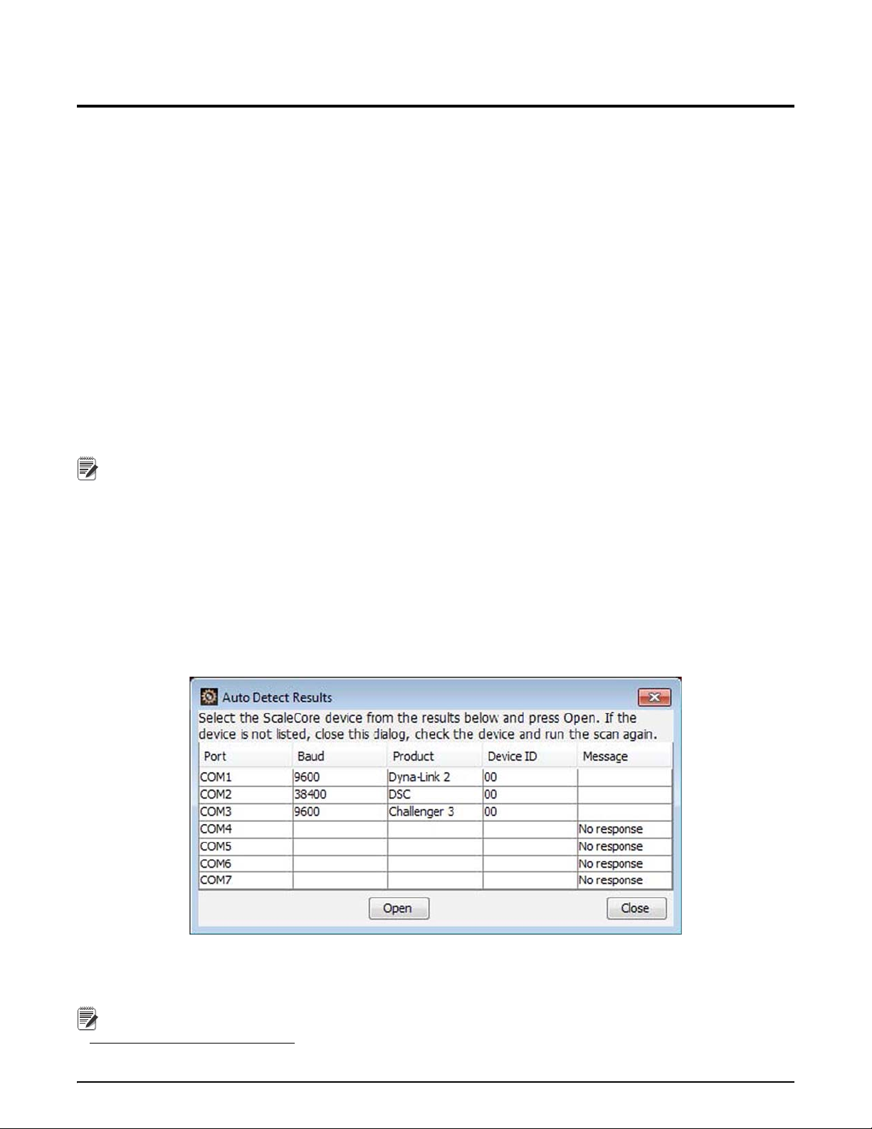
The ScaleCore device has an auto detect feature for serial interfaces.
1. Select
attached ScaleCore devices. When the scan is complete ScCMP will display the detected devices.
File, then Auto Detect Serial. The ScCMP will automatically scan all available serial ports for any
Figure 2-1. Auto Detect Serial Results Dialog
2. Select the device desired.
3. Press the
1. Microsoft, Encarta, MSN, and Windows are either registered trademarks or trademarks of Microsoft Corporation in the United States and/or other countries.
2 ScCMP Operator’s Manual
Open button to begin communicating with the device.
If your device is not found, close the dialog, check the device power and data connection to the computer, then
run the scan again.
Page 7
Manual Connection
The last used connection
parameters are
automatically entered.
Note
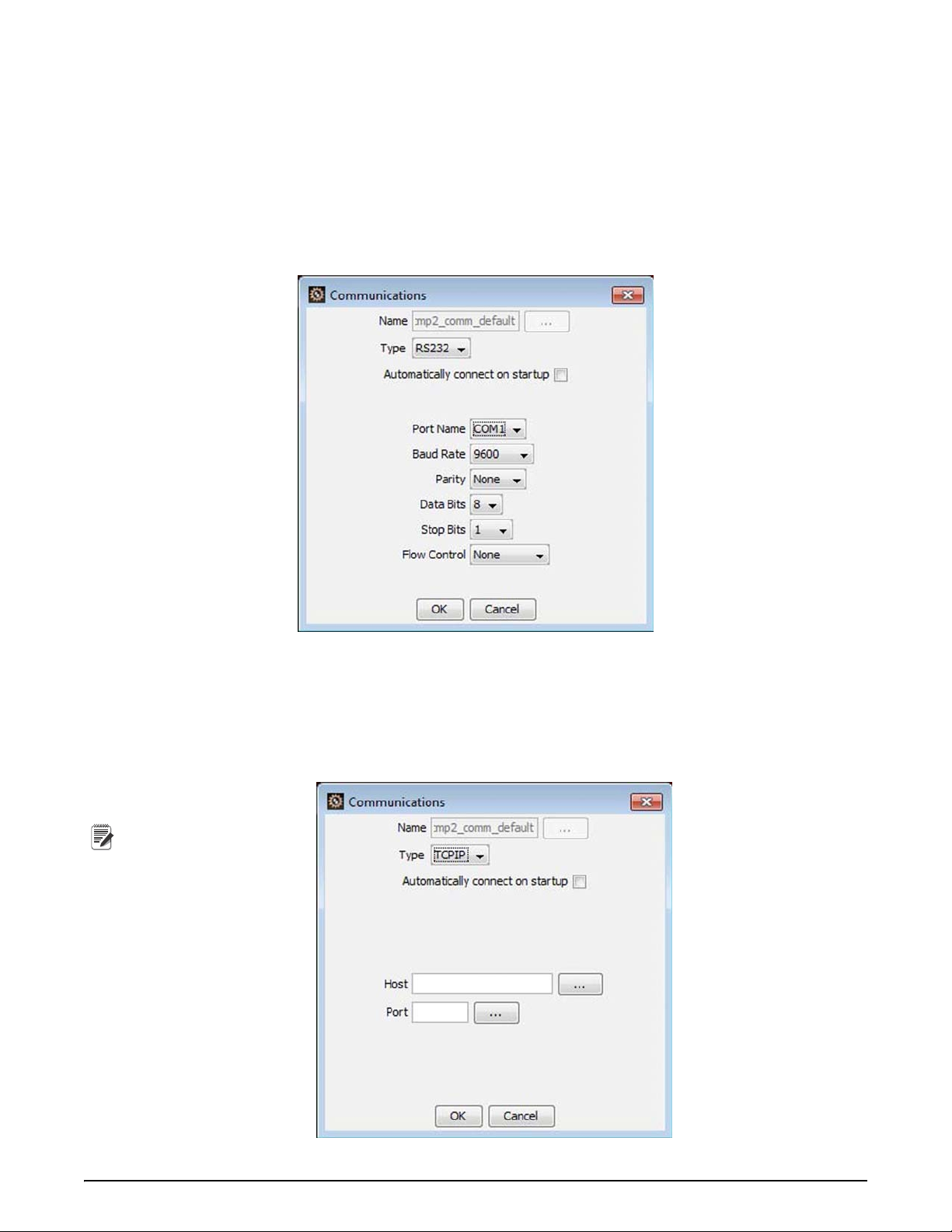
1. Select
File, then Open Communications. ScCMP will display the connection parameters dialog. This dialog
allows you to manually enter either Serial (RS-232) or IP host address and port for the device connection.
Typical serial connection parameters are:
- Baud Rate – 96
- Pari
ty – None
00 baud
- Data Bits – 8
op Bits – 1
- St
- Flow Contr
ol – None
Figure 2-2. Communications Dialog (RS-232)
2. Select the serial port name of the local computer port that the ScaleCore device is connected to.
3. Press
OK to open the connection.
Ethernet and WI-FI
Ethernet and Wi-Fi (802.11) communications require the IP addre
ss and port number of the ScaleCore device. The
address is specific to the device installation. The port is typically 2101.
Figure 2-3. Communications Dialog (TCP/IP)
Installation 3
Page 8

2.2.2 Connection State
When a connection is first opened, the ScCMP application is Searching state, searching the communications
interface for an attached ScaleCore device.
The application will continue to search the interface
connection is closed.
Figure 2-4. Searching Screen
When a device is found (a response is received), ScCMP will transition to the Discovery state. During which
ScCMP is reading the device configuration. This will typically take 2 to12 seconds depending on the
communications speed.
for a device indefinitely, or until the communication
Figure 2-5. Reading Device Screen
After the device configuration has been read, ScCMP will transition to the Normal state. The normal state allows
selection of one of the four device views, detailed in the next section.
Additional information on the connection stat
4 ScCMP Operator’s Manual
e can be found under the Event Monitor section (see Section 3.1.1).
Page 9
3.0 Views
The ScCMP application provides four main views when communicating with a ScaleCore device.
• Configuration View – All device configuration and setup controls are
• Data View – A complete view of all measured sensor data by the device.
• Single Meter – A virtual meter for a single load
• ABC Meter – A virtual meter for dual load systems that provide
monitor both load points, and a sum.
sensor system.
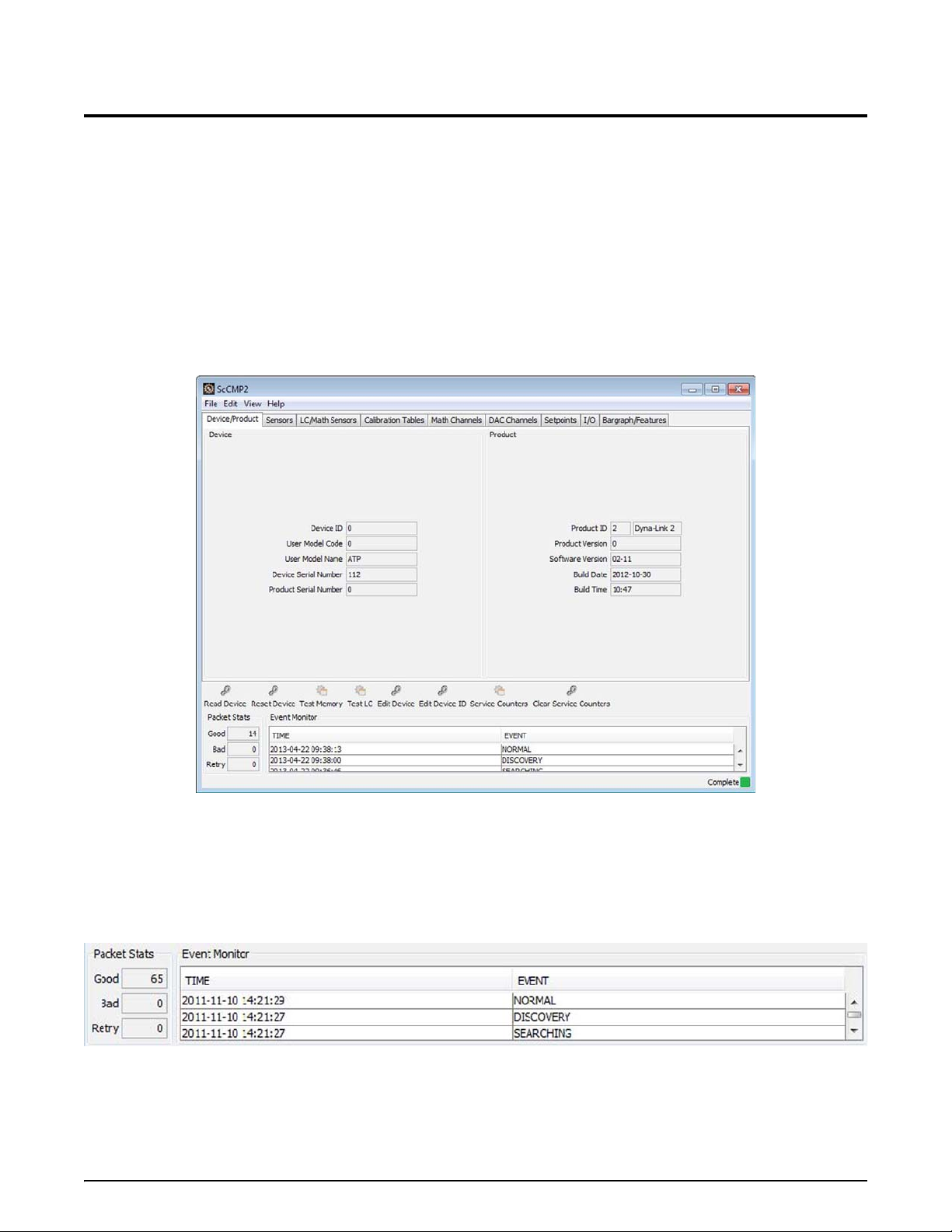
3.1 Configuration View
The configuration view of the active device provides a complete view of the ScaleCore device settings. This
interface is divided into tabbed panels that separate the different ScaleCore parameters into logical groups. Each
panel provides controls for entering configuration, viewing the current configuration settings and performing
related functions.
accessed from this view.
three simultaneous load sensor views to
Figure 3-1. Configuration View
Complete details on advanced device configuration can be found in Section 6.0.
3.1.1 Event Monitor
The event monitor is located at the bottom of the ScCMP configuration view. This provides a log of activities that
the ScCMP application is performing, plus statistics on the communications interface to monitor when
communication interruptions occur.
Figure 3-2. Event Monitor
Views 5
Page 10

Packet statistics displays the number of good, bad, and retry packets per second of an open
device connection. Communications with a ScaleCore device may be in one of five possible
states. The diagram shows the possible states and the flow between each.
Event Monitor States
DORMANT
Typically this state refers to a connection that is c
losed (no problem detected). If the
connection is open, this state indicates a fatal communications error. The connection should be
closed and device communications hardware confirmed before re-opening the connection.
SEARCHING
The searching state indicates the application is polling
the communications interface for a
ScaleCore device, that a device has not responded to polling yet. This is the expected default
state when a connection is first opened.
If the communication is unreliable, communication packets may be
lost and the application
may enter this state to confirm the device is still there. If this state persists, it likely indicates
the device is faulty, the communications configuration is incorrect or the connection is broken.
DISCOVERY
Every time a device is first 'discovered', the
application reads the entire device configuration to ensure the
application knows precisely the device it is talking to. This state indicates that process is happening. The device
configuration can be manually re-read, or may automatically be triggered after a large configuration change. This
state indicates good communications, but other user controls are blocked in this state. Typically to read an entire
device configuration will take 2 and 12 seconds depending on the communication connection.
NORMAL
The normal operating state indicates communications
are good and normal operations are working. Any enabled
user controls should not be blocked in this state.
CONFIGURING
The configuring state indicates the device configuration is being change
d in response to user input. When a device
is in the configuration state, it should be left powered on to complete all memory write operations required. This
state indicates good communications, however other user functions may be blocked while the configuration is
being written. Additionally , depending on the configuration ch ange, some or all of the device configuration may be
re-read. Therefore, after the configuring state, communications may switch to the discovery state. This is normal.
6 ScCMP Operator’s Manual
Page 11
3.2 Data Views
Note
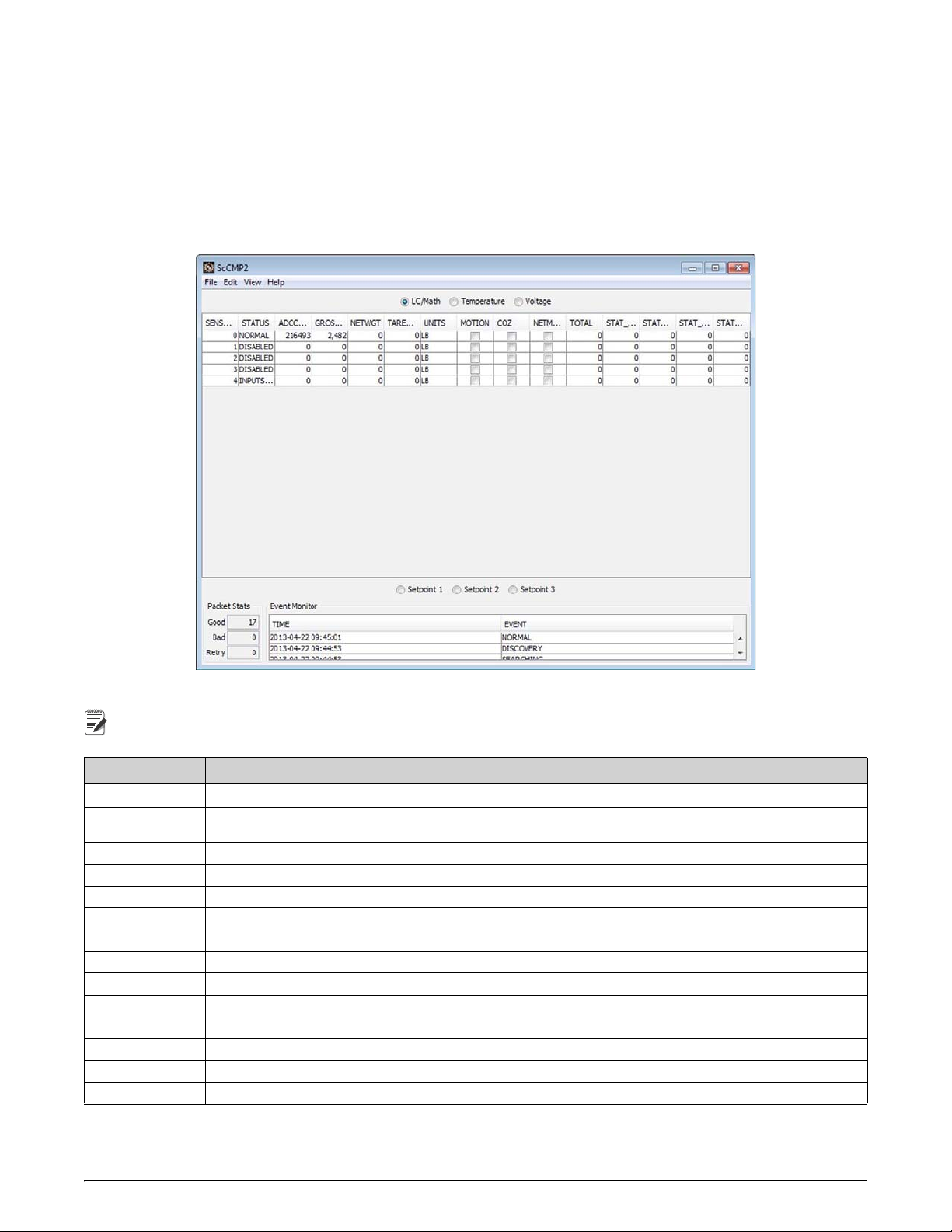
The data views provide a read-only display of all sensor data. Sensors include weight, math, temperature and
voltage.
At the bottom of this display are setpoint indicators for
3.2.1 LC/Math Sensor Data
The LC/Math Sensor data view shows weight including ADC count, calibrated weight value with indicators
(motion, CoZ) and total/statistics data.
three setpoints.
Figure 3-3. Data View – LC/Math
ADC, total and statistics may not be updated if the monitor is not enabled from the Edit menu.
Parameter Description
Sensor ID Sensor index. Typical range 0 to 4 for
Status
ADC Count The ADC (Analog to Digital Converter) coun
Gross Weight The calibrated gross weight value.
Net Weight The calibrated net weight value.
Tare Weight The current tare weight value.
Units The current unit of measure.
Motion Indicates motion on the sensor input.
CoZ Center of Zero indication for the sensor Ne
To ta l The total accumulator value.
Stat. SumSqr Calculated statistics value based on the total feature.
Stat. Num Ttl Number of totals registered in the total accumulator.
Stat. Min Ttl The minimum total value recor
Stat. Max Ttl The maximum total value recorded in the accumulator.
Current status of the sensor. This will indicate under load, overload,
other sensor status messages.
load and math sensors.
t as read from the sensor input.
t Mode Indicates if the scale is currently in net or gross mode.
ded in the accumulator.
Table 3-1. LC/Math Sensor Data Parameters
under range, over range, disabled, and
Views 7
Page 12
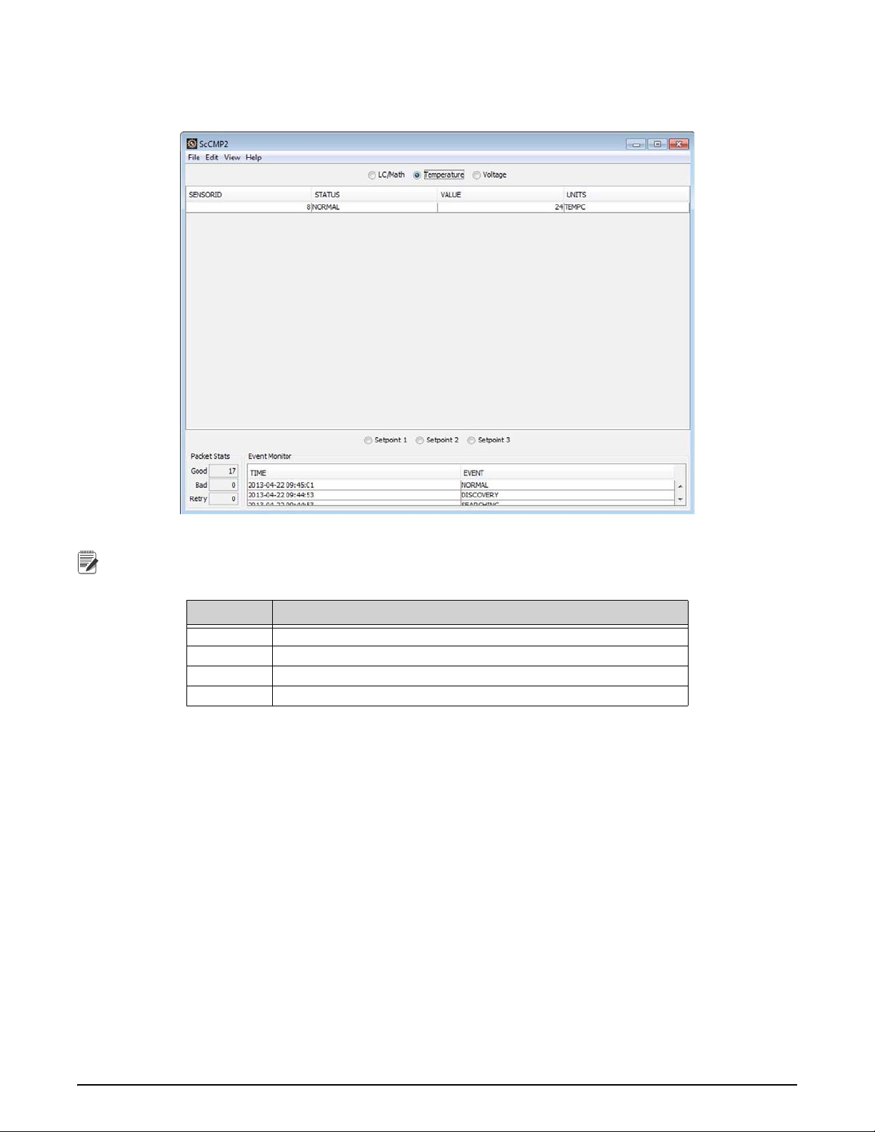
3.2.2 Temperature
Note
A ScaleCore device will typically have a temperature sensor. The measured temperature is displayed on this
interface.
Figure 3-4. Data View – Temperature
The temperature data will not be updated if the monitor is not enabled from the Edit menu.
Parameter Description
Sensor ID Typically 8 for temperature sensors.
Status Current status of the sensor.
Value The measured temperature value.
Units The current units of measure for temperature.
Table 3-2. Temperature Parameters
8 ScCMP Operator’s Manual
Page 13
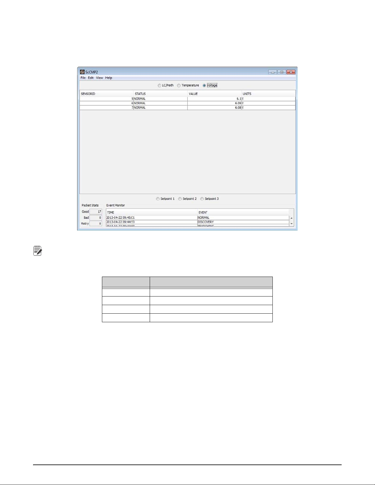
3.2.3 Voltage
Note
A ScaleCore device may have voltage sensors. Typically these are used for monitoring power (battery) levels. The
meaning of each voltage sensor is dependent on the device.
Please refer to the specific device User Guide for more details.
Figure 3-5. Data View - Voltage
The voltage data will not be updated if the monitor is not enabled from the Edit menu.
Parameter Description
Sensor ID Typical range 5-7 for voltage sensors.
Status Current status of the sensor.
Value The measured voltage value.
Units The current units of measure (Volt).
Table 3-3. Voltage Pa rameters
Views 9
Page 14
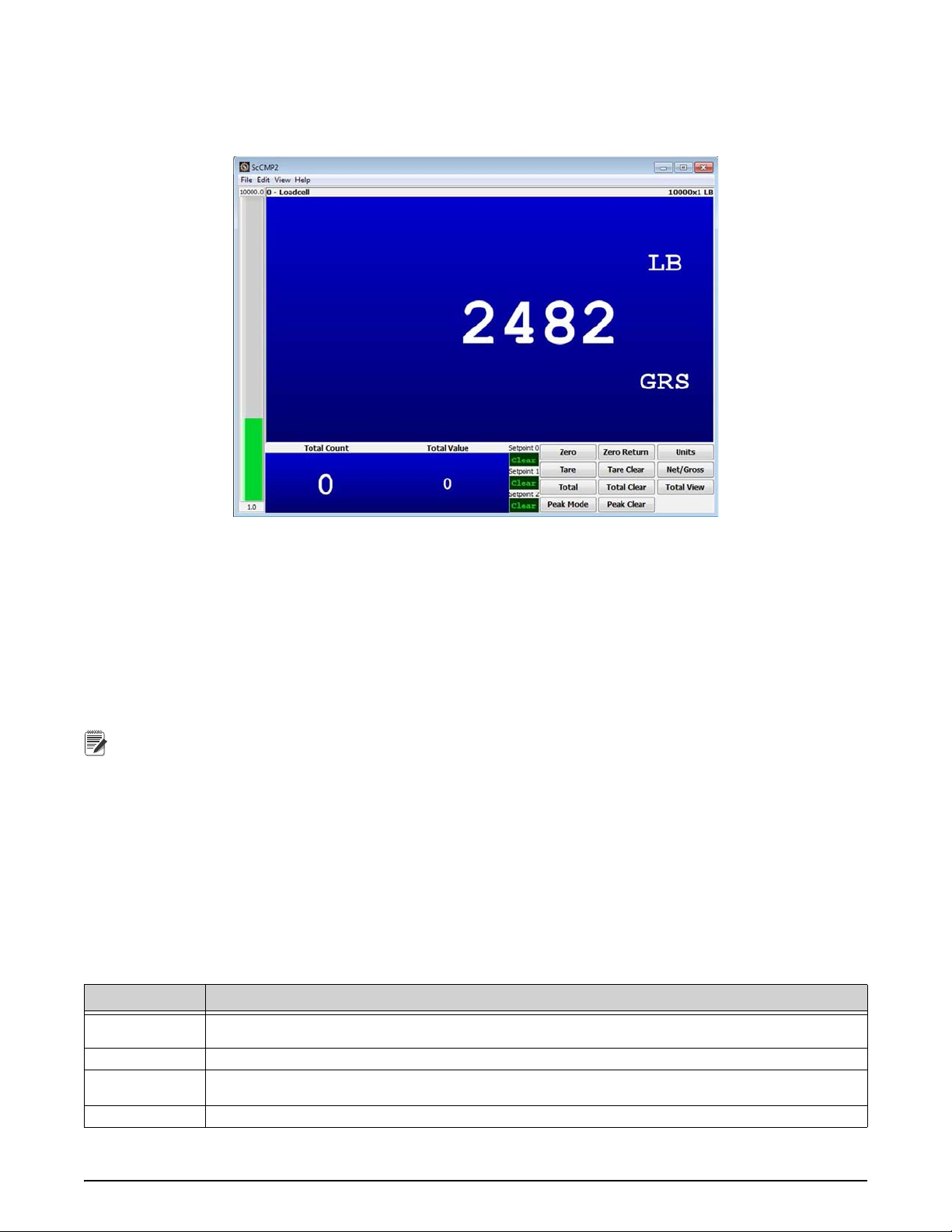
3.3 Single Meter View
Note
The single meter view provides a virtual meter interface that is intended for single-load-point weighing
applications. Following is an example single meter view in ScCMP.
Figure 3-6. Single Meter View
The main weight display shows the current load on the system, the units of measure, the weight mode, plus
provides motion indication and center-of-zero (CoZ) indication. The currently selected sensor and the capacity of
the sensor are displayed at the top. The display defaults to the first load sensor in the ScaleCore device. To view
another sensor, click anywhere on the main weight indicator and a dialog box will appear to enter another sensor
number. If there are any errors with the currently selected sensor, a large error message will be displayed on the
screen indicating what the fault is.
total and total count information is displayed at the bottom left of the single meter view. This is the total
The
information for the currently selected sensor. The total function supports several modes of manual and auto total.
Details of the total configuration can be viewed in Section 6.0 on page 19.
Total and statistics may not be updated if the monitor is not enabled from the Edit menu.
Three setpoint indicators showing the Set/Clear state of each setpoint. These setpoints may not be related to the
currently displayed sensor. Setpoint configuration can be viewed in Section 6.0 on page 19.
The bargraph ind
icator on the left of the display follows the bargraph function in the ScaleCore device. The first
and last segment values are displayed at the bottom and top of the bargraph respectively. Bargraph configuration
can be viewed in Section 6.0 on page 19.
The scale
function controls on the lower right allow the ScaleCore device to be controlled from the computer.
Details of the scale functions are found in Table 3-4.
3.3.1 Scale Functions
Following are the scale functions supported by ScCMP from the Single Meter and ABC Meter views.
Function Description
Zero
Zero Return Return to the last zero value. Similar to an 'undo' zero button.
Ta re
Tare Clear Remove any tare weight and switch to
10 ScCMP Operator’s Manual
Zero the weight on the scale. The zero range may be limi
details see Section 6.0 on page 19.
Remove the weight on the scale and switch to Net weigh mode. Additional details of the Tare function are in
Section 6.0 on page 19.
Gross weigh mode.
Table 3-4. Scale Functions
ted depending on the scale mode. For complete
Page 15

Function Description
Note
Net/Gross
Units Change the units of measure for the current sensor.
To ta l
Clear Total Clear all accumulated weight from the total r
View Total
Peak Mode
Peak Clear Clear the current peak value and track a new peak value.
Toggle the display between net and gross mode without clearing the current tare weight from the device (if
there is a tare weight).
Manual total button
configuration. Additional details are in Section 6.0 on page 19.
A control that will force a single read of the current sensor total data. This can be used when the total and
statistics monitor is disabled in the Edit menu.
Toggles the device in and out of peak mode. The
products. Refer to your specific device manual for more details.
for accumulating weight on the sensor. This function relies on the total function
egister in the current sensor.
peak function may not be supported by all ScaleCore
Table 3-4. Scale Functions
3.4 ABC Meter View
The ABC meter view provides a virtual meter interface that is intended for dual-load-point weighing applications
that also monitors the sum of both loads (commonly referred to as A+B=C or simply ABC). Following is an
example ABC meter view in ScCMP.
Figure 3-7. ABC Meter View
The main weight display shows three virtual indicators (similar to the single meter view) with the current load on
the system, the units of measure, the weight mode, plus provides motion indication and center-of-zero (CoZ)
indication. The bottom left is A, the bottom right is B, and the top center is C. The radio buttons above the scale
function controls select which display is currently active for control. The currently active indicator will be
highlighted blue, the others will be a darker blue. Each of the three virtual indicators can be selected to show any
sensor. The default is to show the first weight sensors in A and B, then show the first math channel in C. Click on
the virtual indicator and a dialog will prompt for the sensor you wish to display in that indicator.
The total and statistics view is a complete table of all weight and math sensors. T
he total function supports several
modes of manual and auto total. Details of the total configuration can be viewed in Section 6.0 on page 19.
Total and statistics may not be updated if the monitor is not enabled from the Edit menu.
Three setpoint indicators show the Set/Clear state of each setpoint. These setpoints may not be related to the
currently displayed sensors. Setpoint configuration can be viewed in Section 6.0 on page 19.
The scale
function controls on the lower right allow the ScaleCore device to be controlled from the computer.
Details of the scale functions are found in Table 3-4.
Views 11
Page 16

4.0 Calibration Tools
ScCMP provides some core tools for configuring and setting up a ScaleCore product. These tools include Sensor
Calibration, DAC Calibration and Manual DAC control for testing.
4.1 Sensor Calibration
ScCMP provides a nice visual interface for performing the available types of sensor (Load Cell) calibration to
ensure the ScaleCore product is accurate. The available methods of calibration are:
• Initial Calibration – Enter scale
reference calibration points.
• Re-Calibration – Using c
reference calibration points.
• Cal-N
The ScCMP sensor (load cell) calibration interface
Status interface. This shows the currently selected load cell sensor. The current ADC (Analog to Digital converter
count) and calibrated weight value. The calibration status, and any calibration error code received from the
ScaleCore device. Plus controls to read the current Cal-Number value of a calibrated load cell sensor.
The right pane provides the calibration controls interface. At the top of th
each calibration step requires.
umber – Enter a reference calibration number without the requirement of test weights.
capacity, resolution, and unit of measure in addition to setting zero and span
urrent scale capacity, resolution, and unit of measure to enter new zero and span
is divided into two sections. The left provides the Calibration
is will be some brief instructions for what
Figure 4-1. SCCMP Sensor Calibration Dialog
The following sections discuss each calibration type and the steps involved.
12 ScCMP Operator’s Manual
Page 17

4.1.1 Initial Calibration
Note
Note
Note
Note
Note
To perform an initial calibration:
1. Select the sensor (load cell) to calibrate from the
2. Select
3. Press the
Initial Calibration from the drop down box in the controls interface
Next button.
Capacity and Unit of Measure
4. Enter the full scale capacity of the selected sensor (load cell) and the unit
dialog.
5. Press
Next to continue.
Resolution
Enter the scale resolution or countby value.
6. Based on the entered calibration capacity, Sc
desired countby value.
7. Press
Next to continue.
Zero Reference Point
8. Unload the scale (with the exception of any lift rigging req
(unloaded) reference point.
9. Once the scale is unloaded and stable, press
The ADC Count displayed on the left status panel can be used as a reference to indicate the current load and
stability. This value will never be perfectly stable, in ideal situati
Span Reference Point
10. Load the scale with a known test weight, plus the same lift rigging
11. Enter the test weight value into the calibration dialog.
12. Once the scale is loaded and stable, press
As above, the ADC Count display can be used as a reference to indicate the current load and stability. This value
should be different from the zero reference ADC Count value. If no
selected for calibration.
The Cal Points tab provides a look at the current cali
points will be equal at this point.
Additional Span Reference Point(s)
left status panel.
CMP will read the available values for countby. Select the
uired during calibration) to establish the zero
Next to continue.
ons expect the value to jump 50 counts or more.
used when establishing the zero reference.
Next to continue.
t, ensure you have the correct sensor
bration table. Since there is only one point entered, all
of measure in the calibration control
If no additional span reference points are required, skip to step 16.
13. To establish additional span points, load the scale with the next test value.
14. Enter the test value into the calibration
15. Press the
Next button.
control dialog.
Save/Complete Calibration
16. To save and complete this cali
17. Wait for ScCMP
The Cal Points tab provides a look at the current calibration table. From this table you can see the ADC Count
and the calibration value that was captured for each reference point.
to complete calibration (confirm by checking the Status value on the left).
bration, press the Save/Complete button.
Calibration Tools 13
Page 18

4.1.2 Re-Calibration
Note
Note
Note
Note
Note
Note
Note
To perform a Re-Calibration:
1. Select the sensor (load cell) to calibrate from the
2. Select
3. Press the
Re-Calibration from the drop down box in the controls interface.
Next button.
Zero Reference Point
4. Unload the scale (with the exception of any lift rigging req
(unloaded) reference point.
5. Once the scale is unloaded and stable, press
The ADC Count displayed on the left status panel can be used as a reference to indicate the current load and
stability. This value will never be perfectly stable, in ideal situati
Span Reference Point
6. Load the scale with a known test weight, plus the same lift rigging
7. Enter the test weight value
into the calibration dialog.
8. Once the scale is loaded and stable, press
As above, the ADC Count display can be used as a reference to indicate the current load and stability. This value
should be different from the zero reference ADC Count value. If no
selected for calibration.
The Cal Points tab provides a look at the current cali
points will be equal at this point.
Additional Span Reference Point(s)
left status panel.
Next to continue.
Next to continue.
bration table. Since there is only one point entered, all
uired during calibration) to establish the zero
ons expect the value to jump 50 counts or more.
used when establishing the zero reference.
t, ensure you have the correct sensor
If no additional span reference points are required, skip to step 12.
9. To establish additional span points, load the scale with the next test value.
10. Enter the test value into the calibration
11. Press the
Next button.
control dialog.
Save/Complete Calibration
12. To save and complete this cali
13. Wait for ScCMP
The Cal Points tab provides a look at the current calibration table. From this table you can see the ADC Count
and the calibration value that was captured for each reference point.
to complete calibration (confirm by checking the Status value on the left).
bration, press the Save/Complete button.
4.1.3 Cal-Number
To perform a Cal-Number:
1. Select the sensor (load cell) to calibrate from the
2. Select
3. Press the
Cal-Number from the drop down box in the controls interface
Next button.
Zero Reference Point
4. Unload the scale to establish the zero (unloaded) reference
5. Once the scale is unloaded and stable, press
The ADC Count displayed on the left status panel can be used as a reference to indicate the current load and
stability. This value will never be perfectly stable, in ideal situati
left status panel.
point.
Next to continue.
ons expect the value to jump 50 counts or more.
Enter Cal-Number Value
6. Enter the Cal-Number value in t
7. Press
14 ScCMP Operator’s Manual
Next to complete the Cal-Number calibration.
The Cal-Number value may be found stamped on the load cell or recorded in previous calibration records.
he calibration control dialog.
Page 19

4.2 DAC Controls
Note
Note
Note
Note
ScCMP provides controls for DAC (Digital to Analog) output functions in a ScaleCore product. Controls include
calibration and manual control.
DAC outputs may not be available in all ScaleCore family products.
4.2.1 Calibrate DAC
ScCMP provides an interface for performing calibration of the available Digital to Analog Converter (DAC)
outputs. The DAC calibration interface is divided into two sections.
• The left provides the DAC Status interface. This show
- Current calibration values – Offset, Gain, Minimum and Maximum Span.
- DAC status – Calibrated, Enabled, In Cal, and Manual Mode.
- DAC configuration relative to input sensor – Sensor ID, Units, Value Type, Minimum and Maximum
Va
lue.
• The right pane provides the calibration controls
- At the top of this will be some brief instructions for what
Please reference your specific hardware user guide for details on connecting to and measuring the DAC output.
To perform a DAC calibration:
1. Select the DAC output to calibrate from the left status panel.
2. Press the
Next button.
Offset
The DAC voltage output will go to a mid-range value. T
3. It should be approximately equal to
the mid-range of the desired DAC output. If needed, adjust the output
value up or down with the calibration controls.
4. Press the
Next button to continue.
s the currently selected DAC output.
interface.
each calibration step requires.
o adjust the offset:
Typically this value is left at default (0).
Gain
The DAC voltage output will go to a full scale
5. If needed, adjust the output value up or down with the calibrati
6. Press the
Next button to continue.
Typically this value is left at default (0).
value. Adjust the gain:
on controls.
Minimum Span
The DAC voltage output will go to the absolute minimum va
7. This value coincides with the minimum va
lue assigned to the sensor configuration. If needed, adjust the
lue. Adjust the minimum span:
output value up or down with the calibration controls.
8. Press the
Next button to continue.
Maximum Span
The DAC voltage output will go to a full scale value. A
djust the maximum span:
9. This value coincides with the maximum value assigned to the sensor configuration. If ne
output value up or down with the calibration controls.
10. Press the
Next button to complete the calibration.
eded, adjust the
Calibration Tools 15
Page 20

4.2.2 Manual DAC
Note
Note
ScCMP provides an interface for manually controlling the available DAC (Digital to Analog Converter) outputs.
This is a useful tool when installing or interfacing the DAC outputs to other equipment without having to apply real
load to the lift equipment.
DAC outputs may not be available in all products.
The ScCMP manual DAC control interface is divided into two sections.
• The left provides the DAC Status interface. This show
- Current calibration values – Offset, Gain, Minimum and Maximum Span.
- DAC status – Calibrated, Enabled, In Cal, and Manual Mode.
- DAC configuration relative to input sensor – Sensor ID, Units, Value Type, Minimum and Maximum
Va
lue.
• The right pane provides the calibration controls
- At the top of this will be some brief instructions for what
Please reference your specific hardware user guide for details on connecting to and measuring the DAC output.
To enable the manual DAC output:
1. Select the desired DAC output
2. Press the
Enable toggle button (observe the Manual Mode indicator on the left status panel indicate true).
3. The slider control allows adjusting th
from the left status panel.
e DAC value over the full range (0-4095). Adjust the slider bar to the
desired value.
4. Press the
5. When finished, press the
Update button to apply the value to the DAC output.
Enable toggle button to go back to normal DAC mode (observe the Manual Mode
indicator on the left status panel indicate false).
s the currently selected DAC output.
interface.
each calibration step requires.
16 ScCMP Operator’s Manual
Page 21

5.0 Print Setup
Note
ScCMP Provides an interface to configure the printing capabilities of a ScaleCore family product. There are two
aspects of configuring printing in ScaleCore family products. First is what information is to be printed, then how
the information will be printed.
Printing capability may not be available in all ScaleCore family products.
5.1 Print Information
The printed information is defined by the Print Formatters and the Print Composite. The Print Formatter defines
group of information that is printed. A Print Composite combines a list of Print Formatters to make more advanced
print configurations.
5.1.1 Print Formatters
Devices that support printing come with default standard print formatters that can be loaded from the dialog box in
Figure 5-1.
Figure 5-1. Print Formatter Dialog (Pre-Configured)
Print Setup 17
Page 22

Custom print formatters can be generated with the help of the custom interface within the Print Formatter Dialog,
shown in Figure 5-2.
Figure 5-2. Print Formatter Dialog (Custom)
The bottom of the Print Formatter Dialog shows the print formatter index that is being edited and the current edit
value in the text box. The value can be typed in, loaded from a pre-configured value or built from the custom
interface.
5.1.2 Print Composite
The print composite lists which of the Print Formatters will be printed and the sequence. The default print
composite '12345' will print all five of the Print Formatter configuration strings in sequence.
Figure 5-3. Print Mode/Composite Dialog
5.2 Print Mode
The Print Mode defines how/when the device will print the configured information. Following are the typically
supported print modes.
• Disabled – Device will not print.
• On Command – A button must be pressed, or command sent for the
• Stable Load – When a load is picked up and stabil
• Continuous – The device will continuously print with
18 ScCMP Operator’s Manual
ized (no motion) the device will print.
the interval defined by the Print Mode.
device to print.
Page 23

6.0 Advanced Configuration
Note
The advanced view provides complete list of all features and parameters within a ScaleCore device.
Before making changes to a ScaleCore device, it is advised that you capture the current device configuration to
the ScCMP database or a separate file. This way if any configurat
fully understood, the original device configuration can always be reloaded and restored. For details of how to do
this, see Section 7.0 on page 32.
6.1 Device/Product
The device and product information provides system identification and configuration details.
ions are applied that are not wanted or not
Figure 6-1. Configuration View - Device/Product
6.1.1 Parameters
Parameter Description
Device
Device ID
User Model Code A user defined model code. Typically used to
User Model Name
Device Serial Number Unique, embedded serial number of the Sca
Product Serial Number Serial number of the ScaleCore product.
Product ID Product index range 0 to 255, followed by the identified product name.
Product Version Product version ID range from 0 to 255. Identifies sub c
Software Version Software version name identification string.
Build Date Software built date.
Build Time Software built time.
Device communications ID number for networking. Typically a value of 0 for scales and a value other
than 0 for indicators.
index custom systems.
A user defined model name. Value may appear on scale display dur
is 6 excluded null char.
leCore processor board. Not editable.
Product
lassifications of a ScaleCore product.
Table 6-1. Device/Product Parameters
ing test sequence. Name length
Advanced Configuration 19
Page 24

6.1.2 Controls
Important
Important
Read Device – switch to discovery mode and re-read (refresh) the entire device configuration.
Reset Device – instruc
Configuration and calibration in the ScaleCore device will be lost.
ts the ScaleCore device to perform an internal software reset.
Test Memory – performs a check of the ScaleCore device memory.
Test LC
– the load cell bridge test is a troubleshooting tool that tests the connections to a load cell and attempts to
indicate which physical wire is open or shorted for a load cell connection.
Edit Device – allows editing
Edit Device ID – a
llows editing of the ScaleCore communications Device ID. It is not recommended to change
of the User mode Code and name.
this value.
6.1.3 Service Counters
Read the service counters from the ScaleCore device. These service counters are used as a load cell fatigue
monitor.
Lift count
details on configuring this threshold value, reference Edit Lift Counter section.
Overload count – indicates
Clear Service Counters
Reset all service counters back to zero.
– indicates the number of times a sensor (load cell) has exceeded a configurable load threshold. For
the number of times a sensor (load cell) has exceeded the calibration capacity value.
If the overload service counter is other than zero, it may indicate misuse of the load sensing device. It is
strongly recommended that all load beari
ng equipment be inspected if it is regularly misused.
20 ScCMP Operator’s Manual
Page 25

6.2 Sensors
The advanced sensor view provides a list of all sensor types and their associated configuration.
Figure 6-2. Configuration View - Sensors
6.2.1 Parameters
Parameter Description
ID Sensor ID index for every type of sensor. Typical range 0 to 16.
Enabled Enable or Disable the sensor.
Ty pe Sensor type, dependent on the hardware configuration.
Name Name of this sensor. Maximum number of characters is 20.
CnvSpeed
ACExc AC Excitation feature enabl
TempComp Temperature Compensation feature enabled. This feature i
Vref Voltage Reference enable. This featur
SWFilter The software filter level for the sensor. Typical range
Motion Enabled Enable or Disable motion detection.
AZM Enabled Enable or Disable AZM (Auto Zer
Zero at Power Up Enable or Disable automatic zero of load at power up.
Standard Mode Set the weighing mode (Industry, NTEP, OIML, 1-Unit).
Sensor conversion speed range 1 to 15.
hardware dependent.
ed. This feature is not yet supported in many ScaleCore products.
o Maintenance) algorithm.
Table 6-2. Sensor Parameters
Smaller value faster the speed and more noise. This value is
s not yet supported in many ScaleCore products.
e is hardware dependent.
0-3 where the lower number is less filtering.
6.2.2 Controls
Edit Sensor – This control allows editing the sensor configuration parameters.
Edit Standard Mode – This control allows editing of
Zero at power up.
the standard mode, including motion detection, AZM and
Advanced Configuration 21
Page 26
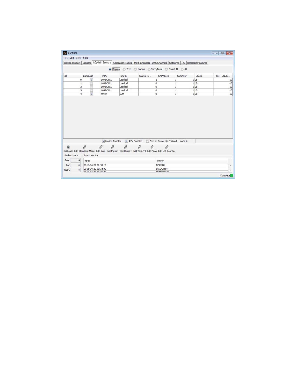
6.3 LC/Math Sensors
The advanced LC/Math Sensor view provides a list of all Load cell and Math sensors and their associated
configuration. Similar to the Sensor view, but specific for these two types of sensors. This is where most of the
Scale parameters are set.
Figure 6-3. Configuration View - LC/Math Sensors
22 ScCMP Operator’s Manual
Page 27

6.3.1 Parameters
Parameter Description
ID Sensor index. Typical range 0 to 4 for load and math sensors.
Enabled
Ty pe Sensor type (Loadcell or Math).
Name Name of this sensor. Maximum number of characters is 20.
SWFilter The software filter level for the sensor. Typical range 0-3 where the lower number is less filtering.
Capacity The display capacity (less than or equal to the calibration capacity).
Countby The display countby (greater than or equal to the calibration countby).
Units The display unit of measure.
Percent Underload The percentage of under load readings before giving an under load error.
Zero Band Hi Zero high band in terms of percentage of capacity, range 1 to 100.
Zero Band Lo Zero low band in terms of percentage of capacity, range 1 to 20.
AZM Range AZM range in d.
AZM Period AZM period in ticks (each tick is 50 milliseconds).
Power Up Zero Hi Power up Zero high band in term of percentage of capacity, range 1 to 25.
Power Up Zero Lo Power up Zero low band in term of percentage of capacity, range 1 to 20.
Motion Period Motion window period in ticks (each tick is 50 milliseconds).
Motion Band Motion detection band in d of a load cell, range 0 to 255, 0==1/2 d, 1==1d and so on.
Motion Pending Time
LC Mode Net/Gross
Tare Auto Clear Sets the Tare Auto Clear function to Disabled, Enabled, or On Total.
To t a l M o d e
Drop Threshold Threshold in percentage of capacity to drop below before totaling be allowed.
Rise Threshold Threshold in percentage of capacity to rise above before totaling be allowed.
Minimum Stable Time Minimum stable time before it can be total.
Total On Accept Upper Upper bound weight of on accept total mode.
Total On Accept Lower Lower bound weight of on accept total mode.
Capacity Conversion
Lift Threshold
Drop Threshold
Sample Speed Sensor sampling speed for all sensor in peak hold mode.
Enable or Disable the sensor. Disabling an unused sensor will improve performance of other enabled
sensors.
Display
Zero
Motion
Motion pending time in ticks (each tick is 50 milliseconds). The time required to wait for a stable load
before zero, tare or total actions can be performed.
Tare /Tota l
Load cell total mode.
• Disabled
•Auto Load
•Auto Norm
•Auto Peak
• Load Drop
•On Accept
• On Command (manual)
Selects between true and half capacity conversion. Example: 1000 lb scale true conversion is 454 kg
where half conversion is 500 kg.
Peak/Lift
Configurable upper threshold for the lift counter. Lift threshold as percentage of capacity. 0==0.5%, 1 to
100 means 1 to 100%. Above this threshold is a lift event.
Configurable lower threshold for the lift counter. Drop threshold as percentage of capacity. 0==0.5%, 1
to 100 means 1 to 100%. Below this threshold is a drop event.
Table 6-3. Load Cell and Math Sensor Parameters
Advanced Configuration 23
Page 28

Parameter Description
Standard Mode
Motion Enabled Enable or Disable motion detection
AZM Enabled Enable or Disable AZM (Auto Zero Maintenance)
Zero at Power Up Enable
Standard Mode
Set the weighing mode (Industry, NTEP, OIML, 1-Unit).
Table 6-3. Load Cell and Math Sensor Parameters
6.3.2 Controls
Calibrate – Sensor calibration interface. Details provided in the Section 4.1 on page 12.
Edit Standard Mode
Zero at power up.
Edit Zero Configuration –
parameters and power up at zero range. These values are stored separately for each of the standard modes (i.e.
Industry, NTEP, OIML).
Edit Motion Configuration – Edit the sensor
and pending time.
Edit Display Configuration –
units, and percent under load range. Note that the capacity and count by can be adjusted without having to
recalibrate a sensor. The capacity can be adjusted less than the calibration capacity. The countby can be adjusted
greater than the calibration countby.
Edit Tare/Total Configuration
mode, total thresholds, total stable time, and total on accept thresholds.
Edit Peak Configuration
Edit Lift Counter – Edit the sensor
– This control allows editing of the standard mode, including motion detection, AZM and
Edit the sensor Zero parameters. This includes adjusting the zero range, AZM
motion detection parameters. This includes the motion period, band,
Edit the sensor display parameters. This includes adjusting the capacity, countby,
– Edit the sensor Tare and Total parameters. This includes Tare Auto Clear, Total
– Edit the sample speed used when recording peak lift values.
lift counter thresholds. These parameters relate to the service counters.
6.4 Calibration Tables
The advanced Calibration Tables view provides a list of all sensor calibration tables and their associated
configuration.
24 ScCMP Operator’s Manual
Figure 6-4. Configuration View - Calibration Tables
Page 29

6.4.1 Parameters
Important
Parameter Description
Table cal points
Cal Table Calibration Table Number.
Sensor ID Sensor ID associated with this cal table.
Status Status of this cal table.
Capacity Capacity of a sensor.
Count by Countby of a sensor.
Units Sensor value unit.
Te m p Z o n e
Cal Point Cal point index.
ADC Count ADC count.
Val ue Value of sensor. Weight for load cell.
Temperature zone for this calibration table (temperature compensated calibration not available in all
systems).
Table cal points
Table 6-4. Calibration Table Parameters
6.4.2 Controls
Edit Calibration Point – allows manually editing a single calibration point within a calibration table without
performing a calibration.
Adjusting calibration table points will affect the current sensor calibration.
Edit Cal Table – allows editing of the ADC count and Values in a table by typing into a spreadsheet style interface.
Following diagram shows the Calibration Table Editor.
Figure 6-5. Calibration Table Editor
Additionally, a convenience function is provided to Zero the calibration table. This function accepts numeric input
as a value to be added to every ADC count in the editor.
This function is helpful when transferring
calibration from one set of electronics to another and correcting for zero
offsets.
Advanced Configuration 25
Page 30
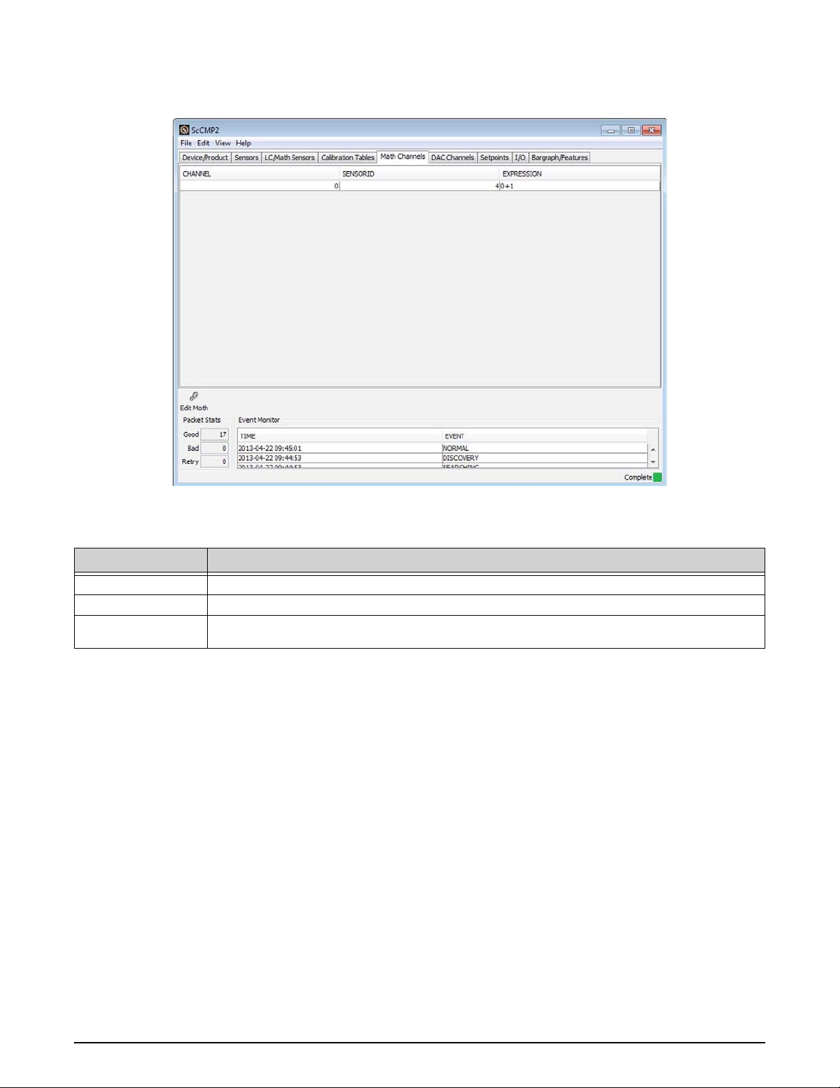
6.5 Math Channels
The advanced Math Channels view provides a list of all math channels and their associated configuration.
Figure 6-6. Configuration View - Math Channels
6.5.1 Parameters
Parameter Description
Channel The math channel index.
Sensor ID The sensor number that is assigned to this math channel
Expression
Math expression. 0+1+2 means value of sensor0 + sensor1 + sensor2. Now it only supports '+' only
and input
sensor must be a real physical load cell.
Table 6-5. Math Channel Parameters
. Hard coded number 4 for all ScaleCore.
6.5.2 Controls
Edit Math Channel – allows complete configuration of the math channel parameters.
26 ScCMP Operator’s Manual
Page 31

6.6 DAC Channels
Note
The advanced DAC Channels view provides a list of all DAC channels and their associated configuration.
DAC outputs are not available on all products.
Figure 6-7. Configuration View - DAC Channels
6.6.1 Parameters
Parameter Description
Channel DAC channel range 0 to 1.
Calibrated Indicates the DAC channel is calibrated.
Enabled Indicates the DAC channel is enabled.
In Cal Indicates the DAC channel is in calibration.
Manual Mode Indicates the DAC channel is in manual mode.
Sensor ID Source Sensor ID. Range 0 to 16.
Units Source Sensor value unit.
Val ue Type Source Sensor value type.
Value Minimum Source sensor value for min span point of DAC output.
Value Maximum Source sensor value for max span poin
t of DAC output.
Table 6-6. DAC Channel Parameters
6.6.2 Controls
Calibrate DAC – Provides an interface to calibrate the DAC outputs. See Section 4.2.1 on page 15.
Manual DAC Tool – Provides a manual control of DAC outputs for diagnostic and testing. See Section 4.2.2 on
page 16.
Edit DAC Configuration – The edit DAC configuration dialog allows complete configuration of the DAC
parameters. This configuration associates the DAC with an input sensor and scales the DAC output from the sensor
input as desired.
Advanced Configuration 27
Page 32

6.7 Setpoints
The advanced view allows editing of ScaleCore setpoints feature. Setpoints provide a trip point for load values.
Figure 6-8. Configuration View - Setpoints
6.7.1 Parameters
Parameter Description
Number Setpoint number range 0 to 2.
Sensor Sensor ID. Range 0 to 16.
Enabled Enable or Disable the setpoint.
Cmp Logic Comparison logic and its value mode flags.
Val ue Mode 0 == net_gross, 1== gross, 2==total.
Hysteresis Setpoint hysteresis in countby.
Val ue Comparison value. Its unit is assumed to be same as unit of viewing countby.
Table 6-7. Setpoint Parameters
2=='<', 1=='>'
6.7.2 Controls
Edit Setpoint – The edit setpoint dialog allows complete configuration of the setpoint parameters.
28 ScCMP Operator’s Manual
Page 33

6.8 I/O
The advanced view allows editing of ScaleCore listeners feature. This controls the machine to machine
communications interfaces.
Figure 6-9. Configuration View - I/O
6.8.1 Parameters
Parameter Description
Listeners
Number Stream listener number or ID. It range from 0 to 2.
Destination ID
Stream Type Stream type of this stream listener.
Sensor ID Sensor ID. Range 0 to 16. The listener want to observe this sensor.
Output Mode Output mode for the listener.
Interval
Number Stream listener number or ID. It ranges from 0 to 2.
Print Mode Output control mode, 0= disabled, 1=command or key press, 2= stable load, 3=continuous.
Interval Interval period on continuous output mode. 0=as fast as i
Composite
Number Formatter number range 0 to 6.
Format Print formatter string.
Destination ID, or deviceID assigned to
device that attached the ScaleCore.
Time interval in 50 milliseconds per count. For example, 20 means 20x50milliSec = 1 second.
Mode/Composite
Formatter composite string. Each digit represent a formatter number.
the stream listener. 255 means broadcast ID, it is for every
t can. None zero value has unit in second.
Formatters
Table 6-8. Listener Parameters
Advanced Configuration 29
Page 34

6.8.2 Controls
Important
Important
Edit Listener – The edit listener dialog allows complete configuration of the listener parameters.
Edit Print String –
The edit print string, allows the mode, interval and composite for a listener to be configured.
The mode can be configured to print on command, on stable load, continuous, or it can be disabled. The print
composite allows the combination of the configured print formatters to produce a great deal of information in a
single print. For more details, refer to Section 5.1.1 on page 17.
Edit Print Formatter – The edit Print Formatter function allows
customization of the formatted print information
that a ScaleCore device can produce. For more details, refer to Section 5.1.1 on page 17.
Stream Registry – The
stream registry provides a view of the other devices that the ScaleCore device is currently
communicating with, and the interface they are connected to.
Radio On –This
function can be used to turn on a radio in a ScaleCore device and set the radio settings. Settings
include the Channel and Network.
Incorrect configuration may result in loss of communications with devices.
Radio Off – This function can be used to turn off a radio in a ScaleCore device.
Incorrect configuration may result in loss of communications with devices.
30 ScCMP Operator’s Manual
Page 35

6.9 Bargraph/Features
The advanced view allows editing of ScaleCore bargraph and features. The bargraph is an internally calculated
function that can be configured to a specific resolution, minimum, and maximum value. The features include
function key assignments, auto power off, and LED sleep/intensity settings (may not be supported by all products).
Figure 6-10. Configuration View - Bargraph/Features
6.9.1 Parameters
Parameter Description
Bargraph
Sensor ID Sensor ID. Range 0 to 16.
Val ue Type Sensor value type.
Unit Sensor value unit.
Maximum Segments Maximum number of segment in a bar graph.
First Segment Minimum sensor value in order to light up the 1st segment.
Last Segment
Function Key 1 Programmable F1 key function.
Function Key 2 Programmable F2 key function.
Power Off Mode Automatic power off mode.
LED Sleep Mode Adjusting this setting can help with battery life.
LED Intensity Brightness setting. Adjusting this setting can help with battery life.
Maximum sensor value to light up the last segment.
Features
Table 6-9. Bargraph Parameters
6.9.2 Controls
Edit Bargraph – The edit bargraph dialog allows complete configuration of the bargraph parameters. The
bargraph can be customized for the range, and resolution displayed. The bargraph can be configured to any load
cell or math sensor for value input.
Edit Features – The edit featur
power off mode and LED settings are dependent on the capabilities of the ScaleCore device. Reference the specific
device User Guide for more details.
es dialog allows complete configuration of the features settings. Function keys,
Advanced Configuration 31
Page 36

7.0 Profiles
Important
Profiles is a features of ScCMP to read (capture) a ScaleCore device configuration into the ScCMP for temporary
or permanent storage, and write a ScaleCore device configuration back into a device. With this feature a complete
system configuration can be backed up to a computer. If a device is ever replaced or the configuration is lost, the
Profiles feature allows the exact configuration to be restored quickly. Additionally, device configurations can be
compared for equality in cases where configurations need to be checked for changes.
Figure 7-1. Profiles Interface
The Profiles view is part of the ScaleCore device configuration backup and restore function. This view shows a list
of captured device configurations on the left. On the right is a view of the captured device configuration provided
in a view similar to the Advanced device view.
7. 1 C a p t u r e
The Capture Device Profile function copies the recorded device configuration of the active device into backup
database within ScCMP. The Active Device is the ScaleCore product that ScCMP is currently in communications
with.
7. 2 R e s t o r e
The Restore Device Profile function is used to write a captured device profile from ScCMP backup database to the
Active Device or target ScaleCore product.
Firmware upgrades may require ScCMP application upgrades as well. Contact MSI for details before
performing upgrades on mission critical devices.
This function permanently over writes the configurat
ion in the target ScaleCore product.
7.3 Export Device
The Export Device to File function directly writes the active device configuration to a file on the computer. This is
a convenience function that skips the step of capturing the active device to a profile, and then exporting it to a file.
32 ScCMP Operator’s Manual
Page 37

7.4 Export Profile
The Export Profile to File function writes a device profile in memory to a file on the computer. This function
provides a persistent backup of a device profile that can be archived for purposes of disaster recovery,
configuration change audit, multiple device configuration, etc.
7.5 Import Profile
The Import Profile from File function reads a previously exported device configuration file from the computer
and puts it in ScCMP temporary memory so it can be used to write devices or compare devices.
7.6 Compare Profiles
The Compare Profiles function does an equality comparison on two captured device profiles in ScCMP memory.
The result of the comparison will be equal, or not equal. This is helpful when keeping track of multiple device
configurations and profiles.
7.7 Generic Profiles
Generic Profiles provide the ability to write a default configuration to an SC device that is not yet configured, and
to compare an already configured SC device to verify it matches a generic configuration. The benefit of writing a
generic profile to an SC device that is not yet configured is to optimize the device configuration for specific
applications. For a typical user, without knowing all the parameters in configuring an SC device, this is a helpful
way to get started and increase performance of an SC device. Following is a summary of the supported generic
profiles.
Generic Profile Description
SINGLE
ABC
This profile configures an SC device for single sensor operation.
basic features are associated with the one active load cell sensor (0).
This profile configures an SC device for dual sensor operation with a summing math sensor. All unused
sensors ar
sensors are setup as follows:
• Sensor 0 is the first load c
• Sensor 1 is the second load cell connection.
• Sensor 4 is the summing (math) sensor that equals 0+1.
e disabled and all basic features are associated with the math sensor in the SC device. The
ell connection.
All unused sensors are disabled and all
Table 7-1. Generic Profiles
7.7.1 Write Generic Profile
T o write a generic profile to an SC Device, select the Profile menu, then select Write Generic Profile. In the dialog that
appears, select the generic profile, then select the SC device to write the profile too.
7.7.2 Compare Device to Generic Profile
This function compares an SC device configuration against a generic profile to determine if it matches necessary
parameters. To compare a profile to an SC device, select the
Profile menu, then select Compare Device to Generic. In
the dialog that appears, select the generic profile, then select the SC device to compare the profile too. A dialog will
display the results of the comparison.
7.7.3 Compare Profile to Generic Device
This function compares a captured profile against a generic profile to determine if it matches necessary parameters.
To compare a profile to a captured profile, select the
Profile menu, then select Compare Device to Generic. In the
dialog that appears, select the generic profile, then select the captured profile to compare the generic profile too. A
dialog will display the results of the comparison.
7.8 Delete
This function will permanently delete a profile that is saved in the ScCMP profile backup database.
Profiles 33
Page 38

8.0 Appendix
8.1 Touchscreen Interface
The ScCMP is designed for use with touchscreen computers. Typical application layout is designed for use in a
desktop installation with a keyboard and mouse input devices. When it is required to enter information from a
keyboard, a button is provided that will bring up a dialog for entering either alphanumeric string data, or numeric
data. The button to access the touchscreen input dialogs will have the following hand icon.
When a button is pressed with this icon, one of the following touchscreen dialogs will appear prompting for the
required information.
8.1.1 Alphanumeric Dialog
Following is the ScCMP dialog for entering alphanumeric information from a touchscreen computer.
Figure 8-1. Alphanumeric Touchscreen Dialog
8.1.2 Numeric Dialog
Following is the ScCMP dialog for entering numeric information from a touchscreen computer.
Figure 8-2. Numeric Touchscreen Dialog
34 ScCMP Operator’s Manual
Page 39

8.2 Troubleshooting
The following troubleshooting reference is intended to help with common problems related to the ScCMP
application. It is not a comprehensive solution for every problem.
Problem Solution
The application does not start? • Verify the application has been installed correctly.
• Confirm installation requirements.
• Verify an instance of the application is not already running.
There are no serial ports listed when
ma
king a serial connection.
connec
The application is not
my RS-232
The application is not connecting to
my E
device.
thernet/802.11 device.
ting to
• Confirm you are running the application on a compatible version of Windows.
• Confirm there are serial ports available on the installed platform.
• If using USB to serial converters, verify the device driver was correctly installed for the
converter in Windows.
• Verify the device is turned on.
• Verify serial communications settings in
• Some ScaleCore devices require the radio be turned off for the serial port to operate.
• Verify the device is turned on.
• Try using a ping tool to attempt to verify access to the device.
• Check firewall and router configuration.
both the application and the device.
Table 8-1. Troubleshooting Table
8.3 Acronyms and Glossary of Terms
Following is a list of acronyms and terms used throughout this document.
Te rm Definition
802.3 The IEEE standard for wired Ethernet.
802.11 The IEEE standard for wireless Ethernet.
ADC Analog to Digital Converter.
AZM Auto Zero Maintenance.
COZ Center of Zero.
DAC Digital to Analog Converter.
LC See Load Cell.
LED Light Emitting Diode.
Load Cell A transducer that is used to conver
Math (Sensor) A sensor type that uses math functions to c
RS-232 Serial Communications Protocol.
SC ScaleCore. A family of products by M
SC Device A term referring to a physical ScaleCore family weighing product.
SCCMP ScaleCore Configuration Management Program.
ScaleCore A family of weighing products by Mea
Setpoint A standard function in ScaleCore products to monitor load thresholds.
TCP/IP Transmission Control Protocol / Internet Protocol.
a force into electrical signal.
ombine multiple load sensors into one value.
easurement Systems International.
surement Systems International.
Table 8-2. Acronyms and Glossary of Terms
Appendix 35
Page 40

8.4 DAC Calibration vs DAC Configuration
Helicopter systems with DAC output have two aspects required for DAC output. The calibration of the DAC
hardware to match the desired voltage range, and the configuration of the DAC function that relates weight to the
voltage.
The following picture shows four example configurations D1
links the concept of ‘zero scale’, and ‘full scale’ to both weight values and voltage values to create a linear scale
(i.e. two points makes a line).
, D2, D3, D4 for DAC outputs. Each configuration
Figure 8-3. Example DAC Output Calibration vs. Configuration
The voltage output is a hardware calibration that tells the software what DAC count to write when it should be at
‘zero scale’ or ‘full scale’. This sets the voltage range to within the limitations of the hardware output capabilities
(i.e. 1-5V). In ScCMP, this is referred to as the DAC Calibration and it is not saved or restored with the profile
feature. It is written to the DAC and saved in the hardware itself. Only a DAC calibration operation affects these
values.
The weight output translation defines what
translates 100 lbs into ‘zero scale’ and 2500 lbs into ‘full scale’ (for example). In ScCMP, this is referred to as the
DAC configuration and it is saved and restored with the profile feature.
Typical helicopter load systems are run through an ATP (Acc epta
calibration of the DAC output prior to shipping. DAC calibration is typically not required to be performed by
customers. This design also allows profiles to be loaded into systems without having to recalibrate the DAC output.
weight value should be used to output ‘zero scale’ or ‘full scale’. This
nce Test Procedure) that requires the testing and
36 ScCMP Operator’s Manual
Page 41

8.5 Contact Information
E-mail
info@msiscales.com,
Phone Numbers
800-874-4320 from the United States and Canada.
206-433-0199 from other locations.
Fax Number
206-244-8470.
Corporate headquarters
Measurement Systems International
14240 Interurban Avenue South - Suite 200
Seattle, WA. 98168-4661 USA
Website
http://www.msiscales.com
Appendix 37
Page 42

38 ScCMP Operator’s Manual
Page 43

Page 44

A RICE LAKE WEIGHING SYSTEMS COMPANY
Measurement Systems
International
TM
14240 Interurban Avenue South Suite 200 Ɣ Seattle, WA 98168-4661 Ɣ USA
Phone: 206-433-0199 Ɣ Fax: 206-244-8470
©
Rice Lake Weighing Systems
www.ricelake.com www.ricelake.mx www.ricelake.eu www.ricelake.co.in m.ricelake.com
www.msiscales.com
© Rice Lake Weighing Systems 02/2014 PN 160274
 Loading...