


Instrument Manual
Ethernet Transmitter Series PR 5220
PR 5220/00 Ethernet Transmitter
PR 5220/01 Ethernet Transmitter with ProfiBus
PR 5220/04 Ethernet Transmitter with DeviceNet
PR 5220/06 Ethernet Transmitter with ProfiNet I/O
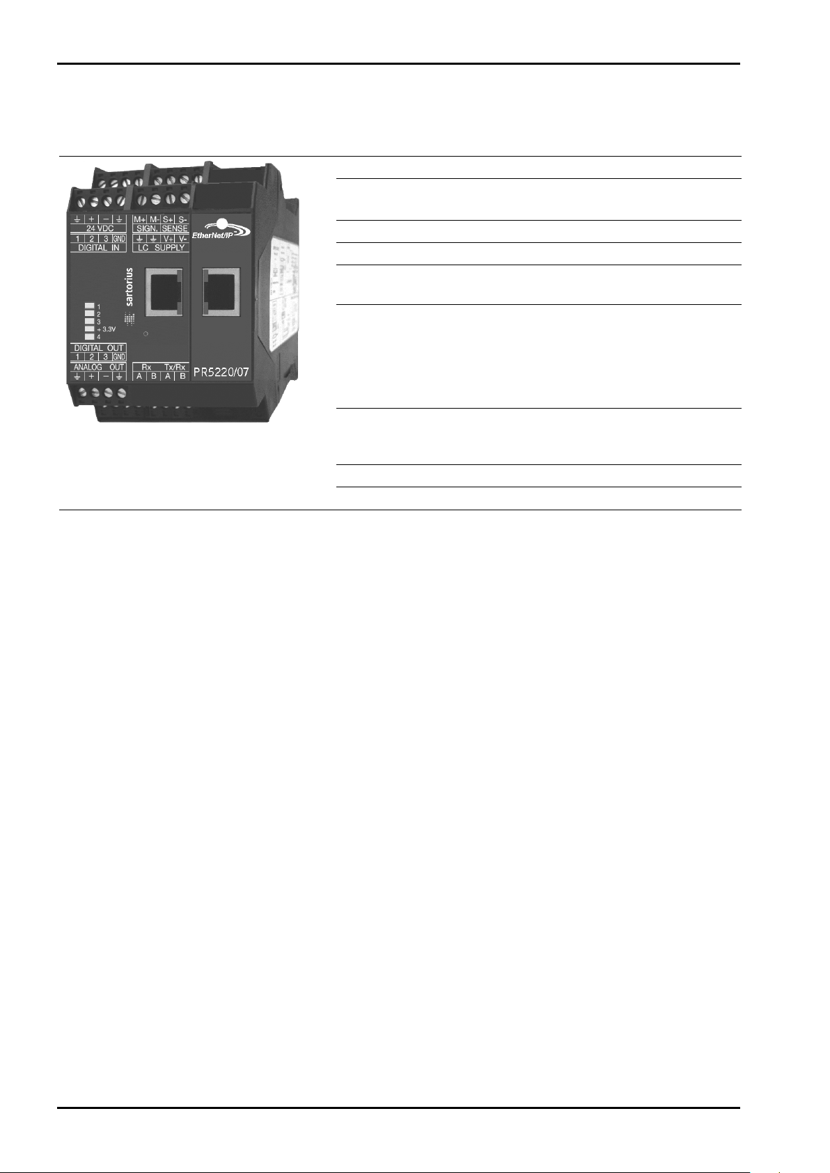
PR 5220/07 Ethernet Transmitter with EtherNet-IP
for PR 5220
Release: 2.10
Instrument Manual
Sartorius Mechatronics T&H GmbH, Meiendorfer Str. 205, 22145 Hamburg, Germany
9499 050 52201
Edition 6 08.07.2013
Tel:+49.40.67960.303 Fax:+49.40.67960.383

Please note
Any information in this document is subject to change without notice and does not represent a commitment on the part of
SARTORIUS unless legally prescribed. This product should be operated only by trained and qualified personnel. In correspondence
concerning this product the type, name and release number as well as all license numbers in relation to the product have to be
quoted.
Bitte beachten
Alle Angaben in diesem Dokument sind - soweit nicht gesetzlich vorgegeben - unverbindlich für SARTORIUS und stehen unter
Änderungsvorbehalt. Die Bedienung des Produktes darf nur von geschultem, fach- und sachkundigem Personal durchgeführt
werden. Bei Schriftwechsel über dieses Produkt bitte Typ, Bezeichnung und Versionsnummer sowie alle mit dem Produkt in
Zusammenhang stehenden Lizenznummern angeben.

PR 5220 Instrument Manual Table of Contents
1 Safety Information ...................................................................................................................................................................................... 7
2 Ethernet Transmitter Series .................................................................................................................................................................... 10
3 Installing the Instrument ........................................................................................................................................................................ 20
Table of Contents
1.1 General Information .................................................................................................................................................................................... 7
1.2 Intended Use .................................................................................................................................................................................................. 7
1.3 Initial Inspection ........................................................................................................................................................................................... 7
1.4 Before Commissioning ................................................................................................................................................................................ 7
1.4.1 Installation ........................................................................................................................................................................................ 8
1.4.2 Electrostatically Sensitive Components ................................................................................................................................... 8
1.4.3 Protective Earth ............................................................................................................................................................................... 8
1.4.4 Supply Voltage Connection ......................................................................................................................................................... 8
1.4.5 Failure and Excessive Stress ......................................................................................................................................................... 9
1.4.6 Fuse ...................................................................................................................................................................................................... 9
1.4.7 EMC-Compliant Installation ........................................................................................................................................................ 9
2.1 The Transmitter Versions .......................................................................................................................................................................... 10
2.1.1 PR 5220/00 Version ...................................................................................................................................................................... 10
2.1.2 PR 5220/01 ProfibBus .................................................................................................................................................................. 10
2.1.3 PR 5220/04 DeviceNet ................................................................................................................................................................. 10
2.1.4 PR 5220/06 ProfiNet I/O ............................................................................................................................................................. 10
2.1.5 PR 5220/07 EtherNet-IP ............................................................................................................................................................. 10
2.2 Overview of the Instrument ................................................................................................................................................................... 11
2.3 Label on the Housing ................................................................................................................................................................................ 12
2.4 Housing Dimensions .................................................................................................................................................................................. 12
2.5 Display and Controls ................................................................................................................................................................................. 13
2.5.1 Status LEDs ...................................................................................................................................................................................... 13
2.5.2 Operation Using the VNC Program ......................................................................................................................................... 14
2.6 Overview of Connections ......................................................................................................................................................................... 19
3.1 Connections ................................................................................................................................................................................................. 20
3.1.1 Network Port .................................................................................................................................................................................. 20
3.1.2 RS-485 Interface ........................................................................................................................................................................... 21
3.1.3 Analog Output ............................................................................................................................................................................... 25
3.1.4 Optocoupler Inputs ....................................................................................................................................................................... 26
3.1.5 Optocoupler Outputs ................................................................................................................................................................... 27
3.1.6 Load Cell Connection ................................................................................................................................................................... 28
3.1.7 Connecting Analog Platforms (CAP...) .................................................................................................................................... 31
3.1.8 Connecting xBPI Platforms (IS...) ............................................................................................................................................. 32
3.1.9 Connection of Digital Load Cells .............................................................................................................................................. 32
3.1.10 ProfiBus Interface (PR 5220/01 only) ..................................................................................................................................... 33
3.1.11 DeviceNet Interface (PR 5220/04 only) ................................................................................................................................. 34
3.1.12 ProfiNet I/O Interface (PR 5220/06 only) .............................................................................................................................. 35
3.1.13 EtherNet-IP Interface (PR 5220/07 only) .............................................................................................................................. 36
Sartorius EN-3

Table of Contents
4 Commissioning ........................................................................................................................................................................................... 37
PR 5220 Instrument Manual
4.1 Data Backup/Power Failure .................................................................................................................................................................... 37
4.1.1 CAL Switch ..................................................................................................................................................................................... 37
4.1.2 Factory Settings ............................................................................................................................................................................ 38
4.2 Switching on the Instrument ................................................................................................................................................................ 38
4.3 Configuration and Calibration .............................................................................................................................................................. 38
4.3.1 Connecting the Device to the Network and Finding out the IP address ................................................................... 38
4.3.2 Resetting the Instrument/Activating Network'DHCP' ...................................................................................................... 41
4.3.3 Searching the Instrument in the Network Using 'IndicatorBrowser' .......................................................................... 44
4.3.4 Operation Using the VNC Program ......................................................................................................................................... 45
4.3.5 Operation Using Internet Browser .......................................................................................................................................... 46
4.3.6 INFO Function ................................................................................................................................................................................ 48
4.3.7 Setup Function (VNC) ................................................................................................................................................................. 48
4.3.8 Setup Menu .................................................................................................................................................................................... 49
4.4 Calibration Weighing Point ‚Internal A’ ............................................................................................................................................. 55
4.4.1 Displaying Calibration Data ...................................................................................................................................................... 55
4.4.2 Selecting the Calibration Mode ............................................................................................................................................... 56
4.4.3 Determining the Maximum Capacity (Max) ........................................................................................................................ 57
4.4.4 Determining the Scale Interval ................................................................................................................................................ 59
4.4.5 Determining the Dead Load ...................................................................................................................................................... 60
4.4.6 Calibration with Weight (by Load) ......................................................................................................................................... 62
4.4.7 Calibration with mV/V Value [by mV/V] ................................................................................................................................ 63
4.4.8 Calibration with Load Cell Data (“Smart Calibration“) ..................................................................................................... 64
4.4.9 Subsequent Dead Load Correction ......................................................................................................................................... 65
4.4.10 Linearization .................................................................................................................................................................................. 65
4.4.11 Test Value Determination/Display ........................................................................................................................................... 66
4.4.12 Finishing/Saving the Calibration ............................................................................................................................................. 66
4.4.13 Parameter Input ............................................................................................................................................................................ 67
4.5 Calibrating an xBPI Scale ........................................................................................................................................................................ 70
4.5.1 xBPI Set-up for Serial Port ........................................................................................................................................................ 70
4.5.2 xBPI Scale Function ..................................................................................................................................................................... 71
4.5.3 xBPI Platform Configuration .................................................................................................................................................... 71
4.5.4 xBPI Scale Parameter .................................................................................................................................................................. 73
4.5.5 xBPI Parameter Tables ................................................................................................................................................................ 74
4.5.6 xBPI Setting Dead Load .............................................................................................................................................................. 77
4.5.7 xBPI Calibration with the User Weight ................................................................................................................................. 78
4.5.8 xBPI Calibration with Automatic Weight Detection ......................................................................................................... 79
4.5.9 xBPI Calibration with Default Weight ................................................................................................................................... 80
4.5.10 xBPI Calibration with Built-in Weight .................................................................................................................................. 82
4.6 Calibrating Digital Load Cells Type ‘Pendeo®’ .................................................................................................................................. 83
4.6.1 General Information .................................................................................................................................................................... 83
4.6.2 Viewing the Interfaces ................................................................................................................................................................ 83
4.6.3 Selecting and Setting up the Interface ................................................................................................................................. 83
4.6.4 Selecting the Load Cell Type ..................................................................................................................................................... 84
4.6.5 Adjustment Sequence ................................................................................................................................................................. 85
4.6.6 Search for Load Cells ................................................................................................................................................................... 85
4.6.7 Assigning Load Cells .................................................................................................................................................................... 87
EN-4 Sartorius

PR 5220 Instrument Manual Table of Contents
5 J-Bus/ModBus Protocol ........................................................................................................................................................................ 117
6 SMA Protocol ........................................................................................................................................................................................... 125
7 Fieldbus Interface ................................................................................................................................................................................... 134
8 Global SPM Variables ............................................................................................................................................................................. 145
9 Configuration Print-Out ....................................................................................................................................................................... 148
10 Extended Functions ................................................................................................................................................................................ 150
4.6.8 Calibrating Load Cells .................................................................................................................................................................. 88
4.6.9 Corner Correction ......................................................................................................................................................................... 91
4.6.10 Finishing/Saving the Calibration .............................................................................................................................................. 92
4.6.11 Parameter Input ............................................................................................................................................................................ 93
4.6.12 Subsequent Dead Load Correction .......................................................................................................................................... 95
4.7 Configuring General Parameters........................................................................................................................................................... 96
4.7.1 Serial Interfaces [Serial ports parameter] ............................................................................................................................. 96
4.7.2 Operating Parameters .................................................................................................................................................................. 98
4.7.3 Fieldbus Parameters ..................................................................................................................................................................... 99
4.7.4 Network Parameters .................................................................................................................................................................. 101
4.8 Configuring Limit Values ...................................................................................................................................................................... 102
4.9 Digital Outputs and Inputs .................................................................................................................................................................. 106
4.9.1 Configuring Digital Outputs ................................................................................................................................................... 106
4.9.2 Configuring Digital Inputs ...................................................................................................................................................... 108
4.10 Analog Output ......................................................................................................................................................................................... 110
4.10.1 Adapting the Analog Output ................................................................................................................................................. 111
4.11 Logfiles ....................................................................................................................................................................................................... 112
4.12 Saving Configuration Data [Backup of EAROM] ........................................................................................................................... 113
4.12.1 Saving Configuration and Calibration Data ...................................................................................................................... 113
4.12.2 Loading Configuration and Calibration Data into the Device ..................................................................................... 115
5.1 General Description ................................................................................................................................................................................ 117
5.2 ModBus-TCP/-UDP .................................................................................................................................................................................. 118
5.3 Functions ................................................................................................................................................................................................... 119
5.4 Error Messages ......................................................................................................................................................................................... 123
5.5 Word Addresses ....................................................................................................................................................................................... 124
6.1 General ....................................................................................................................................................................................................... 125
6.2 Description of Used Symbols ............................................................................................................................................................... 125
6.3 SMA Command Set ................................................................................................................................................................................. 126
6.4 SMA Reply Messages .............................................................................................................................................................................. 129
6.5 Communication Error ............................................................................................................................................................................ 134
7.1 Fieldbus Interface Protocol .................................................................................................................................................................. 134
7.2 Description of the I/O Area (Read / Write Window) .................................................................................................................... 136
7.3 Special hints for DeviceNet and EtherNet-IP ................................................................................................................................. 140
7.4 Fieldbus Register ..................................................................................................................................................................................... 141
10.1 Resetting the Instrument to the Factory Settings........................................................................................................................ 150
10.2 Updating a new Software with ‚FlashIt’ .......................................................................................................................................... 151
Sartorius EN-5

Table of Contents
11 Repairs and Maintenance ..................................................................................................................................................................... 153
12 Disposal ...................................................................................................................................................................................................... 153
13 Error Messages ......................................................................................................................................................................................... 154
14 Specifications ........................................................................................................................................................................................... 159
15 Index ............................................................................................................................................................................................................ 163
16 Appendix .................................................................................................................................................................................................... 166
PR 5220 Instrument Manual
11.1 Solder Work ............................................................................................................................................................................................... 153
11.2 Cleaning ..................................................................................................................................................................................................... 153
13.1 Measuring Circuit Error Messages ..................................................................................................................................................... 154
13.2 Weight Error Status ................................................................................................................................................................................ 155
13.3 Error Messages with xBPI Scales ........................................................................................................................................................ 155
13.4 Error messages of the Calibration ...................................................................................................................................................... 156
13.5 Show Error Log ......................................................................................................................................................................................... 158
14.1 Instructions for Use of 'Free Software' ............................................................................................................................................ 159
14.2 General Data ............................................................................................................................................................................................. 160
14.2.1 Power Supply ............................................................................................................................................................................... 160
14.3 Effect of Ambient Conditions ............................................................................................................................................................. 160
14.3.1 Environmental Conditions ....................................................................................................................................................... 160
14.3.2 Electromagnetic Compatibility (EMC) ................................................................................................................................. 160
14.3.3 RF Interference Suppression ................................................................................................................................................... 160
14.4 Weighing Electronics ............................................................................................................................................................................. 161
14.4.1 Load Cells ...................................................................................................................................................................................... 161
14.4.2 Principle ........................................................................................................................................................................................ 161
14.4.3 Accuracy and Stability .............................................................................................................................................................. 161
14.4.4 Sensitivity ..................................................................................................................................................................................... 161
14.5 Mechanical Data ...................................................................................................................................................................................... 162
14.5.1 Construction ................................................................................................................................................................................ 162
14.5.2 Dimensions ................................................................................................................................................................................... 162
14.5.3 Weight ........................................................................................................................................................................................... 162
14.6 Use in Legal-for-Trade Mode .............................................................................................................................................................. 162
14.6.1 Documentation for Verification on the Enclosed CD ..................................................................................................... 162
14.6.2 Additional Instructions ............................................................................................................................................................. 162
16.1 Pin Assignment for Interface RS-485 ............................................................................................................................................... 166
16.2 Network Settings under Windows XP ............................................................................................................................................... 167
16.3 Network Settings under Windows 7 ................................................................................................................................................. 168
EN-6 Sartorius

PR 5220 Instrument Manual Safety Information
1 Safety Information
1.1 General Information
The instrument was in perfect condition with regard to safety features when it left the
factory. To maintain this condition and to ensure safe operation, the operator must follow
the instructions and observe the warnings in this manual.
1.2 Intended Use
The instrument is intended for use as an indicator for weighing functions. Product operation, commissioning
and maintenance must be performed by trained and qualified personnel who are aware of and able to deal
with the related hazards and take suitable measures for self-protection.
The instrument reflects the state of the art. The manufacturer does not accept any liability for damage caused
by other system components or due to incorrect use of the product.
1.3 Initial Inspection
Check the content of the consignment for completeness and inspect it visually for signs of damage that may
have occurred during transport. If there are grounds for rejection of the goods, a claim must be filed with the
carrier immediately and the Sartorius sales or service organization must be notified.
1.4 Before Commissioning
Visual inspection:
Before commissioning and after and storage or transport, inspect the instrument visually
for signs of mechanical damage.
Sartorius EN-7

Safety Information
The supply voltage is 24V DC +10% / -15%.
PR 5220 Instrument Manual
1.4.1 Installation
The instrument is designed for mounting on standard rails (35 mm, acc. to DIN 46277).
Caution!
Excessive heat may reduce the instrument lifetime!
When mounting on the rail, make sure that the distance from other instruments left
and right of the module is at least 20 mm.
1.4.2 Electrostatically Sensitive Components
This instrument contains electrostatically sensitive components. For this reason, an equipotential bonding
conductor must be connected when working on the open instrument (antistatic protection).
1.4.3 Protective Earth
Connection to protective earth must be performed via the mounting rail.
1.4.4 Supply Voltage Connection
Max. power consumption of
- PR 5220/00: 6.5 W
- PR 5220/01: 8.5 W
- PR 5220/04: 8.5 W
- PR 5220/06: 8.5 W
- PR 5220/07: 8.5 W
For connection to 230/115 V AC, an external power supply
EN-8 Sartorius
(e.g. Sartorius PR 1624/00 or Phoenix Mini Power) is required.
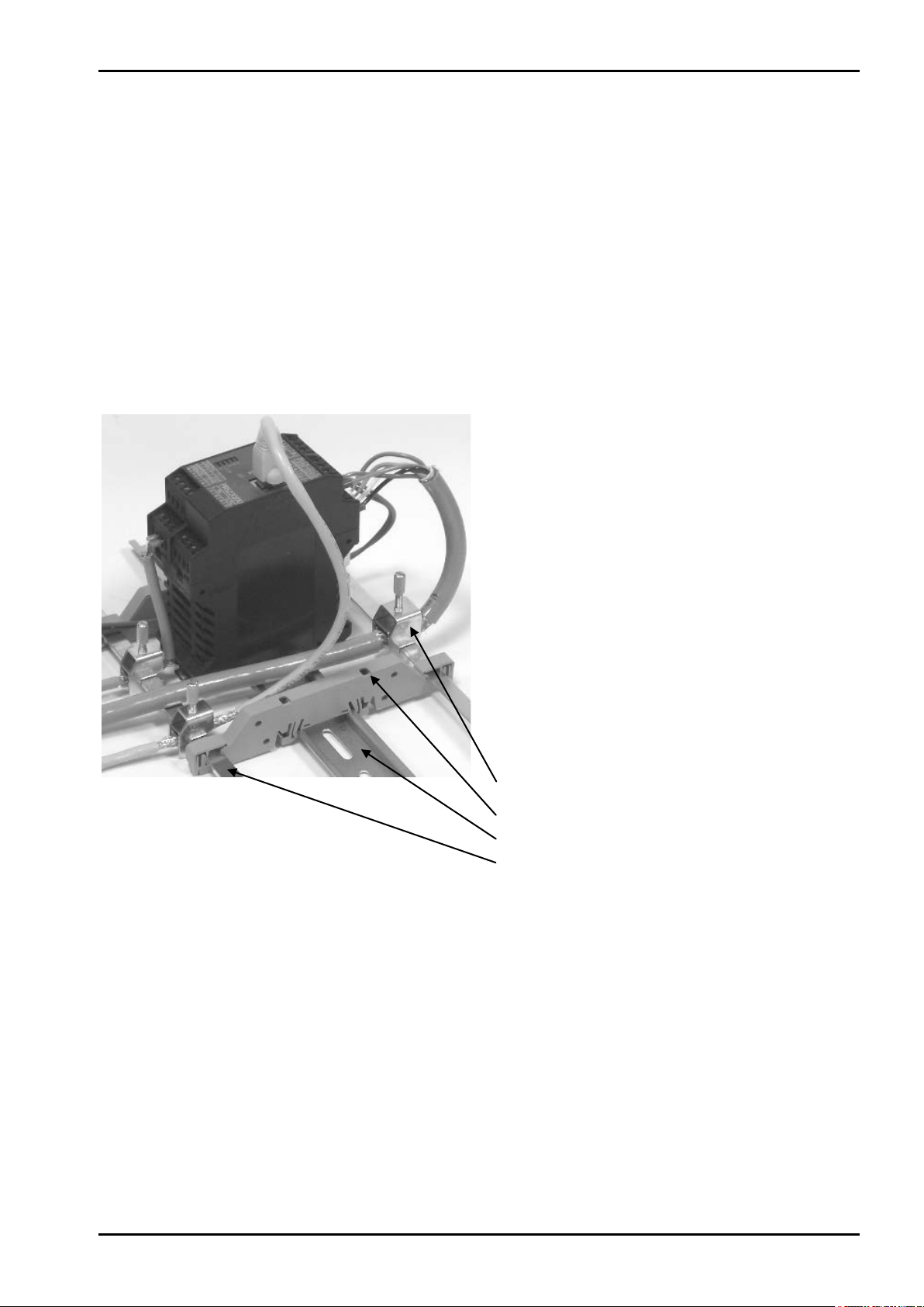
PR 5220 Instrument Manual Safety Information
Screen clamp (e.g. Phoenix SK8-D)
Rail connection (e.g. Phoenix AB-SK 65D)
Mounting rail (35 mm)
Screen rail (e.g. Phoenix NLS-CU 3/10)
1.4.5 Failure and Excessive Stress
If there is any reason to assume that safe operation of the instrument is no longer ensured, shut it down and
make sure it cannot be used. Safe operation is no longer ensured if any of the following is true:
- The instrument is physically damaged
- The instrument does not function
- The instrument has been subjected to stresses beyond the tolerance limits (e.g., during storage or
transport).
1.4.6 Fuse
This instrument does not have a replaceable fuse. The load cell supply voltage is protected against short circuit.
In case of failure of the load cell supply voltage, disconnect the instrument from the supply voltage, determine
the cause and take remedial measures. Subsequently, the supply voltage can be switched on again.
1.4.7 EMC-Compliant Installation
- Use only screened data cables.
- Connect screens on both ends with ground.
- Keep unscreened cable ends short.
- Connect screen rail to cabinet / housing with
low impedance.
- Use metal or metallized connector housings.
- Establish equipotential bonding between
instruments / system modules (Mandatory for
Ex-applications).
- Use standard reference potential.
- Connect mounting rail to protective earth.
- Install measure and data cables separately from
power cables.
Sartorius EN-9

Ethernet Transmitter Series
PR 5220 Instrument Manual
2 Ethernet Transmitter Series
2.1 The Transmitter Versions
Three PR 5220 series transmitter versions are available; subsequent extension of the version is not possible.
The version is determined unambiguously by the type number. The front foils are adapted to the version.
PR 5220/00 PR 5220/01 PR 5220/04
PR 5220/06 PR 5220/07
2.1.1 PR 5220/00 Version
This version has digital inputs and outputs as well as an analog output and a LAN adaptor for configuration
and operation of the instrument. Connecting e.g. a remote indicator is possible via the serial output.
2.1.2 PR 5220/01 ProfibBus
In addition to PR 5220/00, the instrument is provided with a ProfiBus port.
2.1.3 PR 5220/04 DeviceNet
In addition to PR 5220/00, the instrument is provided with a DeviceNet port.
2.1.4 PR 5220/06 ProfiNet I/O
In addition to PR 5220/00, the instrument is provided with a ProfiNet I/O port.
2.1.5 PR 5220/07 EtherNet-IP
In addition to PR 5220/00, the instrument is provided with a EtherNet-IP port.
EN-10 Sartorius

PR 5220 Instrument Manual Ethernet Transmitter Series
Accuracy 10,000 e @ 6 samples/sec
2.2 Overview of the Instrument
-
- Internal resolution: 7.5 million counts
- Linearity: < 0.002%
- Sampling rate: 6 ... 100/sec selectable
- Digital filter with selectable characteristic
- Electrically isolated interfaces
- 3 programmable pairs of limit values
- 24 VDC supply voltage connection
- Connection using plug-in terminal blocks
- Socket for LAN adaptor
- The instrument is provided for snap-on mounting on a standard
rail.
- 5 status LEDs für supply voltage, communication, error detection
Calibration and configuration of the instrument are menu guided using a PC.
- Calibration with weight, using the mV/V method or with load cell
data (“smart calibration”)
- 0/4 ... 20 mA analog output, configurable for gross/net weight
- Analog value via fieldbus
- 3 digital input channels, electrically isolated
- 3 digital output channels, electrically isolated
Communication protocols
For the internal RS-485:
- Remote display protocol
- SMA protocol
- xBPI protocol
For the internal LAN:
- ModBus-TCP
- Ethernet-TCP/IP
- OPC
Fieldbus slave:
- PR 5220/01 ProfiBus-DP
- PR 5220/04 DeviceNet
- PR 5220/06 ProfiNet I/O
- PR 5220/07 EtherNet-IP
Sartorius EN-11

Ethernet Transmitter Series
2.3 Label on the Housing
A label with the wiring diagram is located on one side of the instrument:
2.4 Housing Dimensions
PR 5220 Instrument Manual
PR 5220/00 PR 5220/01, -/04, -/06, -/07
EN-12 Sartorius

PR 5220 Instrument Manual Ethernet Transmitter Series
Power on
Bus
Bus connection not provided
Standstill
Center zero
Below zero or above max. capacity
lit
lit
lit
Note:
2.5 Display and Controls
2.5.1 Status LEDs
The instrument has 5 green LEDs for display of the operating or error status.
2.5.1.1 Power Supply, Bus Connection
lit
* The LED for the bus activity (PR 5220/01 a. PR 5220/04) is lit as soon as there is a connection. It continues
being lit, also when there is no communication, or when the physical connection is cut.
lit * blinks 1 Hz
2.5.1.2 Weight Status Indicator
The weight error status sees in Chapter 13.2.
Sartorius EN-13

Ethernet Transmitter Series
Display
Function keys
Alphanumeric keys
Softkeys
Indicator keys
Navigation/menu keys
2.5.2 Operation Using the VNC Program
2.5.2.1 Operator Interface
PR 5220 Instrument Manual
EN-14 Sartorius

PR 5220 Instrument Manual Ethernet Transmitter Series
Available mass units are mg, g, kg, t, lb or oz.
The display shows weight values of up to 7 digits with decimal point and plus or minus sign.
lb and oz units are not permitted for use in legal
metrology in the EU and EEC.
The weight readout shows the current weight on a
bar graph that indicates proportion of the
maximum capacity (Max), with 0 on the left and
100 % on the right.
2.5.2.2 Status Symbols
The following status symbols can be shown:
Symbol Description
Gross weight (Brutto)
Gross weight in NTEP or NSC mode
, Tare weight, fixtare
Net weight (Net = gross – Tare)
The display shows the test value without mass unit
Positive value
Negative value
The weight value is within ±¼ d of zero
The weight value is stable.
Value not permissible in legal metrology (e.g., 10-fold resolution).
Range 1
Range 2
Range 3
Sartorius EN-15

Ethernet Transmitter Series
PR 5220 Instrument Manual
2.5.2.3 Keys
The following tables show the basic meanings of symbols on the operator interface.
Indicator key Description
Display gross weight
Display tare weight
Taring; the current gross weight is stored in the tare memory, provided that:
- weight value is stable.
- instrument is not in error status (function dependent on configuration).
Sets gross weight to zero, provided that (function dependent on configuration):
- weight value is stable.
- weight is within zero setting range
Start printing.
Navigation key Description
Cursor moves to the right.
Menu key Description
Selection
Cursor moves to the left.
Selection
Scroll up in the menu.
Scroll down in the menu.
Softkey: select function
Backspace/delete
Exit from current menu; continue operation on next higher level.
Enter/confirm
EN-16 Sartorius

PR 5220 Instrument Manual Ethernet Transmitter Series
Setup
Config
Calib
Param
Function key Description
Information on version number, fitted hardware,10-fold resolution
Without function
Test
Open the setup menu
Toggle to alphabetic input mode.
2.5.2.4 Operation Using Softkeys
During configuration, you can switch between the mass units by pressing this key.
The functions of the five softkeys below the graphic display are indicated in the bottommost text line of
the display. Softkey functions shown in gray are not available on the active menu level, or not with the active
access privileges.
When operating steps involving softkeys are described in this manual, the softkey labels are shown in square
brackets, rather than in graphics of the softkeys.
Sartorius EN-17

Ethernet Transmitter Series
Info
Show status
Show HW-slots
Weighingpoint/WP A/Calibration
Digital filter
off
Test mode
absolute
W & M
none
Standstill time
0.50 s
Standstill range
1.00 d
Weighingpoint/WP A/Calibration
2.5.2.5 Selection Using the Navigation Keys
Press to scroll down, or to scroll up in a menu.
PR 5220 Instrument Manual
Press
Press
An arrow
pressing
If the list of menu items is long, a vertical bar graph on the left (black and gray) shows which part of the list is
displayed.
to select a menu item. To select the desired setting for the selected menu item, press .
to exit the menu and continue the operation on the next higher level.
in front of a menu item indicates that there are menu sublevels. The menu item selected by
is shown inversely.
Show version
Measuretime
320 ms
Press
to select an item.
Availability of additional settings options selectable with is indicated by preceding double arrows .
Measuretime
640 ms
Press
to select the measuring time.
EN-18 Sartorius
PR 5220 Instrument Manual Ethernet Transmitter Series
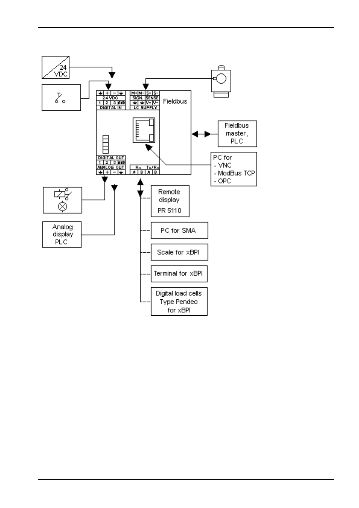
2.6 Overview of Connections
Sartorius EN-19

Installing the Instrument
Connection
Remote operation of the instrument from the notebook/PC is
PR 5220 Instrument Manual
3 Installing the Instrument
• Before starting work, please read Chapter 1 and follow all instructions.
Further procedures:
• Check the consignment: unpack the components specific to the application.
• Safety check: inspect all components for damage.
• Make sure the on-site installation is correct and complete including cables, e.g. power cable fuse
protection, load cells, cable junction box, data cable, console/cabinet, etc.
• Follow the instructions for installation of the unit relating to application, safety, ventilation, sealing and
environmental influences.
• Connect the cable from cable junction box or platform/load cell.
• If applicable: connect other data cables, network cables, etc.
• Connect the instrument to the supply voltage.
• Check the installation.
3.1 Connections
3.1.1 Network Port
The network port is built in as standard equipment. The port contains powerful TCP/IP connection circuitry
with transfer rates of 10 or 100 Mbit/sec. The LEDs on the connector (RJ-45) indicate whether the port is
functioning.
Transfer rate
Connection method
Cable
Cable impedance
Electrical isolation
possible; install VNC program version 3.3.7* on the
notebook/PC. For setting the network address, see
Chapter
* Sartorius guarantees the functionality only if this version is
used!
10 Mbit/sec, 100 Mbit/sec,
full/half duplex, auto-detection
Point to point
CAT 5 patch cable, shielded twisted pair
150 ¥
yes
RJ-45 socket on top of housing
4.3.3.
EN-20 Sartorius

PR 5220 Instrument Manual Installing the Instrument
3.1.2 RS-485 Interface
The interface is intended for connecting a remote display, a PC for data transmission using the SMA protocol
or scale/terminal/digital load cells, type Pendeo for data transmission using the xBPI protocol.
Connection method
Number of channels/type
Transfer rate (Bits/s)
Bits/stop bits
Parity
Signals
Electrical isolation
Cable length
Cable type
<...> = default settings (factory settings)
4-pin plug-in terminal block
1 RS-485, full/half duplex
300, 600, 1200, 2400, 4800, <9600>, 19200
<8/1> or 7/1
<even>, <odd>, <none>
RxA (R-), RxB (R+), TxA, TxB
yes
max. 1000 m
Shielded twisted pair (e.g. LifYCY 2x2x0.20)
Sartorius EN-21
Installing the Instrument
Note:
ON:
S1, S2, S3
ON:
S2
OFF:
S4, S5
OFF:
S1, S3,
S4 is not relevant!
PR 5220 Instrument Manual
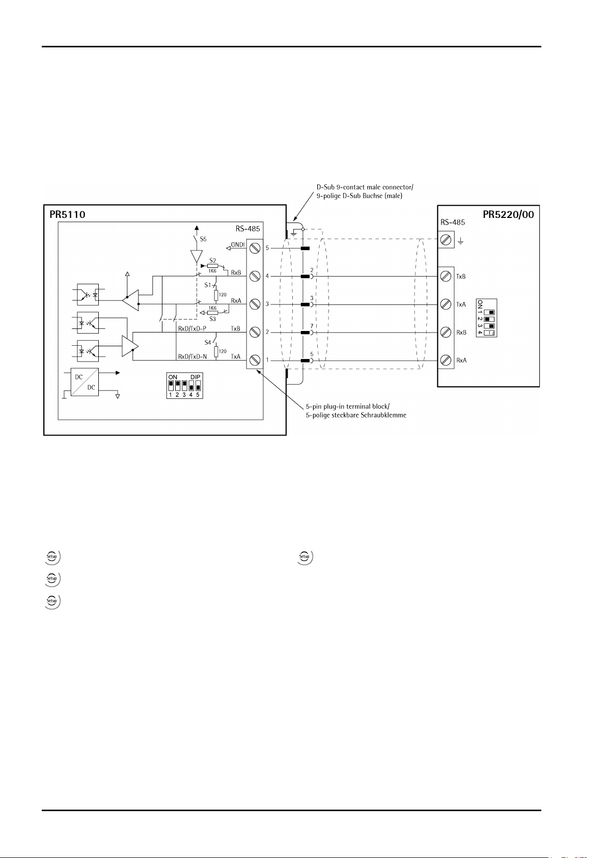
3.1.2.1 Connecting of a PR 5110 Remote Display
Four-wire transmission, point to point, full duplex (simultaneous sending and receiving possible) with
PR 5110 remote display.
When replacing PR 1627/PR 1628 with PR 5110, note that the pin assignment must be
attended, see Chapter 16.1.
Description see instrument manual PR 5110.
Switch settings Switch settings
Configuration PR 5110 Configuration PR 5220/00
- - –
- [Serial ports parameter]-[Remote display][Builtin RS485]
- – -
[Param]: [Mode]-[single transmitter]
- – -
The following operations are possible from the connected remote display:
- Switch over to another weighing point
- Indicate current value type
- Set tare
- Reset tare
- Set zero
- Start Print
EN-22 Sartorius

PR 5220 Instrument Manual Installing the Instrument
ON:
S1, S3
OFF:
S2 S4 is not relevant!
ON:
S1, S3
OFF:
S2 S4 is not relevant!
3.1.2.2 Connection of a xBPI Platform
Switch settings
Configuration PR 5220
-[Serial ports parameter]-[xBPI-Port]-[Builtin RS485]
3.1.2.3 Connection of a xBPI terminal
Switch settings
Configuration PR 5220
Sartorius EN-23
-[Serial ports parameter]-[xBPI-Port]-[ Builtin RS485]
Installing the Instrument
ON:
S1, S3
OFF:
S2 S4 is not relevant!
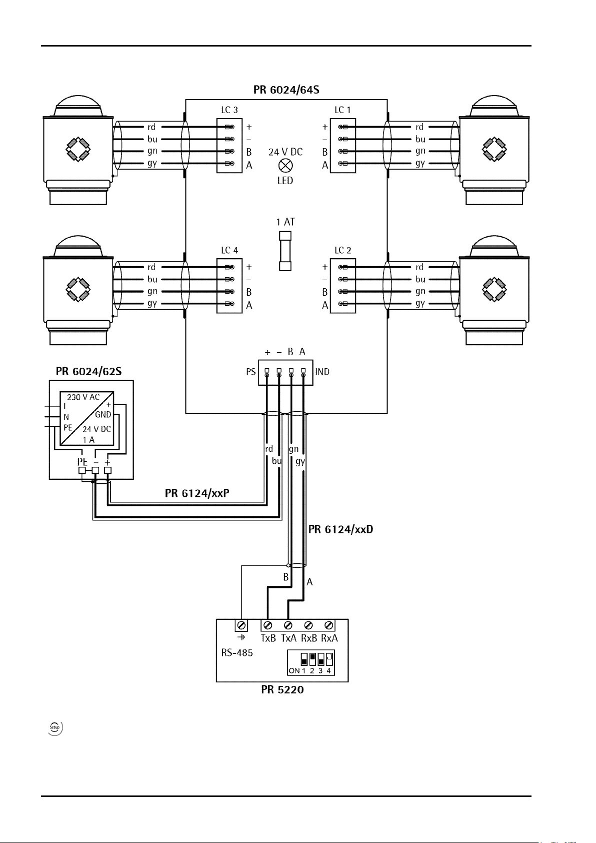
3.1.2.4 Connecting 4 Digital Load Cells Type ‚Pendeo®‘
PR 5220 Instrument Manual
Switch settings
Configuration PR 5220
-[Serial ports parameter]-[xBPI-Port]-[ Builtin RS485]
EN-24 Sartorius
PR 5220 Instrument Manual Installing the Instrument
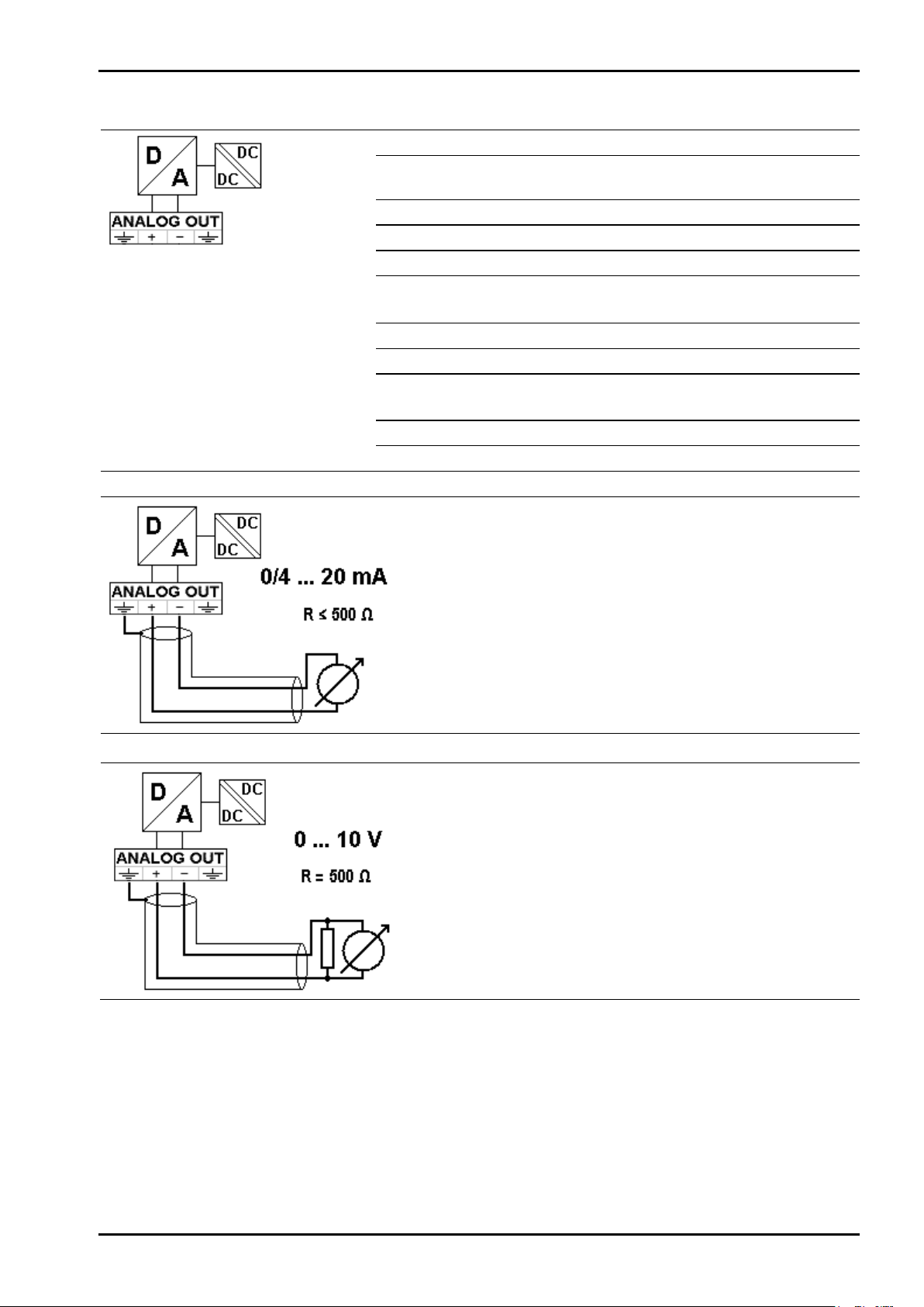
3.1.3 Analog Output
Connection method
Number of outputs
Output
Range
Resolution
Linearity error
Temperature effect
Load
Protected against short
circuit
Electrical isolation
Cable length (shielded)
4-pin plug-in terminal block
1 current output,
output voltage via external resistor
Gross, net weight or via ProfiBus
0/4 ... 20mA, configurable
e.g. 0 - 20 mA in max. 40,000 counts
@ 0 - 20mA: <0,05 %
@ 4 - 20 mA: <0,025 %
<100 ppm/K
0 ... max. 500 ¥
yes
yes
150 m (current output)
0/4…20mA
Analog signal,
current output
The current is supplied directly via
the terminals.
0…10V
Analog signal,
voltage output
The voltage level corresponds to the
voltage drop across the 500 ¥
(10 ppm/K) resistor.
Sartorius EN-25

Installing the Instrument
PR 5220 Instrument Manual
3.1.4 Optocoupler Inputs
The 3 optocoupler inputs have one common potential (GND) for the input group that is separated from the
common potential of the output group.
Example: contact input connection
Connection method
Cable
Number of outputs
Input signal
Input voltage
Input current
Electrical isolation
When a voltage ≥10 V DC is applied to the terminals (in the
example:1-GND), input 1 is active (true).
4-pin plug-in terminal block
Shielded, max. 50 m
3
External supply required
10…28 V DC for 'high' level
0…5 V DC for 'low' level
Max. 28 V DC
<11 mA @ 24 V DC
<5 mA @ 12 V DC
Yes; a common minus potential for the group
of 3 inputs
EN-26 Sartorius

PR 5220 Instrument Manual Installing the Instrument
When output 1 is active (true), the relay switches.
When output 1 is active (true), the output voltage
3.1.5 Optocoupler Outputs
The 3 optocoupler outputs have one common potential (GND) for the output group that is separated from the
common potential of the input group.
Example: relay control connection
Connection method
Cable
Number of outputs
Output signal
Output current
Output voltage
Electrical isolation
For protection of the output circuit, relays with
free-wheel diode must be provided.
4-pin plug-in terminal block
Shielded, max. 50 m
3
External supply required
Max. 30 mA
Max. switching voltage: 28 VDC
Yes; a common minus potential for the group
of 3 outputs
Example: voltage output connection
changes from 24/12 V DC into <3 V DC.
A load resistance of 2.2/1 k¥ must be provided.
Sartorius EN-27

Installing the Instrument
The cable colors shown in this chapter are applicable to the Sartorius PR 62XX series load cells.
PR 5220 Instrument Manual
3.1.6 Load Cell Connection
Before connecting other types, carefully follow the information related to the assignment of
load cell/platform cable colors.
• The distance between the measuring cables and the power cables should be at least 1 m.
• The measuring cables should be laid in separate cable conduits or steel pipes connected to earth potential.
• Power cables should be crossed at right angles.
Load cell supply circuit
The load cell supply voltage is fixed to 12 V DC and protected against short circuit.
Load resistance of load cells ≥75 ¥, e.g. 8 load cells of 650 ¥ each.
3.1.6.1 Connection Using 6-Wire Technology
See also label on the housing outside (Chapter 2.3) and manual of the junction box.
Terminal Description
SIGN. M+
SIGN. MSENSE S+
SENSE SLC SUPPLY V+
LC SUPPLY V-
+ signal/LC output
- signal/LC output
+ sense
- sense
+ supply/excitation
- supply/excitation
3.1.6.2 Connection of a Load Cell in 4-Wire Technology
Note that links between SENSE S+ and LC SUPPLY V+ and between SENSE S- and LC SUPPLY V- directly at the
transmitter must be provided.
Terminal Description
SIGN. M+
SIGN. MSENSE S+
SENSE SLC SUPPLY V+
LC SUPPLY V-
+ signal/LC output
- signal/LC output
+ sense
- sense
+ supply/excitation
- supply/excitation
3.1.6.3 Connecting PR 6221 Load Cells
See installation manual PR 6221 and PR 6021/08, -/68.
EN-28 Sartorius

PR 5220 Instrument Manual Installing the Instrument
Testing the Measuring Circuit
A simple test with the load cells connected can be carried out with a multimeter
(not with external supply or intrinsically safe load cell interface):
Supply voltage
12 V ±0,8 V
(symmetrical to housing GND)
Sense voltage
12 V ±0,8 V
(symmetrical to housing GND)
Measuring voltage
Measuring voltage
0 - 12 mV @ WZ mit 1,0 mV/V
0 - 24 mV @ WZ mit 2,0 mV/V
0 V ±0,5 V
Sartorius EN-29

Installing the Instrument
PR 5220 Instrument Manual
3.1.6.4 External Load Cell Supply
The internal load cell supply voltage of PR 5220 (V+, V-) is not connected.
The common line of the symmetrical external supply must be connected to the same terminal of PR 5220 as
the shield of the load cell/extension cable.
Specification of external supply: ±6 V DC +5 %, -30 %; max ripple. 50 mVpp; max. asymmetry ±3 %.
An external supply voltage smaller than 8 V DC (±4 V DC) must be set under
[Calibration]-[Param]-[External supply].
-[Weighingpoint]-[WP A]-
3.1.6.5 Connection via Intrinsically Safe Interface PR 1626/60
Connect the instrument to PR 1626/60 as described below. For additional connections, refer to the PR 1626/60
instrument manual. The internal load cell supply voltage of PR 5220 (V+, V-) is not connected.
Note:
If MX8 is closed in PR 1626/60,
[below 8 V DC] must be set under
-[Weighingpoint]-[WP A]-[Calibration]-
[Param]- [External supply].
EN-30 Sartorius

PR 5220 Instrument Manual Installing the Instrument
Platform with 6-wire connection
Platform with 4-wire connection
Platforms with 4-wire connection require following
Caution!
3.1.7 Connecting Analog Platforms (CAP...)
One Combics analog platform (CAP... series) can be connected to the instrument.
The following example shows a platform with 6-wire connection and another one with 4-wire connection.
links:
- between +V and +S
The cable colors shown above are valid for a CAPP4 500 x 400 and a CAPP1 320 x 420,
as an example.
The assignments of cable colors are given in the platform operating manual.
Pin allocation Combics 1…3-instruments Pin allocation PR 5220
BR_POS V+ LC SUPPLY
SENSE_POS S+ SENSE
OUT_POS M+ SIGN.
OUT_NEG M- SIGN.
SENSE_NEG S- SENSE
BR_NEG V- LC SUPPLY
Connect the cable screens with the ground terminal of the instrument. If the measuring leads (+M, -M) are
screened individually, these screens must also be connected to the ground terminal (see also Chapter 1.4.7).
- between –V and –S
Sartorius EN-31

Installing the Instrument
3.1.8 Connecting xBPI Platforms (IS...)
One xBPI platform (IS... series) can be connected to the instrument.
PR 5220 Instrument Manual
Connection to a RS-485 interface, see Chapter 3.1.2.2.
3.1.9 Connection of Digital Load Cells
Digital load cells can be connected to the device via xBPI port and RS-485 interface.
Connection to an RS-485 interface, see Chapter 3.1.2.4.
EN-32 Sartorius

PR 5220 Instrument Manual Installing the Instrument
3.1.10 ProfiBus Interface (PR 5220/01 only)
Communication protocols and syntax comply with the ProfiBus-DP standard to IEC 61158 with transfer rates
up to 12 Mbit/s.
Transfer rate
Protocol
Configuration
Cable
Cable impedance
Certificates
Electrical isolation
Cable length
Connection to the ProfiBus is using the 9-contact plug-in socket on the front panel.
9.6 kbit/s to 12 Mbit/s,
baud rate auto-detection
PR OFIBUS-DP-V0 slave
to EN 50 170 (DIN 19245),
mono or multi-master systems are
supported. Master and slave devices,
max. 126 nodes possible.
Watchdog timer
GSD file (‚SART5220.gsd’ stored on the
CD in directory ‘Fieldbus’)
Special ProfiBus color: violet
Shielded twisted pair cable
150 ¥
ProfiBus test center Comdec in
Germany and PNO (ProfiBus User
Organization).
Suitable for industrial applications to
CE, UL and cUL
Optocoupler in lines A and B (RS-485)
Max. distances 200 m can be extended
with 1.5 Mbit/s by means of additional
repeater
The transmitter is the only
or last slave on the bus
The transmitter is not the only
or last slave on the bus
PIN Signal
3
4
5
6
8
RxD/TxD-P
CNTR-P
DGND
VP
RxD/TxD-P
Sartorius EN-33

Installing the Instrument
PR 5220 Instrument Manual
3.1.11 DeviceNet Interface (PR 5220/04 only)
It is a complete DeviceNet adapter (SLAVE) with CAN controller and transfer rates of up to 500 kbit/s.
Connection
Transfer rate
Topology
Protocol
Configuration
Certificates/
conformity
Cable
Cable impedance
Bus termination
Bus load
Electrical isolation
5-contact screw terminal block (plug-in)
125, 250 and 500 kbit/s
Parallel bus
DeviceNet master/slave
Polling method (polled I/O)
CRC error detection
to IEC 62026 (EN50325)
Max. 64 station nodes
Max. data width 512 bytes input & output
EDS file (‚sag_5220.eds’ stored on the CD in
directory ‘Fieldbus’)
MAC-ID (1…62)
Compatible with DeviceNet specification
Vol 1: 2.0, Vol 2: 2.0
ODVA certificate in accordance with
conformity test software version A-12
Suitable for industrial applications to CE,
UL and cUL
DeviceNet, color: petrol-green
2x 2 shielded twisted pair
150 ¥
120 ¥ at the cable ends
30 mA @ 24 V DC
Yes, optocoupler and DC/DC converter
Connecting diagram for a master with three slaves
EN-34 Sartorius

PR 5220 Instrument Manual Installing the Instrument
W
3.1.12 ProfiNet I/O Interface (PR 5220/06 only)
It is a complete ProfiNet I/O interface (SLAVE). It contains a powerful UDP/IP connecting circuitry with transfer
rates of 10 and 100 Mbits/s.
Note:
Connection
Transfer rate
Connection mode
Protocol
Configuration
Certificate
Cable
Cable impedance
Potential isolation
Recommendation for e.g. Siemens S7
Fieldbus slave setting:
Use DHCP [on] as default and activate the master as a DHCP server
(
[assign IP Adr via IO controller]).
RJ-45 connecting socket
10 Mbit/sec and 100 Mbit/sec
Autodetection (10/100, HalfDX/FullDX)
Network
ProfiNet I/O
XML file (‚GSDML-xxx-Sartorius-PR5220-
xxx.xml’ stored on the CD in directory
‘Fieldbus’)
ProfiBus Nutzerorganisation e.V.
for HMS Industrial Networks AB
Certificate no.: Z10006
Report: PN005-1, 12.02.2007
Twisted pairs, screened,
e.g. patch cable CAT5
Autolink (straight oder crossover
150 ¥
Yes
Slave – master device names
A unique device name must be assigned out of the master. This name is given highest priority
when establishing the communication.
When changing instruments/servicing, please note:
Apart from the IP address, the device name must correspond to the one of the replacement
device. Explicit assignment out of the master is required.
Example:
Sartorius EN-35
Installing the Instrument
PR 5220 Instrument Manual
3.1.13 EtherNet-IP Interface (PR 5220/07 only)
It is a complete EtherNet-IP adapter (SLAVE). It contains a powerful TCP/IP and EtherNet-IP connecting
circuitry with transfer rates of 10 and 100 Mbits/s.
Connection
Transfer rate
Network Connection mode
Protocol
Configuration
Certificates/
conformity
Cable
Cable impedance
Electrical isolation
RJ-45 connecting socket
10 Mbit/sec and 100 Mbit/sec
Autodetection (10/100, HalfDX/FullDX)
EtherNet-IP
EDS file (‚sag_5220_ethernetip.eds’ stored
on the CD in directory ‘Fieldbus’)
ODVA für HMS Industrial Networks AB
Product code: 99
Product name: Anybus-CC EtherNet/IP
SOC file name: ABCC_EIP_205_2.stc
17.04.2009
Twisted pairs, screened,
e.g. patch cable CAT5
Autolink (straight oder crossover)
150 ¥
Yes
EN-36 Sartorius
PR 5220 Instrument Manual Commissioning
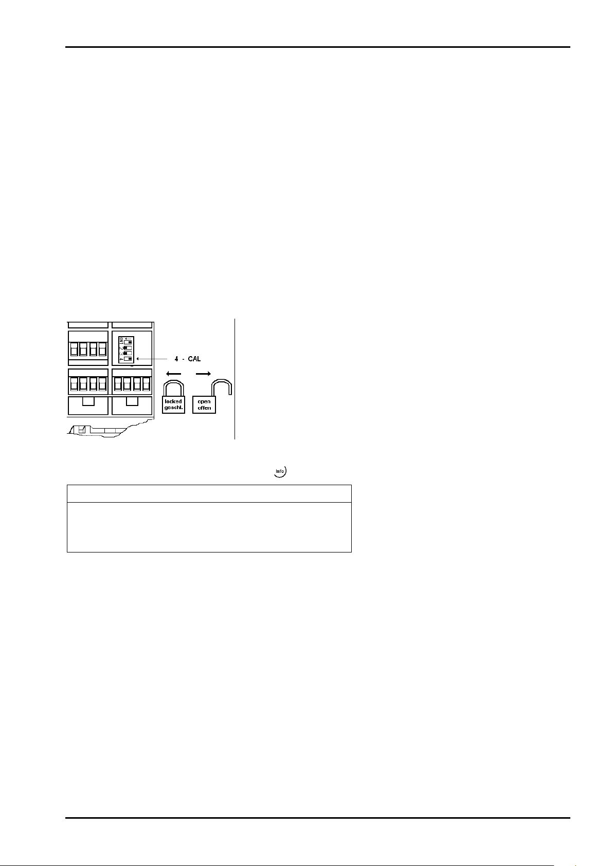
The CAL switch is located under a cover that can be opened by means
Info/Status
Free system RAM
4128 of 15184 kb
Cal-Switch
opened
[opened] = opened; no write protection
[closed] = closed; write protection is active
4 Commissioning
The meaning of indicator LEDs is described in Chapter 2.5.
4.1 Data Backup/Power Failure
The calibration data and parameters as well as all configuration and interface data are stored in a
non-volatile (EAROM) memory. Unauthorized data changing can be prevented by an access code. Additional
write protection is provided for calibration data and parameters (CAL switch, see Chapter 4.1.1).
In case of power failure, all entered data and parameters remain unchanged.
4.1.1 CAL Switch
The CAL switch protects the calibration data and parameters against unauthorized access.
When the CAL switch is in 'open' position, the calibration data and parameters can be changed using the
PC program or via the ProfiBus connection.
With the CAL switch in the 'closed' position, the calibration data (e.g. dead load, Span) and Parameters (e.g.
measure time, zero tracking etc.) cannot be changed.
of a knife.
For ’legal-for-trade’ applications, set the CAL switch (4) to the left
position (ON) and seal the cover.
To view the position of the CAL switch, select
-[Show status]:
Sartorius EN-37

Commissioning
PR 5220 Instrument Manual
4.1.2 Factory Settings
Calibration data <default> Calibration data <default>
Full scale (Max) <3000> <Kg> Measure time (M) <320>ms
Scale interval <1> Measuring rate <160>ms
Dead load <0.000000>mV/V Standstill time <1>M
Span <1.000000>mV/V Standstill range <1.00>d
Tare timeout <8>M
Calibration parameters <default>
Overload (range above Max) <9>d Zero-setting range <50.00>d
* W & M mode <off>
Filter <off> Zero-tracking step <0.25>d
Frequency <1.56 Hz> Zerotrack repeat <0>M
* Parameter W&M must be set to 'on' or 'off' prior to input of the calibration data, see Chapter 4.4.13.1.
.
<Absolute> test mode
Zero-tracking range <0.25>d
4.2 Switching on the Instrument
The instrument can be put into operation and calibrated using a notebook/PC with the VNC program (on the
CD packed with the instrument) and an Internet Browser.
4.3 Configuration and Calibration
There are following possibilities:
- with VNC viewer (on the enclosed CD-ROM), see Chapter 4.3.4
- with an Internet Browser (‚Microsoft InternetExplorer’ or ‚Mozilla Firefox Webbrowser’), see Chapter 4.3.5.
The prerequisite is an installed and activated Java (Sun) ’applet’.
4.3.1 Connecting the Device to the Network and Finding out the IP address
The DHCP server is active in the network
An IP address is assigned to the device automatically.
The DHCP server is not active in the network
If the device is connected to a notebook/PC via a point-to-point connection, an IP address is negotiated via
function ‘AutoIP’. This can take up to 2 minutes!
IndikatorBowser
The IP address can be found out using the ‘IndicatorBrowser’ (supplied on CD-ROM) and via the ‘host name’ of
the device (see also Chapter 4.3.3). The ‘host name’ is composed of the device name and the last 3 bytes of the
MAC ID. A label with the complete MAC ID is fitted inside the door of the instrument.
Hostname: PR5220-6B6A5E
EN-38 Sartorius

PR 5220 Instrument Manual Commissioning
1. Click ‘Start’ -> ‘Control Panel’ -> ‘System’.
3. Double-click the icon for the network
UPnP view with Microsoft Windows XP
The IP address can be found out also using the ‘Microsoft InternetExplorer’ under ‘Network’, if the ‘UPnP’ view
is switched on (default: off).
Procedure:
The display shows:
Note:
At least ‘Service Pack 2’ or higher must be installed.
environment on the ‘desktop’.
The display shows:
2. Click ‚OK’.
4. Click menu item ‘Tools’ -> ‘Folder Options…’.
Sartorius EN-39

Commissioning
8. Click ‚Yes’.
The display shows:
5. Click item ‘Show common tasks in folders’.
PR 5220 Instrument Manual
6. Click ‚OK’.
7. Click item ‘Show icons for networked UPnP
devices’ in window ‘Network Tasks’ under
The display shows:
‘My Network Places’.
EN-40 Sartorius

PR 5220 Instrument Manual Commissioning
9. Click the relevant icon with the right mouse key and select
The instrument can be reset using a pin with a diameter of 1.0 mm (e.g.
The icons for the devices are displayed.
menu item ‘Properties’.
10. Read the IP address.
UPnP view with Microsoft Windows 7
The device icons are displayed automatically under ‘Network’.
4.3.2 Resetting the Instrument/Activating Network'DHCP'
paper clip).
The instrument is re-started by a short-time actuating of the reset switch (function like switch-off/-on).
Pressing the reset switch during a long time (wait until the 3 upper LEDs are lit simultaneously) resets the
network settings to default/factory settings.
That means:
- 'DHCP' is activated.
- ‚Host name’ is initialized e.g. PR 5220-6B6A5E (instrument type -MAC-ID).
Example of MAC ID: 00-90-6C-6B-6A-5E
This ensures that a valid address for identification of the instrument in the network can be assigned to the
instrument, see Chapter 4.7.4.
Note:
The last 3 bytes of the MAC ID are displayed. A label with the complete MAC ID is fitted to the
outside of the device.
An device set to ’on’ DHCP (default/factory setting) and connected to an IT network (company
network) with a DHCP server does not require further actions except for a 2...3-minute waiting
time. Subsequently, a network connection is established automatically (device <->
workstation/PC).
Sartorius EN-41

Commissioning
Temporarily connected PCs must have the following network adaptor properties (DHCP/DNS automatic):
PR 5220 Instrument Manual
PR 5220 can be operated only, if a notebook/PC is connected!
For commissioning, the first network contact is possible only by finding the IP address/subnet mask under
DHCP ’on’ (factory setting) automatically.
4.3.2.1 MAC ID
The MAC ID or (6-digit) hardware address, e.g. 00-90-6C-6B-6A-5E is a unique number for identification of
any network adaptors.
A label with the complete MAC ID is fitted outside the instrument.
Due to the last 3 bytes, the initialized host name is always unique.
EN-42 Sartorius

PR 5220 Instrument Manual Commissioning
Caution!
4.3.2.2 DHCP
Normally, DHCP servers are provided only in IT-supported company networks and not on locally (directly)
connected notebooks/PCs or notebooks.
Nevertheless, ’DHCP’ must be activated on the notebooks/PC. The ’DHCP’ devices find each other because they
fall into a so-called auto-IP address in the range 169.254.0.1…169.254.255.254 with the associated autosubnet mask 255.255.0.0 after a cyclical automatic ’DHCP’ server search run due to time overflow
(2…3 minutes).
When connecting the IT/DHCP network cable temporarily from the PC to a device, the
DHCP server is lost and the PC returns to the auto-IP address within approx. 2 minutes.
Reason: The DHCP server/client relationship is checked cyclically in 2…3-minute intervals.
Example
If the search time is exceeded (due to the result ’no server found’), the PR 5220 is provided with an IP address
(e.g. 169.254.0.123) automatically. The same applies to the notebook/PC (e.g. 169.254.0.54). These IP addresses
are different on both sides:
- equal regarding the first 3 octets of the IP address (e.g. network ID 169.254.)
- different in the last 2 octets of the IP address (e.g. host ID 0.123.)
4.3.2.3 Host Name (device name)
With DHCP applications, this must be a unique name.
If own names are defined (host name is editable)
- the same host name must not exist twice within the network ID.
Correct is e.g. host name device 1: PR 5220 scale1, device 2: PR 5220 scale2
Always correct is the ’default’ with PR 5220-8BB499, whereby the last 3 bytes of the MAC-ID are unique.
- there is a limitation to 2…24 characters.
Permitted are
- letters A…Z, a…z
- digits 0…9, which must not be the first or last character
- character "-", which must not be the first or last character
Sartorius EN-43

Commissioning
PR 5220 Instrument Manual
4.3.3 Searching the Instrument in the Network Using 'IndicatorBrowser'
The address can be determined using the 'IndicatorBrowser' program (on the enclosed CD-ROM).
Install and start the 'IndicatorBrowser'.
The ’IndicatorBrowser’ searches within the current
network ID, e.g. 169.254. and 172.24., on all available
network adaptors in the PC (several
possible/recommended, e.g. LAN global/LAN local)
Result:
List of all connected devices with status:
search??? – online - byebye – lost???
Click the button to open the ’standard’
Internet Browser, e.g. Microsoft InternetExplorer,
directly with the marked IP address.
Click the button
to re-start the network search run.
Waiting 2…3 minutes is essential!
Acoustic signal for each device that was found
’online’.
Click the button to localize the associated device.
Short-term visual response of the device:
Regular running light in LED 1, 2, 3.
If the browser window remains empty after a minimum waiting time, or if the expected device is not listed, the
network ID of the local notebook/PC must be checked and changed, if necessary!
Note:
Only certain Sartorius devices are supported by the ’IndicatorBrowser’!
EN-44 Sartorius

PR 5220 Instrument Manual Commissioning
Caution!
The address range of the controlling
Instead of the VNC viewer, the web browser, e.g. Microsoft InternetExplorer, ‚Mozilla Firefox
4.3.4 Operation Using the VNC Program
VNC (on the enclosed CD-ROM) stands for 'virtual network computing' and is a program for remote operation
of computers.
The program distinguishes between the VNC server and VNC client (viewer). The server program is part of the
instrument software. The client program (viewer) must be executed on the notebook/PC to be used for
operating the instrument.
The VNC version provided on CD must be used.
More recent VNC versions (freeware) from the Internet are not supported by the device!
For direct operation using the VNC program, the IP address
(extended by :1) must be specified when you run the
program, e.g. 172.24.21.85:1.
Note:
notebook/PC can be limited in the instrument;
see Chapter
The operator interface of the VNC program
appears:
Webbrowser’ etc., can be used directly.
The disadvantage is that an additional ‘Java’ installation is required.
In addition to VNC, this includes:
- easy operation for back-up/restore
- easy operation for analysis
- easy operation for data of the entire device configuration, see page 47.
4.7.4.
Sartorius EN-45

Commissioning
PR 5220 Instrument Manual
4.3.5 Operation Using Internet Browser
Example: Microsoft InternetExplorer under Windows XP
With Internet Explorer, check if the required Java (Sun) ’applet’ is installed and activated.
• Start the Internet Explorer
• Click [Tools] – [Internet Options…].
• Click the [Advanced] tab.
Note:
•
• If so, check
• If no entries are provided, load ’Java (Sun)
In earlier Windows installations, Java was provided as standard, but not activated.
[Java (Sun)]: Check whether entries are
provided.
with [IRE 1.6.xxx …]
(not activated by default).
applet’ as freeware from the Internet and
install it.
Example: Microsoft InternetExplorer under Windows 7
With InternetExplorer, check if the required Java (Sun) ‘applet’ is installed.
If it is not installed, the link for a ‘Java’ download is suggested automatically.
EN-46 Sartorius

PR 5220 Instrument Manual Commissioning
The menu appears on the monitor.
The weight value is displayed with the unit and status symbols.
With the Internet browser, the [IP address] must be filled in.
Example:
The line in brackets below the
header corresponds to the device
name specified in [Hostname].
[Remote Configuration (VNC)], [Remote Configuration (VNC) Pop up Window]
For instrument operation using the VNC program without additional installation of VNC, see page 46.
[Indicator], [Indicator Pop up Window]
[Configuration Printout]
Displaying and saving the configuration data as a text file, see Chapter 9.
[Logfiles]
Displaying the log files, see Chapter 4.11.
[Screenshot]
Device display for saving the display
[Show error Log]
Displaying and saving the error logs, see Chapter 13.5.
[Backup of Earom]
Saving and restoring the configuration and calibration data, see Chapter 4.12.
Sartorius EN-47

Commissioning
Info
Show version
Show status
Show HW-slots
Info/Version
Firmware release and creation date
Application release and creation date
BIOS release and creation date
Main board identification number
(different from the device serial number)
Info/Status
Free system RAM
6328 of 15212 kb
Cal-Switch
closed
(‘opened’ if CAL switch is open)
Info/HW-Slots
PR 5220 Instrument Manual
4.3.6 INFO Function
When you press , the program releases and status messages are displayed. The key also has other
functions; see Chapters 4.4.1.1 and 4.4.9.
When you select [Show version], the installed program releases and the board number are displayed:
Firmware
PR5220-Application Rel. 01.20.06
Bios
Boardnumber 275401089
When you select [Show status], instrument status information is displayed:
When you select [Show HW-slots], the installed plug-in cards are displayed:
Builtin RS 485
Builtin analog out
Rel. 02.00.00.00000
2010-11-11 11:11
2010-11-11 11:11
Rel 02.00.00.00000
2010-11-11 11:11
Standard serial interface
Standard interface, analog outputs
Builtin digital i/o
Standard interface, digital I/Os
4.3.7 Setup Function (VNC)
Press to configure the main operating parameters. The instrument configuration depends on the
application and the plug-in cards installed.
Calibration is in a simple dialogue. Compliance with the relevant (verification) standards must be checked by
the person commissioning the instrument or the verification officer. To protect the calibration data from
overwriting, close the CAL switch on the back panel of the instrument. On legal-for trade instruments, the
CAL switch must be sealed in the closed (write-protected) position; see Chapter 4.1.1.
EN-48 Sartorius

PR 5220 Instrument Manual Commissioning
- Serial ports parameter
- Remote display
<none>, Builtin RS485
- Param
Assigned to, Protocol, Baudrate., Bits, Parity, Stopbits, Mode
- SMA
not used <none>, Builtin RS485
- Param
Assigned to, Protocol, Baudrate., Bits, Parity, Stopbits,
- xBPI-Port
<none>, Builtin RS485
- Param
Assigned to, Baudrate, Bits, Parity, Stopbits
- Operating parameter
- AccessCode
Access code for changes
- SetTareKey
Tare&reset tare, tare&tare again, disabled
- SetZeroKey
Only when not tared, reset tare on zeroset , disabled.
- Fieldbus parameter
Only for PR 5220/01, ../04, ../06 und ../07, see Chapter 4.7.3
- Network parameter
Hardware address (read only), Hostname (instrument name), Use DHCP,
- Weighingpoint
<Internal A>, xBPI-Scale
- Calib
‚Internal A’ selected: New, Modify, Param, see Chapter 4.3.8.1
- Setup
‚xBPI-Scale’ selected: Calibration, Configuration, Select, Show device info,
- Config
‚xBPI-Scale’ selected: Type, W&M, Tare timeout, Serial number, SBN Address,
- Param
‚xBPI-Scale’ selected: Assigned to, Baudrate, Bits, Parity, Stopbits,
-Limit parameter
- Limit 1/2/3 on/off
Limit 1/2/3 'on'/ 'off', Action, Condition; see Chapter 4.8
-Digital I/O parameter
- Output 1/2/3
Configuring outputs; see Chapter 4.9.1
- Limit 1/2/3 on/off
Inputs, Action, Condition; see Chapter 4.9.2
- Analog output parameter
- Analog mode
Analog output parameter: Gross D08, Net if tared D09, Selected D11,
- Analog range
0…20 mA, <4…20 mA>
- Output on error
Output on error: 0 mA = set to 0 mA, <4 mA> = set to 4 mA, mA = set to 20
- Output if <0
Output if <0: set 0 mA = 0 mA, set <4 mA> = 4 mA,
- Output if >Max
set 0 mA = 0 mA, set 4 mA = 4 mA,
- Weight at 0/4 mA
Weight value for 0/4 mA output
- Weight at 20 mA
Weight value for 20 mA output
4.3.8 Setup Menu
IP address (read only), Subnet mask (read only), Standard gateway (read only),
Remote access, VNC-Client (access restriction)
see Chapter 4.3.8.2
see Chapter 4.3.8.2
see Chapter 4.3.8.2
Transparent D30, no output, see Chapter 4.10
mA, hold = last output value remains unchanged
set 20 mA = 20 mA, linear = goes below 4 mA down to the limit (with 4…20 mA)
set <20> mA = 20 mA, linear = goes above 20 mA up to the limit
Sartorius EN-49

Commissioning
- Calibration
Calibration of weighing electronics
- New
Reset Span and deadload
Contin, Cancel
- Max 0.00001 ...<3000>... 999999 <kg>, t, lb, g
- Scale interval
<1>, 2, 5, 10, 20, 50
- Deadload at
<0.000000 mV/V> or [by load]
- Max at
<1.000000 mV/V> or [by load]
by load
0.00001 ... 999999 <kg>, t, lb, g
- Calibrated at
(Display only)
- Sensitivity (µV/d)
(Display only)
- Test Determine test value
Exit calibration
Save or cancel changes
- Modify
Only for minor modifications/ setting new dead load, otherwise [New
see New
- Param
- Measuretime
5 ms, 10, 20, 40, 80, 160, <320>, 640, 960, 1280, 1600ms
- Digital filter
<off>, Bessel, aperiod., butterw., tscheby.
- External supply
<8 -12 VDC>, below 8 VDC
- * Fcut
Cut-off frequency, only unless filter 'off', 0.1 - 80.0 Hz
- Test mode
<Absolute>, relative
- W & M
<none>, OIML, NSC, NTEP
- Standstill time
0.01 s…<0.50 s> ... 2.0 s (range is dependent on response time)
- Standstill range
0.00 d ... <1.00 d> ... 10.00 d
- Tare timeout
0.1 s ... <2.5 s> ... 25 s, timeout due to instability
- Zeroset range
0.00 d ... <1.00 d> ... 10.00 d
- Zeroset range
0.00 d ... <1.00 d> ... 10.00 d
- Zerotrack step
0.00 d ... <1.00 d> ... 10.00 d
- Zerotrack time
<0.0 s> ... 25 s
- Overload
0 d ... <9 d> ... 999900 d
- Min 0 d ... <50 d> ... 999900 d, minimum weight
- Range mode
<Single range>, multiple range, multi-interval
- * Range limit 1
In weight, unit same as Max, transition from small to medium scale
interval, *only for multiple range or multi-interval
- * Range limit 2
In weight, unit same as Max, transition from medium to high scale
interval, *only for multiple range or multi-interval
- View(when - View(when CAL switch closed)
- Max (Display only)
- Scale interval
(Display only)
- Deadload at
(Display only)
- Max at
(Display only)
- Calibrated at
(Display only)
- Sensitivity (µV/d)
(Display only)
- Param
Items as for Param. (display only)
4.3.8.1 Weighingpoint ‚Internal A’
PR 5220 Instrument Manual
EN-50 Sartorius

PR 5220 Instrument Manual Commissioning
- Setup
- Calibration
- Deadload
- Set
Accept, ResError = reset error, Abort
- Delete
Accept, ResError = reset error, Abort
- SPAN
- Adjust with user weight
Adjust with user-defined weight
- Adjust with auto weight
Adjust with automatic weight detection
- Adjust with default weight
Adjust with default weight
- Adjust with intern weight
Adjust with internal weight
- Linearity
- Default
Accept, ResError = reset error, Abort
- User
Accept = OK, ResError = reset error, Abort = Abbruch
- Configuration
- Weighing parameters
- Ambient conditions
Very stable, stable, unstable, very unstable
- Application filter
Final readout, Filling mode, low filtering, w/o filtering = without filtering
- Stability range
0,25 digit, 0,5 digit, 1 digit, 2 digit, 4 digit, 8 digit
- Stability symb. delay
no delay, short delay, average delay, long delay
- Tare parameter
at any time, not until stable
- Auto zero function
auto zero on, auto zero off
- Adjustment function
ext.adj.w.fact.wt., ext.adj.w.user.wt.., ext.adj.w.pres.wt., internal adjust,
adjust disabled
- Confirming adjust.
manual, automatically
- Zero range
1% of max load, 2% of max load, 5% of max load, 10% of max load
- Power-On zero range
2% of max load, 5% of max loadt, 10% of max load, 20% of max load
- Power-On tare/zero
active, inactive, only for zeroing
- Measure rate
normal output, fast output
- Calibration check
calibration prompt, off
- External adjustment
accessible, blocked
- Application settings
- Application Tare
accessible, blocked
- Number of units
1 weight unit, 2 weight units, 3 weight units
- Weight unit 1
Gramm [g], Kilogram [kg], Carat [ct], Pound [lb], Unze [oz], Troy unze [ozt],
Momme [mom], Karat [k], Tola [tol], Baht [bat], Mesghal [m], Tonne [t]
- Display accuracy 1
- Display accuracy 3
all digits, reduced when moved, one level lower, two level lower, three level
increased by 10
4.3.8.2 Weighingpoint ‚xBPI-Scale’
- Weight unit 2
- Weight unit 3
- Display accuracy 2
ext.lin.w.fact.wt., ext.lin.w.user.wt., confirm preload, delete preload,
Tael Hongkong [tlh], Tael Singapur [tls], Tael Taiwan [tlt], Grain [GN],
Pennyweight [dwt], Milligramm [mg], Parts/pound [/lb], Tael china [tlc],
lower, 1%, 0.5%, 0.2%, 0.1%, 0.05%, 0.02%, 0.01%, Multi-interval,
Sartorius EN-51

Commissioning
- Interface settings
- Communication type
SBI protocol, xBPI protocol
- Baudrate for SBI
150 baud, 300 baud, 600 baud, 1200 baud, 2400 baud, 4800 baud,
9600 baud, 19200 baud
- Parity for SBI
Mark, Space, Odd, Even
- Stopbits
1 stopbit, 2 stopbits
- Handshake
Software handshake, CTS with 2 chr.pau = CTS with 2 characters,
CTS with 1 chr.pau = CTS with 1 character
- Data output interval
with each display, after 2 updates, after 5 updates,after 10 update,
after 20 updates, after 50 updates, after 100 updates
- Parameter change
can be changed, cannot be changed
- Select specification group
- Specif. group 1 …6
Select specification group of the scale (see operating manual of the relevant
scale)
- Show device info
- Set user
User name of the connected device
- Set SBN
Address for xBPI at an interface must be <0 >, because there is no bus
operation.
- Config
- Type
xBPI-Scale
- W&M
<none>, OIML, NSC, NTEP
- Tare timeout
0.1 s ... <2.0 s> ... 25 s,
- Serial number
<0>, if >0, the serial number is checked (with verified scale)
- SBN Address
<0 > no bus operation.
- Param
- Assigned to
xBPI-Port 1
- Baudrate
Transmission rate: <9600>, 19200, 38400
- Bits 8
- Parity
odd
- Stopbits
<1>, 2
PR 5220 Instrument Manual
EN-52 Sartorius

PR 5220 Instrument Manual Commissioning
- Search
Search load cells
- View
Serial number and current weigh of connected load cells are displayed.
- Info
Data of selected load cell are displayed.
- Assign
Load cells (serial number) are assigned to the mounting place.
- Calib
Calibration xBPI load cells
- New
Corner correction will be reset
Yes, No
- Number of vessel feet
Enter number of vessel feet
- Local gravity
Enter local gravity (Default: Hamburg 9,81379 m/s2)
- Max
Max. capacity: 0.000010 ...<3000>... 9999998 <kg>, t, lb, g, mg, oz
- Sccale interval
<1>, 2, 5, 10, 20, 50
- Dead load
Empty scale
- CAL weight
Calibration weight: 0.000010 ... 9999998 <kg>, t, lb, g, mg, oz
- Corner correction
O.k., when realized
- Modify
For minor modifications/ subsequent dead load setting only, otherwise,
siehe ‚New‘
- Param
- Ambient conditions
Very stable, stable, unstable, very unstable
- W & M
<none>, OIML, NSC, NTEP
- Standstill time
0.01 s…<0.50 s> ... 2.0 s
(The range depends on the measurement time.)
- Standstill range
0.00 d ... <1.00 d> ... 10.00 d
(The range depends on the measurement time.)
- Tare timeout
0.1 s ... <2.5 s> ... 25 s, timeout when there is no standstill
- Zeroset range
0.00 d ... <50.00 d> ... 10000.00 d
- Zerotrack range
0.00 d ... <0.25 d> ... 10000.00 d
- Zerotrack step
0.00 d ... <0.25 d> ... 10.00 d
- Zerotrack time
<0.0 s> ... 25 s
- Overload
0 d ... <9 d> ... 999900 d
- Min
0 d ... <50 d> ... 999900 d, min. weight
- Range mode
<Single range>, Multiple range, Multi-interval
- Range limit 1
0…max. weight, transition from small to medium scale interval; only
when multiple range or multi-interval has been selected.
- Range limit 2
0…max. weight, transition from medium to large scale interval; only
when multiple range or multi-interval has been selected.
4.3.8.3 Weighingpoint ‚ Pendeo Load Cells’
- Search for a new network and reset the load cell data to the factory
settings.
- Or replace a single faulty load cell with the existing data.
use [New].
Sartorius EN-53

Commissioning
- Calib (when CAL-switch is closed)
- Number of vessel feet
(display only)
- Local gravity
(display only)
- Max
(display only)
- Sccale interval
(display only)
- Dead load
(display only)
- CAL weight
(display only)
- Corner correction
(display only)
PR 5220 Instrument Manual
EN-54 Sartorius

PR 5220 Instrument Manual Commissioning
-
When the CAL switch is closed, the following message is displayed; only
Weighingpoint/WP A/View Calibration
Max 3000 d 3000 kg
Number of scale intervals and max. capacity
Scale interval 3000 d 1 kg
Scale interval
Dead load in weight and mV/V
Weight and mV/V for maximum capacity
Test load* and corresponding mV/V
Number of internal counts and voltage
per scale interval
Param
4.4 Calibration Weighing Point ‚Internal A’
Calibration using weights, mV/V or load cell data can be done using the VNC program. During calibration, the
instrument must be set to gross weight display (reset tare, if necessary).
For a ’legal-for-trade’ application, set the mode under
starting calibration; see Chapter
(see chapter 4.4.3), select the scale interval and determine the dead load. Now calibrate the maximum capacity
by applying a calibration weight, in mV/V or with load cell data. After determining the test value, the menu
can be closed as described in Chapter 4.4.12, in order to save the new settings. Calibration data can be
protected by the CAL switch (see Chapter 4.1.1), which must be sealed in the closed (write-protected) position
for ‘legal-for-trade’ applications.
4.4.13.1. Select [New] to go to the maximum capacity [Max]
4.4.1 Displaying Calibration Data
data display possible with [Param]:
[Weighingpoint]-[Calib]- [Param] to [W&M] before
With [View], the calibration data can be displayed, but not changed.
Deadload at 0.00 kg 0.000000
Max at 3000.00 kg 1.000000
Calibrated at 3000.00 kg 1.000000
Sensitivity 833.33 4.000000
The calibration data and parameters (press [Param]) are displayed in the format entered/determined during
calibration.
* After input with mV/V, the maximum capacity and the mV/V value entered are displayed.
4.4.1.1 Increased Resolution (10-Fold)
In the -[Weighingpoint]-[Calib] menu, the weight is displayed with 10-fold resolution (also with the CAL
switch closed) when you press the key
After 5 s, the display returns to normal resolution.
, and marked as an invalid weight with above the weight unit.
You can press the key
Sartorius EN-55
to return to normal display immediately.
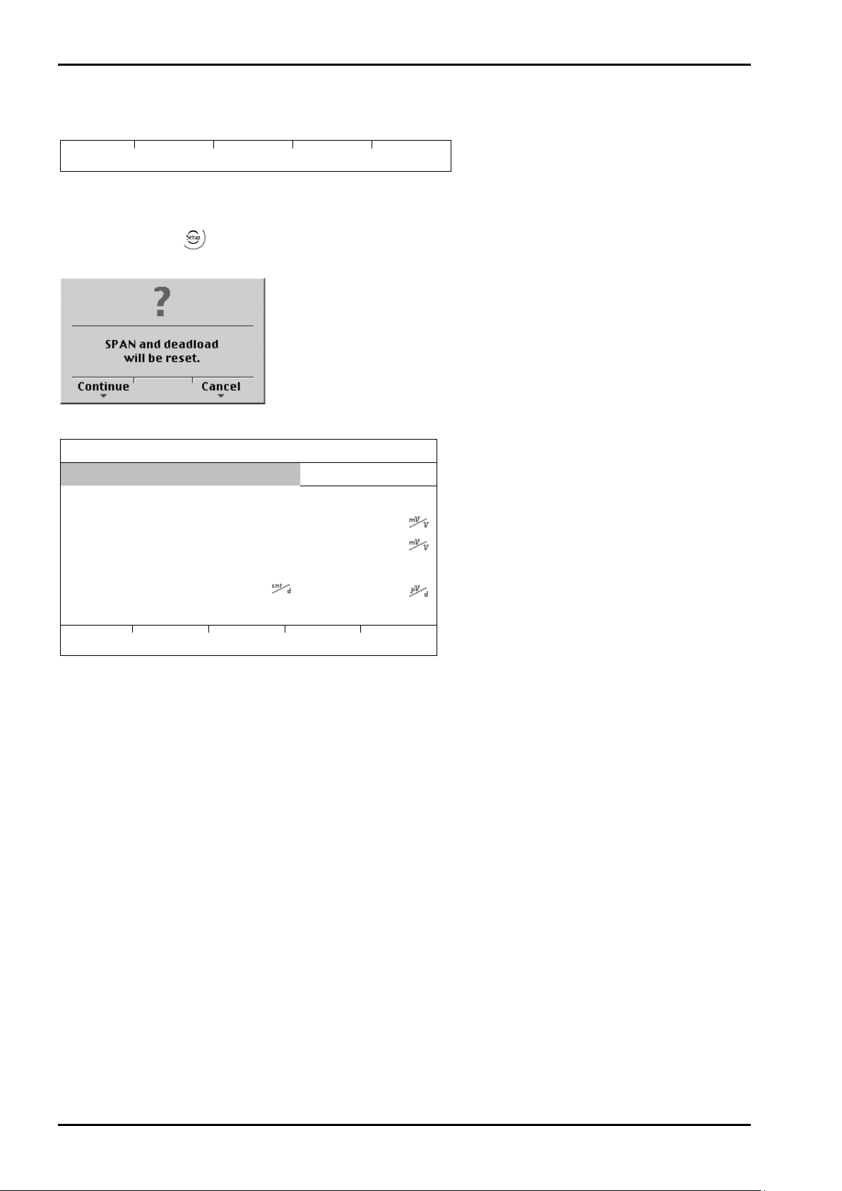
Commissioning
New
Modify
Param
You are prompted to confirm:
Weighingpoint/WP A/Calibration
Max
3000 d
3000 kg
Scale interval
3000 d
1 kg
Deadload at
0.000000
Max at 1.000000
Not calibrated
4.000000
CalcTest
PR 5220 Instrument Manual
4.4.2 Selecting the Calibration Mode
You can choose between [New] and [Modify] with the softkeys:
4.4.2.1 New Calibration
Open the menu via -[Weighingpoint]-[Calib]. When you press [New], the data is set to default first and
calibration is started.
Press [Continue] for the default settings, or [Cancel] to cancel the selection.
Default settings with [New]:
Sensitivity
833.33
EN-56 Sartorius
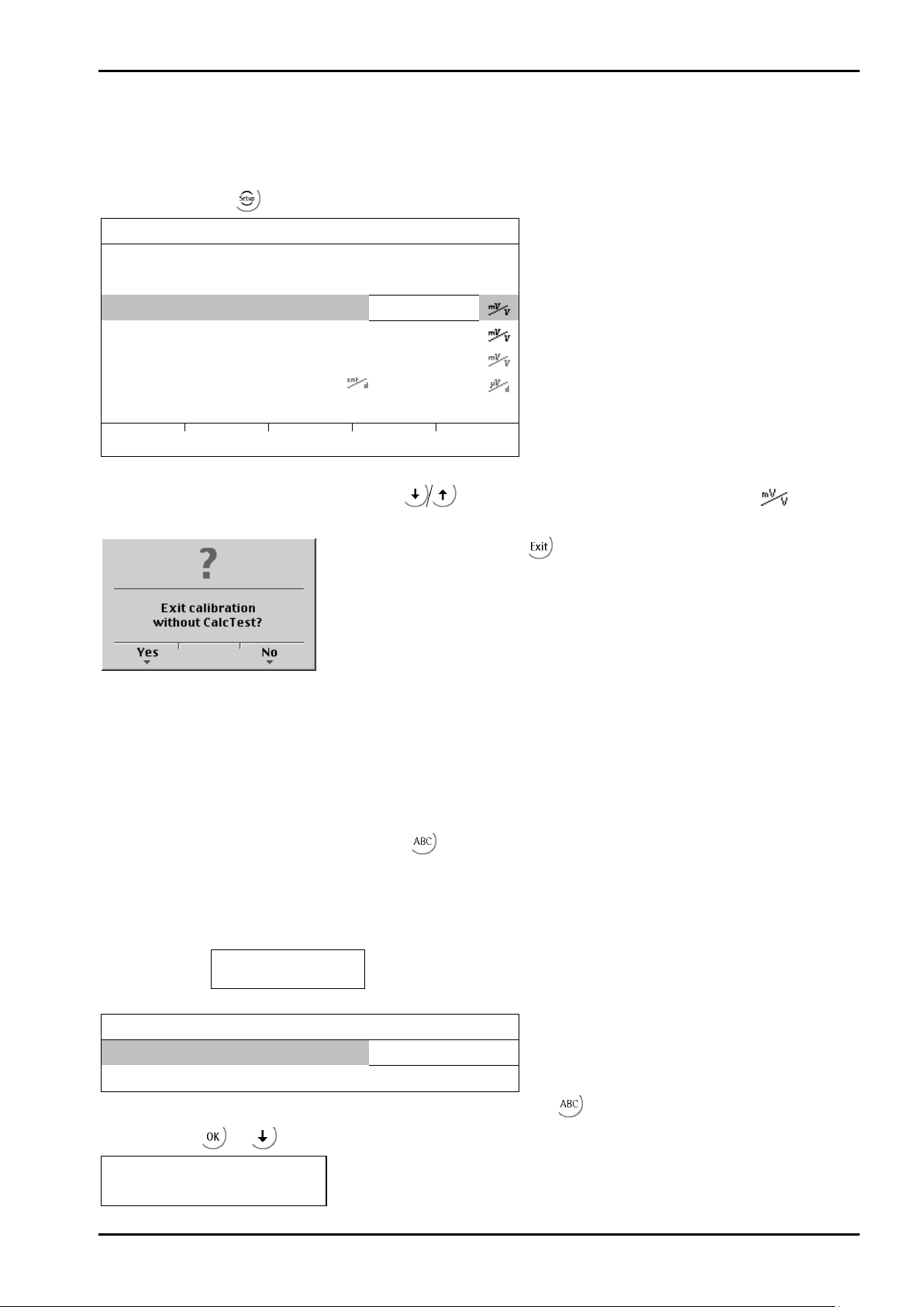
PR 5220 Instrument Manual Commissioning
Note:
[Modify] may be used only for minor changes (e.g. changing the dead load, adapting mV/V
Weighingpoint/WP A/Calibration
Max
3000 d
3000 kg
Scale interval
3000 d
1 kg
Deadload at
1.07 kg
0.000358
Max at
3000.00 kg
1.000000
Calibrated at
3000.00 kg
1.000000
Sensitivity
4.000000
by load
by mV/V
Test
Note:
If the liniarization is active (see Chapter 4.4.10):
Weighingpoint/WP A/Calibration
Max at
3000 d
3000 kg
4.4.2.2 Changing the Calibration
values for dead load and/or Max); otherwise, always use [New].
Open the menu via -[Weighingpoint]-[Calib] -[Modify].
833.33
For setting a new value for Dead load, press
to select [Deadload] and either enter a new value
with [by mV/V] or discharge the scale/hopper and press [by load].
When closing the menu with you are prompted whether the menu should
be closed without calculation of the test value:
Reply [Yes] to close the menu.
4.4.3 Determining the Maximum Capacity (Max)
The maximum capacity (Max) determines the maximum weight without dead load of the weight to be
measured and the displayed number of digits behind the decimal point. Normally, Max is less than the load cell
capacity (nominal capacity x number of load cells).
Permissible values are:
[Max] from 0.00010 to 999999, with
in kg, t, g or lb
Max must be an integer multiple of the scale interval. It may have up to 6 digits and is entered as a numeric
value with or without decimal point.
After selection of the line ‚Max at’ the following tip is displayed:
Can not be changed here
while linearization is active
The weight unit can be changed from kg into t, g or lb by pressing .
After pressing
or confirmation of the change is displayed with:
Setting Max
Sartorius EN-57

Commissioning
This message displays, if the maximum capacity is too high
Subsequent changing of the maximum capacity is possible; if you
This message displays, if the selected resolution is to low, e.g. 5 kg.
The selected resolution is so high that less than 0.8 internal counts per
This message displays, if the maximum capacity is not an integer
Possible Error messages
PR 5220 Instrument Manual
(the calculated input voltage for the specified maximum capacity
exceeds 36 mV).
decrease the capacity, a message is displayed if the new maximum
capacity is lower than the test load ([Calibrated at]).
scale interval (d) or 0.5 µV/e for legal-for-trade acc. to OIML/NSC are
available.
multiple of the scale interval.
After you press [OK], the input value for the maximum capacity is canceled.
EN-58 Sartorius

PR 5220 Instrument Manual Commissioning
Weighingpoint/WP A/Calibration
Max
3000 d
3000 kg
4.4.4 Determining the Scale Interval
Scale interval 3000 d
The weight unit is taken from [Max] and cannot be changed here.
The number of digits behind the decimal point must be determined already when entering [Max] as well.
After
or confirmation of the change is displayed with:
Set Scale interval
1kg
The maximum capacity is not an integer multiple of the scale interval.
The scale interval 1, 2, 5 10, 20 or 50
can be set by pressing .
Sartorius EN-59

Commissioning
Note:
If the liniarization is active (see Chapter 4.4.10):
Weighingpoint/WP A/Calibration
Max
3000 d
3000 kg
Scale interval
3000 d
1 kg
Deadload at
0.00 kg
0.000000
Max at
3000.00 kg
1.000000
Not calibrated
Sensitivity
833.33
4.000000
by load
by mV/V
CalcTest
Weighingpoint/WP A/Calibration
Max
3000 d
3000 kg
Scale interval
3000 d
1 kg
Deadload at
0.00 kg
0.000000
Max at
3000.00 kg
1.000000
Calibrated at
3000.00 kg
1.000000
Sensitivity
833.33
4.000000
by load
by mV/V
CalcTest
4.4.5 Determining the Dead Load
After selection of the line ‚Dead load at’ the following tip is displayed:
Can not be changed here
while linearization is active
To use the empty scale/hopper as dead load (normal case):
• discharge the scale/hopper
• press [by load]
PR 5220 Instrument Manual
After
If the mV/V value of the dead load was calculated, or if it is known from the previous calibration, the value can
be overwritten by pressing [by mV/V].
or confirmation of the change is displayed:
Set deadload
EN-60 Sartorius

PR 5220 Instrument Manual Commissioning
The dead load entered in mV/V plus maximum capacity in mV/V is higher
This message displays, if the scale is not stable.
This message displays, if the Measurement signal is negative when determining
This message displays, if dead load entered in mV/V is higher than 5 mV/V.
Possible error messages
than 3 mV/V (= 36 mV).
Remedial action
• Check the mechanical function of the scale.
• Adapt the filter setting; reduce the resolution, if necessary.
• Adapt the stability conditions.
the dead load with [by load].
Cause
Load cells connected with wrong polarity or defective.
Sartorius EN-61

Commissioning
The weight value for the calibration weight must be entered in
Weighingpoint /WP A/Calibration
Max
3000 d
3000 kg
Scale interval
3000 d
1 kg
Deadload at
165.11 kg
0.057920
Max at
3000.00 kg
1.052369
Calibrated at
2000 kg
0.701579
Sensitivity
876.97 4.209600
by load
by mV/V
by data
Linear.
CalcTest
This message displays, if the scale is not stable.
This message displays, if the weight on the scale is less than the dead load
PR 5220 Instrument Manual
4.4.6 Calibration with Weight (by Load)
Select [by load] for calibration using weight.
separate window.
After applying the weight, enter the weight value and confirm with . The weight unit for the calibration
weight (press
Afterward, the following message is displayed:
Setting SPAN by load
Weight value, weight unit and measuring signal in mV/V corresponding to this value are displayed in the
[Calibrated at] line.
to change) may differ from the unit in the instrument; conversion is automatic.
Remedial action
• Check the mechanical function of the scale.
• Adapt the filter setting; reduce the resolution, if necessary.
• Adapt the stability conditions.
after input of the weight value.
The next step is calculation of the test value with [CalcTest] (see Chapter 4.4.11), and calibration is completed
with
EN-62 Sartorius
(see Chapter 4.4.12).

PR 5220 Instrument Manual Commissioning
cells) load of number * load (nominalcapacity cell load
][mV/V Cn ysensitivit cell load capacity maximum
= [mV/V] SPAN
*
The calibration dialog provides an overview of all settings:
Weighingpoint/WP A/Calibration
Max
1000 d
1000 kg
Scale interval
1000 d
1 kg
Deadload at
500.00 kg
0.500000
Max at
1000.00 kg
1.000000
Calibrated at
1000.00 kg
1.000000
Sensitivity
2500.00
12.000000
4.4.7 Calibration with mV/V Value [by mV/V]
The scale can be calibrated without weights. During input of the load cell mV/V value, the acceleration of
gravity at the place of installation can be taken into account. The STAR load cell data is based on the
acceleration of gravity effective at Hamburg, Germany: 9.81379 m/s².
4.4.7.1 SPAN
Span indicates the equivalent input voltage in mV/V related to the maximum capacity (Max) of the scale. It is
calculated as follows:
Load cell sensitivity Cn = rated output Cn (see technical data of the load cell)
4.4.7.2 Dead Load
The input voltage in mV/V equivalent to the dead load can be calculated by using the dead load rather than
the maximum capacity in the formula specified above.
Normally, calculation of the dead load (scale without load/empty hopper) is not necessary. Subsequent dead
load correction (as described in Chapter 4.4.9) can be used for later re-determination of the dead load, when
the scale/hopper is empty.
Example
- Load cell(s) with rated output of 2 mV/V
- at nominal load of 2,000 kg,
- dead load 500 kg
- load cell supply voltage 12 V DC
After selecting [mV/V], the values for the Max and for the dead load (if necessary) can be entered.
The next step is calculation of the test value with [CalcTest] (see Chapter 4.4.11).
The calibration is completed by pressing
Sartorius EN-63
(see Chapter 4.4.12).

Commissioning
Weighingpoint/WP A/Calibration
Max
3000 d
3000 kg
Scale interval
3000 d
1 kg
Deadload at
3.00 kg
0.001000
Max at
3000.00 kg
0.000000
Not calibrated
Sensitivity
833.33 4.000000
by load
by mV/V
by data
Linear.
CalcTest
Weighingpoint/WP A/Calibration/Load cell configuration
Nominal load
3000 kg
Gravity
9.81379 m/s²
Hysteresis error
not specified
Certified data
all LC same
LC sensitivity
1.000000
Enter
Calc
Weighingpoint/WP A/Calibration/Load cell configuration
600.000
Enter
Calc
PR 5220 Instrument Manual
4.4.8 Calibration with Load Cell Data (“Smart Calibration“)
If the scale to be calibrated is not legal for trade, it can be calibrated without weights. The easiest method is
the one using load cell data without calculation [by data].
Start by pressing [by data].
Number of load cells
LC resistance
[Number of load cells]
Number of load cells connected in parallel (1, 2...<4>...9, 10)
[Nominal load]
Max. capacity E
of a load cell (not the overall nominal weight of the scale).
max
4
¥
[Gravity]
Acceleration of gravity at the place of installation; default is the value for Hamburg, Germany, 9.81379 m/s².
[Hysteresis error]
When switching from [Not specified] to [Specified], values for [Correction A/B] must be filled in. The data is
given on the load cell certificate.
[Certified data], [LC sensitivity], [LC resistance]
With [all LC same], only 1 value for the sensitivity [LC sensitivity] and the output resistance [LC resistance]
must be filled in. With [each LC specific], individual values for each load cell are requested.
[Calc]
The mV/V value is calculated and after confirmation with [OK], the calculated mV/V value is stored in the
calibration data.
EN-64 Sartorius
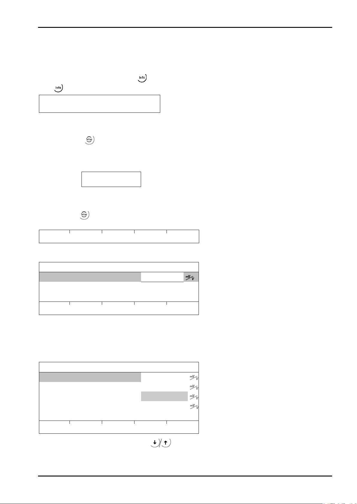
PR 5220 Instrument Manual Commissioning
Note:
If the liniarization is active (see Chapter 4.4.10):
by load
by mV/V
by data
Linear.
CalcTest
Weighingpoint/WP A/Calibration/Linearization
Max at
3000.00 kg
1.000000
Add
by mV/V
by load
Weighingpoint/WP A/Calibration/Linearization
1. Lin. point
750 kg
0.250010
2. Lin. point
1500 kg
0.500020
3. Lin. point
2250 kg
0.750040
Max at
3000.00 kg
1.000000
Add
Change
Delete
by mV/V
by load
4.4.9 Subsequent Dead Load Correction
If the hopper/platform weight changes by an amount that is higher than the zero-setting range; e.g., due to
dead load reduction, dead load increase or mechanical changes, the functions for automatic zero tracking and
manual zero setting no longer work. To view the range which is already utilized by zero tracking or zero
setting, select [Calibration] and press
Press
again to return to the previous state:
Current zero setting: 0.123 kg
If the entire zero-setting range is already utilized, you can still correct the dead load (CAL switch must be
open) without affecting other calibration data/parameters.
; this also activates 10-fold increased resolution of the weight value.
To do this, select
-[Weighingpoint]-[Calib]-[Modify] and determine the dead load with [Dead load at]-[by
load] (see Chapter 4.4.5).
After selection of the line ‚Dead load at’ the following tip is displayed:
Can not be changed here
while linearization is active
4.4.10 Linearization
After selecting -[Weighingpoint]-[Calib]-[New]/[Modify] and after completing calibration, select the
linearization menu with softkey [Linear.]:
When you press [Linear], the menu shown below appears:
To add a new linearization point, press [Add], fill in the weight value, apply the weight and press [by load].
Then fill in the corresponding value in mV/V for the weight. After pressing [mV/V], the value can be entered
directly.
Up to 3 linearization points can be determined.
A linearization point can be added with [Add], removed with [Delete] and changed with [Change].
A linearization point can be selected with
Sartorius EN-65
changed with [Change] and deleted with [Delete].
,

Commissioning
Weighingpoint/WP A/Calibration
CalcTest
- the maximum capacity with [Absolute], or
You are prompted to confirm whether calibration should be closed without
If not all data was determined when calibrating with [New] (e.g. dead load
Press [Save] to save changes in calibration data. If you press [Undo], changes
The confirmation is displayed as follows:
PR 5220 Instrument Manual
4.4.11 Test Value Determination/Display
Press [Test] to activate test value calculation. The maximum capacity (Max) is displayed with the
designation
The value determined during calibration after starting the test [CalcTest] is shown.
Depending on the settings under -[Weighingpoint]-[Calib]-[Param]-[Test mode], either
without a weight unit.
- the deviation from the test value with [Relative]
is shown when you press
to view the test data.
4.4.12 Finishing/Saving the Calibration
Finish the calibration with .
determining the test value.
not set/entered), this message is shown:
Press [Yes] to confirm and then press again; another prompt is displayed:
are not saved and the display returns to the selection menu for the
weighing points.
Saving calibration
After quitting the menu, the following message is displayed:
Exit calibration
After finishing the calibration, set the CAL switch to the closed position; see also Chapter 4.1.1.
EN-66 Sartorius

PR 5220 Instrument Manual Commissioning
Weighingpoint/WP A/Calibration
Digital filter
bessel
External supply
8 - 12 VDC
Fcut
3.00 Hz
This line is shown only if the filter is on.
Test mode
absolute
W & M
none
Standstill time
0.50 s
Standstill range
1.00 d
4.4.13 Parameter Input
Open the menu via -[Weighingpoint]-[Calib]-[Param].
Measuretime
[Measuretime]
Select the measuring time; possible values: 5, 10, 20, 40, 80, 160, 320, 640, 960, 1280, 1600 ms.
In 'legal-for-trade' mode select ≤1 s.
[Digital filter]
The digital filter can be switched on only with the measuring time set to ≤160 ms.
Select the filter characteristic [off], [bessel], [aperiod.], [butterw.], [tscheby.].
[Fcut]
Enter the cut-off frequency for the filter (0.1…80 Hz); the setting is dependent on the measuring time.
160 ms
[External supply]
With external load cell supply (e.g. 7.5 V DC via 1626/60 with MX8 = closed), [below 8 VDC] can be selected to
adapt the sense voltage monitoring to the lower supply voltage.
[Test mode]
With [Absolute], the test value is calculated when the test is called. With [relative], the deviation from the
initially stored test value is displayed; see Chapter 4.4.11.
[W & M]
Setting for 'legal-for-trade' mode; select [none], [OIML], [NTEP] (for USA) or [NSC] (for Australia),
see Chapter 4.4.13.1.
[Standstill time]
Settings [Standstill range] and [Standstill time] are required for determining the mechanical stability of the
scale. Input in seconds; permissible range 0.01 bis 2 sec. (max. measuring time x 32). If 0 is set, stability is not
checked. The stability time must not be less than the measuring time and not greater than 32 times the
measuring time.
[Standstill range]
The scale is stable as long as any changes in the weight value are within this range; permissible range:
0.01d to 10.00d. In 'legal-for-trade' mode select ≤1 d.
Sartorius EN-67

Commissioning
Weighingpoint/WP A/Calibration
Tare timeout
2.5
s Zeroset range
50.00 d
Zerotrack range
0.25 d
Zerotrack step
0.25 d
Zerotrack time
0.0 s
Overload
9 d
Weighingpoint/WP A/Calibration
Minimum weight 50
d Range mode Single range
[Tare timeout]
Enter a timeout value between 0.1 and 25 s for a taring/zero set command that cannot be executed (e.g., if
scale mechanically unstable, filter settings faulty, resolution too high, stability condition too narrow).
[Zeroset range]
Determine a ±range around the zero point determined by the dead load during calibration; within this range:
- the displayed gross weight can be set to zero by pressing the zero-setting key (or by a corresponding
external command), and
- automatic zero tracking is active.
Available range: 0.00 d to 10000.00d
In 'legal-for-trade' mode a value ≤ 2 % of Max. must be entered. Example: 60 d for 3000e, class III.
PR 5220 Instrument Manual
[Zerotrack range]
Range within which automatic zero tracking compensates deviations; 0.25 to 10000.00d.
In 'legal-for-trade' mode a value of 0.25 d has to be entered.
[Zerotrack step]
Step for automatic tracking; 0.25 to 10d. In 'legal-for-trade' mode a value of 0.25 d has to be entered.
[Zerotrack time]
Enter a time interval for automatic zero tracking within 0.0 (tracking switched off) and 25 s.
In 'legal-for-trade' mode a value of 0.25 d has to be entered.
[Overload]
Weighing range above the maximum capacity (Max), without error message. Available range: 0 to 9999900 d.
In 'legal-for-trade' mode max. 9 d=e has to be entered.
[Minimum weight]
Minimum weight at which a print command can still be executed. Range is 0 to 9999900 d.
In 'legal-for-trade' mode min. 20 d has to be entered.
[Range mode]
For scale range selection, see Chapter 4.4.13.2.
EN-68 Sartorius

PR 5220 Instrument Manual Commissioning
Gross weight display
Weighingpoint/WP A/Calibration
Range limit 1
1000 kg
Range limit 2
2000 kg
4.4.13.1 Legal-for-Trade Operation
Under -[Weighingpoint]-[Calib]-[Param]-[W&M] you can choose between:
[none] and a legal-for-trade mode [OIML], [NTEP] or [NSC].
Min. meas. signal
If legal-for-trade operation is selected, the parameters (zero tracking etc.) must be set accordingly; they are
not checked. The relevant CAL switch (see Chapter 4.1.1) must be sealed in the closed position.
[none] [OIML] [NTEP] [NSC]
0.125 mV/V
at 30000 d
0.25 mV/V
at 60000 d
0.125 mV/V
at 3000 e
0.25 mV/V
at 6000 e
0.42 mV/V
at 10000 e
0.125 mV/V
at 3000 e
0.25 mV/V
at 6000 e
0.42 mV/V
at 10000 e
0.125 mV/V
at 3000 e
0.25 mV/V
at 6000 e
0.42 mV/V
at 10000 e
4.4.13.2 Multiple Range Scale/Multi-Interval Scale
Range selection is controlled by three parameters under -[Weighingpoint]-[Calib]-[Param].
Range mode
Multiple range
Select [Multiple range] or [Multi-interval]
Switch point from range 1 to 2
Switch point from range 2 to 3
Multiple Range Scale (Class III or one range scale Class I and II with variable interval)
With [Range mode] = [Multiple range], the scale has up to 3 ranges with different resolutions.
The corresponding ranges are indicated above the mass unit as follows:
, or
The switch points [Range limit 1] and [Range limit 2] are the range limits. As soon as the gross weight exceeds
range 1, the next higher range with the next higher interval becomes valid (1->2->5->10->20->50->100>200). When reducing the weight, the interval of the previous range is kept. When the gross weight is ≤0,25 d
of range 1 and the scale is stable and not tared, the scale returns to range 1 with the corresponding interval.
Multi-Interval Scale (Class III or one range scale Class I and II with variable interval)
With [Range mode] = [Multi-interval], the scale has up to three ranges with different resolution. Each range
has the corresponding interval. Unlike [Multiple range], switching the interval is also triggered by weight
reduction; i.e., when the weight drops below the range limits.
During calibration, the multiple range/multi-interval function is always switched off.
Display VNC
The weight display header includes the current range (R1, R2, and R3), Max, Min and d (or e with legal-fortrade instruments) (Example: multiple range scale in range 2):
Sartorius EN-69

Commissioning
Setup/Serial ports
Remote display
-none-
SMA
-none-
Param
Setup/Serial ports/Slot1 RS485
Assigned to
xBPI-Port
Bits
8
Parity
odd
Stopbits
1
1, 2
PR 5220 Instrument Manual
4.5 Calibrating an xBPI Scale
Legal-for-trade application of PR 5220 with an xBPI scale is not possible.
4.5.1 xBPI Set-up for Serial Port
Determination and setting of the interface to which the scale/platform is connected must be done in menu
-[Serial ports parameter]-[xBPI-Port].
xBPI-Port
The menu appears.
Baudrate
Builtin RS485
9600 bd
Select the interface for the xBPI scale with
Press [Param].
Select with and
set the following parameters with
.
.
EN-70 Sartorius
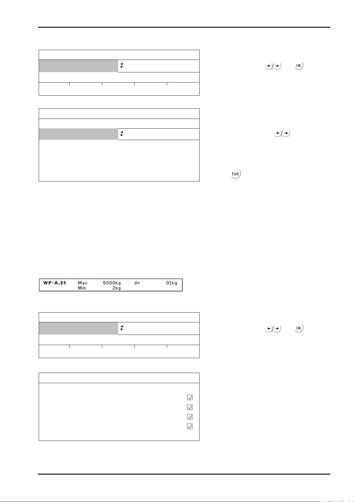
PR 5220 Instrument Manual Commissioning
Weighingpoint
Setup
Config
Param
Weighingpoint/WP A
Type
xBPI-Scale
Tare timeout
1.0 s
Serial number
0
SBN Address
0
Weighingpoint
Setup
Config
Param
Weighingpoint/xBPI-Scale Setup
Reading parameters
model
metrologie
Ticks indicate the progress.
device info
settings
4.5.2 xBPI Scale Function
Weighingpoint A
xBPI-Scale
Select [xBPI-Scale] with and .
Select [Config].
The menu appears.
W&M
none
Select the W
&M mode with
.
Leave with .
[Tare timeout]
Waiting time for the execution of a zero set or taring command. If the xBPI-scale has not executed the
command in the specified time, the action will be aborted.
[Serial number]
Serial number of the connected xBPI scale/weighing module. The number is required for checking with legal
for trade application. With serial number 0, checking is omitted.
[SBN Address]
With an address unequal to 0, bus operation active, possible addresses: 1 - 31, i.e. max. 31 xBPI scales can be
operated at an RS 485 bus line. The SBN Address is shown in the display.
Example: Address 31 at WP-A.
4.5.3 xBPI Platform Configuration
Weighingpoint A
Read the parameters from the xBPI scale with [Setup].
xBPI-Scale
Select [xBPI-Scale] with and .
Select [Setup].
An error message displays, unless communication with the xBPI scale is possible!
Sartorius EN-71

Commissioning
Weighingpoint/xBPI-Scale Setup
Calibration
Configuration
Show device info
Weighingpoint/xBPI-Scale Setup
Specification group 1
Specification group 2
Specification group 4
Specification group 5
?
Yes No
Weighingpoint/xBPI-Scale Setup
Saving changes parameters
download values
Ticks indicate the progress.
write nonvolatile
reconfig system
PR 5220 Instrument Manual
Select group of specification
Selection of specification group (see operating instructions of the scale):
Specification group 3
Specification group 6
Save changes?
Open with
Select with
Leave with
.
and .
.
Save the data with [Yes].
Press [NO] for exit from the menu without data change.
EN-72 Sartorius
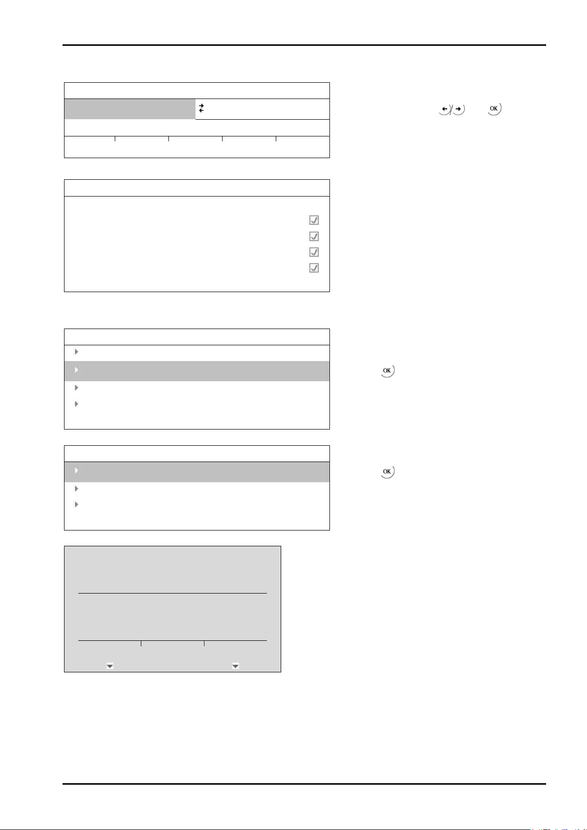
PR 5220 Instrument Manual Commissioning
Weighingpoint
Setup
Config
Param
Weighingpoint/xBPI-Scale Setup
Reading parameters
model
metrologie
Ticks indicate the progress.
device info
settings
Weighingpoint/xBPI-Scale Setup
Calibration
Select group of specification
Show device info
Weighingpoint/xBPI-Scale Setup
Application settings
For further procedure, see Chapter 4.5.5.
Interface settings
?
Yes No
4.5.4 xBPI Scale Parameter
Weighingpoint A
Read the parameters from the xBPI scale with [Setup].
An error message displays, unless communication with the xBPI scale is possible!
Configuration
xBPI-Scale
Select [xBPI-Scale] with and .
Select [Setup].
Open with .
Weighing parameters
Save changes?
Save the data with [Yes].
Press [NO] for exit from the menu without data change.
Open with .
Sartorius EN-73

Commissioning
Weighingpoint/xBPI-Scale Setup
Stability range
8 digit
Stability symb. delay
no delay
Tare parameter
at any time
Auto zero function
Auto Zero off
- Ambient conditions
- Very stable cond.
- Stable conditions
- Unstable cond.
- Very unstable cond
- Application/Filter
- standard mode
- manual filling
- automatic dosing
- checkweighing
- Stability range
- 0,25 digit
- 0,5 digit
- 1 digit
- 2 digit
- 4 digit
- 8 digit
- Stability symb.delay
- no delay
- short delay
- long delay
- extrem long delay
- Tare parameter
- at any time
- not until stable
- Auto zero function
- Auto Zero on
- Auto Zero off
- Adjustment function
- ext.adj.w.fact.wt.
- ext.adj.w.user.wt.
- ext.adj.w.pres.wt.
- internal adjust
- ext.lin.w.fact.wt.
- ext.lin.w.pres.wt.
- Confirm preload
- Delete preload
- adjust disabled
- Confirming adjust.
- automatically
- manual
- Zero range
- 1% of max load
- 2% of max load
- 5% of max load
- 10% of max load
- Power-On zero range
- factory settings
- 2% of max load
- 5% of max load
- 10% of max load
- 20% of max load
- Power-On tare/zero
- activ
- inactiv
- only for zeroing
- Measure rate
- normal output
- fast output
- Calibration check
- Off
- Calibration prompt
- External adjustment
- Accessible
- Blocked
- Maximum capacity
- reduced by preload
- constant
PR 5220 Instrument Manual
4.5.5 xBPI Parameter Tables
The parameters which must be entered in -[Weighingpoint]-[xBPI-xBPI-Scale]-[Setup]-[Configuration][Weighing parameters]/[Application settings]/[Interface settings] are listed in the following tables.
Ambient conditions
Very stable cond.
Application/Filter standard mode
Select the parameter with
Make the setting with
Leave with .
and
.
[Weighingpoint A-xBPI-scale]-[Setup]-[Configuration]-[Weighing parameters]
EN-74 Sartorius

PR 5220 Instrument Manual Commissioning
- Application Tare
- Accessible
- Blocked
- Number of units
- 1 weight unit
- 2 weight units
- 3 weight units
- Weight unit 1
- gramm g
- kilogram kg
- Carat ct
- Pound lb
- Unze oz
- Troy unze ozt
- Tael Hongkong tlh
- Tael Singapur tls
- Tael Taiwan tlt
- grain GN
- pennyweight dwt
- milligramm mg
- Parts/pound /lb
- Tael china tlc
- Momme mom
- Karat k
- Tola tol
- Baht bat
- Mesghal m
- Tonne t
- Display accuracy 1
- all digits
- reduced when moved
- one level lower
- two levels lower
- three levels lower
- 1%
- 0.5%
- 0.2%
- 0.1%
- 0.05%
- 0.02%
- 0.01%
- Multiinterval
- increased by 10
- Weight unit 2
- gramm g
- kilogram kg
- Carat ct
- Pound lb
- Unze oz
- Troy unze ozt
- Tael Hongkong tlh
- Tael Singapur tls
- Tael Taiwan tlt
- grain GN
- pennyweight dwt
- milligramm mg
- Parts/pound /lb
- Tael china tlc
- Momme mom
- Karat k
- Tola tol
- Baht bat
- Mesghal m
- Tonne t
- Display accuracy 2
- all digits
- reduced when moved
- one level lower
- two levels lower
- three levels lower
- 1%
- 0.5%
- 0.2%
- 0.1%
- 0.05%
- 0.02%
- 0.01%
- Multiinterval
- increased by 10
- Weight unit 3
- gramm g
- kilogram kg
- Carat ct
- Pound lb
- Unze oz
- Troy unze ozt
- Tael Hongkong tlh
- Tael Singapur tls
- Tael Taiwan tlt
- grain GN
- pennyweight dwt
- milligramm mg
- Parts/pound /lb
- Tael china tlc
- Momme mom
- Karat k
- Tola tol
- Baht bat
- Mesghal m
- Tonne t
- Display accuracy 3
- all digits
- reduced when moved
- one level lower
- two levels lower
- three levels lower
- 1%
- 0.5%
- 0.2%
- 0.1%
- 0.05%
- 0.02%
- 0.01%
- Multiinterval
- increased by 10
[Weighingpoint A-xBPI-scale]-[Setup]-[Configuration]-[Application settings]
Sartorius EN-75

Commissioning
- Communication type
- SBI protocol
- xBPI protocol
- Baudrate for SBI
- 150 baud
- 300 baud
- 600 baud
- 1200 baud
- 2400 baud
- 4800 baud
- 9600 baud
- 19200 baud
- Parity for SBI
- Mark
- Space
- Odd
- Even
- Stop bits
- 1 stop bit
- 2 stop bits
- Handshake
- software handshake
- CTS with 2 chr.pau
- CTS with 1 chr.pau
- Data output print
- on requ always
- on requ when stab
- on requ with store
- auto
- auto when stable
- Auto print
- start/stop by ESCP
- not stoppable
- Output format
- without ID 16 byte
- with ID 22 byte
- Data output interval
- with each display
- after 2 updates
- after 5 updates
- after 10 updates
- after 20 updates
- after 50 updates
- after 100 updates
- Parameter change
- can be changed
- cannot be changed
PR 5220 Instrument Manual
[Weighingpoint A-xBPI-scale]-[Setup]-[Configuration]-[Interface settings]
EN-76 Sartorius

PR 5220 Instrument Manual Commissioning
Note:
Both terms 'dead load' and 'preload' are used by Sartorius.
Weighingpoint
Setup
Config
Param
Weighingpoint/xBPI-Scale Setup
Reading parameters
model
metrologie
Ticks indicate the progress.
device info
settings
Weighingpoint/xBPI-Scale Setup
Configuration
Select group of specification
Show device info
Weighingpoint/xBPI-Scale Setup
Dead load
Set
Set dead load.
Delete
Delete dead load.
Span
Adjust with user weight
Adjust with auto weight
4.5.6 xBPI Setting Dead Load
Weighingpoint A
xBPI-Scale
Select [xBPI-Scale] with and .
Select [Setup].
Read the parameters from the xBPI scale with [Setup].
An error message displays, unless communication with the xBPI scale is possible!
Calibration
Open with .
Leave with .
For setting the dead load, remove the weight from the scale and select [Set]. After sending the command, 0 is
indicated on the gross weight display.
Alternatively, the stored dead load can be deleted:
Remove the weight from the scale and select [Delete]. The stored dead load is deleted. The instantaneous dead
load is shown on the weight display.
Sartorius EN-77

Commissioning
Weighingpoint/xBPI-Scale Setup
Configuration
Select group of specification
Show device info
Weighingpoint/xBPI-Scale Setup
Dead load
Set
Delete
Span
Adjust with auto weight
Enter user weight
The previously stored user weight is displayed.
2000 g
The weight can be changed.
Weighingpoint/xBPI-Scale Setup
Calibration status
Load to small
Calibration progress without weight.
Cal-Target
-2000 g
--
0.01 g
Weighingpoint/xBPI-Scale Setup
Calibration status
Difference display
Cal-Delta
-0.3 g
--
1999.75 g
The weight is displayed in high-resolution (10x).
Accept
ResError
Abort
PR 5220 Instrument Manual
4.5.7 xBPI Calibration with the User Weight
Prerequisites:
- The xBPI protocol has been selected (see Chapter 4.5.1).
- The weighing point ‚xBPI-scale’ has been selected (see Chapter 4.5.4).
- The platform configuration has been executed (see Chapter 4.5.3).
- The setting in the following menu has been done: [Weighingpoint A-xBPI-Scale]-[Setup]:
[Configuration]-[Confirming adjust.]: [manual] (see Chapter 4.5.5).
- The communication between instrument and platform is active.
Calibration
Adjust with user weight
Following window appears:
Open with .
Select with and enter with .
The following window is displayed after applying the weight:
EN-78 Sartorius
Select [Accept].

PR 5220 Instrument Manual Commissioning
Weighingpoint/xBPI-Scale Setup
Calibration status
complete
Net=Grs
2000 g
--
2000.01 g
The weight is displayed in high-resolution (10x).
Accept
ResError
Abort
Weighingpoint/xBPI-Scale Setup
Configuration
Select group of specification
Show device info
Weighingpoint/xBPI-Scale Setup
Dead load
Set
Delete
Span
Adjust with user weight
Weighingpoint/xBPI-Scale Setup
Calibration status
Load to small
Calibration progress without weight.
Cal-Target
-10000.0 g
The weight is displayed in high-resolution (10x).
--
-0.02 g
The data are saved and the instrument generates a corresponding message:
Leave with .
4.5.8 xBPI Calibration with Automatic Weight Detection
Prerequisites:
- The xBPI protocol has been selected (see Chapter 4.5.1).
- The weighing point ‚xBPI-scale’ has been selected (see Chapter 4.5.4).
- The platform configuration has been executed (see Chapter 4.5.3).
- The setting in the following menu has been done: [Weighingpoint A-xBPI-Scale]-[Setup]:
[Configuration]-[Confirming adjust.]: [manual] (see Chapter 4.5.5).
- The communication between instrument and platform is active.
Calibration
Adjust with auto weight
Following window appears:
Open with .
Select with and enter with .
Sartorius EN-79
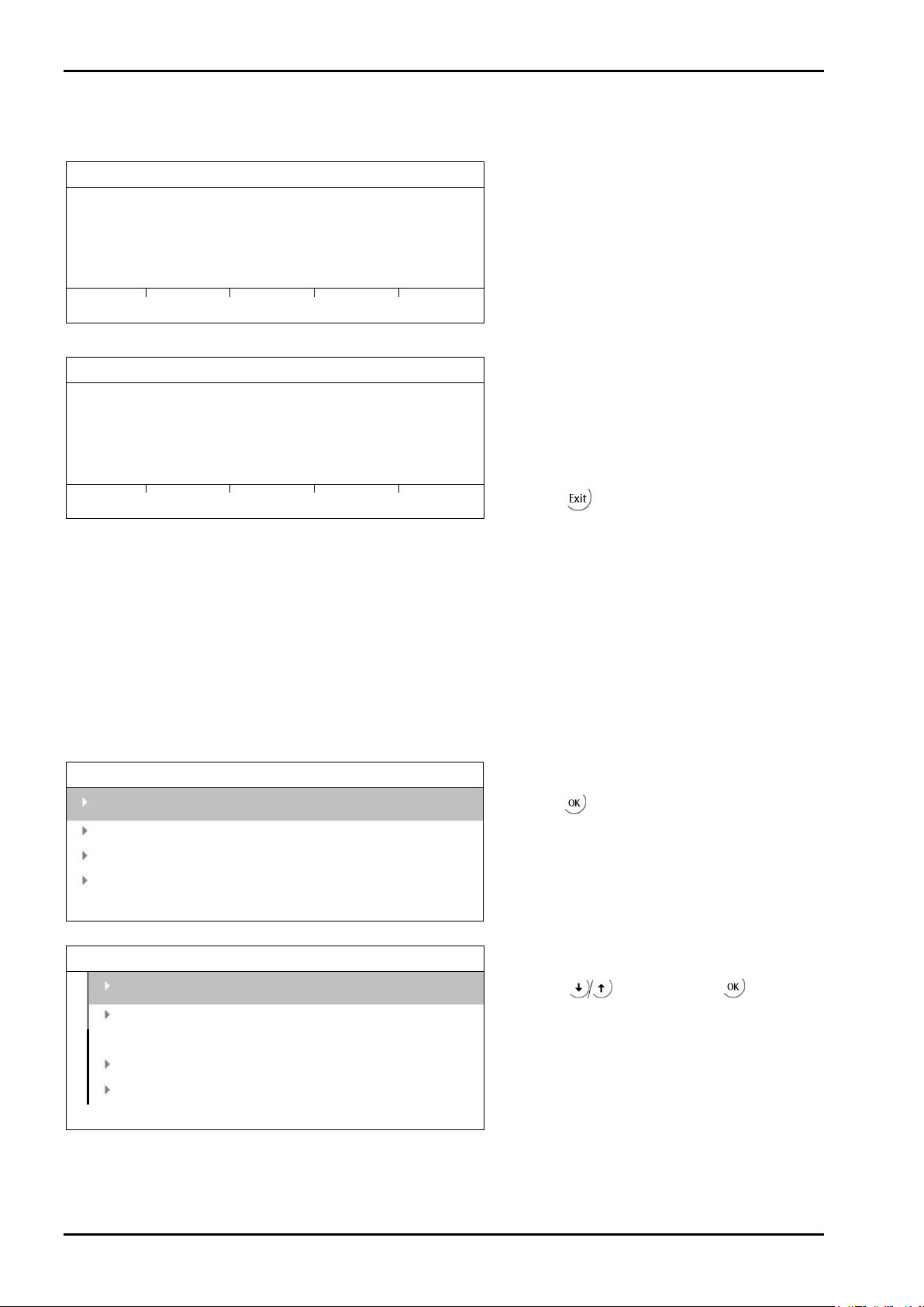
Commissioning
Weighingpoint/xBPI-Scale Setup
Calibration status
Difference display
Cal-Delta
0.1 g
--
5000.06 g
The weight is displayed in high-resolution (10x).
Accept
ResError
Abort
Weighingpoint/xBPI-Scale Setup
Calibration status
complete
Net=Grs
5000.0 g
--
5000.01 g
The weight is displayed in high-resolution (10x).
Accept
ResError
Abort
Weighingpoint/xBPI-Scale Setup
Configuration
Select group of specification
Show device info
Weighingpoint/xBPI-Scale Setup
Adjust with intern weight
Linearity
Default
User
In this example, a weight of 5000 g is put onto the scale.
The following window is displayed after applying the weight:
PR 5220 Instrument Manual
The data are saved and the instrument generates a corresponding message:
Select [Accept].
Leave with .
4.5.9 xBPI Calibration with Default Weight
Prerequisites:
- The xBPI protocol has been selected (see Chapter 4.5.1).
- The weighing point ‚xBPI-scale’ has been selected (see Chapter 4.5.4).
- The platform configuration has been executed (see Chapter 4.5.3).
- The setting in the following menu has been done: [Weighingpoint A-xBPI-Scale]-[Setup]:
[Configuration]-[Confirming adjust.]: [manual] (see Chapter 4.5.5).
- The communication between instrument and platform is active.
Calibration
Adjust with default weight
EN-80 Sartorius
Open with .
Select with and enter with .

PR 5220 Instrument Manual Commissioning
Weighingpoint/xBPI-Scale Setup
Calibration status
Load to small
Cal-Target
-5000.0 g
--
0.00 g
Weighingpoint/xBPI-Scale Setup
Calibration status
Difference display
Calibration progress without weight.
Cal-Delta
-0.0 g
--
4999.98 g
The weight is displayed in high-resolution (10x).
Accept
ResError
Abort
Weighingpoint/xBPI-Scale Setup
Calibration status
complete
Net=Grs
5000.0 g
--
5000.00 g
The weight is displayed in high-resolution (10x).
Accept
ResError
Abort
Following window appears:
The following window is displayed after applying the weight:
Select [Accept].
The data are saved and the instrument generates a corresponding message:
Leave with .
Sartorius EN-81
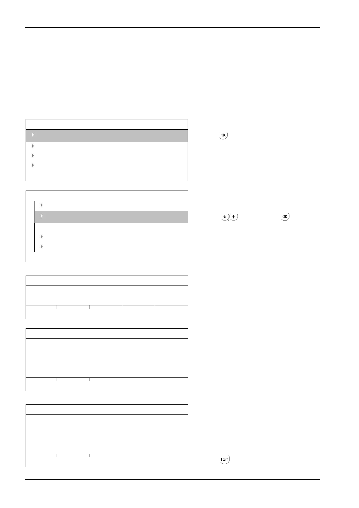
Commissioning
Weighingpoint/xBPI-Scale Setup
Configuration
Select group of specification
Show device info
Weighingpoint/xBPI-Scale Setup
Adjust with default weight
Linearity
Default
User
Weighingpoint/xBPI-Scale Setup
Calibration status
Motor in motion
The calibration progress is displayed.
Accept
ResError
Abort
Weighingpoint/xBPI-Scale Setup
Calibration status
Difference display
Cal-Delta
0.0 g
--
1212.73 g
Accept
ResError
Abort
Weighingpoint/xBPI-Scale Setup
Calibration status
complete
Net=Grs
-0.0 g
--
-0.06 g
Accept
ResError
Abort
PR 5220 Instrument Manual
4.5.10 xBPI Calibration with Built-in Weight
Prerequisites:
- The xBPI protocol has been selected (see Chapter 4.5.1).
- The weighing point ‚xBPI-scale’ has been selected (see Chapter 4.5.4).
- The platform configuration has been executed (see Chapter 4.5.3).
- The setting in the following menu has been done: [Weighingpoint A-xBPI-Scale]-[Setup]:
[Configuration]-[Confirming adjust.]: [manual] (see Chapter 4.5.5).
- The communication between instrument and platform is active.
Calibration
Adjust with intern weight
The procedure is shown e.g. with the following message:
Open with .
Select with and enter with .
The data are saved and the instrument generates a corresponding message:
EN-82 Sartorius
Select [Accept].
Leave with .

PR 5220 Instrument Manual Commissioning
Info/HW-Slots
Builtin
RS485
Builtin
analog out
Builtin
digital I/O
Slot 4
PR5220/01
Profibus-DP
Setup/Serial ports
Remote display
-none-
SMA
-none-
Param
Setup/Serial ports/Slot2 RS485
Assigned to
xBPI-Port
Protocol
xBPI
Bits
8
Parity
odd
4.6 Calibrating Digital Load Cells Type ‘Pendeo®’
4.6.1 General Information
The digital load cells have been calibrated at the factory based on the acceleration of gravity Hamburg,
Germany: 9.81379 m/s². The calibration data in the load cells are invariable. The calibration data for the
gravity acceleration at the place of installation can be adapted only in the instrument and protected against
overwriting (see Chapter 4.1.1). With applications for use in legal metrology, the legal requirements and the
conditions given on the test/approval certificate must be taken into account when selecting the settings.
For connecting digital load cells (xBPI load cells) a Firmware from 2.10 onwards is required.
4.6.2 Viewing the Interfaces
The existing interfaces can be viewed under -[Show HW-slots]:
Built-in interface
Built-in interface
4.6.3 Selecting and Setting up the Interface
Select -[Serial ports parameter]-[xBPI-Port] to choose a serial interface.
xBPI-Port
The menu appears.
Baudrate
Builtin RS485
19200 bd
Press to select RS-485.
Press [Param].
Press
to select the value ‚19200 bd‘.
Stopbits 1
Press
to select the value ‚1‘.
Sartorius EN-83
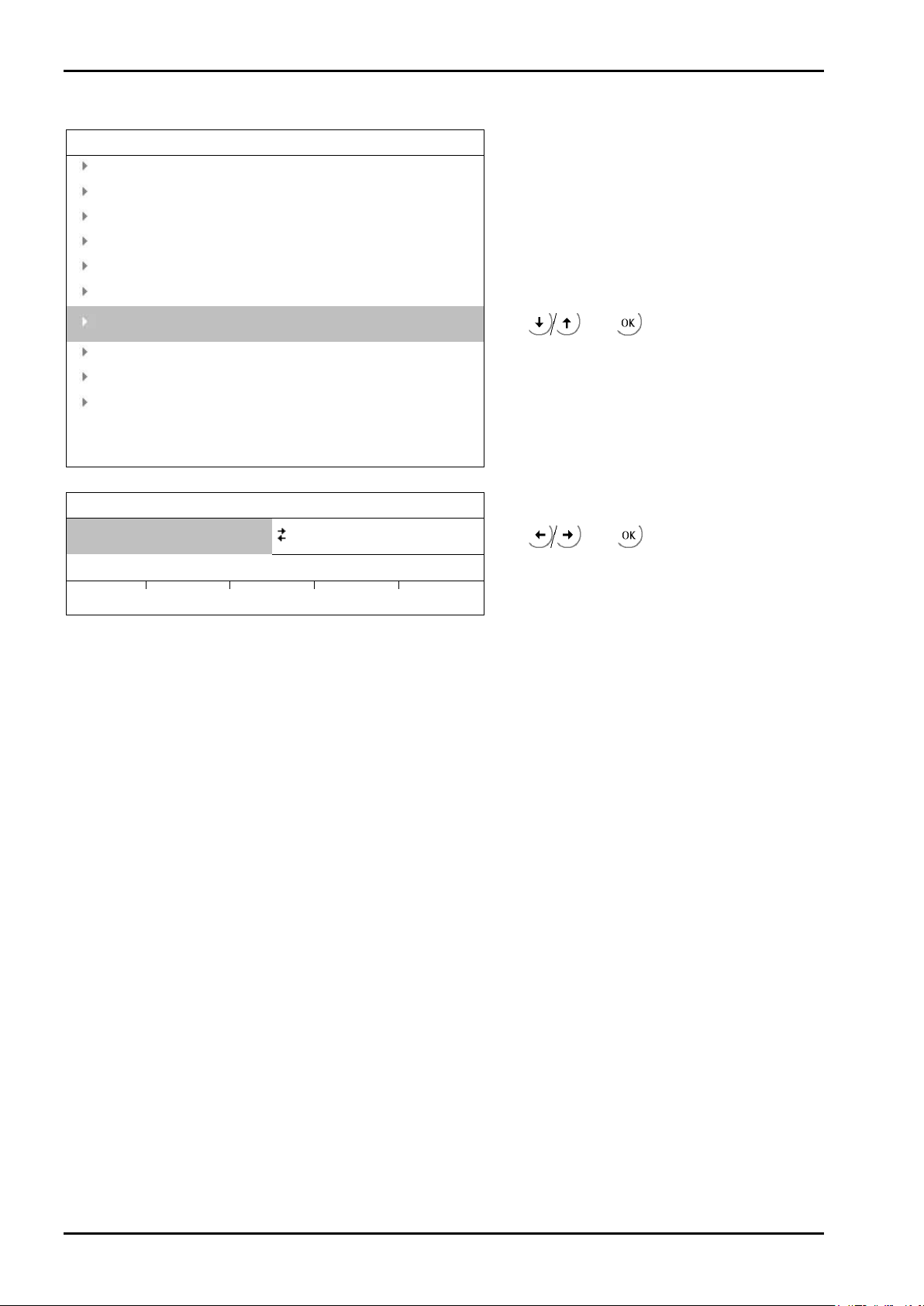
Commissioning
Setup
Serial ports parameter
Date & Time
Operating parameter
Printing parameter
Fieldbus parameter
Network parameter
Limit parameter
[Weighingpoint].
Digital I/O parameter
Analog output parameter
Weighingpoint
[Pendeo Load Cells]
Assign
4.6.4 Selecting the Load Cell Type
PR 5220 Instrument Manual
Weighingpoint
Weighingpoint A
Setup
Config
Pendeo Load Cells
Param
Press and to select
Press and to select
EN-84 Sartorius
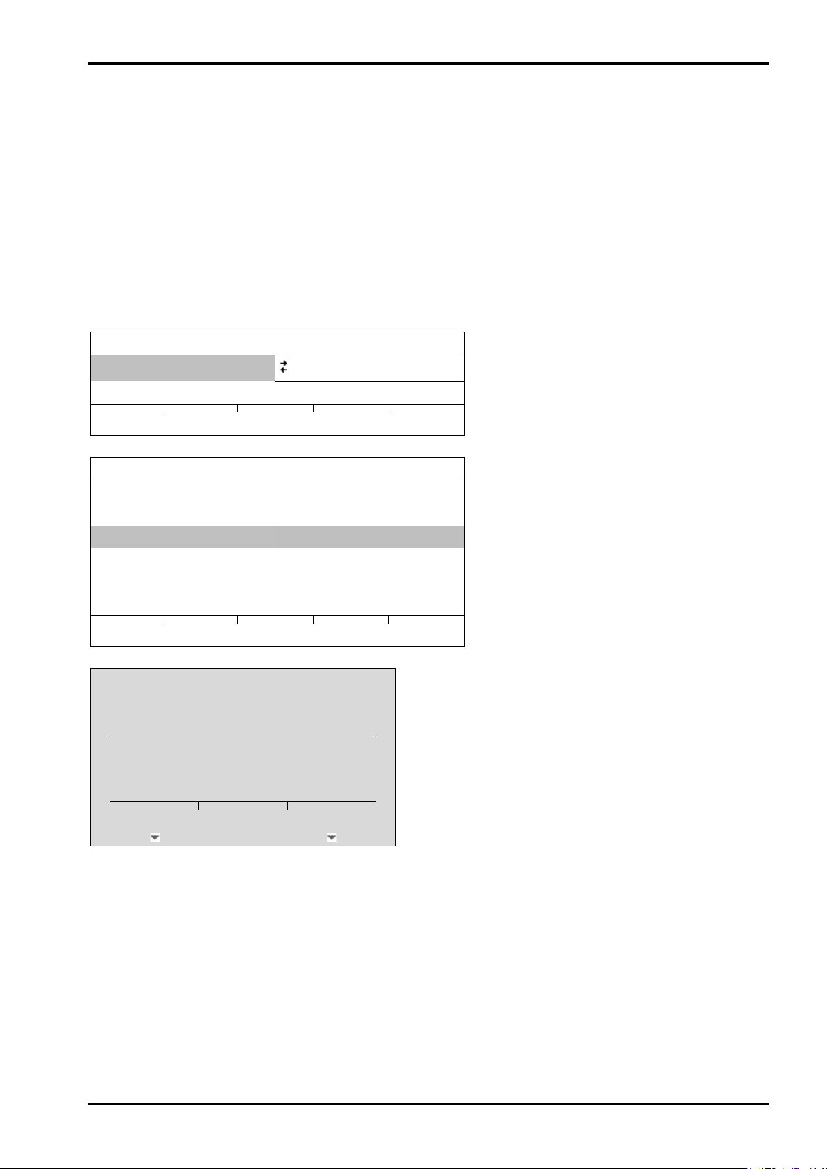
PR 5220 Instrument Manual Commissioning
Note:
For further information about calibrating weighing points, see Chapter 4.4.
Weighingpoint
Assign
Weighingpoint/WP A
Type
Pendeo process
No of LC
1
LC 1
0
Search
View
Calib
?
Cancel
Continue
4.6.5 Adjustment Sequence
During calibration, no data is changed in the digital load cells. The calibration data and parameters are saved
in the instrument. The unique serial numbers of the connected load cells are monitored.
For the adjustment is the following order specified:
• Search for load cells, see Chapter 4.6.6.
• Assign load cells, see Chapter 4.6.7.
• Calibrate ‘New’: Max with weight unit, scale interval, dead load, calibration weight, see Chapter 4.6.8.
4.6.6 Search for Load Cells
Weighingpoint A
Setup
Search for connected load cells.
Config
The actual settings are reset to
default.
Pendeo Load Cells
Param
Press [Assign].
Press [Search].
Press [Cancel] to accept and display the existing values.
Press [Continue] to start a new search process.
Sartorius EN-85
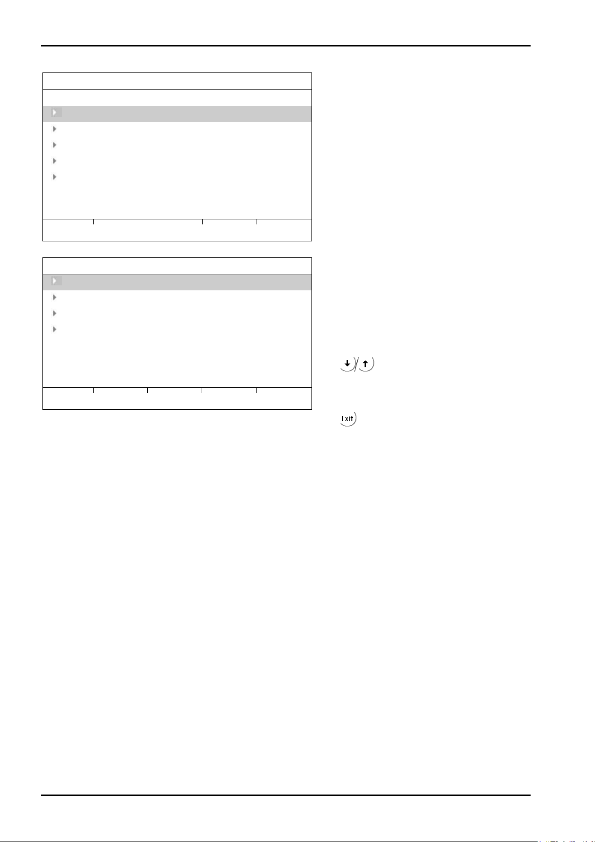
Commissioning
Load Cell Information
Type
Pendeo process
No of LC 4
Number of load cells
LC 1 101
LC 2 103
LC 3 104
LC 4 102
Search
View
Calib
Weighingpoint/WP A/View
LC 1
101
1.958 t
LC 2
103
2.118 t
LC 3
104
1.610 t
LC 4
102
1.828 t
Info
Assign
If necessary press [Assign] to assign the load
Weighingpoint/WP A
PR 5220 Instrument Manual
Load cell type
Load cell serial number
Press [View].
Load cell load
Press to select the desired load cell.
Press [Info] to display the load cell data.
Press
to return.
cells; see Chapter 4.6.7.
EN-86 Sartorius
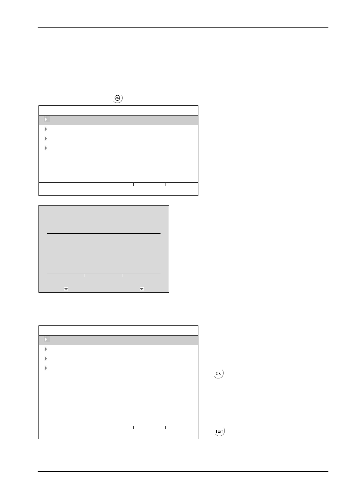
PR 5220 Instrument Manual Commissioning
Note:
Weighingpoint/WP A/View
LC 1
101
1.958 t
LC 2
103
2.118 t
LC 3
104
1.610 t
LC 4
102
1.828 t
Info
Assign
?
Cancel
Continue
Weighingpoint/WP A/View
Attach calibration weight to area of weighing
LC 1
101
1.958 t
1
LC 2
103
2.118 t
LC 3
104
1.610 t
LC 4
102
1.828 t
Info
Accept
4.6.7 Assigning Load Cells
The load cells (serial number) can be assigned to the place of installation in this menu. This is important for
correcting the dead load (distribution to the individual load cells), for corner correction and in the event of
load cell replacement.
The assignment from the installation should be documented in the case of load cells being
replaced.
Access the menu as follows: -[Weighingpoint]-[Assign]-[View].
Load cell load
Make sure to unload the scale.
Press [Assign].
WARNING!
Assigning the load cells
deletes the dead load
information!
Press [Continue] to reset the dead load information.
Press [Cancel] for no assigning start.
The load cells are assigned by placing minimum weights (50 kg) on the scale.
construction to be assigned to load cell No 1.
As soon as the device detects the weight
change, the corresponding line is selected.
Confirm the assigning of the 1st load cell
with
The future LC no. appears at the far right of the
line.
Remove the weight.
Repeat these steps for load cells 2–4.
Press the [Accept] soft key.
.
Press to return.
Sartorius EN-87
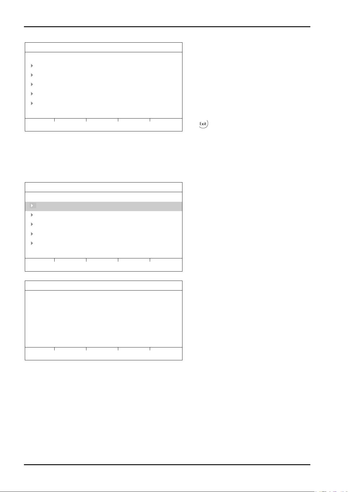
Commissioning
Weighingpoint/WP A
Press the [View] soft key.
Type
Pendeo process
No of LC 4
LC 1 101
LC 2 103
LC 3 104
LC 4 102
Search
View
Calib
Note:
[Modify] may be used only for minor changes (e.g. changing the dead load); otherwise, always use
Weighingpoint/WP A
Type
Pendeo process
No of LC 4
LC 1 101
LC 2 103
LC 3 104
LC 4 102
Search
View
Calib
Weighingpoint/WP A/Calibration
Number of vessel feet
4
Local gravity
9.81379 m/s2
Max
10000 d
200.000 t
Max: the sum of the max. load cell capacity is
Scale interval
1 d
0.020 t
Dead load
CAL weight
New
Modify
Param
4.6.8 Calibrating Load Cells
[New].
PR 5220 Instrument Manual
The new assignment will be displayed.
Check the corner load (dead load); see
Chapter 4.6.9.2.
Press to return.
When you press [New], the data is set to default first and calibration is started.
Press [Calib].
preset (4x 50 t = 200 t).
Press [New].
EN-88 Sartorius

PR 5220 Instrument Manual Commissioning
?
Yes No
Weighingpoint/WP A/Calibration
Parameter input:
Number of vessel feet
4
Number of vessel feet (in the case, 4).
Local gravity
9.81379 m/s2
Max
10000 d
200.000 t
Max. weight
Scale interval
1 d
0.020 t
Scale interval
Dead load
Dead load: empty scale
CAL weight
Calibrating weight
Corner correction
Corner correction
Corner correction will be reset.
Press [No] for no corner correction reset.
Press [Yes] to reset the corner correction and calibrating continues.
Local gravity
[Number of vessel feet]
Enter number of vessel feet.
[Local gravity]
2
Enter local gravity (in this case: Hamburg 9.81379 m/s
http://www.ptb.de/cartoweb3/SISproject.php.
[Max]
The load cell capacity is suggested as Max (E
The maximum capacity (Max) determines the maximum measured weight without dead load. Normally, the
selected Max must be smaller than the load cell capacity (nominal load * number of load cells) – dead load, in
order to prevent overloading the load cells.
Adapt the value for Max. When entering Max, the required number of digits behind the decimal point must be
taken into account. Press
[Scale interval]
Select the scale interval (1, 2, 5, 10, 20 or 50). The number of intervals is calculated and fed back
automatically.
to switch units.
* number of load cells).
max
); see e.g.
Sartorius EN-89

Commissioning
Weighingpoint/WP A/Calibration
Number of vessel feet
4
Local gravity
9.81379 m/s2
Max
10000 d
200.000 t
Scale interval
1 d
0.020 t
Dead load
CAL weight
by load
by value
7.511 t
Ok
Cancel
10.000 t
Ok
Cancel
[Dead load]
Empty weight as dead load
To use the empty scale/hopper as dead load (normal case):
• Discharge the scale/vessel.
• Press [by load].
The device must now display 0.000.
Known weight value as dead load
To use the known weight value as dead load:
• Press [by value].
An input window appears:
PR 5220 Instrument Manual
Enter input weight deadload
• Enter the known weight value and press [Ok].
The device must now display 0.000.
[CAL weight]
Press
Place CAL weight
and an input window appears.
on the scale and
enter value
Center the calibration weight on the scale and enter the weight value. Press the [OK] soft key.
Remove the calibration weight.
[Corner correction]
Carry out a corner correction if necessary, see Chapter 4.6.9.
Increased Resolution (10-fold)
During calibration press
5 seconds. Press
EN-90 Sartorius
to display the weight with 10-fold resolution. The resolution is reset after approx.
if you want to switch to normal resolution immediately.

PR 5220 Instrument Manual Commissioning
Weighingpoint/WP A/Calibration
Number of vessel feet
4
Local gravity
9.81379 m/s2
Max
10000 d
200.000 t
Scale interval
1 d
0.020 t
Dead load 7.511 t
CAL weight
10.000 t
Param
Weighingpoint/WP A/Calibration/Corner correction
Set the calibration weight on an area of
LC 1 -0.008 t
LC 2 -0.008 t
LC 3 0.007 t
LC 4 0.008 t
Calc
4.6.9 Corner Correction
4.6.9.1 General Information
An asymmetric scale construction doesn’t need a corner correction. But the corner correction may be necessary
at a symmetric scale construction.
4.6.9.2 Checking Corner Load (Dead Load)
After assignment and calibration, the load cell positions have been defined clearly.
4.6.9.3 Software Corner Correction
If the corners are loaded in succession, the same value should be displayed on the device at all times. An
excessive deviation almost always means that the scale is tilted or indicates load cell force shunts.
If the signal deviations cannot be resolved by carefully leveling the scale, the software must be calibrated.
New
When all load cells have been loaded once, you can press [Calc] to complete the corner correction.
The total weight remains unchanged. Only the effect of the individual load cells is corrected.
When corner correction is completed, the marking [ok] is shown.
Press
Modify
to return.
Press [Modify] and .
weighing construction.
The position (in this case, LC 4) is selected.
After confirmation (indicated by
weight onto the next position. The sequence is
unimportant. The cursor indicates the next load
cell/weight position.
), put the
Sartorius EN-91

Commissioning
Unless all data were determined during calibration using [New] (e.g. dead load
Press [Save] to save changes in calibration data. If you press [Undo], changes
4.6.10 Finishing/Saving the Calibration
Press to complete the calibration.
not set / entered), the following prompt is shown:
After replying [Yes] to confirm and pressing , another prompt is displayed:
are not saved and the display returns to the selection menu for the weighing
points.
The Confirmation is displayed with:
PR 5220 Instrument Manual
Saving calibration
After quitting the menu, the following message is displayed:
Exit calibration
After finishing the calibration, set the CAL switch to the closed position; see also Chapter 4.1.1.
EN-92 Sartorius

PR 5220 Instrument Manual Commissioning
Weighingpoint/WP A/Calibration
W & M
none
Standstill time
0.50 s
Standstill range
1.00 d
Tare timeout
2.5 s
Zeroset range
50.00 d
4.6.11 Parameter Input
Ambient conditions
[Ambient conditions]
This parameter is used to define the ambient conditions of the scale.
Possible values: very stable condition, Stable condition, Unstable condition, Very unstable condition
[W & M]
Setting for operation in Legal-for-Trade mode.
Select [none], [OIML], [NTEP] (für USA) or [NSC] (for Australia), see Chapter 4.4.13.1.
[Standstill time]
The parameters [Standstill time] and [Standstill range] can be used to define the stability of the scale (stable
balance).
The [Standstill time] parameter is entered in seconds. The permitted range is 0.00…2 s.
The time can be entered from 0.00 to 2.00 seconds, but makes up at least one measurement time.
Very stable cond.
[Standstill range]
As long as the weight fluctuations remain within this range, the device is determined to be stable.
The [Standstill range] parameter is entered in “d.” The permitted range is 0.01…10.00 d.
For use in Legal-for-Trade mode, <1 d must be selected.
[Tare timeout]
Timeout for a tare/zeroset command that cannot be executed (e.g., due to mechanical instability of the scale,
incorrect filter setting, resolution too high, standstill condition too strict).
This parameter is given in seconds. The permitted range is 0.0…<2.5>…25 s.
At 0.0 s taring is only carried out when the scale is already stable.
[Zeroset range]
Determine a ±range around the zero point determined by the dead load during calibration; within this range
- the displayed gross weight can be set to zero by pressing the zero-setting key (or by a corresponding
external command), and
- automatic zero tracking is active.
Setting range: 0.00…10000.00 d
For use in Legal-for-Trade mode a value <2% of Max must be entered. Example: 60 d for 3000 e, class III.
Sartorius EN-93

Commissioning
Weighingpoint/WP A/Calibration
Zerotrack range
0.25
d Zerotrack step
0.25 d
Zerotrack time
1.0 s
Overload
9 d
Min
20 d
Range mode
Single range
[Zerotrack range]
Range within which the automatic zerotrack is balanced.
Setting range: 0.25…10000.00 d
For use in Legal-for-Trade mode a value of 0.25 d must be entered.
[Zerotrack step]
If a weight change exceeds the adjusted value, automatic tracking does not function any more.
Setting range for automatic tracking increments: 0.25... 10 d
For use in Legal-for-Trade mode a value of 0.25 d must be entered.
PR 5220 Instrument Manual
[Zerotrack time]
Time interval for automatic zero tracking.
Setting range: 0.0…25 s
At 0.0 s the tracking is switched off. For use in Legal-for-Trade mode a value of 1 s must be entered.
[Overload]
Weighing range above the maximum capacity (Max) without error message.
Setting range: 0…999900 d. For use in Legal-for-Trade mode a value of max. 9 d = e must be set.
[Min]
Minimum weight at which a print command can be triggered.
Setting range: 0…999900 d. For use in Legal-for-Trade mode a value of at least 20 d must be set.
[Range mode]
For scale range selection, see Chapter 4.4.13.2.
EN-94 Sartorius

PR 5220 Instrument Manual Commissioning
Weighingpoint/WP A/Calibration
Number of vessel feet
4
Select [Dead load] and see page 90.
Local gravity
9.81379 m/s2
Max
10000 d
200.000 t
Scale interval
1 d
0.020 t
Dead load 7.512 t
CAL weight 10 t
Corner correction
ok
4.6.12 Subsequent Dead Load Correction
If the vessel weight changes by an amount that is higher than the zero-setting range, e.g. due to dead load
reduction, dead load increase or mechanical changes, the functions for automatic zero tracking and manual
zero setting no longer work. To view the range which is currently being utilized for zero tracking or zero
setting, press
to the previous state:
Current zero set: 0.00001 t
If the full zero-setting range is already being utilized, you can still correct the dead load (CAL switch must be
open) without affecting other calibration data/parameters.
. This also activates 10-fold increased resolution of the weight value. Press again to return
Check the corner load, see Chapter 4.6.9.2.
Carry out a corner correction if necessary, see
Chapter 4.6.9.3.
Sartorius EN-95
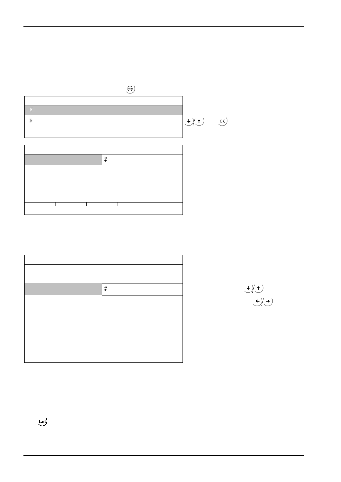
Commissioning
Setup
Serial ports parameter
Setup/Serial ports
SMA
none
Setup/Serial ports/Builtin RS485
Assigned to
Remote display
Protocol
Remote display
Parity
even
Stopbits
1
PR 5220 Instrument Manual
4.7 Configuring General Parameters
The configuration of parameters which are not related to the weighing electronics is divided into several
sections (see Chapter 4.3.8).
4.7.1 Serial Interfaces [Serial ports parameter]
To configure the serial interfaces, select -[Serial ports parameter].
Select [Serial ports parameter] with
Operating parameter
Remote display
Param
Config
Builtin RS485
and
Remote display protocol [Remote display]
Select the serial interface to which the remote display is connected and then select [Param] to define the
[Baudrate] and the remote display type [Mode] connected.
Baudrate
Bits 7
Mode multiple transmitters
Device ID A
Next Device ID B
9600 bd
Select [Baud rate] with
and set the baud rate with
.
Several remote displays are connected.
Address of the instrument
Next address of the instrument
You can only set the baud rate to 300, 600, 1200, 2400, 4800 or 9600. The other parameters (displayed in
light-gray) cannot be changed.
If only 1 instrument is connected to a remote display (normal case), [Mode] must be set to [single transmitter].
If more than 1 instrument is connected to 1 remote display, [Mode] must be set to [multiple transmitters].
At [Device Id] the own instrument address (A, B, C ...) has to be entered, at [Next Device Id] the address of the
subsequent instrument has to be entered
Press
to return to the menu ‚Serial ports’.
EN-96 Sartorius
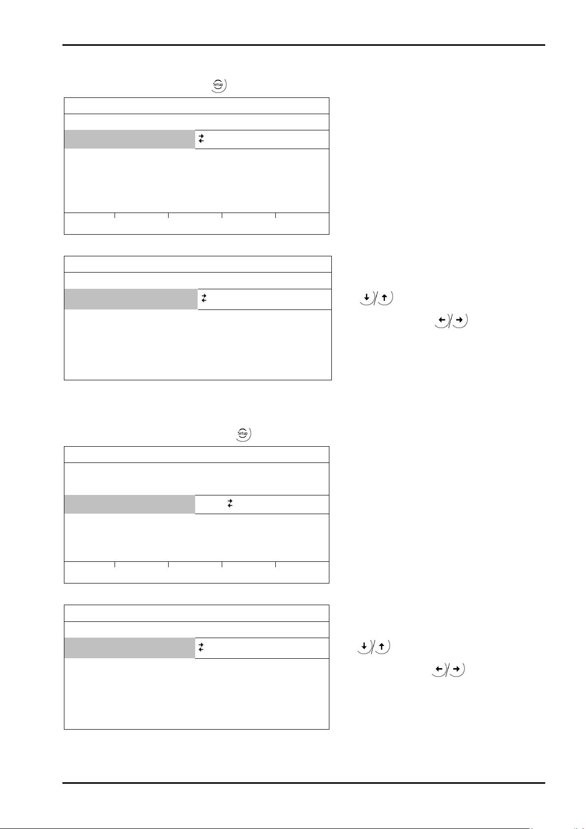
PR 5220 Instrument Manual Commissioning
Setup/Serial ports
Remote display
none
Param
Setup/Serial ports/Builtin RS485
Assigned to
SMA
Parity
none
Stopbits
1
Setup/Serial ports
Remote display
-none-
SMA
-none-
Param
Setup/Serial ports/Builtin RS485
Assigned to
xBPI-Port
Parity
odd
Stopbits
1
1, 2
SMA Protocol
Select an RS-485 interface under
-[Serial ports parameter].
SMA
Builtin RS485
Click [Param].
Only the baud rate is adjustable; the other parameters are fixed.
Baudrate
Bits 8
9600 bd
Press
set the baud rate with
to select [Baudrate] and
.
The SMA protocol is described in Chapter 4.8.
xBPI-Protokoll
To configure the serial interfaces, press
-[Serial ports parameter]-[ xBPI-Port] to select a RS-485 interface.
xBPI-Port
Builtin RS485
Click [Param].
Only the baud rate and the stop bits are adjustable; the other parameters are fixed.
Baudrate
Bits 8
9600 bd
Press
to select [Baudrate] and
set the baud rate with
.
Sartorius EN-97

Commissioning
Setup/Operating parameter
SetTareKey
tare & reset tare
SetZeroKey
only when not tared
Press [Yes] to save the data.
PR 5220 Instrument Manual
4.7.2 Operating Parameters
Define the basic operating parameters under -[Operating parameter].
AccessCode 0
[AccessCode]
The access code can be used to protect the [Setup] from unauthorized operation. Enter a number with up to 6
digits. As long as you are in this menu, the value can be overwritten as required. When [AccessCode] is set to 0,
no access code ist prompted.
[SetTareKey]
The SetTare function can be configured (VNC operation / Internet browser).
[tare & reset tare]: the scale is tared if it was not tared previously; otherwise, tare is reset.
[tare & tare again]: when you press the [Tare] key, the current value is stored in the tare memory and a net
weight of 0 is displayed.
[disabled]: The tare key has no function.
[SetZeroKey]
The SetZero function (VNC operation / Internet browser) can be limited to gross mode with [only when not
tared] or switch the scale to gross mode automatically with [reset tare on zeroset]. If the zero-setting key with
these settings has no effect, the configured zero-setting range (around the zero-point set with the dead load)
is already utilized due to a previous zero-setting operation and/or automatic zero setting.
[disabled]: The key has no function.
Closing the menu
To close the menu, press
. The following message is displayed:
Press [No] to close the menu without changing data.
EN-98 Sartorius
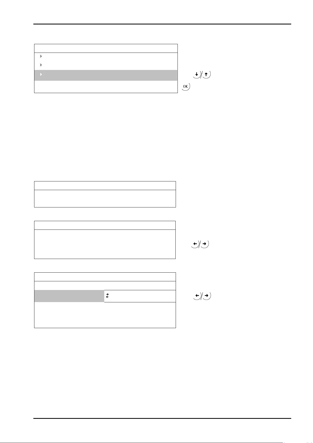
PR 5220 Instrument Manual Commissioning
Setup
Serial ports parameter
Operating parameter
Setup/Fieldbus parameter
Protocol
Profibus-DP
Profibus-DP Address
1
Enter address.
Setup/Fieldbus parameter
Protocol
DeviceNet
DeviceNet MAC-ID
1
Setup/Fieldbus parameter
Fieldbus protocol
ProfiNet I/O
IP address
192.168.1.1
Enter IP address.
Subnet mask
255.255.255.0
Enter Subnet mask.
4.7.3 Fieldbus Parameters
Fieldbus parameter
Press
to select [Fieldbus parameter]
and
This menu item can only be selected if the instrument is a PR 5220/01, a PR 5220/04, PR 5220/06 or
PR 5220/07 version.
The instrument version automatically determines the corresponding protocol:
- [Profibus-DP] for PR 5220/01
- [DeviceNet] for PR 5220/04
- [ProfiNet I/O] for PR 5220/06
- [EtherNet-IP] for PR 5220/07
Dependent on the interface type, additional parameters are required:
[Profibus-DP]
[DeviceNet]
DeviceNet baudrate 500k
[ProfiNet I/O]
Use DHCP
Press
address 1 ... 62.
off
Select
to select 500, 250 or 125 k.
on/off.
Sartorius EN-99

Commissioning
Setup/Fieldbus parameter
Fieldbus protocol
EtherNet/IP
IP address
192.168.1.1
Enter IP address.
Subnet mask
255.255.255.0
Enter Subnet mask.
Press [Yes] to save the data.
[EtherNet/IP]
PR 5220 Instrument Manual
Use DHCP
Closing the menu
To close the menu, press
off
Select
. The following message is displayed:
Press [No] to close the menu without changing data.
on/off.
EN-100 Sartorius
 Loading...