

Page 1
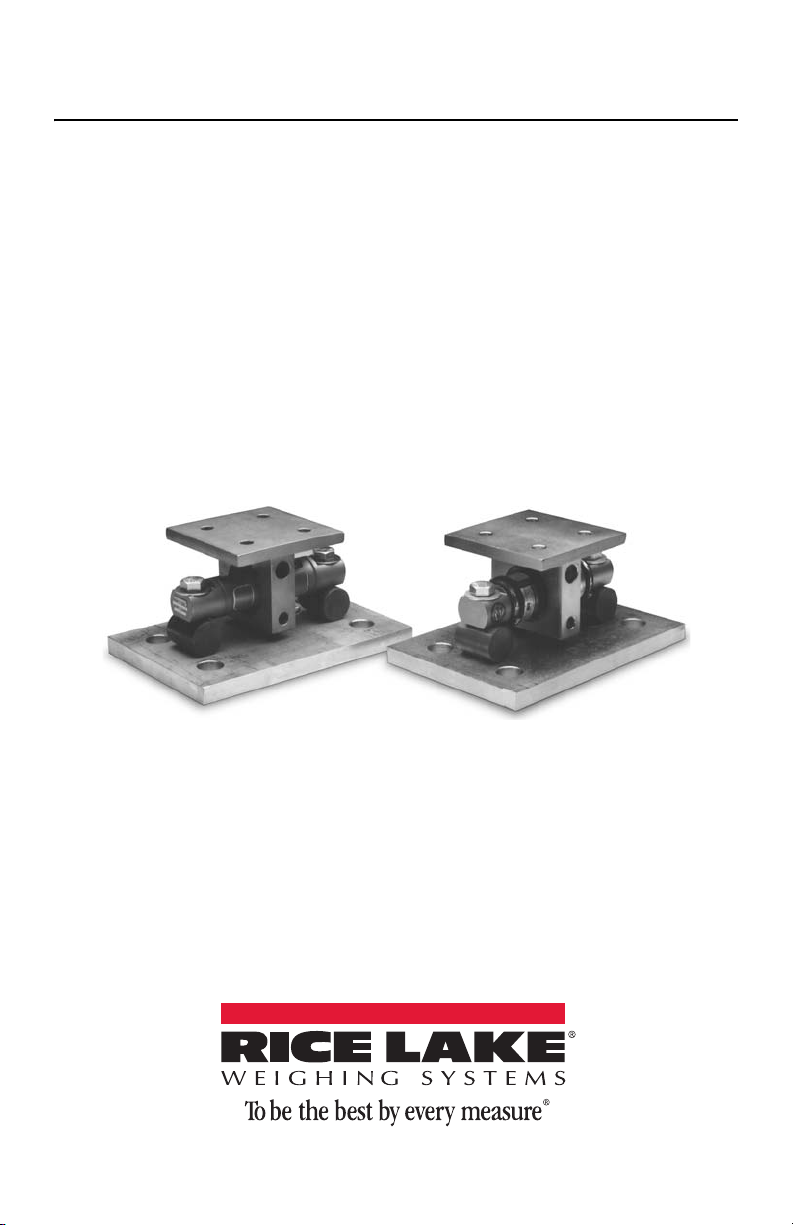
EZ MOUNT
Load Cell Mounting Kit
Installation
Guide
25710 Rev B
Page 2

Page 3

Technical training seminars are available through Rice Lake Weighing Systems.
Course descriptions and dates can be viewed at www.ricelake.com/training
or obtained by calling 715-234-9171 and asking for the training department.
Contents
1.0 Introduction . . . . . . . . . . . . . . . . . . . . . . . . . . . . . . . . . . . . . . . . . . 1
1.1 Safety . . . . . . . . . . . . . . . . . . . . . . . . . . . . . . . . . . . . . . . . . . . . . . . . 2
2.0 Mechanical Installation. . . . . . . . . . . . . . . . . . . . . . . . . . . . . . . . . 3
2.1 General Installation Guidelines for Tank Mounts . . . . . . . . . . . . . . 3
2.2 Installing the EZ Mount 1 . . . . . . . . . . . . . . . . . . . . . . . . . . . . . . . . 4
3.0 Load Cell Wiring . . . . . . . . . . . . . . . . . . . . . . . . . . . . . . . . . . . . . . 6
4.0 Junction Box Connections, Adjustments & Calibration . . . . . . . . 7
5.0 Troubleshooting . . . . . . . . . . . . . . . . . . . . . . . . . . . . . . . . . . . . . . . 8
6.0 Maintenance and Replacement Parts . . . . . . . . . . . . . . . . . . . . . . 9
EZ Mount Limited Warranty . . . . . . . . . . . . . . . . . . . . . . . . . . . . . . . .11
© Rice Lake Weighing Systems. All rights reserved. Printed in the United States of America.
Specifications subject to change without notice.
Rice Lake Weighing Systems is an ISO 9001 registered company.
March 10, 2014
Contents i
Page 4

ii EZ Mount Installation Guide
Rice Lake continually offers web-based video training on a growing selection
of product-related topics at no cost. Visit www.ricelake.com/webinars.
Page 5
1.0 Introduction
Thermal
Expansion
The EZ Mount 1 Load Cell Mounting Kit provides an extremely accurate method for
weighing medium and large capacity tanks and hoppers that are subject to large thermal expansion/contraction or vibration forces. The design uses a double ended shear
beam load cell (700Ω bridge) and transmits the load with a sliding pin on the loadbearing groove of the cell. This design is very effective in providing for thermal
expansion/contraction with little friction.
In the majority of applications, the assemblies are selfchecking and held captive with no need for check or stay
rods making this mount a good choice for areas with frequent seismic activity. The sliding pin design eases load
cell installation and replacement without the need to raise
the weighed vessel a large amount, which may disturb
piping and other connections.
The EZ Mount 1 is available in mild steel or stainless
steel in five sizes from 5,000-250,000 lb. The mount is compatible with RL70000 and
RTI 5103 mild steel load cells in capacities from 5,000 lb to 250,000 lb. The EZ
Mount 1 is also available in stainless steel with RL70000SS and RTI 9103 in capacities from 5,000 lb to 150,000 lb. The RL72010MH hermetically-sealed stainless steel
load cells are available in capacities from 5,000 lb to 60,000 lb.
Manuals can be viewed or downloaded from the Rice Lake Weighing
Systems website at
www.rlws.com.
Introduction 1
Page 6

1.1 Safety
WARNING
Important
WARNING
Safety Symbol Definitions:
Indicates a potentially hazardous situation that, if not avoided
could result in death or serious injury, and includes hazards that
are exposed when guards are removed.
Indicates information about procedures that, if not observed,
could result in damage to equipment or corruption to and loss of
data.
General Safety
Do not install or work on this equipment unless you have read and
understand the instructions and warnings in this manual. Failure to
follow the instructions or heed the warnings could result in injury or
death. Contact any Rice Lake Weighing System dealer for
replacement manuals. Proper care is your responsibility.
Failure to heed may result in serious injury or death.
The installation should be planned by a qualified structural engineer. Each installation is unique, and this manual is meant to serve only as a general guideline for
installation.
DO NOT use for purposes other than weight measurement.
DO NOT use any load-bearing component that is worn beyond 5% of the original
dimension.
DO NOT use this product if any of the components are cracked.
DO NOT exceed the rated load limit of the unit.
DO NOT make alterations or modifications to the unit.
Contact Rice Lake Weighing Systems for replacement manuals. Proper care is
your responsibility.
2 EZ Mount Installation Guide
Page 7

2.0 Mechanical Installation
Level - 0.5
Flexible Piping
J-Box
2.1 General Installation Guidelines for Tank Mounts
1. The mounting surface for the base and top plate must be level. After installation,
the top and bottom plates must be level within ±0.5°. If the mounting surfaces are
not level, then shims and or grout may be used to level the mount.
If possible, check that the mount is level when the vessel is fully loaded because
excessive deflections in legs and supporting structures may cause additional side
forces which greatly affect accuracy. Deflection of the mount’s top or base plate
due to loading should not exceed ±0.5°. Reinforcement of legs or other support
structures may be necessary to correct this. Vessels with long legs should have
cross bracing applied between adjacent legs to keep them from spreading under
load.
2. Compression mounting systems use three, four, or more mounts. More than
eight-mount systems should be avoided as even weight distribution becomes
extremely difficult to achieve. The load on each mount assembly should vary by
no more than 20%. Add shims where necessary to achieve correct load distribution.
3. If the actual load cells are used
during installation, take extreme care
to prevent overload damage. A tank
or hopper can exert huge forces
when dropped only a fraction of an
inch. Dummy load cells can be used
during installation.
4. It is crucial that all piping or conduit
be horizontal and flexible. If flexible
piping is not used, make sure distance from vessel to the first pipe
support is 20-30 times pipe diameter. For details, see the “Technical Information”
section of the RLWS Load Cell Product Selection Guide (PN 22054). In smaller,
lower capacity tanks and hoppers, isolating resultant forces becomes extremely
critical.
5. Load cells should not be installed in mounts until all welding is completed. The
heat generated from welding current passing through a load cell can damage the
adhesive holding the strain gauge to the body. If possible, use a dummy load cell
when welding to maintain finished height. If welding is unavoidable after load
cell installation, connect the ground in such a way that the current does not flow
through the load cell. For example, if welding on the mount top plate, the ground
must be connected to the vessel, not to the mount base or support structure. Also,
protect the load cell and cable from weld splatter.
6. Use only “hermetically sealed” RL72010MH load cells in washdown applications. “Environmentally protected” load cells are not suitable for such applications and will be damaged. If tanks and surrounding equipment are frequently
steam cleaned or if the load cell is subjected to direct washdown, a protective
shroud for the weighing assembly is recommended. Proper drainage is necessary
so the weighing assembly is not standing in water.
7. All support points should be equally stiff so that they deflect by the same amount
as the vessel is loaded.
Mechanical Installation 3
Page 8

Figure 8-1. Parts Illustration
Top Plate
Loading Bracket
Cotter Pin
Load Cell Bolt
Load Cell
Cotter Pin
Base Plate
Load Pin
Locating Pin
Washer
Load Bar
2.2 Installing the EZ Mount 1
1. The type of installation and strength of the mounting surface governs the method
of locating, attaching, and assembling the EZ Mount 1 assembly. Carefully consider three areas which commonly cause accuracy problems:
• Are the supporting legs adequately braced so they will not spread when the
system is fully loaded?
• Does the supporting structure have the necessary strength to prevent excessive
deflection when the system is fully loaded?
• Is there attached equipment such as skirting, venting, or piping which is likely
to cause binding or lack of flexibility?
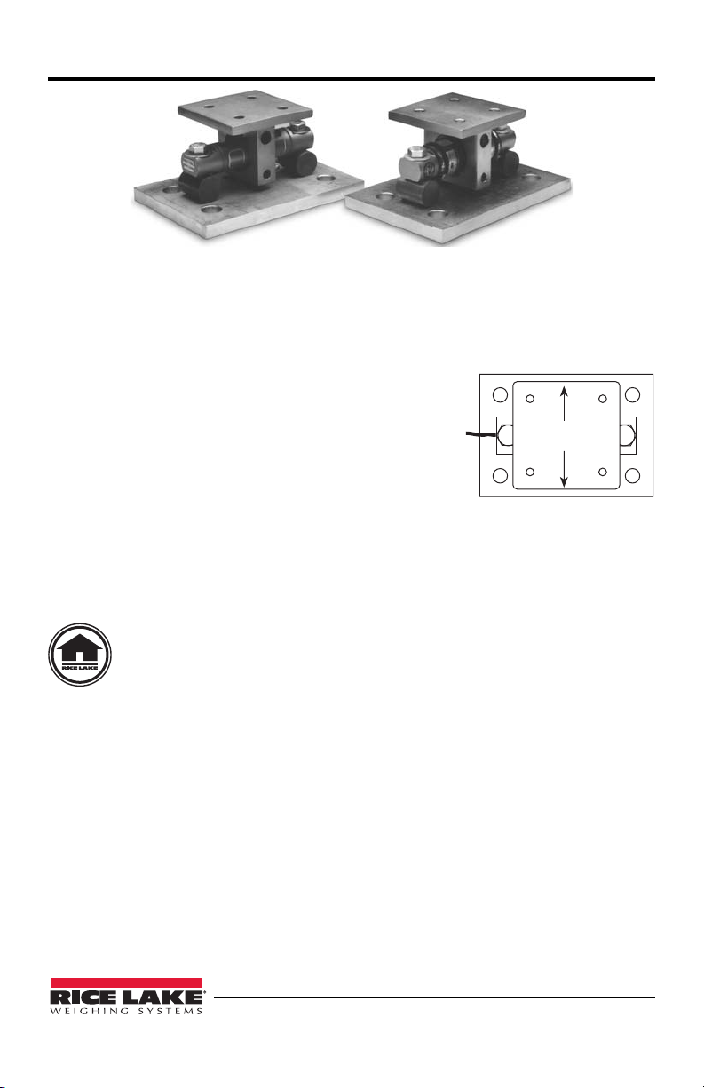
2. Determine where to position the mount and in which direction it should be oriented. The EZ Mount 1 is designed to allow for lateral movement in the direction
perpendicular to the longitudinal axis of the load cell. These tank weighing units
should be oriented so that the movement due to thermal expansion/contraction is
perpendicular to the longitudinal axis. Sample mounting orientations to accommodate expansion for different vessel shapes are as follows:
4 EZ Mount Installation Guide
Page 9

3. Assemble the mounts by inserting either a dummy load cell or the actual LOAD
Note
CELL into the hole in the TOP PLATE LOADING BRACKET then installing
the LOAD PIN and LOCATING PIN*. The LOAD CELL BOLTS are then
passed through the ends of the LOAD CELL and LOAD BARS and threaded into
the BASE PLATE and hand tightened.
The arrow on the load cell should point in the direction of the load.
4. Lift and block the vessel to the same height as the assembled mounts.
5. Remove the block from one support point and slide that mount into position.
6. If the mount is being fitted under the leg of a vessel, verify that the leg’s center
line passes through the center of the top plate (through the center of the load cell).
7. Lower the corner or side of the vessel carefully onto the top plate. The force of a
vessel weighing several tons can damage a load cell if dropped only a fraction of
an inch.
8. With the top plate positioned approximately level, mark holes for attaching the
top plate to the vessel’s mounting surface. Drill holes and attach top plate loosely
to vessel with suitable fasteners.
9. Repeat steps 4-10 for the mounting assemblies at the remaining corners or sides.
10. Verify that there is no initial misalignment between the BASE PLATE and TOP
PLATE and that the LOAD CELL is in the center of the hole in the TOP PLATE
LOADING BRACKET. Relocate if necessary.
11. Attach the base plates to the foundation using suitable anchors for concrete or by
bolting or welding to a steel structure. Verify that the base plates are no more than
±0.5° out of level. Shim as necessary.
12. Check that the top plates are no more than ±.5° out or level. Shim if necessary
and fully tighten mounting bolts.
13. If dummy cells are used, replace with actual LOAD CELLS. Refer to step 4.
14. To achieve equal load distribution, final height adjustments can be made with
shims between the TOP PLATE LOADING BRACKET and the weighing vessel.
The variation in load among the cells should be no more than 20%. The load distribution can be checked accurately by exciting each load cell in turn and measuring the output with a voltmeter.
15. Check that the bolts securing the load cell to the BASE PLATE are tight. Torque
the LOAD CELL BOLTS to only 20 foot-pounds. This allows the double-ended
load cell to flex under load.
Mechanical Installation 5
Page 10

3.0 Load Cell Wiring
Drip
Loop
1. Route the load cell cables so they will not be damaged or cut. Cable should not be
routed near heat sources greater than 150 °F. Do not shorten any load cell cable.
The load cell is temperature compensated with the supplied length of cable. Cutting the cable will affect temperature compensation. Coil and protect excess
cable so it will not be mechanically damaged or be sitting in water.
2. Provide a drip loop in all cables so that water or other liquids will not run directly
down the cables onto either the load cells or the junction box. Attach load cell
cable to the dead structure, not the vessel.
3. If conduit protection is necessary against mechanical or rodent damage to the
load cell cables, use flexible conduit and conduit adapters at the load cells. Conduit can also provide protection against moisture ingress into the load cell.
4. Connect cables for standard RL70000, RL70000SS, RTI 5103, RTI 9103 load
cells or RL72010MH hermetically sealed load cells to the summing board in the
junction box according to the guide shown below and the labels on the terminal
strips of the junction box. To verify the wiring scheme, see the certification
shipped with each load cell.
5. For better performance, use positive and negative remote sense lines if the wiring
running from the junction box to the indicator is longer than 25 feet.
Load Cell Wire Color Function
Red +EXC
Black –EXC
Green +SIG
White –SIG
Gray or Bare SHIELD
6 EZ Mount Installation Guide
Table 1: Load Cell Wiring
Page 11

4.0
Junction Box Connections, Adjustments & Calibration
1. Refer to Junction Box manual for trimming details.
2. Refer to indicator manual or “Technical Information” section in Rice Lake
Weighing Systems’ Load Cell Product Selection Guide (PN 22054) for system
calibration details.
Junction Box Connections, Adjustments & Calibration 7
Page 12

5.0 Troubleshooting
If the system powers up and gives some type of stable digital readout that varies with
the load on the system, any system problems are probably caused by factors other
than the load cells. The load cells are often blamed for a malfunctioning system, but
90% of the time, the problem lies elsewhere. Look for mechanical causes for your
problem first.
If the system can be calibrated but doesn’t return to zero, loses calibration, or demonstrates non-linearity or non-repeatability, see the following chart for possible causes
and do the following checks.
1. Check load cell mount for debris restricting load cell movement or debris
between scale and structure.
2. Check that tank/vessel and mounts are plumb, level, and square at critical areas.
3. Check all piping and conduit for connections which restrict vessel movement.
Symptom Possible Cause
No return to zero Mechanical binding or debris in seals or under load cells
Non-linearity Thermal expansion or deflection under load causing binding
Non-repeatability Loose load cell mount
Lost calibration Out of level or plumb
Drifting readout Moisture in junction box, cables or load cells
May have lost system calibration
or side load.
Drifting caused by moisture
Load cell overload or shack damage
Mechanical binding
Moisture problem
Mechanical binding
Mechanical binding
Table 1: Troubleshooting Chart
4. If check rods are used, loosen all connections to finger tight only for testing.
5. Check load cell cables for physical or water damage.
6. Check all electrical connections, especially in the junction box.
If the problem still is not found:
7. Check possible indicator malfunction by using a load cell simulator to input a
known good signal into the indicator.
8. Disconnect each load cell’s signal leads at the junction box and check individual
load cell outputs with a multimeter. Then check input/output impedances for
comparison with load cell manufacturer’s specifications.
If after all these checks the problem still cannot be isolated, reconnect all but one load
cell. Replace load cell with a load cell simulator. Alternate so that each load cell is
individually disconnected and replaced with a simulator. If there is a problem with a
particular load cell, the symptom should disappear when that load cell is disconnected
and replaced with simulator.
8 EZ Mount Installation Guide
Page 13

6.0 Maintenance and Replacement Parts
1
2
3
4
5
6
7
8
9
EZ Mount 1 Mild Steel Mounts
Item
No.
1 Top Plate Loading
2 Load Cell Bolt 2 14773 14795 14797 14797 26071
3 Washer 2 15177 15184 15184 15184 26070
4 Double-Ended Shear
5 Load Bar 2 18267 18268 18269 18269 26073
6 Base Plate 1 18264 18265 81266 82166 26074
7 Load Pin 1 18270 18271 18272 18272 26067
8 Locating Pin 1 18261 18262 18263 18263 26076
9 Cotter Pins 2 15229 15251 15257 15257 26069
10 JB4SS Junction Box (30 to
Description Qty Replacement Part Numbers
A* B* C* D* E*
1 18273 18274 18275 29014 26061
Bracket
1 See Load Cell Selection Guide
Beam Load Cell
107700
250K Capacity Kits)
Table 1: Mild Steel Mount Parts List
Maintenance and Replacement Parts 9
Page 14

EZ Mount 1 Stainless Steel Mounts
Item
No.
1 Top Plate Loading Bracket 1 18376 18377 18378 29013
2 Load Cell Bolt 2 14774 14796 14798 14798
3 Washer 2 15178 15187 15187 15187
4 Double-Ended Shear Beam
Load Cell
5 Load Bar 2 18267 18268 18269 18269
6 Base Plate 1 18370 18371 18372 18372
7 Load Pin 1 18270 18271 18272 18272
8 Locating Pin 1 18373 18374 18375 18375
9 Cotter Pins 2 15230 15252 15258 15258
10 JB4SS Junction Box (30 to 250K
Capacity Kits)
*A-size mounts use load cells with capacities from 5,000-20,000 lb.
*B-size mounts use load cells with capacities from 30,000-60,000 lb.
*C-size mounts use load cells with a capacity of 100,000 lb.
*D-size mounts use load cells with a capacity of 150,000 lb.
*E-size mounts use load cells with a capacity of 200,000 lb. and 250,000 lb.
Description Qty Replacement Part Numbers
A* B* C* D*
1 See Load Cell Selection Guide
107700
Table 2: Stainless Steel Mount Parts List
10 EZ Mount Installation Guide
Page 15

EZ Mount Limited Warranty
Rice Lake Weighing Systems (RLWS) warrants that all RLWS brand load cells properly installed by a Distributor or Original Equipment Manufacturer (OEM) will operate per written specifications. All load cell products are warranted against defects in
materials and workmanship for two (2) years. Products marked as “waterproof” are
warranted against defects in materials and workmanship relating to moisture ingress.
RLWS warrants that the equipment sold hereunder will conform to the current written
specifications authorized by RLWS. RLWS warrants the equipment against faulty
workmanship and defective materials. If any equipment fails to conform to these warranties, RLWS will, at its option, repair or replace such goods returned within the
warranty period subject to the following conditions:
• Upon discovery by Buyer of such non-conformity, RLWS will be given prompt
written notice with a detailed explanation of the alleged deficiencies.
• Examination of such equipment by RLWS confirms that the non-conformity
actually exists, and was not caused by accident, misuse, neglect, alteration,
improper installation, improper repair or improper testing; RLWS shall be the
sole judge of all alleged non-conformities.
• Such equipment has not been modified, altered, or changed by any person
other than RLWS or its duly authorized repair agents.
• RLWS will have a reasonable time to repair or replace the defective equip-
ment. Buyer is responsible for shipping charges both ways.
• In no event will RLWS be responsible for travel time or on-location repairs,
including assembly or disassembly of equipment, nor will RLWS be liable for
the cost of any repairs made by others.
THESE WARRANTIES EXCLUDE ALL OTHER WARRANTIES, EXPRESSED
OR IMPLIED, INCLUDING WITHOUT LIMITATION WARRANTIES OF MERCHANTABILITY OR FITNESS FOR A PARTICULAR PURPOSE. NEITHER
RLWS NOR DISTRIBUTOR WILL, IN ANY EVENT, BE LIABLE FOR INCIDENTAL OR CONSEQUENTIAL DAMAGES.
RLWS AND BUYER AGREE THAT RLWS’S SOLE AND EXCLUSIVE LIABILITY HEREUNDER IS LIMITED TO REPAIR OR REPLACEMENT OF SUCH
GOODS. IN ACCEPTING THIS WARRANTY, THE BUYER WAIVES ANY AND
ALL OTHER CLAIMS TO WARRANTY.
SHOULD THE SELLER BE OTHER THAN RLWS, THE BUYER AGREES TO
LOOK ONLY TO THE SELLER FOR WARRANTY CLAIMS.
No terms, conditions, understanding, or agreements purporting to modify the terms of
this warranty shall have any legal effect unless made in writing and signed by a corporate officer of RLWS and the Buyer.
© Rice Lake Weighing Systems, Inc. Rice Lake, WI USA. All Rights Reserved.
RICE LAKE WEIGHING SYSTEMS • 230 WEST COLEMAN STREET
RICE LAKE, WISCONSIN 54868 • USA
Maintenance and Replacement Parts 11
Page 16

230 W. Coleman St. • Rice Lake, WI 54868 • USA
U.S. 800-472-6703 • Canada/Mexico 800-321-6703 • International 715-234-9171 • Europe +31 (0) 88 2349171
www.ricelake.com www.ricelake.mx www.ricelake.eu www.ricelake.co.in m.ricelake.com
© Rice Lake Weighing Systems 03/2014 25710 Rev B
 Loading...