

Page 1
MC-1000
MC-6100
1WMPD4002204
Page 2
This Manual and Marks
All safety messages are identified by the following, “
ANSI Z535.4 (American National Standard Institute: Product Safety Signs and
Labels). The meanings are as follows:
A potentially hazardous situation which, if not avoided,
WARNING
CAUTION
This is a hazard alert mark.
The contents of the product specifications and this manual are subject to
Under the copyright laws, the software (program) described in it are copyrighted,
Microsoft, Windows, Word and Excel are registered trademarks of the Microsoft
This manual is subject to change without notice at any time to improve the
product.
change without any obligation on the part of the manufacturer.
with all rights reserved.
The software may be installed into one computer and may not be installed into
other computers without the prior written consent of A&D Company. Copying
includes translation into another language, reproduction, conversion, photocopy
and offer or loan to another person.
Corporation.
2010 All rights reserved.
No part of this publication may be reproduced, transmitted, transcribed, or
translated into any language in any form by any means without the written
permission of A&D Company Ltd.
could result in death or serious injury.
A potentially hazardous situation which, if not avoided,
may result in minor or moderate injury.
WARNING
” or “
CAUTION
”, of
Page 3

CONTENTS
Basic Operation
1. INTRODUCTION .............................................................................................................................3
1-1 About This Manual .............................................................................................................................. 3
1-2 Features ............................................................................................................................................. 3
1-3 Compliance......................................................................................................................................... 3
2. UNPACKING THE BALANCE ........................................................................................................4
2-1 MC-1000............................................................................................................................................. 4
2-2 MC-6100............................................................................................................................................. 7
2-3 Installing the Balance ....................................................................................................................... 10
3. PRECAUTIONS ............................................................................................................................10
3-1 Before Use........................................................................................................................................ 10
3-2 During Use.........................................................................................................................................11
3-3 After Use........................................................................................................................................... 12
3-4 Power Supply ................................................................................................................................... 12
4. DISPLAY SYMBOLS AND KEY OPERATION..............................................................................13
5. WEIGHING ....................................................................................................................................14
5-1 Selecting the Weighing Units (Modes) ............................................................................................. 14
5-2 Basic Weighing................................................................................................................................. 14
Adapting to the Environment
6. RESPONSE ADJUSTMENT / SELF CHECK FUNCTION............................................................16
6-1 Automatic Response Adjustment / Self Check Function .................................................................. 16
6-2 Manual Response Adjustment.......................................................................................................... 17
7. CALIBRATION ..............................................................................................................................18
7-1 Calibration Group ............................................................................................................................. 18
7-2 Automatic Self Calibration (Calibration due to changes in temperature) ................................................ 19
7-3 Calibration Using the Internal mass (One-touch calibration)............................................................ 19
7-4 Calibration Using an External Weight............................................................................................... 20
7-5 Calibration Test Using an External Weight....................................................................................... 22
7-6 Correcting the Internal Mass Value .................................................................................................. 24
Functions
8. FUNCTION SWITCH AND INITIALIZATION.................................................................................26
8-1 Permit or Inhibit ................................................................................................................................ 26
8-2 Initializing the Balance...................................................................................................................... 27
9. FUNCTION TABLE .......................................................................................................................28
9-1 Structure and Sequence of the Function Table ................................................................................28
9-2 Display and Keys.............................................................................................................................. 28
9-3 Details of the Function Table ............................................................................................................ 29
1
Page 4

9-4 Description of the Class “Environment, Display” .............................................................................. 33
9-5 Description of the Item “Data output mode”...................................................................................... 34
9-6 Description of the Item “Data format” ............................................................................................... 35
9-7 Description of the Data Format Added to the Weighing Data........................................................... 37
9-8 Data Format Examples..................................................................................................................... 38
10. ID NUMBER AND GLP REPORT ............................................................................................... 39
10-1 Setting the ID Number .................................................................................................................... 39
10-2 GLP Report..................................................................................................................................... 40
RS-232C Serial Interface
11. RS-232C SERIAL INTERFACE / EXTERNAL INPUT.................................................................43
12. CONNECTION TO PERIPHERAL EQUIPMENT ........................................................................45
12-1 Connection to the AD-8121B Printer .............................................................................................. 45
12-2 Connection to a Computer.............................................................................................................. 46
12-3 Using Windows Communication Tools (WinCT)............................................................................. 46
13. COMMANDS...............................................................................................................................48
13-1 Command List................................................................................................................................. 48
13-2 Acknowledge Code and Error Codes ............................................................................................. 49
13-3 Control Using CTS and RTS .......................................................................................................... 50
13-4 Settings Related to RS-232C ......................................................................................................... 50
14. EXTENDED FUNCTION .............................................................................................................51
14-1 Description of "Averaging range" and "Averaging time"................................................................. 52
Maintenance
15. MAINTENANCE..........................................................................................................................54
16. TROUBLESHOOTING ................................................................................................................54
16-1 Checking the Balance Performance and Environment................................................................... 54
16-2 Error Codes .................................................................................................................................... 55
16-3 Asking For Repair ........................................................................................................................... 58
17. SPECIFICATIONS.......................................................................................................................59
18. OPTIONS ....................................................................................................................................60
19. EXTERNAL DIMENSIONS .........................................................................................................61
20. TERMS/INDEX............................................................................................................................62
2
Page 5

1. INTRODUCTION
This manual describes how the MC Series Mass Comparator Balances, MC-1000 and MC-6100,
work, and how to get the most out of them in terms of performance.
Read this manual thoroughly before using the balance and keep it at hand for future reference.
For other functions and operations that this manual does not describe, refer to the GX series
instruction manual.
1-1 About This Manual
This manual consists of the following five parts:
Basic operation ............................... Describes precautions on handling the balance, balance
construction and basic balance operation.
Adapting to the environment...........Describes response adjustment, calibration and calibration
test.
Functions ........................................ Describes various functions of the balance.
RS-232C serial interface................. Describes the interface which transmits data and controls the
balance.
Maintenance ...................................Describes maintenance, error codes, troubleshooting,
specifications and options.
1-2 Features
z Display resolution, one digit greater than a standard balance. This allows management of
OIML class F1 weights.
z Capable of weighing small amounts of powdery or liquid material, even with a massive tare.
z When used as a mass comparator, the balance can achieve even more precise weighing, by
using the optional auto-centering pan (sold separately), which reduces eccentric loading
errors.
1-3 Compliance
Compliance with FCC Rules
Please note that this device generates, uses and can radiate radio frequency energy. This
device has been tested and has been found to comply with the limits of a Class A computing
device pursuant to Subpart J of Part 15 of FCC rules. These rules are designed to provide
reasonable protection against interference when this device is operated in a commercial
environment. If this unit is operated in a residential area, it may cause some interference and
under these circumstances the user would be required to take, at his own expense, whatever
measures are necessary to eliminate the interference.
(FCC = Federal Communications Commission in the U.S.A.)
3
Page 6
2. UNPACKING THE BALANCE
z The balance is a precision instrument. Unpack the balance carefully. Keep the packing
material to be used for transporting the balance in the future.
z The packing contents depend on the balance model. See the illustrations to confirm that
everything is contained..
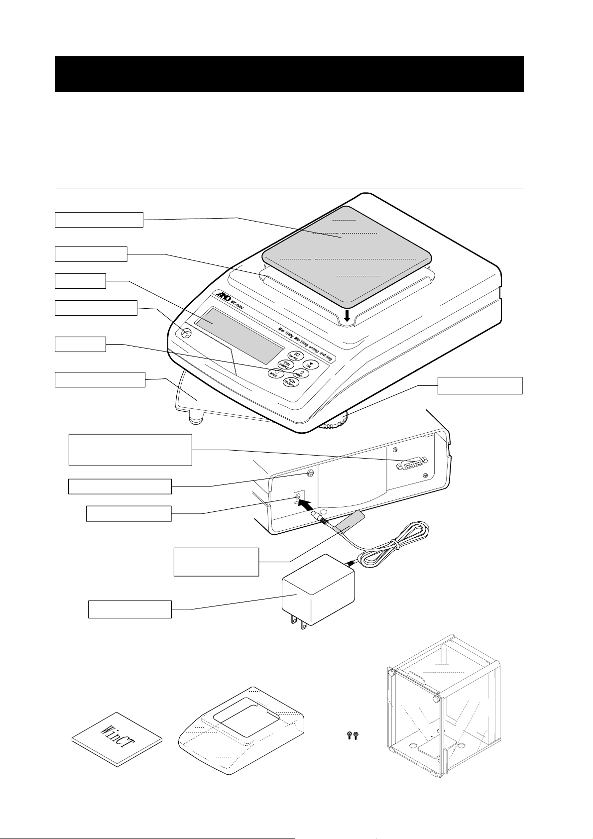
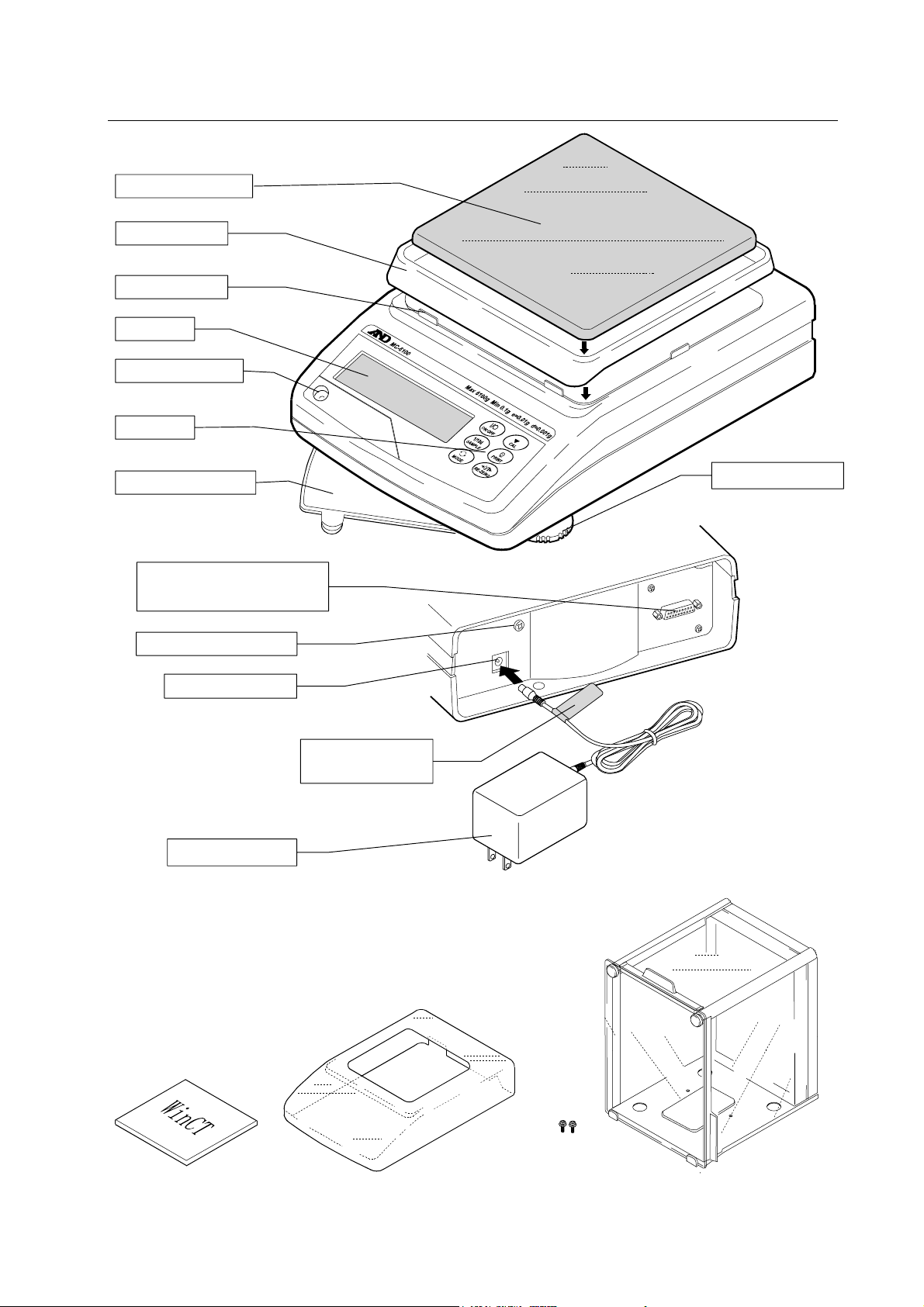
2-1 MC-1000
Weighing pan
Dust guard
Display
Bubble spirit level
Keys
Reference card
RS-232C serial interface
(External input terminal)
Grounding terminal
AC adapter jack
Main unit
Leveling foot
Main unit rear
AC adapter
Note
Please confirm that the AC adapter
type is correct for your local
voltage and receptacle type.
Windows Communication Tools
WinCT
AC adapter
ID label
Main unit cover
4
Breeze break
securing screw
(2 pieces)
Glass breeze break
Page 7
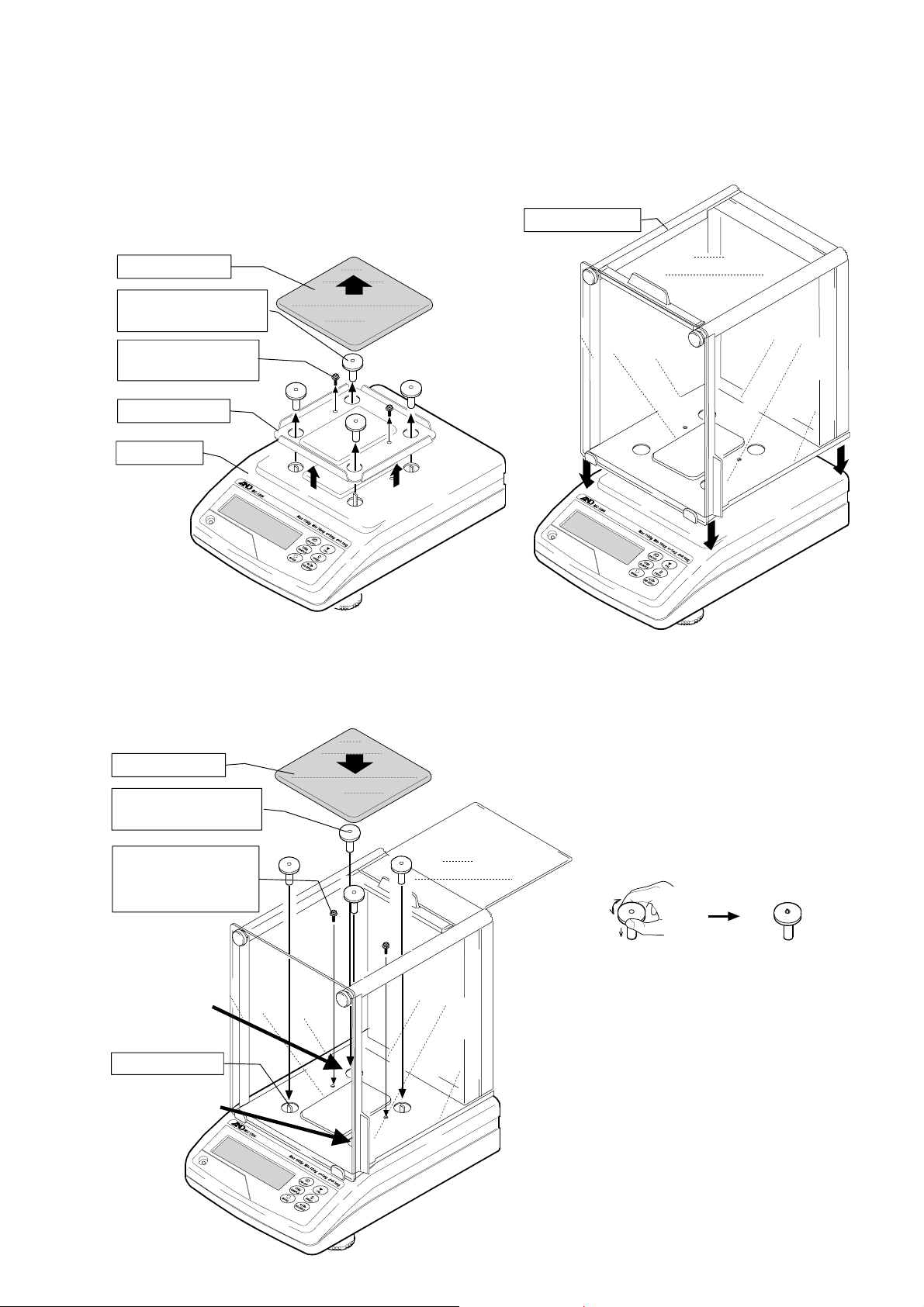
Glass breeze break installation procedure
(4 p
(2 p
t
t
(4 p
Caution: During installation, do not apply excessive force to the balance.
1. Remove the weighing pan, pan support
receptors, and dust guard from your balance.
To remove the dust guard, remove the two
screws that secure it to the balance.
Weighing pan
Pan support receptor
Dust guard securing
screw
Dust guard
Main unit
ieces)
ieces)
2. Place the breeze break on the main unit
Breeze break
3. Secure the breeze break to the main unit using
two screws provided with the breeze break.
Replace the pan support receptors and
weighing pan.
Weighing pan
Pan support receptor
ieces)
Breeze break
securing screw
(2 pieces)
Rear lef
• When installing the pan support
receptors at the front right and
rear left, note the following:
Push in the pan support receptors so
that the shock absorber springs are
above the receptor head surface. If
the pan support receptors are hard to
push in, hold the head of the receptor
as shown below and push it in while
rotating the head to the right and left.
• Keep the removed dust guard and
dust guard securing screws (2
pieces).
Shock absorber
Front righ
• To reinstall the dust guard after
removing the breeze break, use
the two screws to secure the dust
guard.
• The dust guard securing screws
and breeze break securing screws
are different in length.
5
Page 8
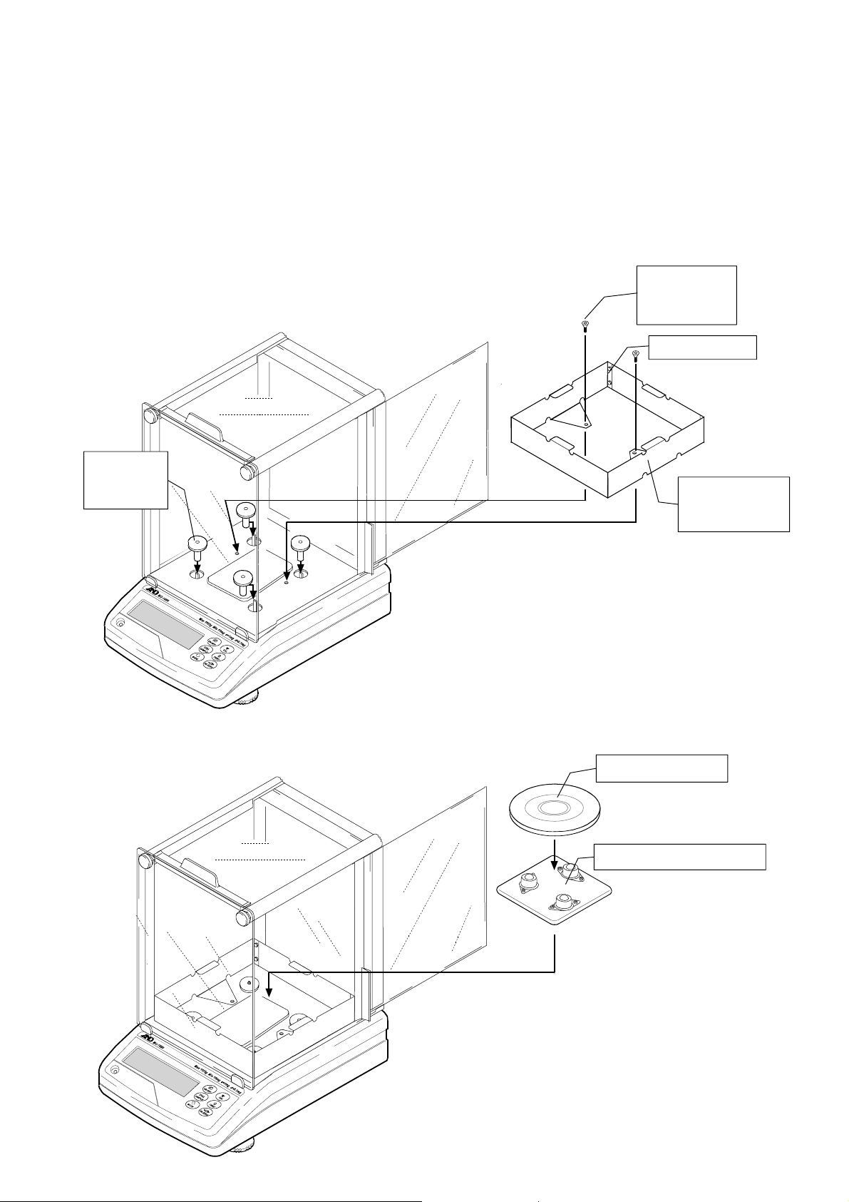
Auto-centering pan (AX-MC1000PAN) installation procedure
Caution: During installation, do not apply excessive force to the balance.
z When used as a mass comparator, the balance can achieve even more precise weighing,
by using the auto-centering pan (sold separately), which reduces eccentric loading errors.
1. At step 2 of the glass breeze break installation procedure, secure the breeze break provided with
the AX-MC1000PAN option using the breeze break securing screws provided with the option. At
this time make sure that the side of the breeze break with the screws is placed at the back.
Attach the pan support receptors to the shock absorbers.
Pan support
receptors
(4 pieces)
2. Place the auto-centering pan guide on the pan support receptors, and then place the
auto-centering pan on the guide.
Note
Breeze break
securing screw
(2 pieces)
Side with screws
Option
AX-MC1000PAN
breeze break
Auto-centering pan
Auto-centering pan guide
When replacing the weighing pan
with the auto-centering pan, be sure
to calibrate the balance before
weighing.
Refer to “7. CALIBRATION”.
6
Page 9
2-2 MC-6100
..
Weighing pan
Breeze ring
Dust guard
Display
Bubble spirit level
Keys
Reference card
RS-232C serial interface
(External input terminal)
Grounding terminal
AC adapter jack
Main unit
Leveling foot
Main unit rear
AC adapter
ID label
AC adapter
Note
Please confirm that the AC adapter
type is correct for your local
voltage and receptacle type
Windows Communication Tools
WinCT
Main unit cover
Breeze break
securing screw
(2 pieces)
Glass breeze break
7
Page 10

Glass breeze break installation procedure
(4 p
(2 p
t
t
(4 p
Caution: During installation, do not apply excessive force to the balance.
1. Remove the weighing pan, breeze ring, pan support
receptors, and dust guard from your balance.
To remove the dust guard, remove the two screws that
secure it to the balance.
Weighing pan
Breeze ring
Dust guard securing
screw
Pan support receptor
ieces)
ieces)
Dust guard
Main unit
2. Place the breeze break on the main unit
Breeze break
3. Secure the breeze break to the main unit using two
screws provided with the breeze break.
Replace the pan support receptors and weighing pan.
Weighing pan
Pan support receptor
ieces)
Breeze break
securing screw
(2 pieces)
Rear lef
Shock absorber
Front righ
• When installing the pan support
receptors at the front right and
rear left, note the following:
Push in the pan support receptors so
that the shock absorber springs are
above the receptor head surface. If
the pan support receptors are hard to
push in, hold the head of the receptor
as shown below and push it in while
rotating the head to the right and left.
• Keep the removed dust guard,
dust guard securing screws (2
pieces) and breeze ring.
• To reinstall the dust guard after
removing the breeze break, use
the two screws to secure the dust
guard.
• The dust guard securing screws
and breeze break securing screws
are different in length.
8
Page 11
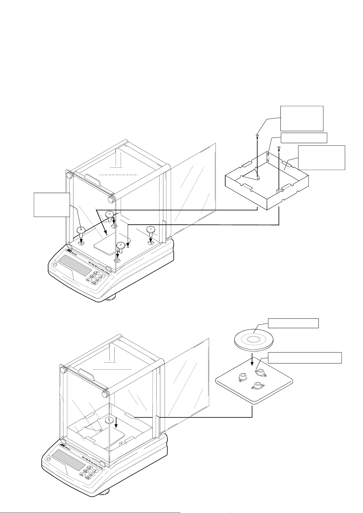
Auto-centering pan (AX-MC6100PAN ) installation procedure
Caution: During installation, do not apply excessive force to the balance.
z When used as a mass comparator, the balance can achieve even more precise weighing,
by using the auto-centering pan (sold separately), which reduces eccentric loading errors.
1. At step 2 of the glass breeze break installation procedure, secure the breeze break provided with
the AX-MC6100PAN option using the breeze break securing screws provided with the option. At
this time make sure that the side of the breeze break with the screws is placed at the back.
Attach the pan support receptors to the shock absorbers.
Pan support
receptors
(4 pieces)
2. Place the auto-centering pan guide on the pan support receptors, and then place the
auto-centering pan on the guide.
When placing on the pan
support receptors, tilt the
auto-centering pan guide
to the left and right,
forward and backward.
Note
Breeze break
securing screw
(2 pieces)
Side with screws
Option
AX-MC6100PAN
breeze break
Auto-centering pan
Auto-centering pan guide
When replacing the weighing pan with
the auto-centering pan, be sure to
calibrate the balance before weighing.
Refer to “7. CALIBRATION”.
9
Page 12

2-3 Installing the Balance
Install the balance as follows:
1. Refer to “3-1 Before Use” for installing the balance. Place the balance on a solid weighing
table.
2. Assemble the balance as shown in “2. UNPACKING THE BALANCE”.
3. Adjust the leveling feet to level the balance. Confirm it using the bubble spirit level.
4. Confirm that the adapter type is correct for the local voltage and power receptacle type.
5. Connect the AC adapter to the balance. Warm up the balance for at least 30 minutes with
nothing on the weighing pan.
3. PRECAUTIONS
To get the optimum performance from the balance and acquire accurate weighing data, note the
following:
3-1 Before Use
z The MC series is a high-precision balance with a resolution of
1/10000000. It is prone to changes in temperature and
pressure, static electricity, drafts and vibration of the installation
site. During calibration using an internal mass, it resolves up to
one digit lower than the minimum weighing value. Therefore, be
sure to place the balance in a stable environment.
z The best operating temperature is about 20°C±2°C at 45-60%
relative humidity.
z Install the balance where it is not exposed to direct sunlight and
it is not affected by heaters or air conditioners.
z Install the balance where it is free of dust.
z Install the balance away from equipment which produces
magnetic fields.
z Install the balance in a stable place avoiding vibration and
shock. Corners of rooms on the first floor are best, as they are
less prone to vibration.
z The weighing table should be solid and free from vibration,
drafts and as level as possible.
z Level the balance by adjusting the leveling feet and confirm it
using the bubble spirit level.
z If static electricity is a problem at the installation site, use the
electrostatic field meter and the static eliminator.
z Ensure a stable power source when using the AC adapter.
10
Page 13
z Warm up the balance for at least 30 minutes. Plug in the AC
adapter as usual.
z Calibrate the balance periodically for accurate weighing.
z Before using the balance for the first time or after having moved
it to another location, warm up the balance for six hours or
more to allow the balance to reach equilibrium with the room
temperature, and then calibrate the balance.
Caution
Do not install the balance where flammable or corrosive gas is present.
3-2 During Use
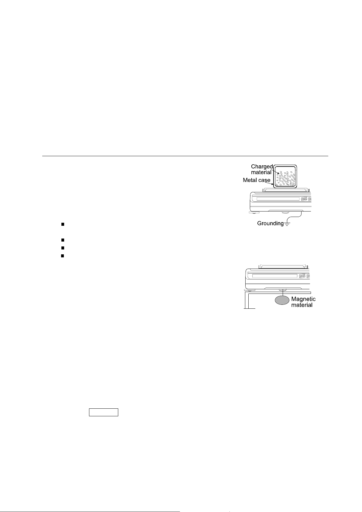
z Static charge may cause weighing errors. When the
ambient humidity is less than 45% RH, insulators such as
plastic or glass are prone to static electricity. Discharge
static electricity from the material to be weighed
(hereinafter referred to as sample). Ground the balance
and try the following:
Eliminate the static electricity by using an optional
static eliminator, AD-1683,
Or try to keep the ambient humidity above 45%RH.
Or use a metal shield case.
Or wipe a charged plastic sample with the wet cloth.
z This balance uses a strong magnet as part of the
balance assembly, so please use caution when
weighing magnetic materials such as iron. If there is a
problem, use the underhook on the bottom of the
balance to suspend the material away from the
influence of the magnet.
z Cancel the temperature difference between a sample, tare and the environment. When a
sample is warmer (cooler) than the ambient temperature, the sample will be lighter (heavier)
than the true weight. This error is due to a rising (falling) draft around the sample.
z Make each weighing gently and quickly to avoid errors due to changes in the environmental
conditions.
z Do not drop things upon the weighing pan, or place a sample on the pan that is beyond the
balance weighing capacity. Place a sample in the center of the weighing pan.
z Do not use a sharp instrument such as a pencil to press the keys. Use your finger only.
z Press the RE-ZERO key before each weighing to prevent possible errors.
z Take into consideration the affect of air buoyancy on a sample when more accuracy is
required.
z Keep the balance interior free of dust and foreign materials.
11
Page 14

3-3 After Use
z Avoid mechanical shock to the balance.
z Do not disassemble the balance. Contact the local A&D dealer if the balance needs service or
repair.
z Do not use organic solvents to clean the balance. Clean the balance with a lint free cloth that
is moistened with warm water and a mild detergent.
z Protect the internal parts of the balance from liquid spills and excessive dust.
3-4 Power Supply
z Do not remove the AC adapter while the internal mass is in motion, for example, right after the
AC adapter is connected, or during calibration using the internal mass.
If the AC adapter is removed under the conditions described above, the internal mass will be
left unsecured, that may cause mechanical damage when the balance is moved.
Before removing the AC adapter, press the ON:OFF key and confirm that zero is displayed.
z When the AC adapter is connected, the balance is in the standby mode if the standby indicator
is on (refer to “4. DISPLAY SYMBOLS AND KEY OPERATION”). This is a normal state and
does not harm the balance. For accurate weighing, warm up the balance for at least 30
minutes before use.
12
Page 15
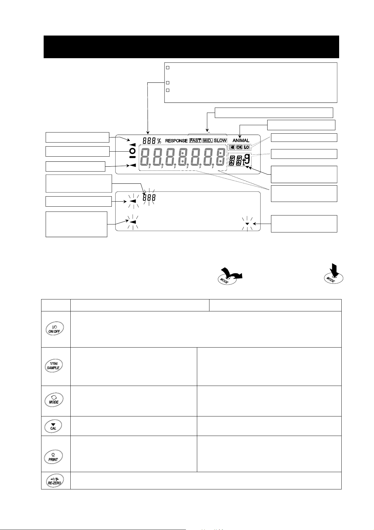
4. DISPLAY SYMBOLS AND KEY OPERATION
y
r
A
r
r
Display symbols
Processing indicator
Stabilization indicator
Standby indicator
Data number of the data
currently displayed
Processing indicator
Prior notice indicator
of automatic self
calibration
Displays the highest-order digit when placing a load of 1
kg or more on the MC-1000.
Displays data stored in memory.
Displays the weight data relative to the weighing capacity,
in percentage, in the weighing mode (Capacity indicator).
Response indicators (Weighing speed)
nimal mode indicato
Comparator indicators
Units
Interval memory
indicato
Blinking indicators
点滅中
standb
Weight data or
stored data
Interval memory
active indicato
Key operation
Key operation affects how the balance functions. The basic key operations are:
z “Press and release the key immediately” or “Press the key” z “Press and hold the key”
= normal key operation during measurement
Key When pressed When pressed and held
Turns the display on and off. The standby indicator is displayed when the display is turned
off. The weighing mode is enabled when the display is turned on.
This key is available anytime. Pressing the key during operation will interrupt the operation
and turn the display off.
Performs calibration of the balance using
In the weighing mode, turns the
minimum weighing value on and off.
In the counting or percent mode, enters
the sample storing mode.
No function at the factory setting
Switches the weighing units when units other
than “g” are stored in the function setting.
the internal mass.
Enters the function table mode. Refer to “9.
FUNCTION TABLE”.
Performs response adjustment and self check.
Displays calibration-related menu.
Stores the weighing data in memory or
outputs to a printer or personal computer
using the RS-232C interface (Factory
setting), depending on the function settings.
Sets the display to zero.
No function at the factory setting
By changing the function setting:
Outputs “Title block” and “End block” for GLP report.
Displays the data memory menu.
13
Page 16
5. WEIGHING
5-1 Selecting the Weighing Units (Modes)
The unit “g” (gram) was set at the factory.
To use other units, select and store units and displaying order in the function setting of “ Unit ”.
For details on weighing unit selection procedure, refer to the GX series instruction manual, “5.
WEIGHING UNITS”.
5-2 Basic Weighing
When using as a mass comparator
z To reduce the influence of drafts and vibration, set the following function settings as below.
“Condition
“Filter
For details, refer to “9. FUNCTION TABLE”.
z To avoid eccentric loading errors, place the sample in the center of the weighing pan.
As an option, auto-centering pans are available: AX-MC1000PAN for the MC-1000 and
AX-MC6100PAN for the MC-6100.
Using an AD-8922A remote controller, which is sold separately, the balance can be controlled
remotely by the AD-8922A key operations in the same way as when the CAL or
RE-ZERO key of the balance is pressed. For the connection procedure between the balance
and the AD-8922A, refer to the AD-8922A instruction manual.
( Cond )” of “Environment, Display ( ba5fnc )” to “Slow ( 2 )”
( f1l )” of ““Environment, Display ( ba5fnc )” to “Used (1 )”
z Take measures against causes of weighing error at the installation site, such as changes in
temperature, atmospheric pressure, drafts, vibration and static electricity. Perform weighing
operations in a stable environment.
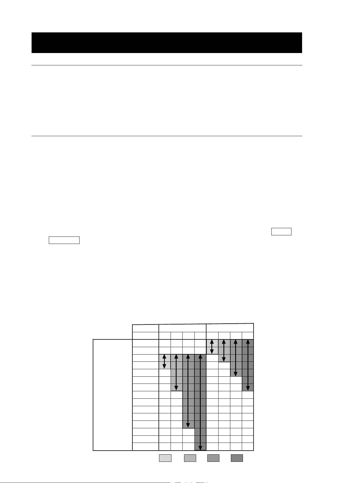
z The table below lists the weight class and recommended measuring range for each model of
the MC series. The measuring range is determined so that the balance repeatability is to be
less than one third of the maximum permissible error for each weight class.
Weight class and recommended measuring range
Weight
(Displayed value)
Model
Class
5 kg
2 kg
1 kg
500 g
200 g
100 g
50 g
20 g
10 g
5 g
2 g
1 g
500 mg
200 mg
100 mg
MC-1000 MC-6100
F1 F2 M1 M2 F1 F2 M1 M2
F1 F2 M1 M2
14
Page 17

When building into a system
z When a special weighing pan is to be designed, the weight of the pan and the material to be
weighed should not exceed the weighing capacity of the balance.
To reduce influences of static electricity and magnetism, use materials other than resin and
magnetic material such as iron.
z There is a function available to maintain the previous weight value in non-volatile memory,
even if the AC adapter is removed.
When “Zero upon power-on
previous weight value is displayed upon power-on.
For details, refer to “Zero upon power-on” on page 33.
z There is a function available to perform span calibration only, when performing calibration with
a tare on the weighing pan.
When “Span calibration
calibration using the internal mass is performed, with a tare on the weighing pan.
For details, refer to “Span calibration” on page 33.
z To set a higher response rate or to batch-weigh small amounts of material, such as a powdery
material, refer to “14. EXTENDED FUNCTION”.
( p-tr )” of “Environment, Display ( ba5fnc )” is set to “ 1 ”, the
( 5pn )” of “Environment, Display ( ba5fnc )” is set to “ 1 ”, span
15
Page 18
6. RESPONSE ADJUSTMENT / SELF CHECK FUNCTION
This function detects the influence on weighing that is caused by drafts and/or vibration at the place
where the balance is installed and sets the response characteristic automatically. When this function
is selected, the balance self-checks the performance at the same time.
Two modes of response adjustment are available: automatic and manual.
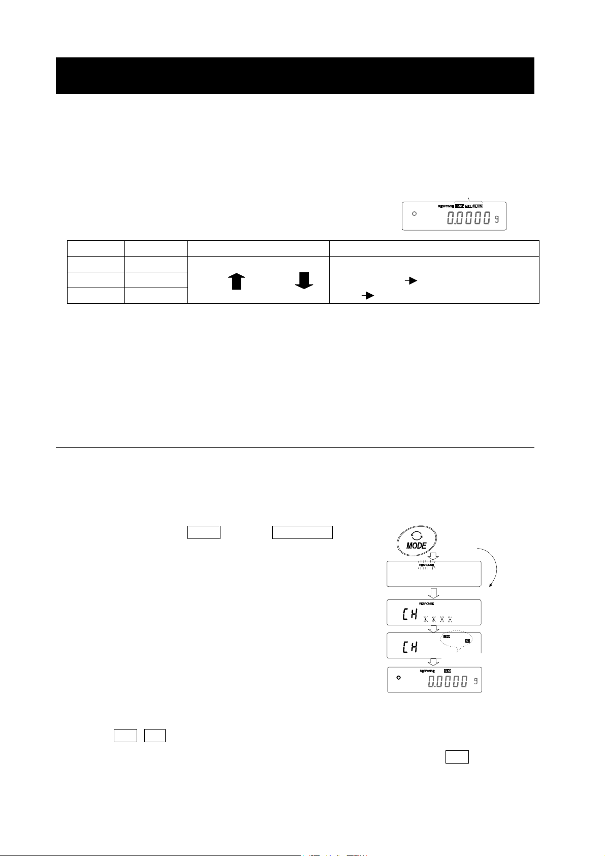
The function has three rates as follows:
Changing the response rate changes the display refresh rate.
Indicator Parameter Response characteristic Display refresh rate
FAST Cond 0
MID. Cond 1
SLOW Cond 2
Note
To set the refresh rate of 5 times/second when the response rate is FAST or 10 times/second
when the response rate is MID. or SLOW, change the “Display refresh rate ( 5pd )” parameter
of “Environment, Display ( ba5fnc )” in the function table. For details, refer to “9. FUNCTION
TABLE”.
Fast response, Sensitive value
Slow response, Stable value
If the response rate is changed as follows:
MID. or SLOW FAST =10 times/second
FAST MID. or SLOW = 5 times/second
Response indicators
6-1 Automatic Response Adjustment / Self Check Function
This function automatically updates the response adjustment by analyzing the influence of the
environment on the weighing data and also self-checks the balance performance using the internal
mass.
Operation
1 Press and hold the MODE key until RESPONSE is
displayed, then release the key.
2 The balance automatically starts to check the balance
performance and sets the response characteristic.
Caution
Do not allow vibration or drafts to affect the balance
during adjustment.
3 After automatic adjustment, the balance displays the
updated response indicator and returns to the
weighing mode. The response indicator remains
displayed for about 30 seconds.
Press and hold
the key
Release the key
Displays the results.
e.g. “ MID. OK ”
The example above indicates that the result of the self check is good and MID. is selected as
the response rate.
16
Page 19
Notes
If improper performance is found in the self check, the
balance displays CH no . Contact the local A&D
dealer for repair.
If the automatic response adjustment fails, the
balance displays CH ng . Check the ambient
conditions such as breeze and vibration, also check
the weighing pan. Then, perform the adjustment again.
To return to the weighing mode, press the CAL key.
If the automatic response adjustment is awkward, try
to refine it using the manual response adjustment.
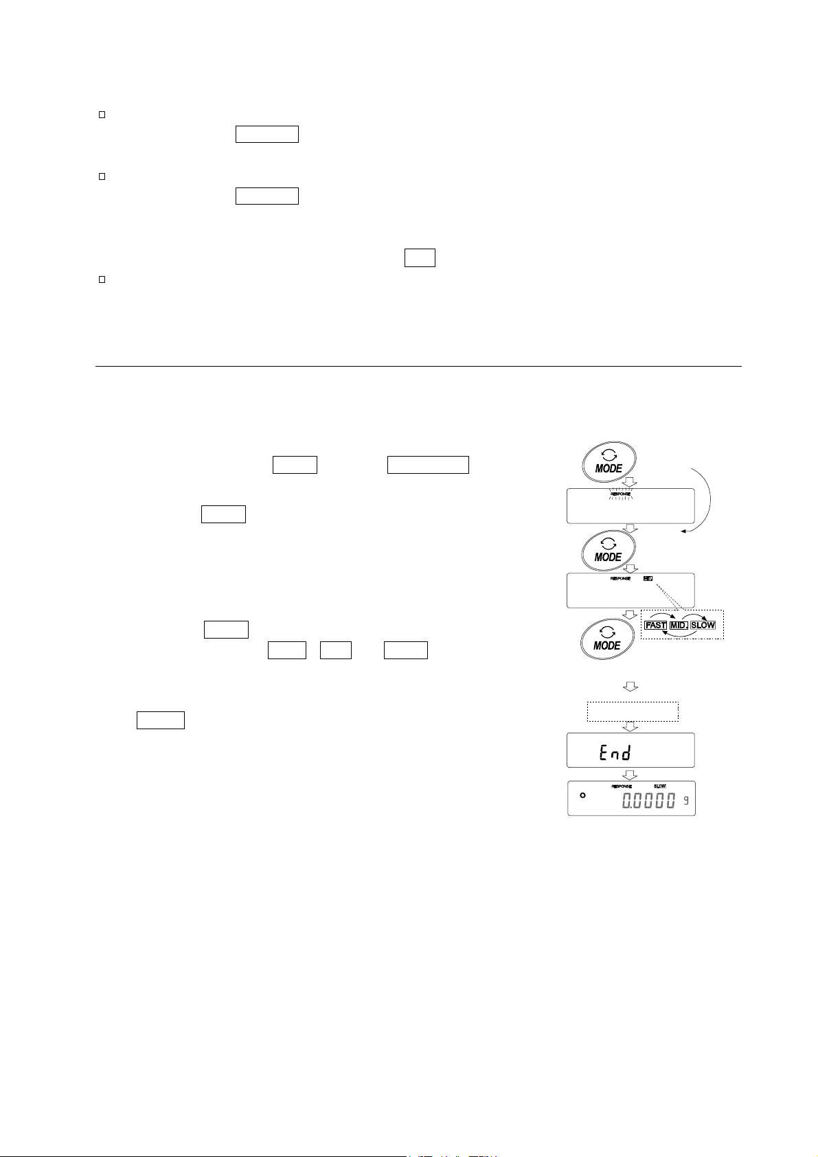
6-2 Manual Response Adjustment
This function manually updates the response adjustment.
Operation
1 Press and hold the MODE key until RESPONSE is
displayed, then release the key.
Press and hold
the key
Press the MODE key again quickly.
2 Press the MODE key to select a rate of the response
adjustment. Either FAST, MID. or SLOW can be
selected.
3 After a few seconds of inactivity the balance displays
eend . Then, it returns to the weighing mode and
displays the updated response indicator. The
response indicator remains displayed for about 30
seconds.
Note
The response adjustment can be changed at “Condition
(Cond)” of “Environment, Display ( ba5fnc )” in the
function table. For details, refer to “9. FUNCTION
TABLE”.
Release the key
and press again
Each pressing
switches
the indicators
After a while
17
Page 20

7. CALIBRATION
7-1 Calibration Group
Calibration z Automatic self calibration (calibration due to changes in temperature)
z Calibration using the internal mass (one-touch calibration)
z Calibration using an external weight
Calibration test z Calibration test using an external weight (Calibration test does not perform
calibration.)
Correction of the internal mass value
Terms
The following terms are defined as follows:
Internal mass = Built-in calibration weight
External weight = A weight that you have. Referred to as a calibration weight when used for calibration.
Calibration weight = A weight used for calibration
Target weight = An external weight used for calibration test
Caution
z Calibration adjusts the balance for accurate weighing.
Besides periodic calibration and before each use, perform calibration when:
• the balance is installed for the first time.
• the balance has been moved.
• the ambient environment has changed.
z Do not allow vibration or drafts to affect the balance during calibration.
z To output the data for GLP using the RS-232C interface, set “GLP output ( info )” of “Data
output ( dout )”. For details, refer to “9. FUNCTION TABLE”. Time and date are added to the
GLP report. If the time or date is not correct, adjust them. For details, refer to the GX series
instruction manual, “10-9 Clock and Calendar Function”.
z Calibration test is available only when “GLP output ( info )” of “Data output ( dout )” is set to
“1 ” or “ 2 ”.
z The calibration and calibration test data can be stored in memory. To store them, set “Data
memory ( data
MEMORY”.
Caution on using an external weight
z The accuracy of an external weight can influence the accuracy of weighing. Select an
appropriate weight as listed below:
Model Usable calibration weight Adjustable range
MC-1000
)” to “ 3 ”. For details, refer to the GX series instruction manual, “12. DATA
1000g, 900g, 800 g, 700 g, 600 g, 500 g, 400 g,
300 g, 200 g
-0.0150 g to +0.0159 g
MC-6100 6000 g, 5000 g, 4000 g, 3000 g, 2000 g -0.150 g to +0.159 g
The calibration weight in bold type: factory setting
The calibration weight value can be adjusted within the range above.
Display
z This indicator means “the balance is measuring calibration data”. Do
not allow vibration or drafts to affect the balance while this indicator is
displayed.
18
Page 21

7-2 Automatic Self Calibration (Calibration due to changes in temperature)
This function automatically calibrates the balance when the balance detects an ambient temperature
change. If GLP output is selected in the function table, the balance outputs the calibration report or stores
the data in memory. Automatic self calibration functions even if the display is turned off (standby state). ,
Caution
If something is on the weighing pan, the balance judges that it is in use and does not perform
automatic self calibration. To maintain the calibrated state, keep the weighing pan clear while
not in use.
The displays shown below are related to the automatic self calibration.
Indicates that the balance detects a change in ambient temperature and
automatic self calibration will start. If the balance is not used for a few
minutes with this indicator blinking, the balance performs automatic self
calibration. The blinking duration depends on the environment.
Indicates that the balance is measuring calibration data. Do not allow
vibration or drafts to affect the balance while this indicator is displayed. After
calibration, the balance returns to indicate the previous display.
Note
The balance can be used while the indicator blinks. But, it is recommended that to maintain
the accuracy, stop using the balance and confirm that there is nothing on the pan and allow
the balance to perform self calibration.
7-3 Calibration Using the Internal mass (One-touch calibration)
This function calibrates the balance using the internal mass. The only operation required is to press
the CAL key
Operation
1 Connect the AC adapter and warm up the balance for at least 30 minutes with nothing on the
weighing pan.
2 Press the CAL key.
3 The balance displays Calin and performs calibration using the internal mass. Do not allow
vibration or drafts to affect the balance.
4 The balance displays end after calibration. If the “GLP output (info )” parameter of the
function table is set to “1 ” or “ 2 ”, the balance displays glp and outputs the “Calibration
Report” using the RS-232C interface or stores the data in memory. For details on the
calibration report format, refer to “10-2 GLP Report”.
5 The balance will automatically return to the weighing mode after calibration.
About the internal mass
The value of the internal mass may change due to corrosion or other damage caused by the
operating environment, or due to aging. Check the internal mass periodically. Correct the internal
mass value as necessary. For details, refer to “7-6 Correcting the Internal Mass Value”.
To maintain the weighing accuracy, perform the calibration using an external weight periodically,
as described below.
19
Page 22

7-4 Calibration Using an External Weight
This function calibrates the balance using an external weight.
When the MC-1000 is used
1 Connect the AC adapter and warm up the balance
for at least 30 minutes with nothing on the pan.
2 Press and hold the CAL key until Calout is
displayed, then release the key.
3 The balance displays Cal 0 .
z If you want to change the calibration weight (a
list of usable weights is shown on page 18),
press the SAMPLE key and proceed to step 4.
z If you use the calibration weight value stored in
the balance, proceed to step 5.
4 Specify the calibration weight value as follows:
SAMPLE key To switch between the
calibration weight selection
mode (All of the digits blinking)
or the value adjustment mode
(The selected digits blinking).
With the MC-1000, the digits in
nd
the 2
places can be adjusted.
With the MC-6100, the digits in
the 2
can be adjusted.
, 3rd, and 4th decimal
nd
and 3rd decimal places
Press and
hold the key
Release
the key
Press
Select a
weight
RE-ZERO key To select the calibration
weight (All of the digits
blinking) or adjust the value
(The selected digits blinking).
Refer to page 18
PRINT key To store the new weight
value. Even if the AC
adapter is removed, the data
is maintained in non-volatile
memory.
CAL key To cancel the operation and
return to 1Cal 0 .
e.g. Calibration
weight value
200.0123 g
To next page
20
Page 23

5 Confirm that there is nothing on the pan and press
the PRINT key. The balance measures the zero
point. Do not allow vibration or drafts to affect the
balance.
The balance displays the calibration weight value.
From previous page
6 Place the displayed calibration weight on the pan
and press the PRINT key. The balance measures
the calibration weight. Do not allow vibration or
drafts to affect the balance.
7 The balance displays end . Remove the weight
from the pan.
8 If the “GLP output (info )” parameter, of the
function table, is set to “1 ” or “ 2 ”, the balance
displays glp and outputs the “Calibration
Report” using the RS-232C interface or stores the
data in memory. For details on the calibration report
format, refer to “10-2 GLP Report”.
9 The balance will automatically return to the
weighing mode.
Calibration
weight
GLP output
10 Place the calibration weight on the pan and confirm
that the value displayed is within ±2 digits of the
specified value. If it is not within the range, check
the ambient conditions such as breeze and
vibration, also check the weighing pan. Then,
repeat steps 1 to 10.
Note
Digit indicates a unit of minimum weighing value.
21
Page 24

7-5 Calibration Test Using an External Weight
This function tests the balance weighing accuracy using an external mass and outputs the result.
This is available only when the “GLP output (info )” parameter is set to “ 1 ” or “ 2 ”. (Calibration test
does not perform calibration.)
When the MC-1000 is used
1 Connect the AC adapter and warm up the balance
for at least 30 minutes with nothing on the pan.
2 Press and hold the CAL key until CCout is
displayed, then release the key.
3 The balance displays CC 0 .
z If you want to change the target weight (a list of
usable weights is shown on page 18), press the
SAMPLE key and proceed to step 4.
z If you use the target weight value stored in the
balance, proceed to step 5.
4 Specify the target weight value as follows:
SAMPLE key To switch between the target
weight selection mode (All of
the digits blinking) or the
value adjustment mode (The
selected digits blinking).
With the MC-1000, the digits in
nd
the 2
places can be adjusted.
With the MC-6100, the digits in
the 2
can be adjusted.
, 3rd, and 4th decimal
nd
and 3rd decimal places
Press
Select a
weight
Press and
hold the key
Release
the key
RE-ZERO key To select the target weight
(All of the digits blinking) or
adjust the value (The
selected digits blinking).
Refer to page 18
PRINT key To store the new weight
value. Even if the AC
adapter is removed, the data
is maintained in non-volatile
memory.
CAL key To cancel the operation and
return to 1CC 0 .
e.g. Target
weight value
200.0123 g
To next page
22
Page 25

5 Confirm that there is nothing on the pan and press the
PRINT key. The balance measures the zero point and
displays the measured value. Do not allow vibration or
drafts to affect the balance.
The balance displays the target weight value.
From previous page
6 Place the displayed target weight on the pan and press
the PRINT key. The balance measures the target weight
and displays the measured value. Do not allow vibration
or drafts to affect the balance.
7 The balance displays end . Remove the weight from the
pan.
8 The balance displays glp and outputs the “Calibration
Test Report” using the RS-232C interface or stores the
calibration test data in memory. For details on the
calibration test report format, refer to “10-2 GLP Report”.
9 The balance will automatically return to the weighing
mode.
Target weight
GLP output
23
Page 26

7-6 Correcting the Internal Mass Value
The MC series balance can correct the internal mass value within the range shown below. This
function corrects the internal mass value to conform to an external weight. The corrected mass value
is maintained in non-volatile memory even if the AC adapter is removed.
The internal mass value is corrected as follows:
Model Correction reference value Correction range
MC-1000 500.0000 g ±0.020 g
MC-6100 2000.000 g ±0.20 g
Example: Using the MC-6100
Use the same weight
4 kg
Correct the internal mass
by +0.030 g in 2 kg.
Calibrate the balance with
the corrected internal mass.
Operation
1 Calibrate the balance using the internal mass (one-touch
calibration). Then, place an external weight and confirm
the value to be corrected.
In the example, the value is off by -0.060 g and the
correction reference value of the MC-6100 is 2 kg. So, the
value is to be corrected by 0.030 g in 2 kg.
2 Press the ON:OFF key to turn off the display.
3 While pressing and holding the PRINT key and the
SAMPLE key, press the ON:OFF key. The balance
displays p5 .
4 kg
With these keys
held down
Press the key
24
Page 27

4 Press the PRINT key. Then the balance displays the
function switches.
Set the function table switch and internal mass correction
switch to “ 1 ” as shown above using the following keys.
SAMPLE key To select the switch to change the value.
RE-ZERO key To change the parameter of the switch
selected.
5 Press the PRINT key to store the new setting. The
balance returns to the weighing mode.
6 Press and hold the SAMPLE key to enter the function
table and release the key when ba5fnc is displayed.
Press and
hold
7 Press the SAMPLE key several times until C5in is
displayed.
8 Press the PRINT key to enter the procedure for correcting
the internal mass value.
9 Correct the internal mass value using the following keys.
RE-ZERO key To select the value.
(-20 digits appear after +20 digits.)
PRINT key To store the new value and display the
next menu of the function table.
CAL key To cancel the correction and display
the next menu of the function table.
10 Press the CAL key. The balance returns to the weighing mode.
11 Press the CAL key to calibrate the balance using the
internal mass.
12 Place the external weight on the pan and confirm that the correction has been performed
properly (Confirm that the value displayed is within the range that is described at “Accuracy
right after calibration using the internal mass” of “17. SPECIFICATIONS”.)
If the internal mass value has not been corrected properly, repeat the procedure, starting at
step 6 and adjust the correction value.
25
Page 28

8. FUNCTION SWITCH AND INITIALIZATION
8-1 Permit or Inhibit
The balance stores parameters that must not be changed carelessly (e.g. Calibration data for
accurate weighing, Data for adapting to the operating environment, Control data for the RS-232C
interface). There are five switches for the purpose of protecting these parameters. Each switch can
select either “permit” or “inhibit”. “Inhibit” protects parameters against careless operations.
Switches
Operation
1 Press the ON:OFF key to turn off the display.
2 While pressing and holding the PRINT key and the SAMPLE key, press the ON:OFF key. The
balance displays p5 .
3 Press the PRINT key. Then the balance displays the function switches.
4 Set the switches using the following keys.
SAMPLE key To select the switch to change the parameter.
RE-ZERO key To change the parameter of the switch selected.
0:To inhibit changes. 1:To permit changes
PRINT key To store the new parameter and return to the weighing mode.
CAL key To cancel the operation. ( Clr is displayed.)
To return to the weighing mode, press CAL key once again.
26
Page 29

8-2 Initializing the Balance
This function returns the following parameters to factory settings.
z Calibration data
z Function table
z The sample unit mass value (counting mode), 100% reference mass value (percent mode)
z The data that is stored in the balance using the data memory function
z External calibration weight and target weight value
z Function switch settings
Note
Be sure to calibrate the balance after initialization.
Operation
1 Press the ON:OFF key to turn off the display.
2 While pressing and holding the PRINT key and the
SAMPLE key, press the ON:OFF key. The balance
displays p5 .
With these keys
held down
Press the key
3 Press the SAMPLE key to display Clr .
4 Press the PRINT key.
To cancel this operation, press the CAL key.
5 Press the RE-ZERO key.
6 Press the PRINT key to initialize the balance.
The balance will automatically return to the weighing
mode.
27
Page 30

9. FUNCTION TABLE
The function table reads or rewrites the parameters that are stored in the balance. These parameters
are stored in non-volatile memory, and are maintained even if the AC adapter is removed.
9-1 Structure and Sequence of the Function Table
The function table menu consists of two layers. The first layer is the “Class” and the second layer is
the “Item”. Each item stores a parameter.
Example
This example sets “Stores weighing data” for “Data memory” and “Every 1 minute” for “Interval time”.
Press and hold
Start, From weighing mode
Class
Press
several
times
Press
several times
Press twice
Item
"Data memory"
Parameter
"Stores weighing
data"
End, To weighing mode
Item
Press
five times
Item
"Interval time"
Parameter
"Every 1 minute"
9-2 Display and Keys
Display/Key Description
The symbol “ ” indicates that the parameter displayed is in effect.
When pressed and held in the weighing mode, enters the function table mode.
Selects the class or item in the function table mode.
Changes the parameter.
When a class is displayed, moves to an item in the class.
When an item is displayed, stores the new parameter and displays the next class.
When an item is displayed, cancels the new parameter and displays the next class.
When a class is displayed, exits the function table mode and returns to the weighing
mode.
28
Page 31

9-3 Details of the Function Table
Class Item and Parameter Description
Fast response rate, sensitive value
MID.
1
Slow response rate, stable value
Stable range is ±1 digit
1
Stable range is ±3 digits
0 OFF
1 Normal
0 5 times/second
0 Point (.)
0 OFF
0 OFF
0 OFF
0 Not used
0 Sets the display to zero.
Does not set the display to zero. Displays the previous value.
With this setting, do not perform re-zero operations frequently.
Refer to “Zero upon power-on” on page 33.
0 Performs zero and span calibration
Performs span calibration only.
Span calibration using the internal mass is possible with a tare
on the weighing pan.
Refer to “Span calibration” on page 33.
No comparison
0
Comparison, excluding “near zero” when stable or overloaded
Comparison, including “near zero” when stable or overloaded
Continuous comparison, excluding “near zero”
Continuous comparison, including “near zero”
Digital input, upper/lower limits
0
Weighing input, upper/lower
limits
ba5fnc
Environment
Display
Cl adj
Clock
Cp fnc
Comparator
Cond
Condition
5t-b
Stability band width
Hold
Hold function
trc
Zero tracking
5pd
Display refresh rate
pnt
Decimal point
p-on
Auto display-ON
poff
Auto display-OFF
g5i
Capacity indicator
f1l
Filter
p-tr
Zero upon power-on
5pn
Span calibration
Cp
Comparator mode
Cp in
Input method
0
2
0
2
1 ON
0 OFF
2 Strong
3 Very strong
1 10 times/second
1 Comma (,)
1 ON
1 ON (10 minutes)
1 ON
1 Used (when the balance is used as a mass comparator)
1
1
Refer to the GX series instruction
manual, “10-9 Clock and Calendar
Function”.
1
2
3
4
1
2 Digital input, reference value
3 Weighing input, reference value
Factory setting
Note: “Digit” is a unit of minimum weighing value
FAST
SLOW
Can be changed by response
adjustment. With “hold 1”,
sets the averaging time.
The stabilization indicator illuminates
when the display fluctuation is
within the range. With “hold 1”,
sets the averaging time.
Holds the display when stable
in animal mode. With “Hold 1”,
ANIMAL turns on.
Keeps zero display by tracking
zero drift.
Period to refresh the display
Decimal point format
Turns on the weighing mode
display when the AC adapter
is plugged in.
Turns off the display after 10
minutes of inactivity.
Capacity indicator
Zero: 0%,
Maximum capacity: 100%
Confirms and sets the time and
date. The time and date are
added to the output data.
Cp Hi, Cp lo can be selected.
Cp ref, Cp lmt can be
selected..
29
Page 32

Class Item and Parameter Description
Cp Hi
Upper limit
Cp lo
Lower limit
Cp ref
Reference value
Cp lmt
To le r anc e
prt
Data output mode
ap-p
Auto print polarity
ap-b
Auto print difference
0
1
2
3
0
1
2
0
1
2
Refer to the GX series
instruction manual, “10-10
Comparator Function”.
Key mode (when stable)
Auto print mode A
(Reference = zero)
Auto print mode B
(Reference = last stable value)
Stream mode /
Interval memory mode
Plus only
Minus only
Both
10 digits
100 digits
1000 digits
Displays when Cp in 0 or
Cp in 1 is selected.
Displays when Cp in 2 or
Cp in 3 is selected.
Accepts the PRINT key only when
the display is stable.
Outputs data when the display is
stable and conditions of ap-p,
ap-b and the reference value are
met.
With data 0, outputs data
continuously; with data 2, uses
interval memory.
Displayed value>Reference
Displayed value<Reference
Regardless of displayed value
Difference between reference
value and displayed value
0 Not used
data
Data memory
1
2
3
dout
Data output
1
2
int
Interval time
3
4
5
6
7
8
d-no
Data number output
5-td
Time/Date output
1
1
2
3
5-id
ID number output
1
pU5e
Data output pause
Note: “Digit” is a unit of minimum weighing value
1
Stores unit mass in counting mode
Stores weighing data
Stores calibration data
0
Every measurement
2 seconds
5 seconds
10 seconds
30 seconds
1 minute
2 minutes
5 minutes
10 minutes
No output
0
Output
No output
0
Time only
Date only
Time and date
No output
0
Output
0
No pause
Pause (1.6 seconds)
Factory setting
Related items:
prt, int, d-no, 5-td, info
Interval time in the interval
memory mode when using prt 3,
data 2
Refer to the GX series
instruction manual, “12. DATA
MEMORY”.
Selects whether or not the time
or date is added to the weighting
data. For details, Refer to the
GX series instruction manual,
"10-9 Clock and Calendar
Function".
Selects whether or not the ID
number is output.
Selects the data output interval.
30
Page 33

Class Item and Parameter Description
at-f
dout
Data output
Auto feed
info
GLP output
ar-d
Zero after output
bp5
Baud rate
btpr
Data bit, parity bit
Crlf
Terminator
5if
Serial
interface
type
Data format
t-Up
Timeout
erCd
AK, Error code
Ct5
CTS, RTS control
Unit
Unit
d5 fnc
Density
function
ld in
Liquid density input
C5 in
Internal mass value correction
id
ID number setting
0
1
0
1
2
0
1
0
1
2
3
4
0
1
2
0
1
0
1
2
3
4
5
0
1
0
1
0
1
g gram
0 Water temperature
1 Liquid density
Not used
Used
No output
AD-8121 format
General data format
Not used
Used
600 bps
1200 bps
2400 bps
4800 bps
9600 bps
7 bits, even
7 bits, odd
8 bits, none
CR LF
CR
A&D standard format
DP format
KF format
MT format
NU format
CSV format
No limit
1 second
No output
Output
Not used
Used
Refer to “7. CALIBRATION”.
Refer to “10. ID NUMBER AND GLP REPORT”.
Factory setting
Selects whether or not automatic
feed is performed.
Selects GLP output method.
For how to set time and date to
be added, refer to the GX series
instruction manual, “10-9 Clock
and Calendar Function”.
Adjusts zero automatically after
data is output.
CR: ASCII code 0Dh
LF: ASCII code 0Ah
Refer to the GX series instruction
manual, "10-6 Description of
Item "Data Format".
Selects the wait time to receive a
command.
AK: ASCII code 06h
Controls CTS and RTS.
Refer to the GX series instruction
manual, "5. WEIGHING UNIT".
Available only when density mode is
selected. Refer to the GX series
instruction manual,
"15. DENSITY MEASUREMENT”.
Displayed only when the internal
mass value correction switch is
set to 1.
31
Page 34

Class Item and Parameter Description
erfnc
Extended
function
Only when
fil is 0
f1-b
Averaging range for
the first moving
average
f1-t
Averaging time for the
first moving average
f2-b
Averaging range for
the second moving
average
f2-t
Averaging time for the
second moving
average
0
1
2
3
5
6
7
0 No averaging
1 0.5 second
3 1.5 seconds
4 2.0 seconds
5 2.5 seconds
6 3.2 seconds
7 4.8 seconds
8 6.4 seconds
0
2
3
4
5
6
0 No averaging
1 0.5 second
2 1.0 second
3 1.5 seconds
4 2.0 seconds
6 3.2 seconds
Small
4
Large
2 1.0 second
Small
1
Large
5 2.5 seconds
Factory setting
Caution
The balance may not transmit the data completely at the specified refresh rate, depending on
the baud rate or data added to the weighing data such as time, date and ID number.
32
Page 35

9-4 Description of the Class “Environment, Display”
Condition ( Cond )
Cond 0 This parameter is for sensitive response to the fluctuation of a weight value.
Used for powder target weighing, weighing a very light sample or when
quick response weighing is required.
After setting, the balance displays FAST.
Cond 2 This parameter is for stable weighing with slow response. Used to prevent a
weight value from drifting due to vibration or drafts.
After setting, the balance displays SLOW.
Notes
In automatic response adjustment, the response rate is selected
automatically.
With “Hold function ( Hold )” set to “ON (1 )”, this item is used to set
the averaging time.
Stability band width ( 5t-b )
This item controls the width to regard a weight value as a stable value. When the fluctuation per
second is less than the parameter, the balance displays the stabilization indicator and outputs or
stores the data. The parameter influences the “Auto print mode”
5t-b 0 This parameter is for sensitive response of the stabilization indicator. Used
for exact weighing.
5t-b 2 This parameter ignores slight fluctuation of a weight value. Used to prevent
a weight value from drifting due to vibration or drafts.
Note
With “Hold function ( Hold )” set to “ON (1 )”, this item is used to set
the stabilization range.
Zero upon power-on ( p-tr )
When a hopper is attached to the weighing pan and loss-in weighing is performed, the remaining
amount of the material will become unknown if tare is performed each time a weighing starts.
When " p-tr " is set to “ 1 ”, tare is not performed at weighing start. So, the remaining amount of the
material can be monitored, when the power is turned on again after it was turned off.
Span calibration ( 5pn )
When a hopper is attached to the weighing pan and calibration is to be performed with the hopper
attached, set " 5pn " to “ 1 ”. When the tare value (hopper and other devices attached) is within the
value in the table below, calibration using the internal mass is possible.
Model Tare value
MC-1000
MC-6100
500 g or less
5 kg or less
33
Page 36

9-5 Description of the Item “Data output mode”
The parameter setting of the “Data output mode ( prt )” applies to the performance when the “Data
memory ( data
transmitted using the RS-232C interface.
Key mode
When the PRINT key is pressed with the stabilization indictor turned on, the balance outputs or
stores the weighing data and the display blinks one time.
Required setting dout prt 0 Key mode
Auto print modes A and B
When the displayed value is stable and the conditions of “Auto print polarity”, “Auto print difference”
and reference value are met, the balance outputs or stores the weighing data.
When the PRINT key is pressed with the stabilization indictor turned on, the balance outputs or
stores the data and the display blinks one time. ,
Mode A: Required setting dout prt 1 Auto print mode A (reference = zero)
dout ap-p Auto print polarity
dout ap-b Auto print difference
)” parameter is set to “ 2 ” (to store the weighing data)and when the data is
Example “For weighing each time a sample is placed and removed.”
Mode B: Required setting dout prt 2 Auto print mode B (reference =
last stable value)
dout ap-p Auto print polarity
dout ap-b Auto print difference
Example “For weighing while a sample is added.”
Stream mode
The balance outputs the weighing data continuously regardless of the display condition. The display
does not blink in this mode. This mode is not available and the interval memory mode is used when
the “Data memory ( data )” parameter is set to “ 2 ” (to store the weighing data).
Required setting dout prt 3 Stream mode
dout data 0 Data memory function is not used.
ba5fnc 5pd Display refresh rate
5if bp5 Baud rate
Example “For monitoring data on a computer”
Caution
The balance may not transmit the data completely at the specified refresh rate, depending
on the baud rate or data added to the weighing data such as time, date and ID number.
34
Page 37

Interval memory mode
The weighing data is periodically stored in memory.
Required setting dout prt 3 Interval memory mode
dout data 2 Data memory function is used.
Stores weighing data.
dout int Interval time
Optional setting dout 5-td1, 2, or 3
Example “For periodical weighing without a computer command and
outputting all of the data to a computer at one time”
Adds the time and date.
9-6 Description of the Item “Data format”
A&D standard format 5if type 0
This format is used when the peripheral equipment can receive the A&D format. If an AD-8121B is
used, set the printer to MODE 1 or 2.
z This format consists of fifteen or sixteen characters excluding the terminator.
With the MC-1000, when the numerical data excluding the decimal point exceeds eight
characters, the data format will be sixteen characters long.
z A header of two characters indicates the balance condition.
z The polarity sign is placed before the data with the leading zeros. If the data is zero, the plus sign is used.
z The unit, consisting of three characters, follows the data.
C
ST,+000.012788g
UnitDataHeader
ST,+1000.000088g
UnitDataHeader
L
R
F
Termina t o r
C
L
R
F
Termin a t o r
(Data example exceeding 8 characters)
DP (Dump print) format 5if type 1
This format is used when the peripheral equipment can not receive the A&D format. If an AD-8121B
is used, set the printer to MODE 3.
z This format consists of sixteen characters excluding the terminator.
z A header of two characters indicates the balance condition. No overload header is used.
z The polarity sign is placed before the data, with spaces in place of leading zeros, if the data is
not zero or overloaded.
z The unit, consisting of three characters, follows the data.
WT +1000.0000
Header Data
Unit
CRL
F
Terminator
35
Page 38

KF format 5if type 2
This is the Karl-Fischer moisture meter format and is used when the peripheral equipment can only
communicate using this format.
z This format consists of fourteen characters excluding the terminator.
z This format has no header characters.
z The polarity sign is placed before the data, with spaces in place of leading zeros, if the data is
not zero or overloaded.
z This format outputs the unit only for a stable value.
+1000.0000 g
Data
Unit
g
CRL
F
Termin a t o r
Stable value
Unstable value
MT format 5if type 3
z A header of two characters indicates the balance condition.
z The polarity sign is used only for negative data.
z The weighing data uses spaces in place of the leading zeros.
z The character length of this format changes dependent upon the unit
S 1000.0000 g
Header
Unit
CRL
Termin a t o rData
F
NU (Numerical) format 5if type 4
This format outputs only numerical data.
z This format consists of nine or ten characters excluding the terminator.
With the MC-1000, when the numerical data excluding the decimal point exceeds eight
characters, the data format will be ten characters long.
z The polarity sign is placed before the data with the leading zeros. If the data is zero, the plus
sign is used.
+000.0127
Data
+1000.0000
Data
CRL
F
Ter mi nato r
CRL
F
Ter mi nator
(Data example exceeding 8 characters)
36
Page 39

CSV format 5if type 5
z Separates the data of A&D standard format and the unit by a comma (,).
z Outputs the unit even when the data is overloaded.
z When the ID number, data number, time and date are added, outputs the ID number, data
number, date, time and weighing data in this order and separates each item by a comma and
treats all the items as one group of data.
Note
To add the ID number, data number, time and date, the function settings must be changed.
LAB-123, No,012, 2009/12/31, 12:34:56, ST,+1000.0000, g<CR><LF>
ID number Data number Date Time Weighing data
ST,+1000.0000, g
OL,+
9999999E+1
9, g
CRL
F
CRL
F
9-7 Description of the Data Format Added to the Weighing Data
ID number dout 5-id 1
The number to identify a specific balance.
z This format consists of seven characters excluding the terminator.
Data number dout d-no 1
This format outputs the data number just before the data is transmitted using the RS-232C interface.
z This format consists of six characters excluding the terminator.
z When CSV format ( 5if type 5 ) is selected, the period (
Note
The data number is added only to the weighing data that is stored in memory.
. ) is replaced with a comma ( , ).
Date dout 5-td 2 or 3
z The date output order can be changed in “Clock ( Cl adj )”. Outputs the year in four-digit
format.
2009/12/31
CRL
F
Time dout 5-td 1 or 3
z Outputs time in 24-hour format.
Note
When the data described above is added to the weighing data, the output is in the following
order: ID number, Data number, Date, Time and Weighing data.
37
Page 40

9-8 Data Format Examples
Stable
(Data example
exceeding 8 characters)
A&D
DP
KF
MT
NU
A&D
NU
ST, + 00001. 72
WT
+
S
+
00 001. 72
ST, + 00100 . 00
+10 000
1
+
1
00
72
.
1. 72g
.
0
.
00
CRL
72
g
00
F
CRL
00
0
F
g
C
R
CRL
C
L
R
F
CRL
g
L
F
F
g
F
C
L
R
F
Unstable
(Data example
exceeding 8 characters)
Overload
Positive error
Overload
Negative error
A&D
DP
KF
MT
NU
A&D
NU
A&D
DP
KF
MT
NU
A&D
DP
KF
MT
NU
CRL
CRL
CRL
C
R
CRL
F
F
g
CRL
F
CRL
L
F
F
CRL
F
CRL
F
L
FCR
F
F
L
FCR
US, - 00183. 96g
US
-
183
D
S
-0018 3 . 96
US
-1210 0 00
OL , + 9 99 9 9 9 E 1
SI+
+999 9 9999
OL , - 9 9 9 9 9 9 E 1+99
SI -
-99999999
-183 . 96g
.
96
00
-
,-
CRL
CRL
183
.
H
F
L
F
96
.
C
0
.
7
E
CRL
-
E
CRL
R
00
L
F
12100 0
CRL
F
F
00
7
F
+99
Unit
g (gram) g
A&D
D.P.
KF MT
g
g
g
Space, ASCII 20h
C
Carriage Return, ASCII 0Dh
R
L
Line Feed, ASCII 0Ah
F
38
Page 41

10. ID NUMBER AND GLP REPORT
z The ID number is used to identify the balance when Good Laboratory Practice (GLP) is used.
z The ID number is maintained in non-volatile memory even if the AC adapter is removed.
z The GLP output format is selected at “GLP output (info )” of the function table and can be
output to a personal computer or printer using the RS-232C serial interface.
z The GLP output format includes the balance manufacturer, model, serial number, ID number,
date, time and space for signature for weighing data, and the weight used and results for
calibration or calibration test data.
z The balance can output the following reports for GLP.
“Calibration report” of the calibration, using the internal mass (Calibration due to changes in
temperature and one-touch calibration.)
“Calibration report” of the calibration, using an external weight.
“Calibration test report” of the calibration test, using an external weight.
“Title block” and “End block” for the weighing data.
z Calibration and calibration test data can be stored in memory to output several reports at the
same time. Refer to the GX series instruction manual, “12. DATA MEMORY” for details.
z For details on confirming and setting the time and date, refer to the GX series instruction
manual, “10-9 Clock and Calendar Function”.
10-1 Setting the ID Number
1 Press and hold the SAMPLE key until ba5fnc of the function table is displayed.
2 Press the SAMPLE key several times to display id .
3 Press the PRINT key. Set the ID number using the following keys.
RE-ZERO key To set the character of the digit selected. Refer to the display character
set shown below.
SAMPLE key To select the digit to change the value.
PRINT key To store the new ID number and display ba5fnc .
CAL key To cancel the new ID number and display ba5fnc .
4 With ba5fnc displayed, press the CAL key to return to the weighing mode.
Display character set
0123456789
ABCDEFGH
-
Space
39
I
JKLM
NOPQRSTUVWXYZ
Page 42

10-2 GLP Report
Set the following parameters to output the report.
z To print the report, set the “GLP output ( info )” parameter to “1 ”, the “Data output pause
( pU5e )” parameter to “1 ”, and use MODE 3 of the AD-8121B. For details on using the printer,
refer to “12-1 Connection to the AD-8121B Printer”.
z To output the report to a personal computer using the RS-232C interface, set the “GLP output
( info )” parameter to “ 2 ”.
z If the time and date are not correct, set the correct time and date in “Clock ( Cl adj )” of the
function table.
Calibration report using the internal mass
When the setting is “info 1 ”: When the setting is “info 2 ”:
AD-8121 format
A & D
MODEL MC-1000
S/N 01234567
ID ABCDEFG
DATE 2009/12/31
TIME 12:34:56
CALIBRATED(INT.)
SIGNATURE
- - - - - - - -
<TERM>
Space, ASCII 20h
Terminator, , or
C
R
Carriage return, ASCII 0Dh
L
F
Line feed, ASCII 0Ah
General data format
Manufacturer
Model
Serial number
ID number
Date
Time
Calibration type
Signature
~~~~~~~~~~~A~&~
MODEL
S/N
~~~~~
ID
~~~~~~~
MC-1000<TERM>
~~~~
01234567<TERM>
ABCDEFG<TERM>
DATE<TERM>
~~~~~~
2009/12/31<TERM>
TIME<TERM>
~~~~~~~~
12:34:56<TERM>
CALIBRATED(INT.)<TERM>
SIGNATURE<TERM>
<TERM>
<TERM>
----------------<TERM>
<TERM>
<TERM>
C
R
C
L
F
R
D<TERM>
40
Page 43

Calibration report using an external weight
When the setting is “info 1 ”: When the setting is “info 2 ”:
AD-8121 format General data format
A & D
MODEL MC-1000
S/N 01234567
ID ABCDEFG
DATE 2009/12/31
TIME 12:34:56
CALIBRATED(EXT.)
CAL.WEIGHT
+2000.0000g
SIGNATURE
- - - - - - - -
<TERM>
C
L
F
R
Space, ASCII 20h
Terminator, , or
C
R
Carriage return, ASCII 0Dh
Line feed, ASCII 0Ah
Manufacturer
Model
Serial number
ID number
Date
Time
Calibration type
Calibration
weight
Signature
C
L
F
R
~~~~~~~~~~~A~&~
MODEL
S/N
~~~~~
ID
~~~~~~~
MC-1000<TERM>
~~~~
01234567<TERM>
ABCDEFG<TERM>
D<TERM>
DATE<TERM>
2009/12/31<TERM>
TIME<TERM>
~~~~~~~~
12:34:56<TERM>
CALIBRATED(EXT.)<TERM>
CAL.WEIGHT<TERM>
~~~~~
+2000.0000g<TERM>
SIGNATURE<TERM>
<TERM>
<TERM>
----------------<TERM>
<TERM>
<TERM>
Calibration test report using an external weight
(Calibration test does not perform calibration.)
When the setting is “info 1 ”: When the setting is “info 2 ”:
AD-8121 format
A & D
MODEL MC-1000
S/N 01234567
ID ABCDEFG
DATE 2009/12/31
TIME 12:34:56
CAL.TEST(EXT.)
ACTUAL
0.0000g
+1999.9999g
TARGET
+2000.0000g
SIGNATURE
- - - - - - - -
<TERM>
Space, ASCII 20h
Terminator, , or
C
R
Carriage return, ASCII 0Dh
L
F
Line feed, ASCII 0Ah
Manufacturer
Model
Serial number
ID number
Date
Time
Calibration test
type
Zero point value
Tar g e t w e i gh t
value
Tar g e t w e i gh t
Signature
C
R
C
L
R
F
General data format
~~~~~~~~~~~A~&~
MODEL
S/N
~~~~~
ID
~~~~~~~
MC-1000<TERM>
~~~~
01234567<TERM>
ABCDEFG<TERM>
DATE<TERM>
~~~~~~
2009/12/31<TERM>
TIME<TERM>
~~~~~~~~
12:34:56<TERM>
CAL.TEST(EXT.)<TERM>
ACTUAL<T E R M >
~~~~~~~~~
~~~~~
0.0000g<TERM>
+1999.9999g<TERM>
TARGET<T E R M >
~~~~~
+2000.0000g<TERM>
SIGNATURE<TERM>
<TERM>
<TERM>
----------------<TERM>
<TERM>
<TERM>
D<TERM>
41
Page 44

Title block and end block
When a weight value is recorded as the GLP data, “Title block” and “End block” are inserted at the
beginning and at the end of a group of weight values, in the GLP report.
Notes
To output the report to an AD-8121B , use MODE 3 of the AD-8121B.
If the data memory function is used, the “Title block” and “End block” can not be output.
Operation
1 With the weighing data displayed, press and hold the PRINT key until S5tart is displayed.
The “Title block” is output.
2 The weighing data is output according to the parameter setting of the data output mode.
3 Press and hold the PRINT key until recend is displayed. The “End block” is output.
When the setting is “info 1 ”: When the setting is “info 2 ”:
AD-8121 format
A & D
MODEL MC-1000
S/N 01234567
ID ABCDEFG
DATE 2009/12/31
START
TIME 09:30:00
WT +1234.5600g
WT +1234.6100g
WT +1234.6200g
WT +1234.6300g
WT +1234.5100g
WT +1234.5300g
WT +1234.7100g
WT +1234.6400g
END
TIME 10:40:15
SIGNATURE
- - - - - - - -
<TERM>
Space, ASCII 20h
Terminator, , or
C
R
Carriage return, ASCII 0Dh
L
F
Line feed, ASCII 0Ah
Title block
Manufacturer
Model
Serial number
ID number
Date
Time
General data format
~~~~~~~~~~~A~&~
MODEL
S/N
~~~~~
ID
~~~~~~~
DATE<TERM>
~~~~~~
START<TERM>
MC-1000<TERM>
~~~~
01234567<TERM>
ABCDEFG<TERM>
2009/12/31<TERM>
D<TERM>
TIME<TERM>
~~~~~~~~
09:30:00<TERM>
<TERM>
Weighing data
WT
WT
WT
WT
WT
WT
WT
WT
+1234.5600g<TERM>
~~~
+1234.6100g<TERM>
~~~
+1234.6200g<TERM>
~~~
+1234.6300g<TERM>
~~~
+1234.5100g<TERM>
~~~
+1234.5300g<TERM>
~~~
+1234.7100g<TERM>
~~~
+1234.6400g<TERM>
~~~
<TERM>
Time
Signature
END<TERM>
TIME<TERM>
~~~~~~~~
10:40:15<TERM>
SIGNATURE<TERM>
<TERM>
<TERM>
----------------<TERM>
End block
<TERM>
<TERM>
C
R
C
L
F
R
42
Page 45

11. RS-232C SERIAL INTERFACE / EXTERNAL INPUT
RS-232C
The balance is a DCE device. Connect the balance to a personal computer (DTE), using a straight
through cable or a modem cable.
Transmission system : EIA RS-232C
Transmission form : Asynchronous, bi-directional, half duplex
Data format : Baud rate : 600, 1200, 2400, 4800, 9600 bps
Data bits : 7 or 8 bits
Parity : Even, Odd (Data bits 7 bits)
None (Data bits 8 bits)
Stop bit : 1 bit
Code : ASCII
Pin connections
Pin No. Signal
name
1 FG - Frame ground
2 RXD Input Receive data
3 TXD Output Transmit data
4 RTS Input Ready to send
5 CTS Output Clear to send
6 DSR Output Data set ready
7 SG - Signal ground
18 PRINT Input Same as the PRINT key
19 RE-ZERO Input Same as the RE-ZERO key
8 – 25 (Excluding 18 and 19) - - Not connected
Note
The signal names for the RS-232C are the same as those for the DTE side except TXD and
RXD.
Direction Description
Circuits
43
Page 46

RS-232C Terminals
Balance side
DCE
Computer side
DTE
Inside of balance
Terminals sample
External contact input
By connecting pin 18 (PRINT command) to pin 7, or pin 19 (RE-ZERO command) to pin 7 for 100 ms
or more, the same operation as performed by pressing the PRINT key or the RE-ZERO key, will be
performed.
Example of foot switch
Connector
AX-HDB-25P
Connector cover
AX-HDB-CTF
Foot switch
AX-SW128
Option
Connector : AX-HDB-25P/CTF
Foot switch : AX-SW128
Balance side
44
PRINT
key
RE-ZERO
key
Page 47

12. CONNECTION TO PERIPHERAL EQUIPMENT
12-1 Connection to the AD-8121B Printer
Set the following parameters to use the AD-8121B printer.
AD-8121B
3
Not
applicable
0, 1, 2, 4, 5
*1
0, 1
0,1, 2, 3
0,1
0,1 *2
0,1
Factory
setting
0
0
1
0 0 0
0 0 0
0 0 0
0 0 0
0 0 0
2 2 2 2
0 0 0 0
0 0 0 0
0 0 0 1
0 0 0 0
Mode 1 Mode 2 Mode 3
0, 1, 2, 4, 5
**1
Class Item
prt
Data output mode
ap-p
Auto print polarity
ap-b
Auto print difference
d-no
dout
Data output
5if
Serial
interface
*1 Set the parameter when the data output mode is set to the auto print mode ( prt 1 or prt 2 ).
*2 When multiple lines are to be printed, set the parameter to 1.
Data number output
5-td
Time/date output
5-id
ID number output
pU5e
Data output pause
at-f
Auto feed
bp5
Baud rate
ptpr
Data bit, parity bit
Crlf
Terminator
type
Data format
Ct5
CTS, RTS control
AD-8121B settings
Mode AD-8121B DIP switches Description
Mode 1
Mode 2
Mode 3
DIP switch 3: Handling unstable data DIP switch 4: Data input specification
ON = To print unstable data ON = Use the current loop
OFF = Not to print unstable data OFF = Use the RS-232C
With data 0, the weight data can be output to the printer.
With data 2, the weight data stored in memory can be output to the printer.
With data 3, the calibration report stored in memory can be output to the printer.
Refer to “10. ID NUMBER AND GLP REPORT” for print samples.
Prints upon data receipt
Standard mode, statistical calculation mode
Prints using the AD-8121B DATA key or the AD-8121B
built-in timer
Standard mode, interval mode, chart mode
Prints upon data receipt
Dump print mode
45
Page 48

12-2 Connection to a Computer
The MC series balance is of the DCE type (Data Communication Equipment), which can be
connected to a personal computer using the RS-232C interface.
Before connection, read the personal computer manual thoroughly.
Use a standard DCE cable for connection (cable type: straight-through).
12-3 Using Windows Communication Tools (WinCT)
When Windows is used as an operating system in a personal computer, the provided WinCT can be
used to transmit the weighing data to the personal computer.
The WinCT has two communication methods: “RsCom” and “RsKey”. For details on WinCT, refer to
the WinCT instruction manual.
The current version of the WinCT can be downloaded from the A&D website.
RsCom
z Can transmit commands to control the balance.
z Can perform bi-directional communication between the balance and a personal computer
using the RS-232C interface.
Can display or store the data using a text file format. Can also print the data using a printer
z
connected to the personal computer.
z When several ports of a personal computer have balances connected, the personal computer
can communicate with each balance simultaneously.
z Can share a personal computer with other application software.
z Can receive the balance GLP report.
RsKey
z Can transmit the weighing data output from the balance directly to other application software
such as Microsoft Excel.
z Can be used with most application software.
z Can receive the balance GLP report.
Note
Windows and Excel are the registered trademarks of the Microsoft Corporation.
Using the WinCT software, the balance can do the following:
1 Analyzing the weighing data and the statistics input by “RsKey”
The weighing data can be input directly into an Excel worksheet. Then, Excel can analyze the
data to obtain total, average, standard deviation, maximum and minimum value, and display
them in a graph.
2 Controlling the balance using commands from a personal computer
By using “RsCom”, the personal computer sends commands such as “re-zero” or “send
weighing data” to the balance and controls the balance.
46
Page 49

3 Printing the balance GLP report using your printer
The balance GLP report can be printed using a printer connected to the personal computer.
4 Receiving weighing data at a certain interval
The weighing data can be received at a certain interval and data characteristic with elapsed
time can be obtained.
5 Using the MC series balance memory function
The weighing data, instead of outputting it immediately to an external device, can be stored in
the balance’s memory. Later, all of the weighing data stored can be output to a personal
computer at one time.
6 Using a personal computer as an external indicator
With the “RsKey” test mode function, a personal computer can be used as an external weight
indicator for the balance. (To do this, set the balance data output mode to stream mode.)
47
Page 50

13. COMMANDS
13-1 Command List
Commands to query weighing data
C Cancels the S or SIR command.
Q Requests the weighing data immediately.
S Requests the weighing data when stabilized.
SI Requests the weighing data immediately.
SIR Requests the weighing data continuously.
E
S
P Requests the weighing data when stabilized.
C
Note: The “Q” and “SI” commands, the “S” and “
Commands to control the balance
CAL Same as the CAL key.
OFF Turns the display off.
ON Turns the display on.
P Same as the ON:OFF key
PRT Same as the PRINT key
R Same as the RE-ZERO key
SMP Same as the SAMPLE key.
T Same as the RE-ZERO key
Z Same as the RE-ZERO key
E
S
T Same as the RE-ZERO key
C
U Same as the MODE key
UN:mm Changes the unit mass stored in memory with the number of mm (01-20).
?UN Outputs the unit mass number of the selected unit mass.
UW:∗∗∗. ∗∗ g Sets the unit mass value. e.g.,UW:+0.123 g (to set the unit mass to
0.123 g: represents a space.)
?UW Outputs the unit mass value of the selected unit mass number.
?ID Requests the ID number.
?SN Requests the serial number.
?TN Requests the model name.
E
Note: The “R”, “T”, “Z” and “
S
T” commands behave the same.
C
E
S
P” commands behave the same.
C
Commands to control the comparator function
HI:∗∗∗. ∗∗ g Sets the upper limit value. e.g.,HI:+2.34 g (to set the upper limit
value to 2.34 g: represents a space.)
LO:∗∗∗. ∗∗ g Sets the lower limit value. e.g.,LO:+1.23 g (to set the lower limit
value to 1.23 g: represents a space.)
?HI Outputs the upper limit value.
?LO Outputs the lower limit value.
Note: To use a command to control the comparator function, set the “Input method
( Cpin )” parameter to “ 0 ” or “ 1 ”.
Commands to control the memory function
MCL Deletes all data in memory.
MD:nnn Deletes weighing data with the data number nnn.
?MA Outputs all data in memory.
?MQnnn Outputs weighing data with the data number nnn.
?MX Outputs the number of weighing data in memory.
Note: “nnn” indicates a three-digit numerical value.
E
S
: 1Bh in ASCII code
C
48
Page 51

13-2 Acknowledge Code and Error Codes
When the “Serial interface function ( 5if )” parameter is set to “ erCd 1 ”, the balance outputs <AK>
code or error code to each command as follows:
<AK> (06h) Acknowledge in ASCII code.
z When the balance receives a command to request data and can not process it, the balance
transmits an error code (EC, Exx).
When the balance receives a command to request data and can process it, the balance
outputs the data.
z When the balance receives a command to control the balance and can not process it, the
balance transmits an error code (EC, Exx).
When the balance receives a command to control the balance and can process it, the balance
transmits the acknowledge code.
Among commands to control the balance, the following transmit the acknowledge code both
when the balance receives the command and when the balance has accomplished the
command. If the command can not be processed properly, the balance transmits an error code
(EC, Exx). This error can be released using the CAL command.
CAL command (Calibration command) ON command (Display ON command)
P command (Display ON/OFF command) R command (RE-ZERO command)
R command
Personal computer Time Balance
R command
CRL
R
F
C
L
AK
R
F
CRL
AK
F
Weighing mode
Command received
In process
Command completed
Zero display
z When a communication error has occurred due to external noise, or a parity error has
occurred due to transmission error, the balance transmits an error code. In this case, send the
command again.
49
Page 52

13-3 Control Using CTS and RTS
Depending on the “ Ct5 ” parameter of “Serial interface ( 5if )”, the balance performs as follows:
Ct5 0
Regardless of whether the balance can receive a command or not, the balance keeps the CTS line
HI. The balance outputs data regardless of condition of the RTS line.
Ct5 1
The CTS line is kept Hi normally. When the balance can not receive the next command (e.g. while
the balance is processing last command), the balance sets the CTS line to Lo. The balance confirms
the level of the RTS line before outputting a set of data. If the RTS level is Hi, the balance outputs
data. If the RTS level is Lo, data is not output (The data is canceled).
13-4 Settings Related to RS-232C
Concerning the RS-232C, the balance has two functions: “Data output ( dout )” and “Serial interface
( 5if )”. Set each function as necessary.
50
Page 53

14. EXTENDED FUNCTION
The MC series balance has several extended functions equipped for special applications or to
troubleshoot when using the standard functions.
When the "Filter ( f1l)” is set to “ 0 “, extra items are available as shown below.
Class Item and Parameter Description
erfnc
Extended
function
f1-b
Averaging range for
the first moving
average
f1-t
Averaging time for the
first moving average
f2-b
Averaging range for
the second moving
average
f2-t
Averaging time for the
second moving
average
0
1
2
3
5
6
7
0 No averaging
1 0.5 second
3 1.5 seconds
4 2.0 seconds
5 2.5 seconds
6 3.2 seconds
7 4.8 seconds
8 6.6 seconds
0
2
3
4
5
6
0 No averaging
1 0.5 second
2 1 second
3 1.5 seconds
4 2.0 seconds
6 3.2 seconds
Small
4
Large
2 1 second
Small
1
Large
5 2.5 seconds
When the fluctuation of a weight value is
within the averaging range, the averaging
operation starts to stabilize the value.
When the fluctuation is small, for example,
when weighing or filling a small amount of
sample, the averaging operation is always
performed and the response rate may be
slow. Under such a condition, change the
parameter.
Refer to “Averaging range ( f1-b ) and
averaging time ( f1-t )”
When the fluctuation of a weight value is
within the averaging range, the averaging
operation starts. Once the duration of
averaging operations reaches the averaging
time, moving averaging starts.
This parameter sets the time to start moving
averaging.
Refer to “Averaging range ( f1-b ) and
averaging time ( f1-t )”
Refer to “Filter depending on differences in
the amount to deliver powdery and liquid
material”.
51
Page 54

14-1 Description of "Averaging range" and "Averaging time"
Averaging range ( f1-b ) and averaging time ( f1-t )
1. When the fluctuation of a weight value is beyond the range that is selected in " f1-b ", the
averaging operation is disabled and the display reflects the varying value.
2. Once the fluctuation becomes within the selected range, the averaging operation starts to
stabilize the weight value.
3. The process of averaging increases. When the selected time is reached, moving averaging
will be performed.
When a small amount of sample is weighed or is filled, the fluctuation of a weight value is too
small to be beyond the selected range and the averaging operation is not disabled. Consequently
moving averaging is always performed and it takes a longer time to reach the final weight value.
Under such a situation, change the setting of " f1-b " to a smaller range. But please note that the
smaller the range is, the more prone to external disturbance the value will become.
52
Page 55

Filter depending on differences in the amount to deliver powdery and liquid
material
z When the weight value is not stable even without load fluctuations
Increase the averaging range for the first moving average parameter ( f1-b ).
Increase the averaging time for the first moving average parameter ( f1-t ).
Strengthen the digital filter. (Increase the function setting “Condition ( Cond )” parameter.)
z When response is slow during full and medium flow
Decrease the averaging range for the first moving average parameter ( f1-b ).
Weaken the digital filter. (Decrease the function setting “Condition ( Cond )” parameter.)
z When response is slow during dribble flow
Decrease the averaging time for the first moving average parameter (f1-t).
Weaken the digital filter. (Decrease the function setting “Condition ( Cond )” parameter.
z To increase stability without load fluctuations
Increase the averaging range for the second moving average parameter ( f2-b ).
Increase the averaging time for the second moving average parameter ( f2-t ).
53
Page 56

15. MAINTENANCE
z Do not use organic solvents to clean the balance. Clean the balance with a lint free cloth that
is moistened with warm water and a mild detergent.
z Do not disassemble the balance. Contact the local A&D dealer if the balance needs service or repair.
z Use the original packing material for transportation.
16. TROUBLESHOOTING
16-1 Checking the Balance Performance and Environment
The balance is a precision instrument. When the operating environment or the operating method is
inadequate, correct weighing can not be performed. Place a sample on the pan and remove it, and
repeat this several times. If the balance seems to have a problem with repeatability or to perform
improperly, check as described below. If improper performance persists after checking, contact the
local A&D dealer for repair.
Checking that the balance performs properly
z Check the balance performance using the self-check function as described in “6-1 Automatic
Response Adjustment / Self Check Function”.
An error display appears when a malfunction is found.
z Check the balance repeatability using an external weight. Be sure to place the weight in the
center of the weighing pan.
z Check the balance repeatability, linearity and calibrated value using external weights with a
known value.
Checking that the operating environment or weighing method is proper
Operating environment
z Is the weighing table solid enough (especially for the balance with a minimum weighing value
of 0.0001 g)?
z Is the balance level? Refer to “3-1 Before Use”.
z Is the operating environment free from vibration and drafts? Has the breeze break been installed?
z Is there a strong electrical or magnetic noise source such as a motor near the balance?
Weighing method
z Does the weighing pan touch the breeze ring or anything? Is the weighing pan installed
correctly?
z Is the RE-ZERO key pressed before placing a sample on the weighing pan?
z Is the sample placed in the center of the weighing pan?
z Has the balance been calibrated using the internal mass (one-touch calibration)?
z Has the balance been warmed up for 30 minutes before weighing?
54
Page 57

Sample and container
z Has the sample absorbed or lost moisture due to the ambient conditions such as temperature
and humidity?
z Has the temperature of the container been allowed to equalize to the ambient temperature?
Refer to “3-2 During Use”.
z Is the sample charged with static electricity? Refer to “3-2 During Use”.
Static electricity is generated when the relative humidity is low.
z Is the sample of magnetic material such as iron? Caution is required for weighing magnetic
materials. Refer to “3-2 During Use”.
16-2 Error Codes
Display Error code Description
EC, E11 Stability error
The balance can not stabilize due to an environmental
problem. Prevent vibration, drafts, temperature
changes, static electricity and magnetic fields.
Refer to “3. PRECAUTIONS” for details on the
operating environment and “6. RESPONSE
ADJUSTMENT” about adapting the balance to the
environment.
To return to the weighing mode, press the CAL key.
EC, E16 Internal mass error
Applying the internal mass does not yield a change in
the weighing value as specified.
Confirm that there is nothing on the pan and perform
the weighing operation from the beginning again.
EC, E17 Internal mass error
The internal mass application mechanism does not
function properly.
Perform the weighing operation from the beginning
again.
EC, E20 Calibration weight error
The calibration weight is too heavy. Confirm the
calibration weight value.
Press the CAL key to return to the weighing mode.
EC, E21 Calibration weight error
The calibration weight is too light. Confirm the
calibration weight value.
Press the CAL key to return to the weighing mode.
55
Page 58

Display Error code Description
Overload error
A sample beyond the balance weighing capacity has
been placed on the pan.
Remove the sample from the pan.
Weighing pan Error
The weight value is too light.
Confirm that the weighing pan is properly installed and
calibrate the balance.
Sample mass error
The balance can not store the sample for the counting
mode or for the percent mode because it is too light.
Use a larger sample.
Unit mass error
The sample unit mass for the counting mode is too
light. Storing and using it for counting will cause a
counting error.
Add samples to reach the specified number and press
the PRINT key.
Pressing the PRINT key without adding samples will
shift the balance to the counting mode. But, for
accurate counting, be sure to add samples.
Automatic response adjustment zero error
The automatic response adjustment can not be
performed because there is something on the pan.
Clear the pan. Press the CAL key to return to the
weighing mode.
(CHECK NG)
(CHECK NO)
Automatic response adjustment unstable error
The automatic response adjustment can not be
performed because the weight value is unstable.
Check the ambient conditions such as breeze,
vibration and magnetic fields, also check the weighing
pan. Press the CAL key to return to the weighing mode.
Internal error
Indicates an internal error as the result of the self-check
function.
Repair is required. Contact the local A&D dealer.
Clock battery error
The clock backup battery has been depleted.
Press any key and set the time and date. The clock and
calendar function works normally as long as the AC
adapter is connected to the balance. If this error appears
frequently, contact the local A&D dealer.
56
Page 59

Display Error code Description
(Blinking)
(Illuminated)
Memory type error
EC, E00 Communications error
Memory full
The amount of weighing data in memory has reached
the maximum capacity.
Delete the data in memory to store new data. For
details, refer to the GX series instruction manual, “12.
DATA MEMORY”.
Memory full
The amount of calibration or calibration test data in
memory has reached the maximum capacity (50 sets).
The data in memory will be deleted automatically to
store new data. For details, refer to the GX series
instruction manual, “12. DATA MEMORY”.
The type of memory set in the function table and the
type of data stored are different.
For details, refer to the GX series instruction manual,
“12. DATA MEMORY”.
A protocol error occurred in communications.
Confirm the format, baud rate and parity.
EC, E01 Undefined command error
An undefined command was received.
Confirm the command.
EC, E02 Not ready
A received command can not be processed.
e.g. The balance received a Q command, but not in the
weighing mode.
e.g. The balance received a Q command while
processing a RE-ZERO command.
Adjust the delay time to transmit a command.
EC, E03 Timeout error
If the timeout parameter is set to “ t-Up1 ”, the balance
did not receive the next character of a command within
the time limit of one second.
Confirm the communication.
EC, E04 Excess characters error
The balance received excessive characters in a
command.
Confirm the command.
57
Page 60

Display Error code Description
EC, E06 Format error
A command includes incorrect data.
e.g. The data is numerically incorrect.
Confirm the command.
EC, E07 Parameter setting error
The received data exceeds the range that the balance
can accept.
Confirm the parameter range of the command.
Other errors If the errors described above can not be released or
other errors are displayed, contact the local A&D dealer.
Other symbol
When this indicator blinks, automatic self calibration is
required. The indicator blinks when the balance detects
changes in ambient temperature. If the balance is not
used for several minutes with this indicator blinking, the
balance performs automatic self calibration. The blinking
duration depends on the operating environment.
16-3 Asking For Repair
If the balance needs service or repair, contact the local A&D dealer.
The balance is a precision instrument. Use much care when handling the balance and observe
the following when transporting the balance.
z Use the original packing material.
z Remove the weighing pan from the main unit.
58
Page 61

17. SPECIFICATIONS
MC-1000 MC-6100
Weighing capacity 1100 g 6100 g
Maximum display 1100.0844 g 6100.844 g
Minimum weighing value 0.0001 g 0.001 g
Repeatability (Standard deviation)
See Note 1 below.
Sensitivity drift
(10°C-30°C/50°F-86°F with )
Accuracy right after calibration using
the internal mass. See Note 2 below
Operating environment 5°C to 40°C (41°F to 104°F)
Internal mass Yes
Data memory function, weight data Maximum 200
Calendar function Yes
Display refresh rate 5 times/second or 10 times/second
Display mode g (gram)
Interface (Provided as standard) RS-232C with Windows Communication Tools WinCT
External calibration weight 1000 g, 900 g
0.0005 g / 1 kg
0.0004 g / 500 g
±2 ppm/°C (When automatic self calibration is not used)
±0.0100 g ±0.150 g
The value above is to the weighing capacity.
85%RH or less (No condensation)
(Maximum 100 when the time and date are added)
0.004 g / 5 kg
0.0015 g / 2 kg
6000 g
800 g, 700 g
600 g, 500 g
400 g, 300 g
200 g
Weighing pan 128 x 128 mm 165 x 165 mm
Net weight Approx. 4.6 kg Approx. 5.1 kg
External dimensions 210 (W) x 317 (D) x 86 (H) mm
AC adapter
Power consumption Approx. 11VA (supplied to the AC adapter)
Accuracy class F1 500 g, 1 kg 2 kg, 5 kg
Note 1: When the auto-centering pan or automatic system is used in good ambient conditions.
Note 2: Accuracy right after calibration using the internal mass in good ambient conditions (within
the temperature range of 10°C to 30°C (50°F to 86°F) with no abrupt changes in
temperature or humidity, no drafts, no effect by magnetic fields or static electricity).
The value of the internal mass may change due to corrosion or other damage caused by the
operating environment, or due to aging. Check the internal mass using an external weight
periodically.
Confirm that the adapter type is correct for the local voltage
and power receptacle type
5000 g
4000 g
3000 g
2000 g
59
Page 62

18. OPTIONS
AX-MC1000PAN Auto-centering pan for the MC-1000
z Consists of an auto-centering pan, a breeze break, two breeze break securing screws and an
auto-centering pan guide(128 x 128 mm).
AX-MC6100PAN Auto-centering pan for the MC-6100
z Consists of an auto-centering pan, a breeze break, two breeze break securing screws and an
auto-centering pan guide (165 x 165 mm).
AD-1682 Rechargeable battery
z Allows use of the balance in a place where AC power is not available.
AD-1683 DC static eliminator
z Used to minimize weighing errors due to static electricity on the material.
AD-8121B Printer
z Compact dot-matrix printer
z Statistical function, clock and calendar function, interval
print function, graphic print function, dump print mode
z 5 x 7 dots, 16 characters per line
z Print paper (AX-PP143, 45 (W) x 50 (L) mm , ø65 mm)
z AC adapter or alkaline battery.
AD-8524A/B Keyboard adapter
z Used to connect the balance to a personal computer with
appropriate OS and applications.
AD-8920A Remote display
z Connected to the MC series using the RS-232C interface to display the weighing data away
from the balance.
AD-8922 A Remote controller
z Connected to the MC series balance using the RS-232C interface to display the weighing data
and to remotely control the balance.
AX-HDB-25P/CTF Connector
AX-SW128 Foot switch
z Used to externally transmit a RE-ZERO or PRINT signal to the balance.
AX-USB-25P-EX USB converter
z An RS-232C cable is provided to connect the USB converter to the balance.
60
Page 63

19. EXTERNAL DIMENSIONS
MC-1000 MC-6100
71.5
28
317
128
24445
317
210
128
210
165
86
86
176
176
71.5
28
165
244
45
Unit: mm
61
Page 64

20. TERMS/INDEX
Terms
Stable value The weight data when the stabilization indicator appears.
Environment Ambient conditions such as vibration, drafts, temperature, static electricity and
magnetic fields which affect the weighing operation.
Store To save the weighing data, unit mass or calibration data using the data memory
function.
Calibration Adjustment of the balance so that it can weigh accurately.
Output To output the weighing data using the RS-232C interface.
Zero point A weighing reference point or the zero display. Usually refers to the value
displayed when nothing is on the weighing pan.
Data number Numbers assigned sequentially when weighing data or unit weight is stored.
Digit Unit of digital resolution. Used for the balance, a unit of minimum weighing value.
Tare To cancel the weight of a container which is not included in the weighing data.
Mode Balance operational function.
Re-zero To set the display to zero.
GLP Good Laboratory Practice.
Repeatability Variation in measured values obtained when the same weight is placed and
removed repetitively. Usually expressed as a standard deviation.
e.g. Standard deviation=1 digit: This means that measured values fall within ±1
digit in the frequency of about 68%.
Stabilization time Time required after a sample being placed, until the stabilization indicator
illuminates and the weighing data is displayed.
Sensitivity drift An affect that a change in temperature causes to the weighing data. Expressed
as temperature coefficient.
e.g. Temperature coefficient = 2 ppm/°C : If a load is 500 g and the temperature
changes by 10°C, the value displayed changes by the following value.
0.0002%/°C x 10°C x 500 g = 10 mg
62
Page 65

Index
Keys and symbols
CAL key............................................13
MODE key ........................................ 13
ON/OFF key ............................... 13, 26
PRINT key ........................................ 13
RE-ZERO key............................. 11, 13
SAMPLE key .................................... 13
Animal mode indicator ...................13
Comparator indicators.................... 13
Interval memory active indicator.... 13
Interval memory standby indicator.13
Prior notice indication of automatic
self calibration................................13
Processing indicator......................13
Response indicators .............13
Stabilization indicator..................... 13
Standby indicator ...........................13
- A -
A&D standard format ................................... 35
AC adapter ................................................4, 7
AC adapter ID label ................................... 4, 7
AC adapter jack ......................................... 4, 7
AD-1682 Rechargeable battery ................... 60
AD-1683 DC static eliminator ................ 11, 60
AD-8121B Printer ..................................45, 60
AD-8524A/B Keyboard adapter ................... 60
AD-8920A Remote display...........................60
AD-8922A Remote controller....................... 60
Animal mode indicator ................................. 13
ap-b ................................................. 30, 45
ap-p ................................................. 30, 45
at-f
.......................................................45
Auto-centering pan .................... 3, 6, 9, 14. 60
Auto-centering pan guide........................... 6, 9
Auto display-OFF......................................... 29
Auto display-ON ..........................................29
Auto print mode A .................................. 30, 34
Auto print mode B..................................30, 34
Automatic Response Adjustment.................16
Automatic Self Calibration ...........................19
Averaging range .................................... 51, 52
Averaging time....................................... 51, 52
AX-HDB-25P/CTF Connector ................ 44, 60
AX-MC1000PAN................................ 6, 14, 60
AX-MC6100PAN................................ 9, 14, 60
AX-SW128 Foot switch.......................... 44, 60
AX-USB-25P-EX USB converter .................60
- B -
bp5
.......................................................45
Breeze ring ..............................................7, 54
Bubble spirit level.......................................4, 7
Building into a system ................................4, 7
- C -
Calibration........................................18, 19, 62
Calibration test .......................................18, 23
Capacity indicator ..................................13, 29
Cl adj .......................................................29
Cp .......................................................29
Cp fnc .......................................................29
Cp HH .......................................................30
Cp in .......................................................29
Cp ll .......................................................30
Cp lo .......................................................30
CSV format ..................................................37
- D -
.......................................................30
data
Data number ..........................................37, 62
Digit ...........................................29, 30, 62
Display refresh rate................................29, 59
d-no .......................................................30
dout ...........................................30, 31, 45
DP (Dump print) format................................35
Dust guard .................................................4, 7
- E -
EC, E00 .......................................................57
EC, E01 .......................................................57
EC, E02 .......................................................57
EC, E03 .......................................................57
EC, E04 .......................................................57
EC, E06 .......................................................58
EC, E07 .......................................................58
EC, E11 .......................................................55
EC, E16 .......................................................55
EC, E17 .......................................................55
EC, E20 .......................................................55
EC, E21 .......................................................55
Eccentric loading error ...................................3
Environment.................................................62
Extended function ..................................32, 51
External dimensions...............................59, 61
External input...............................................43
63
Page 66

- F
f1-b ................................................ 32, 51
f1l ...................................................... 29
f1-t ................................................ 32, 51
f2-b ................................................ 32, 51
f2-t ................................................ 32, 51
FAST ......................................................16
- G -
Glass breeze break ........................... 4, 5, 7, 8
GLP ................................................ 39, 62
Grounding terminal.................................... 4, 7
- H -
Hold function ............................................... 29
- P -
Pan support receptor .........................5, 6, 8, 9
Permit .......................................................26
plastic ....................................................... 11
poff .................................................29, 31
prt .......................................................30
p-tr ....................................................... 29
- R -
Reference card ..........................................4, 7
Repeatability ....................................54, 59, 62
RESPONSE ................................................16
Response characteristic ..............................16
RS-232C serial interface..............................43
RsCom .......................................................46
RsKey .......................................................46
- I -
ID number.................................................... 39
Inhibit ...................................................... 26
Initializing the Balance................................. 27
Insulators..................................................... 11
int ...................................................... 30
Interval memory mode................................. 35
- K -
Key mode .................................................... 34
KF format..................................................... 36
- L -
Leveling foot .............................................. 4, 7
- M -
Main unit cover .......................................... 4, 7
Mass comparator............................... 3, 14, 29
Memory full.................................................. 57
MID. ...................................................... 16
MT format .................................................... 36
- S -
Self check function.......................................16
Sensitivity drift........................................59, 62
SLOW .......................................................16
5pn .......................................................29
5-td .......................................................30
Span calibration .............................15, 29, 33
Stability band width ................................ 29. 33
Stabilization time..........................................62
Stable value .....................................16, 33, 62
Static electricity ...................................... 11, 55
Stream mode ...............................................34
- U -
Underhook ................................................... 11
Unit .......................................................31
- W -
Warm up .......................................... 10, 11, 12
Weighing capacity............................ 11, 56, 59
Weighing pan..................................... , 4, 7, 59
WinCT ...............................................4, 7, 46
- N -
NU (Numerical) format................................. 36
- O -
Output ...................................................... 62
- Z -
Zero point ........................................21, 23, 62
Zero tracking................................................ 29
Zero upon power-on ........................15, 29, 33
64
 Loading...