

Rice Lake 340-10, 340-10-2, 340-10-7, 340-10-3, 340-10-8 Technical And Operating Instructions
Page 1
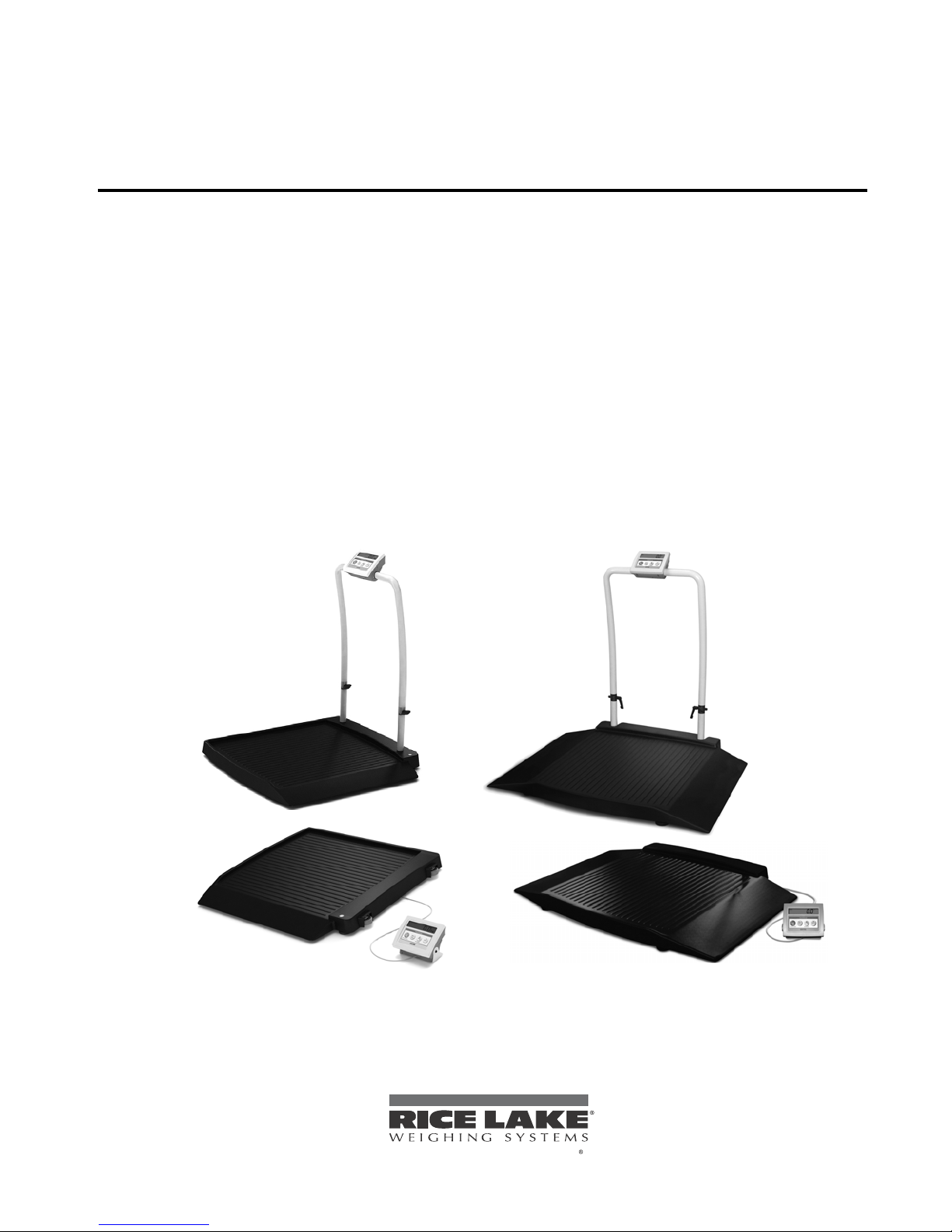
Rice Lake Digital Wheelchair Scale
To be the best by every measure
340-10 Series
Software Revision 11387
Technical and Operating
Instructions
118580
Page 2

Page 3

Contents
Technical training seminars are available through Rice Lake Weighing Systems.
Course descriptions and dates can be viewed at www.ricelake.com or obtained
by calling 715-234-9171 and asking for the training department
1.0 Introduction.................................................................................................................................. 1
2.0 Scale Assembly ........................................................................................................................... 2
2.1 Unpacking Your Scale . . . . . . . . . . . . . . . . . . . . . . . . . . . . . . . . . . . . . . . . . . . . . . . . . . . . . . . . . . . . 2
2.2 Repacking . . . . . . . . . . . . . . . . . . . . . . . . . . . . . . . . . . . . . . . . . . . . . . . . . . . . . . . . . . . . . . . . . . . . . 2
2.3 Setting Up Your Scale . . . . . . . . . . . . . . . . . . . . . . . . . . . . . . . . . . . . . . . . . . . . . . . . . . . . . . . . . . . . 3
2.4 Attaching the Feet to the Scale. . . . . . . . . . . . . . . . . . . . . . . . . . . . . . . . . . . . . . . . . . . . . . . . . . . . . . 4
2.5 Hooking up the AC Power Connections . . . . . . . . . . . . . . . . . . . . . . . . . . . . . . . . . . . . . . . . . . . . . . . 6
2.6 Getting Ready to Weigh a Patient . . . . . . . . . . . . . . . . . . . . . . . . . . . . . . . . . . . . . . . . . . . . . . . . . . . . 6
3.0 Scale Operation ........................................................................................................................... 7
3.1 Weighing a Patient . . . . . . . . . . . . . . . . . . . . . . . . . . . . . . . . . . . . . . . . . . . . . . . . . . . . . . . . . . . . . . . 7
3.2 Using the Body Mass Index (BMI) Function. . . . . . . . . . . . . . . . . . . . . . . . . . . . . . . . . . . . . . . . . . . . . 8
3.3 Using the Tare Function . . . . . . . . . . . . . . . . . . . . . . . . . . . . . . . . . . . . . . . . . . . . . . . . . . . . . . . . . . . 9
4.0 Scale Configuration ................................................................................................................... 10
4.1 Enabling Configuration or Calibration Modes . . . . . . . . . . . . . . . . . . . . . . . . . . . . . . . . . . . . . . . . . . 10
4.2 Configuration Mode . . . . . . . . . . . . . . . . . . . . . . . . . . . . . . . . . . . . . . . . . . . . . . . . . . . . . . . . . . . . . 10
4.3 Numeric Data Entry . . . . . . . . . . . . . . . . . . . . . . . . . . . . . . . . . . . . . . . . . . . . . . . . . . . . . . . . . . . . . 11
4.4 Reset To Factory Defaults . . . . . . . . . . . . . . . . . . . . . . . . . . . . . . . . . . . . . . . . . . . . . . . . . . . . . . . . 15
5.0 Scale Calibration ....................................................................................................................... 16
6.0 RS-232 Communication............................................................................................................. 17
6.1 Pushbutton Keypad Print . . . . . . . . . . . . . . . . . . . . . . . . . . . . . . . . . . . . . . . . . . . . . . . . . . . . . . . . . 17
6.2 Standard Remote Protocol (configuration option #9 set to 1) . . . . . . . . . . . . . . . . . . . . . . . . . . . . . . 17
6.3 ESC Protocol (configuration option #9 set to 0) . . . . . . . . . . . . . . . . . . . . . . . . . . . . . . . . . . . . . . . . 18
6.4 Sample and Explanation of ESC Protocol . . . . . . . . . . . . . . . . . . . . . . . . . . . . . . . . . . . . . . . . . . . . . 21
7.0 Troubleshooting and Testing ..................................................................................................... 23
7.1 Test Mode . . . . . . . . . . . . . . . . . . . . . . . . . . . . . . . . . . . . . . . . . . . . . . . . . . . . . . . . . . . . . . . . . . . . 24
8.0 Maintenance .............................................................................................................................. 26
8.1 Basic Maintenance . . . . . . . . . . . . . . . . . . . . . . . . . . . . . . . . . . . . . . . . . . . . . . . . . . . . . . . . . . . . . . 26
8.2 Cleaning . . . . . . . . . . . . . . . . . . . . . . . . . . . . . . . . . . . . . . . . . . . . . . . . . . . . . . . . . . . . . . . . . . . . . . 26
8.3 Trimming Procedure . . . . . . . . . . . . . . . . . . . . . . . . . . . . . . . . . . . . . . . . . . . . . . . . . . . . . . . . . . . . . 27
9.0 Wheelchair Scale Specifications.............................................................................................. 29
For More Information ............................................................................................................................. 30
Digital Wheelchair Scale Limited Warranty.......................................................................................... 31
© 2012 Rice Lake Weighing Systems. All rights reserved. Specifications subject to change without notice.
Series 340-10, Software revision 11387
January 2012
Page 4

ii Wheelchair Scale Technical and Operating Instructions
Rice Lake continually offers web-based video training on a growing selection
of product-related topics at no cost. Visit www.ricelake.com/webinars.
Page 5
1.0 Introduction
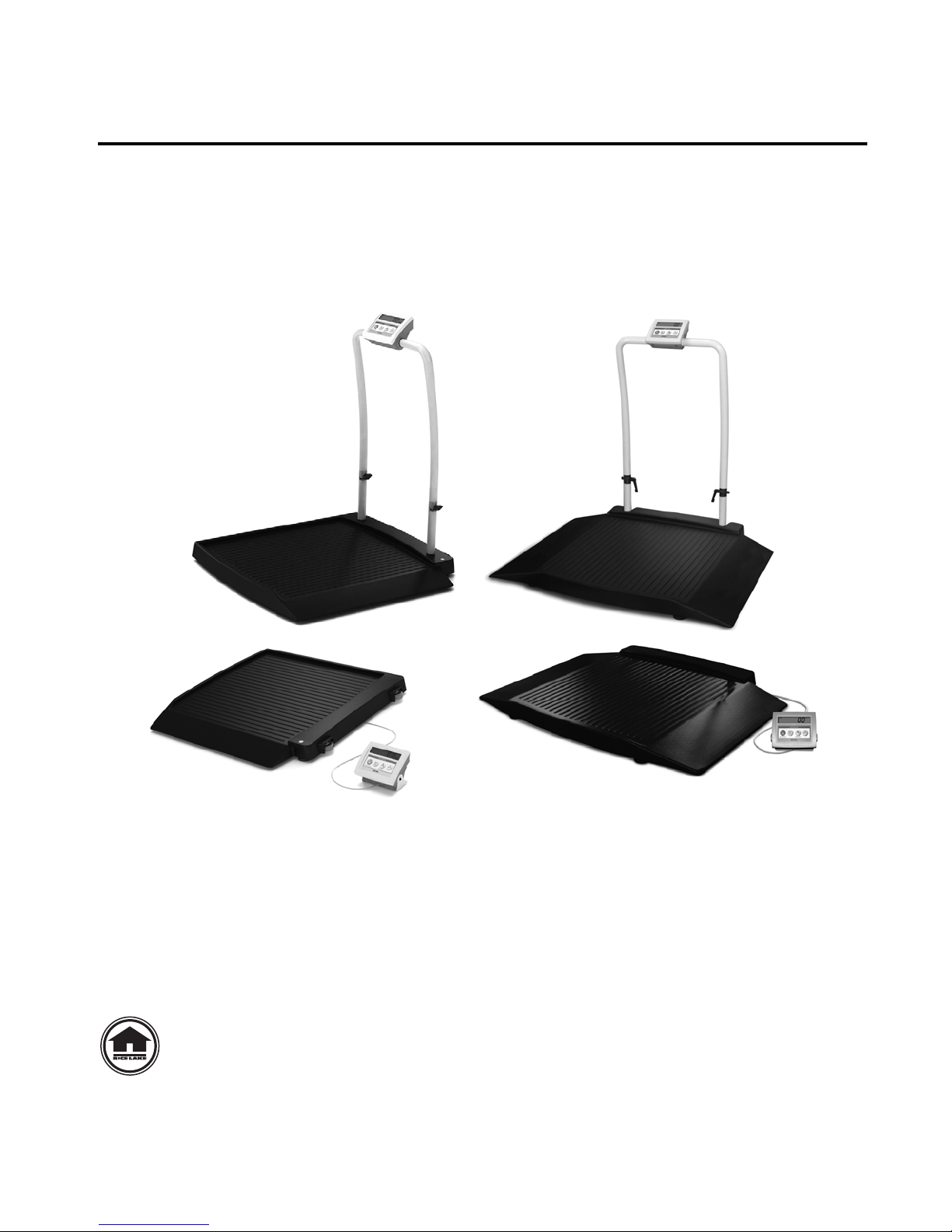
Model 340-10-2
Model 340-10-7
Model 340-10-3
Model 340-10-8
Intern et
The Rice Lake Digital Wheelchair Scale from Rice Lake is a user-friendly, quality scale, designed for safe
weighing of the handicapped and mobility challenged individuals. Movement compensation technology ensures
sound, accurate weighments. The scale has roll on ramp access and comes in four different configurations:
• Single ramp wheelchair scale
• Single ramp platform wheelchair scale
The scale has a non-skid rigid platform and two rear heavy duty wheels for easy maneuverability.
• Dual ramp wheelchair scale
• Dual ramp platform wheelchair scale
Figure 1-1. Digital Wheelchair Scale (single ramp and dual ramp models shown)
The scale is set up to use motion sensing technology, to determine actual weight of a moving patient. The weight
can be displayed in either pounds or kilograms and you can enter a tare weight. The scale operation section on
page 8 of this manual explains the scale operation and how to obtain a tare weight.
The wheelchair scale has a unique folding feature that enables easy transportation and simplifies assembly,
avoiding the need for field wiring and recalibration. All that is required is to open the packaging and unfold the
scale.
Place a known weight on each corner of the scale. The display should illuminate that known weight. If it does
not, trimming will be required.
1
See “Trimming Procedure” on page 28.
This manual can be viewed and downloaded from the Rice Lake Weighing Systems
web site at www.ricelake.com/health. Technical information on these products and
other medical products are available on the Rice Lake Weighing Systems web site.
Rice Lake Weighing Systems is an ISO 9001 registered company.
Page 6
2.0 Scale Assembly
Note
2.1 Unpacking Your Scale
Place the unopened box in an open area that has ample room for unpacking the scale.
Recommended tools needed to set up your scale include:
• Scissors or a box cutter
Using scissors or a box cutter, cut the strapping bands that secure the box together. Immediately after opening the
box, visually inspect your scale to ensure all parts are included and undamaged.
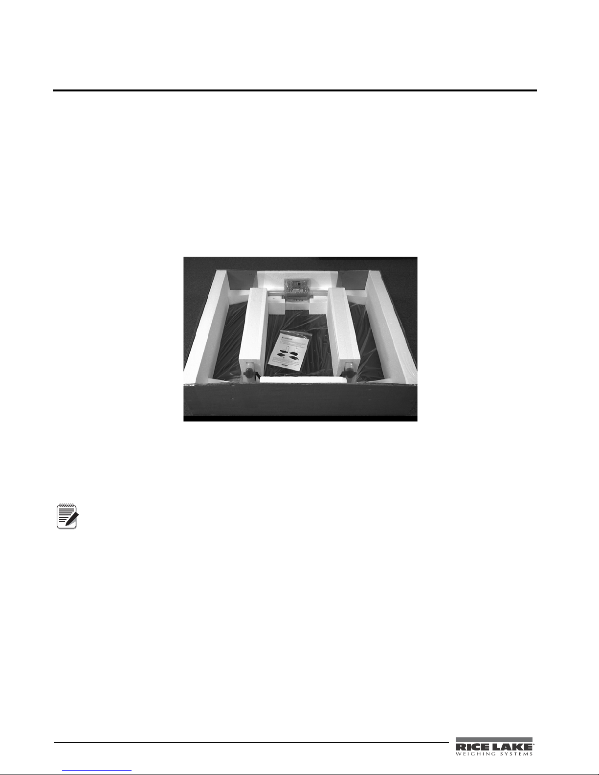
Parts contained in the shipping box include:
• The scale
• This manual
• Small box containing AC adaptor, RS-232 cable, and scale feet
Figure 2-1. Box Contents Including the Scale Surrounded by Styrofoam Packing Material
2.2 Repacking
If the Digital Wheelchair Scale must be returned for modification, calibration or repair, it must be properly
packed with sufficient packing materials. Whenever possible, use the original carton when shipping the scale
back.
Damage caused by improper packaging is not covered by the warranty.
2 Wheelchair Scale Technical and Operating Instructions
Page 7
2.3 Setting Up Your Scale
Note
Use the following steps to set up the Digital Wheelchair Scale.
1. Locate the users manual from inside the box and set aside as it will provide instructions on the proper
scale removal and set up.
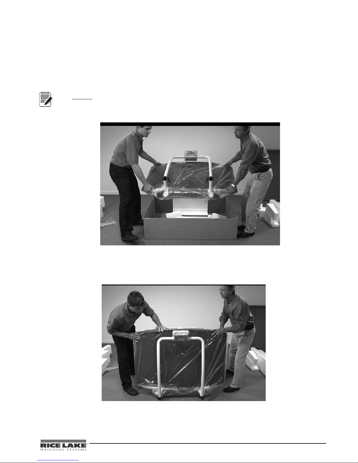
2. Using two people, remove the scale out of the packaging material that it came in by lifting the scale out
of the box by the scale base as shown in
DO NOT lift the scale out of the box by its handle as this can cause the hinges to break or affect the scale
operation.
.
Figure 2-2.
Figure 2-2. Lift the Scale From the Box
3. Move the scale into the area where the weighing process will occur. It’s recommended to place the scale
on a hard, level surface for the most accurate weighments. Thin carpeting is fine but not recommended.
4. Stand the scale on its side as shown in Figure 2-3, so that the plastic packaging material can be removed.
Figure 2-3. Remove Plastic Covering Material
Wheelchair Scale Technical and Operating Instructions - Scale Assembly 3
Page 8
2.4 Attaching the Feet to the Scale
Note
Note
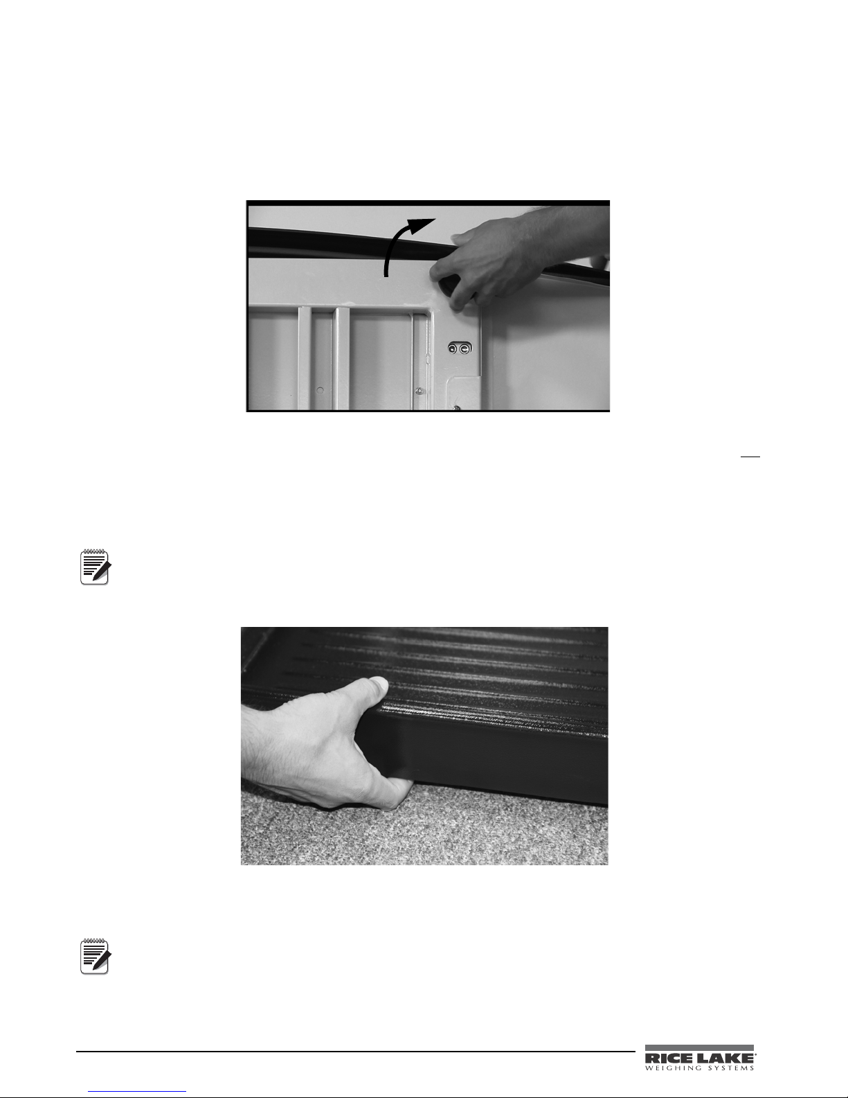
The Digital Wheelchair Scale comes with four feet that must be attached to the scale base for proper operation.
The four feet are located in the parts box in the original shipping box. Use the following steps to attach the feet to
the scale.
1. Screw the four round feet clockwise into the scale base as shown in Figure 2-4.
Figure 2-4. Screw Feet Into the Scale Platform
2. There must be adequate clearance between the scale base and the floor so screw each foot out
counterclockwise two full turns. This will ensure that there is enough clearance between the scale base
and the floor.
3. Gently set the scale base down to the floor. There should be minimal clearance between the scale base
and the floor without having the scale base actually touching the floor. Figure 2-5 shows the width of a
finger being slid under the scale base and the floor.
By not having clearance around the scale base will create inaccurate weighments
Figure 2-5. Have a Minimal Amount of Clearance Between the Scale Base and the Floor
4. It’s also important to make sure that the scale is completely level. Gently press down on all corners of the
scale base to ensure that there are no high spots or rocking of the scale base.
An un-level base will produce inaccurate weight readings.
4 Wheelchair Scale Technical and Operating Instructions
Page 9
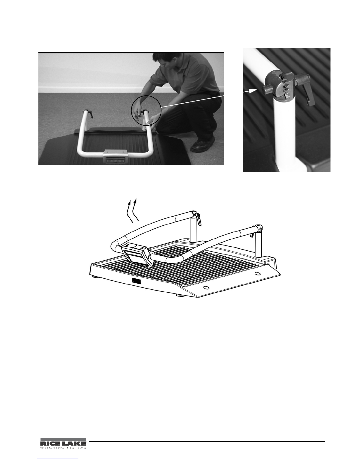
5. Loosen the handles (shown in Figure 2-6) and set upright as shown in Figure 2-7.
Figure 2-6. Loosen the Durable Hinges to Set Handles Upright
6. Tighten the two hinges on the Digital Wheelchair Scale by rotating the two handles. This will secure the
handrail mounted indicator.
Figure 2-7. Set Scale Handles Upright
Wheelchair Scale Technical and Operating Instructions - Scale Assembly 5
Page 10
2.5 Hooking up the AC Power Connections
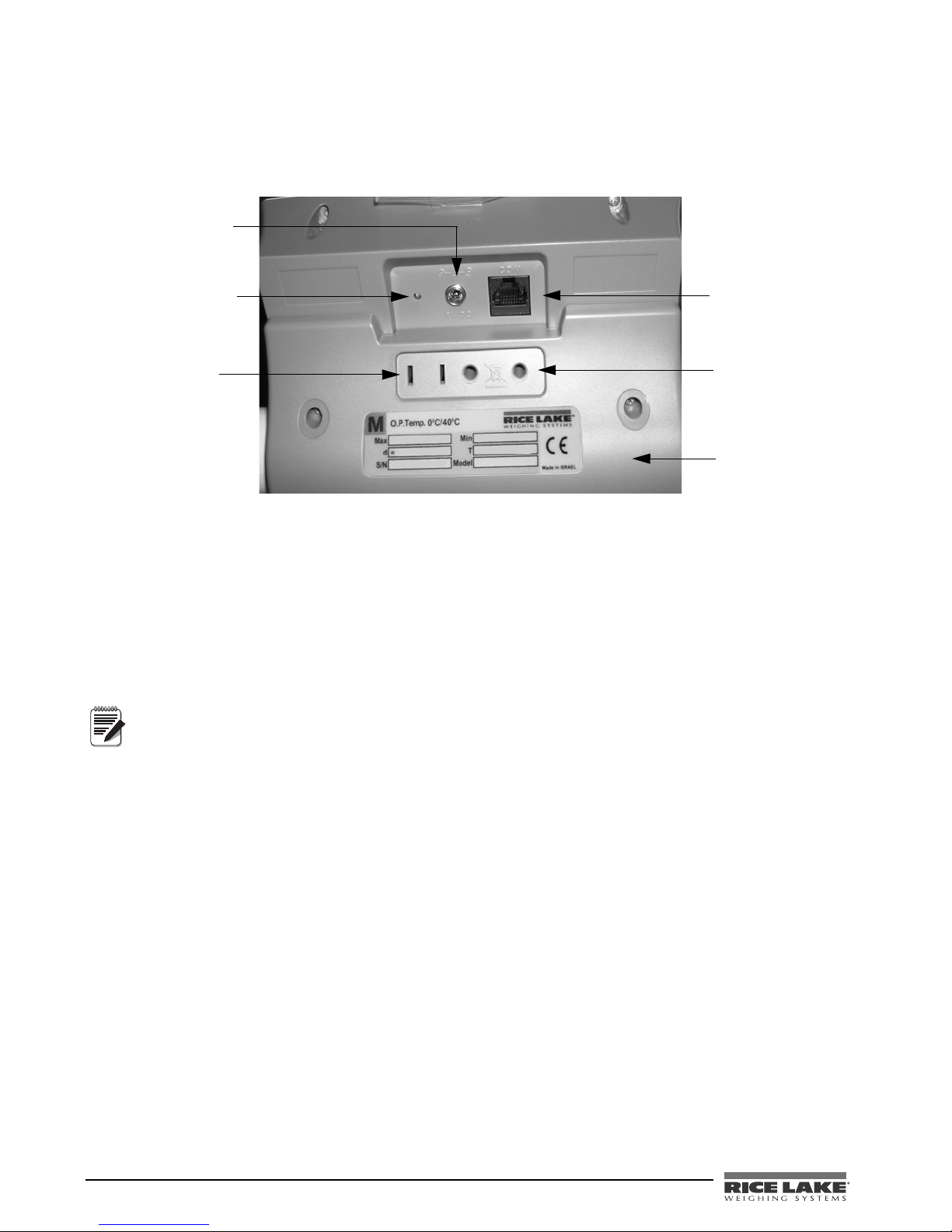
Connect the AC power
source here
LED indicator light
illuminates from red to
green when charged
Store the 120 VAC
adaptor here when
not in use
RS-232 port
connection
Store the 230 VAC
adaptor here when
not in use
Back cover to
indicator
Note
The Digital Wheelchair Scale has a 120 VAC adaptor or 230 VAC adaptor to use when power is readily available.
The AC power adaptor plugs into the back of the indicator as shown in
.
Figure 2-8. LED Light Location
The AC adaptor, when not in use, plugs into the back housing of the indicator for storage. Figure 2-8 shows that
location.
The Digital Wheelchair Scale is capable of running its internal sealed lead-acid rechargeable battery if no
additional power source is available. Battery life is approximately 75 hours. If the
the display, recharge the battery or connect the scale to an AC power source as soon as possible for accurate
weighing.
Figure 2-8.
LO Bat indicator is showing on
Battery Charging
When the AC adaptor is connected to a power source, the rechargeable battery goes into recharge mode.
The LED indicator light on the back of the scale housing will illuminate red during the charging period, and
change over to green when the battery becomes fully charged.
To maintain battery longevity we recommend you charge it on a regular basis rather than waiting until it is
fully discharged.
6 Wheelchair Scale Technical and Operating Instructions
Page 11
2.6 Getting Ready to Weigh a Patient
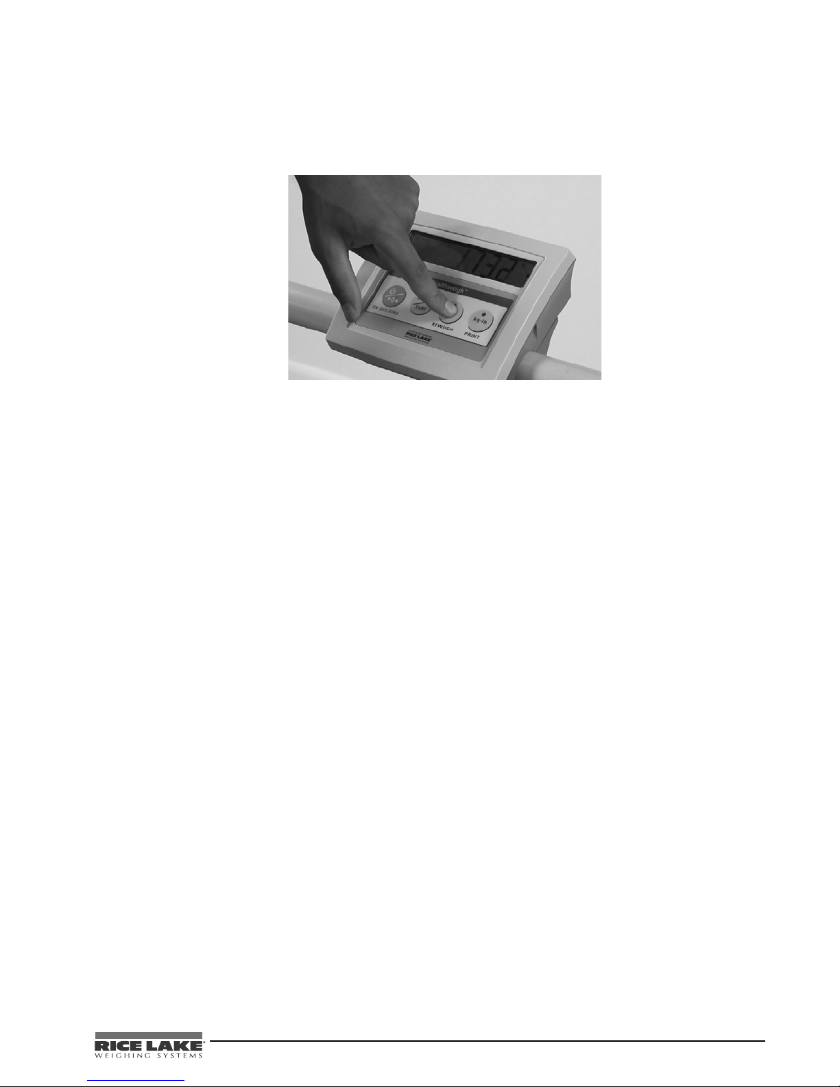
Once the scale is properly unpacked and set up, and prior to weighing a patient, step on the scale to check the
scale that all functions are working correctly. The scale is calibrated from the factory so simply turn on the scale
and step on the scale to get a weight reading. Press the REWEIGH key again to verify that weight.
Figure 2-9. Press The Reweigh Key to Verify Weight
Wheelchair Scale Technical and Operating Instructions - Scale Assembly 7
Page 12
3.0 Scale Operation
Caution
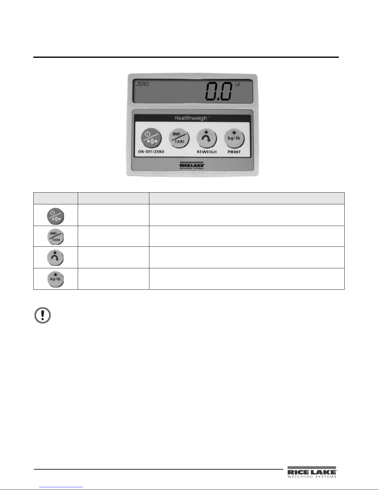
The display has various front panel keys. They are shown below and their function is described in 3-1.
Figure 3-1. Front Panel Display Keys
Key Name Function
ON-OFF/ZERO ON-OFF - Switches the scale on or off.
ZERO - Clears weight off the scale and returns it back to zero.
BMI/TARE BMI - Enables the user to access the BMI (Body Max Index) function.
TARE - Used to subtract a weight off the scale ie: wheelchair.
REWEIGH Allows you to reweigh a patient without having them leave the scale.
Kg-Lb/PRINT Allows the user to toggle between kilograms and pounds.
Press this key to print a weight if connected to a printer.
Table 3-1. Key Functions
The keys on the front panel display are very sensitive so only a gentle pushing motion is required to
obtain results.
The scale has the capability of performing different operations beyond just calculating weight. The various
operating instructions are described below.
3.1 Weighing a Patient
Use the following steps to weigh a person.
1. Press the On-Off/Zero key to turn on the scale and 0.0 will appear on the display.
2. Wheel the patient onto the scale. The display shows WEIGH, then the patient’s weight, and beeps to
indicate the end of the weighing process.
3. To ensure an accurate weighing, press the REWEIGH key.
4. To change the display from Kg to Lb and vice-versa, press the Kg-Lb key.
5. The scale is set to lock in the weight when the weighing process is complete. The weight will remain on
the display even after the patient exits off the scale. To clear the weight, press the
6. To turn off the scale, press and hold the On-Off/Zero key until OFF appears on the display.
On-Off/Zero key.
8 Wheelchair Scale Technical and Operating Instructions
Page 13
3.2 Using the Body Mass Index (BMI) Function
Body mass index (BMI) is the relationship between weight and hei ght associated with body fat an d he alth risk. It
is a reliable indicator of body fatness for people and even though BMI does not measure body fat directly,
research has shown the BMI correlates to direct measures of body fat. BMI is an inexpensive and
easy-to-perform method of screening for weight categories that may lead to health problems for adults.
Calculating BMI is one of the best methods for population assessment of overweight and obesity. Because
calculation requires only height and weight, it is inexpensive and easy to use for clinicians and for the general
public. The calculation is based on the following formulas:
Calculate BMI by dividing weight in pounds (lbs) by height in inches (in) squared and multiplying by a
conversion factor of 703.
Example: weight = 150 lbs, height = 5’5 (65")
Calculation: [150 ÷ (65)2] x 703 = 24.96
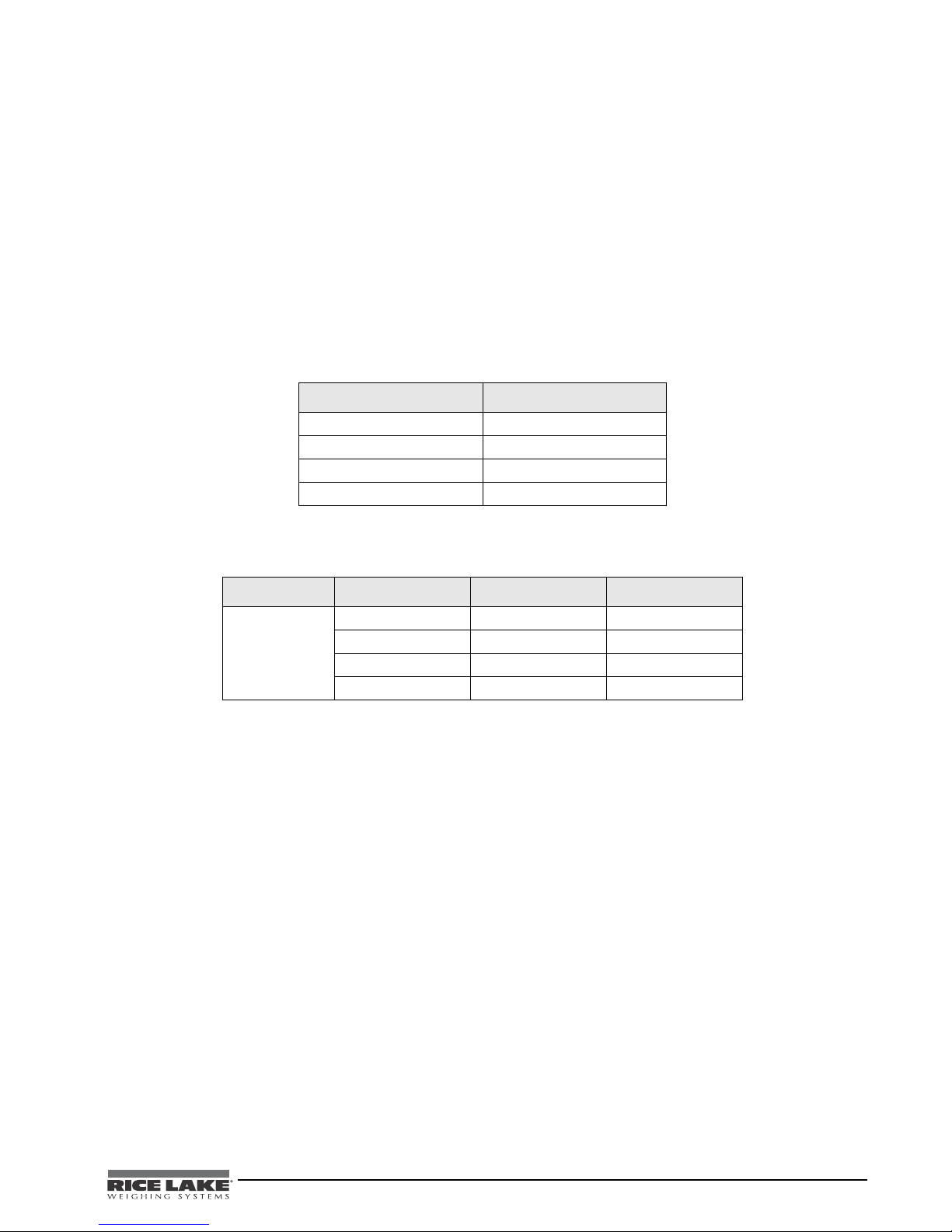
The standard weight status categories associated with BMI ranges for adults are shown in the following table.
BMI Weight Status
Below 18.5 Underweight
18.5 - 24.9 Normal
25.0 - 29.9 Overweight
30.0 and Above Obese
Table 3-2. Standard Weight Status
The following examples show weight ranges, the corresponding BMI ranges and the weight status categories for
a sample height.
Height Weight Range BMI Weight Status
5’9” 124 lbs or less Below 18.5 Underweight
125 lbs to 168 lbs 18.5 to 24.9 Normal
169 lbs to 202 lbs 25.0 to 29.9 Overweight
203 lbs or more 30 or higher Obese
Table 3-3. BMI Ranges and Weight Status Example
Use the following steps in determining the BMI.
1. To use the BMI function, weigh the patient as described under Weighing and then press the BMI key. If
weighing in Lbs, the default height of (5 feet) appears on the display. Use the up or down arrows to
increase the feet height by one foot increments). Press the
BMI key again to display inches (default is 7.0
inches) Again, use the up or down arrows to increase or decrease the inches height by 0.5" increments.
Press the
BMI key again to accept the inches value. The final height value will be displayed ie: 5-07.5 =
5’ 7.5".
2. If you are weighing in Kgs, the default will be 170.0 cm. Use the up or down arrows to increase or
decrease by 0.5 cm increments.
3. To see the patient’s calculated BMI, press the BMI key again. The BMI appears.
4. To cancel the BMI display, press the BMI key.
Wheelchair Scale Technical and Operating Instructions - Scale Operation 9
Page 14

3.3 Using the Tare Function
Note
You can use the tare function for deducting an extra weight (such as a wheelchair, or medical equipment attached
to the patient) in a weighing operation.
To get the most accurate reading, always use the same equipment for pre-weighing (getting the tare
weight) which includes things like the wheelchair footrests, blankets, etc.
Determining a Tare
Use the following steps to use the tare function.
1. With the scale set to 0.0, place the extra load (wheelchair) on the scale. The display shows WEIGH and
then the weight of the wheelchair.
2. Press and hold the TAR E key until TARE appears on the display. The display returns to 0.0 and TARE
appears on the left side of the display.
3. Remove the wheelchair from the scale. The weight of the wheelchair appears with a negative symbol to
the left of it.
4. Wheel the patient onto the scale. The display then shows the patient’s weight without the weight of the
wheelchair.
5. The weight of the wheelchair remains stored in memory, so you can continue to weigh patients who are
carrying the same tare weight. For example, when using the same wheelchair for weighing more than
one patient.
6. To cancel the tare weight, press and hold the TA RE key until TARE disappears from the display and the
display returns back to 0.0. The tare weight is also cancelled when the scale is turned off.
Entering a Known Tare Manually
Use the following steps to enter a tare without placing that item on the scale. An example of this would be if
you’ve got a patient in a wheelchair and the wheelchair has a known weight (has been tagged) you can enter that
weight manually.
1. With the scale set to 0.0 Lbs (there must be no weight on the scale), press the TAR E key. The display will
alternate between a value and the word TARE .
2. T o change the value, press and hold the Kg/Lb key until the right most digi t is equal to the first digit of the
value you want. Example: If you want 103.5, hold the key until the display is
3. T o advance to the next digit, press the Kg/Lb key twice quickly. The digit you changed will move left and
the right most digit will again be 0. Again, hold the Kg/Lb key until the right most digit is equal to the
next digit in the numbers you want.
4. Continue as in Step 3 until you are displaying the value you want, then press the TAR E key.
5. You can now accurately weigh the patient.
6. To cancel the tare weight, press and hold the TA RE key until TARE disappears from the display and the
display returns back to
0.0. The tare weight is also cancelled when the scale is turned off.
0.1.
10 Wheelchair Scale Technical and Operating Instructions
Page 15
4.0 Scale Configuration
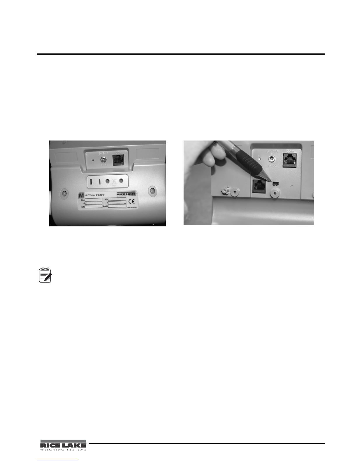
Remove retaining screws x 4 (only 2 shown)
Remove jumper to gain access to
configuration and calibration modes
Note
Options and parameter setup are done through the scale configuration section and is used for setting values and
various parameters and options that are essential for the functioning of the system. Entry into this mode is
possible only when the scale is turned off.
4.1 Enabling Configuration or Calibration Modes
Before the scale will enter either the Configuration or Calibration mode, the configuration enable jumper must be
removed.
Access to that jumper is gained by removing the back cover of the indicator. Remove the four back cover
retaining screws as shown on the left side of
through the hole in the rear housing (shown in Figure 4-1 - right side). Remove that jumper to gain access to the
configuration and calibration modes.
Figure 4-1. With the cover removed, the jumper can be seen sticking
Figure 4-1. Gain Access to the Configuration/Calibration Enable Jumper on the Back of the Indicator
After configuration or calibration is done, the jumper must be replaced for normal scale operation.
A display of Con En indicates that the jumper is not in place. Put jumper on both pins to return the scale
to normal weigh mode.
4.2 Configuration Mode
To get into the configuration mode, turn the scale off and remove the configuration jumper as shown in
Figure 4-1. Turn the scale on. While Start is displayed, press and hold the Kg-Lb key until IDENT appears on the
display.
To change from one parameter to the next, press the REWEIGH key once.
To change the value of the parameter, use the Kg-Lb key.
From the SAVE phase: to save the configuration data, press the REWEIGH key. DONE appears for one or two
seconds followed by
exit with saving changes, press the
Start and the display enter into weighing mode and is ready to start the weighing process. To
Lb/Kg key .
Wheelchair Scale Technical and Operating Instructions - Scale Configuration 11
Page 16

Various parameters can be set up while in programming mode.
Power Off
Power On-Off
START Kg-Lb Key
0.000
Software Version
Round xx
Full xxx
At
Press and
hold
OP1=X
SAVE
T-OFFX
DONE
OP2=X
OP4=X
OP3=X
OP5=X
OP7=X
OP6=X
OP8=X
Press and
hold the
Kg-Lb key
to advance
to option
2 through
option 8.
= DEF =
A TOLXX
A LEN X
MESS
A TImE XX
BAUD XX
Drange
Software ID
SET=X
OP9=X
OP10=X
Limit 0.0
4.3 Numeric Data Entry
Use the Kg-Lb key to change the numeric data entry while setting up the various configuration parameters and
while in calibration mode.
Use the following steps:
1. Press and hold the Kg-Lb key, the rightmost digit on the display will begin to increment.
2. Release the Kg-Lb key to stop the increments.
3. A double click on the Kg-Lb key will cause the right hand digit to move one place to the left.
4. Repeat steps 1-3 until the desired number is reached.
Figure 4-2. Programming Mode Menu Structure
12 Wheelchair Scale Technical and Operating Instructions
Page 17
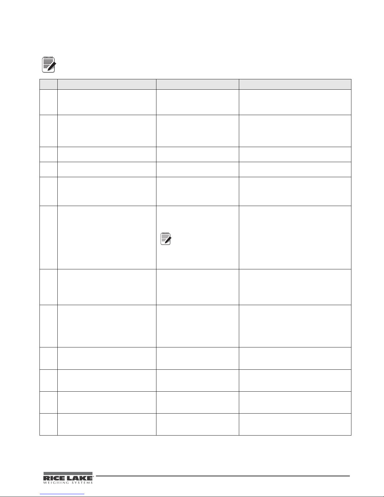
The following table lists the various display messages and sequence when setting up the scale.
Note
Note
<-> means that you can toggle between two values.
Step Function Display Available Parameters
1
*With the scale turned off, remove the
confiiguration jumper as shown in
Figure 4-1.
2 Enters into programming mode
StArt Scale automatically advances to Step 3.
Allows the scale to enter into either
configuration or calibration mode.
*With the scale turned off,
simultaneously press the
and Kg-Lb key.
3 Indentifies the software ID IdEnt<->11007 Press the REWEIGH key to advance to the
4 Identifies software version Id<->11387 Press the REWEIGH key to advance to the
5 Allows selection of decimal point
setting
6 This indicates the maximum allowed
weight. Any weight above this value will
cause StOP to appear on the display
while in the weighing mode.
7 This limit defines the start of the
weighing threshold to compensate for
a key press during the Tare function.
8 Display divisions rOUnd<->XXXX
9 Double ranges limit drAnGe <-> 0 This parameter is preset from the factory. To
10 Weight algorithm initial tolerance A tOL <-> 10 This parameter is preset from the factory. To
11 Weight algorithm initial exponent A LEn <-> 8 This parameter is preset from the factory. To
12 Weight algorithm maximal exponent A t INE <-> 10 This parameter is preset from the factory. To
On-Off/Zero
Table 4-1. Configuration Mode Menu
next step.
next step.
dOt<->000.0
Default = 0.0
FULL<->XX.XXX
Default= 600 Lb
This value is
dependent on the
model you have.
Refer to the serial number
label on your scale and set
appropriately.
Limit<->0.0 Use the numeric data entry (See “Numeric
Default = 0.2 Lb
To change the position of the decimal point,
press the Kg-Lb key to toggle through the
various options. To advance to the next step,
press the
Use the numeric data entry (See “Numeric
Data Entry” on page 12.) to change the
value. To advance to the next step, press the
REWEIGH key.
Data Entry” on page 12.) to see the
optimum weight value of 5 lbs.
To advance to the next step, press the
REWEIGH key.
To change the display divisions, press the
Kg-Lb key to toggle through the various
options.
0.2, 0.5, 1.0, 2.0, 5.0, 10.0, 20.0.
To advance to the next step, press the
REWEIGH key.
advance to the next step, press the
REWEIGH key.
advance to the next step, press the
REWEIGH key.
advance to the next step, press the
REWEIGH key.
advance to the next step, press the
REWEIGH key.
REWEIGH key.
Wheelchair Scale Technical and Operating Instructions - Scale Configuration 13
Page 18

Step Function Display Available Parameters
Note
13 Message style on weight algorithm MESS <-> WEIGH This displays the message that will show on
the indicator display. To change the
Kg-Lb key.
Kg-Lb key
Kg-Lb key
Kg-Lb key
14 This allows for setting the baud rate of
the RS-232 connection
15 Optional features
Option 1 allows the selection of unit of
measure (UOM) in calibration and
programming.
Option 2 allows the scale to work only
in Kg.
Option 3 allows the scale to work only
in Lb.
Option 4, the scale must be stable to
show a Kg or Lb weight reading. You
can enable or disable this.
Option 5 allows for live or dynamic
weighing
message, press the
WEIGH,
LIVE,
- - - - - To advance to the next step, press the
REWEIGH key.
BAUd <->
Default - 9600
OP1 = 1 Hold the Kg-Lb key for browsing through
OP2 = 0 Hold the Kg-Lb key for browsing through
OP3 = 0 Hold the Kg-Lb key for browsing through
OP4 = 0 Hold the Kg-Lb key for browsing through
OP5 = 0 Hold the Kg-Lb key for browsing through
To change the baud rate, use the numeric
data entry (
page 12.)
To advance to the next step, press the
REWEIGH key.
the options. Double click on the
to change the options value or
to advance to the next step, press the
REWEIGH key.
OP1 = Unit of measure (UOM) in calibration
and programming.
0=Kg
1=Lb
the options. Double click on the Kg-Lb key
to change the options value or
to advance to the next step, press the
REWEIGH key.
0=Disable
1= Enable
This option works only if Option 3 is disabled
the options. Double click on the Kg-Lb key
to change the options value or
to advance to the next step, press the
REWEIGH key.
0=Disable
1=Enable
the options. Double click on the
to change the options value or
to advance to the next step, press the
REWEIGH key.
0=Disable
1=Enable
the options. Double click on the
to change the options value or
to advance to the next step, press the
REWEIGH key.
0=Disable
1=Enable
See “Numeric Data Entry” on
Won’t show lb or kg until the
scale is at a standstill.
Table 4-1. Configuration Mode Menu
14 Wheelchair Scale Technical and Operating Instructions
Page 19
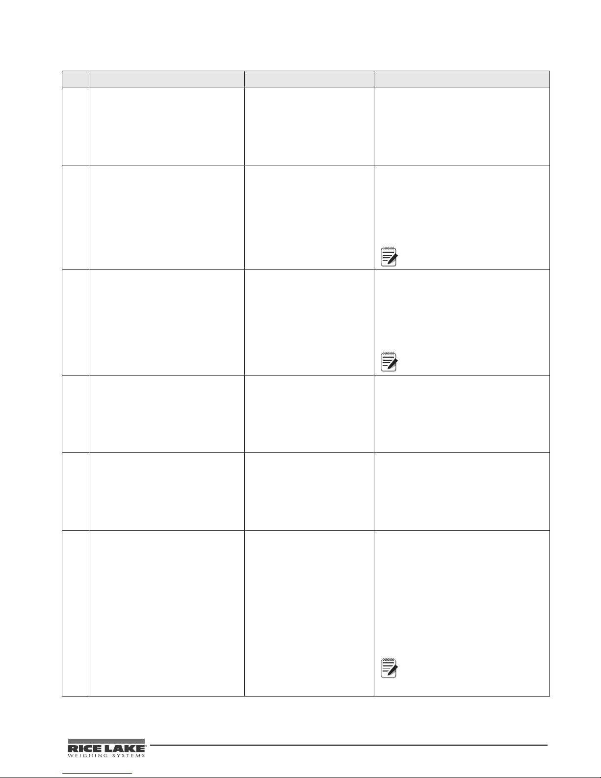
Step Function Display Available Parameters
Note
Note
Note
Option 6 allows you to either enable or
disable the hold function on the scale
Option 7 allows you to either enable or
disable the baby scale function.
OP6 = 1 Hold the Kg-Lb key for browsing through
the options. Double click on the Kg-Lb key
to change the options value or
to advance to the next step, press the
REWEIGH key.
0=Disable
1=Enable
OP7=0 Hold the Kg-Lb key for browsing through
the options. Double click on the Kg-Lb key
to change the options value or
to advance to the next step, press the
REWEIGH key.
0=Disable
1=Enable
Leave set to 0
Option 8 allows you to choose
between 9 volts and 6 volts
Option 9 allows you to select the
communications protocol.
Option 10 allows you to enable the
user menu.
16 Set Option defaults Set < - > 1 To change, press the Kg-Lb key.
OP8 = 1 Hold the Kg-Lb key for browsing through
the options. Double click on the
to change the options value or
to advance to the next step, press the
REWEIGH key.
0=9 volts
1=6 volts
Leave set to 1
OP9 = 1 Hold the Kg-Lb key for browsing through
the options. Double click on the Kg-Lb key
to change the options value or
to advance to the next step, press the
REWEIGH key.
0= escape
1= standard protocol
OP10 = 1 Hold the Kg-Lb key for browsing through
the options. Double click on the
to change the options value or
to advance to the next step, press the
REWEIGH key.
0= enable
1= disable
0 - default
Options = (OPx)
1 = US default (US defaults are OP1-1,
OP2-0, OP3-0, OP4-0, OP5-0, OP6-1,
OP-7-0, OP8-1, OP9-1, OP10-1).
2 = European 1 default
3 = European 2 default
9 = Used if OP1 through OP10 have been
changed to something other than the factory
default settings.
Always set to 1 or 9 for US
indicators. To advance to the
next step, press the REWEIGH
key.
Table 4-1. Configuration Mode Menu
Kg-Lb key
Kg-Lb key
Wheelchair Scale Technical and Operating Instructions - Scale Configuration 15
Page 20

Step Function Display Available Parameters
17 Determines the automatic shut off time
when the scale is not in use. Options
are between one and 20 minutes.
This is used when the unit is battery
operated.
18 StArt or SAvE If no changes were made in the parameters
19 Con En Replace the configuration jumper.
t-OFF <-> 5 Press and hold the Kg-Lb key to scroll
through the furthest right hand digit on the
display (0-9). If you want a value from 10 to
19, with the display sitting at 1, double press
Kg-Lb key and 10 appears. Press and
the
hold the
If you want a value of 20, with the display
sitting at 2, double press the
20 will appear.
To advance to the next step, press the
REWEIGH key.
the display will automatically show
then returns to normal weighing mode.
If a parameter was changed, the display will
show
the REWEIGH key. To return to weigh mode
without saving changes, press the Kg-Lb
key.
Kg-Lb key to begin scrolling 10-19.
Kg-Lb key and
StArt and
SAvE. To save changes made, press
* Indicates procedure to perform.
Table 4-1. Configuration Mode Menu
4.4 Reset To Factory Defaults
The configuration parameters may be reset to factory defaults while in the configuration mode. To do so, enter
the configuration mode. Press the
11305). Press and hold the
function, press the
REWEIGH key and the scale will show DONE, then it will restart. If you do not want to perform
BMI key until =DEF= is displayed. At this point, if you wish to perform the default
the default function, press the
After performing the default function, the scale will require r e-calibration. In addition, the scale will be set
up to a capacity of 600 lbs. The capacity varies by model - refer to the serial label on your scale and
reconfigure the capacity (FULL) and display divisions (rOUnd) as necessary in the configuration menu.
REWEIGH key once to advance to displaying the software version (ID <->
ON/OFF key.
16 Wheelchair Scale Technical and Operating Instructions
Page 21
5.0 Scale Calibration
Note
Before you can calibrate the scale, verify and set all scale parameters which are noted in “Scale Configuration”
on page 11.
Remove the configuration/calibration jumper (see page 11). Turn the scale on. While StArt is displayed, press and
hold both the Kg-Lb key and the REWEIGH keys until CAL is displayed.
To do a calibration on the scale, the scale must be turned off.
The calibration weight must be no less than 60 lb (28 kg) and no more than 300 lb (135 kg).
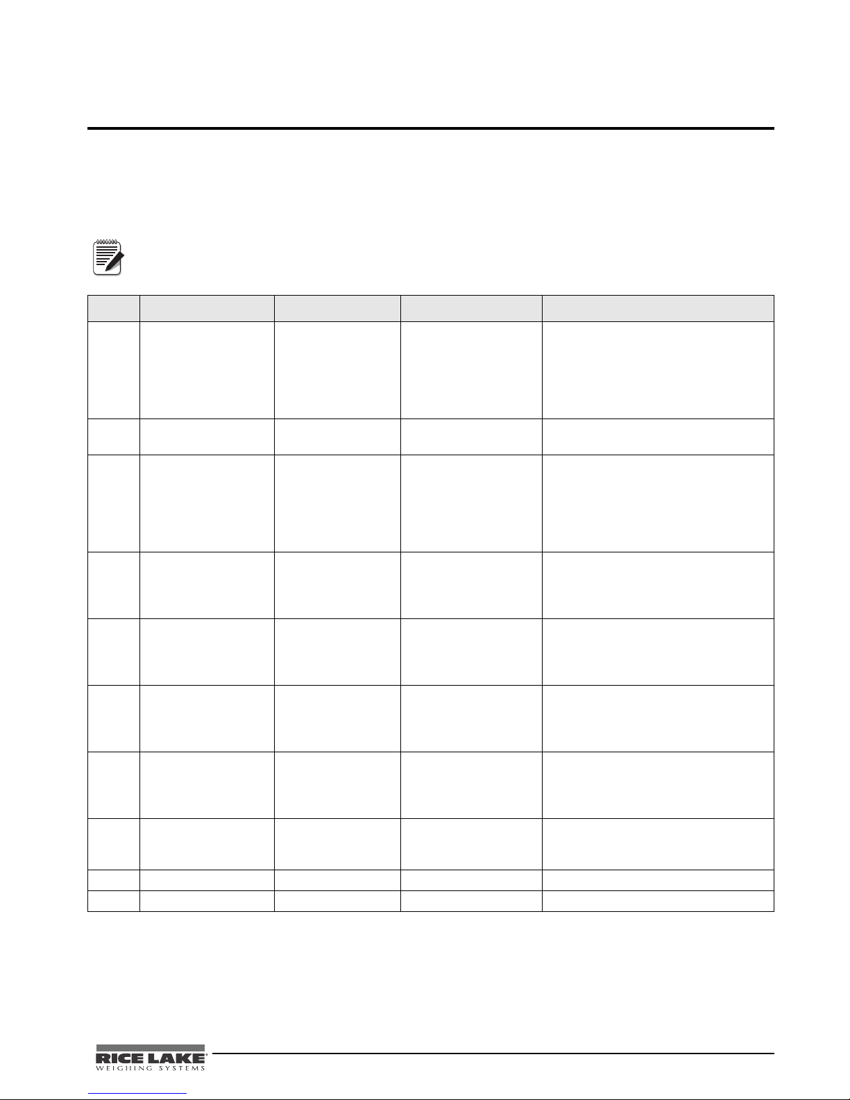
The following chart illustrates the calibration procedure.
Step Function Display Available Parameters
1 Turn the scale on.
While START is
displayed, press and
hold the
REWEIGH keys until
CAL is displayed.
2 Cal mode entered CAL To advance to the next step, press the
3 Sets the value of the
4 CLEAr Clear the platform and be sure of the
5 Calibrate Zero - - - - -
6 Calibrate Span CAL
7 SAvE To save the new calibration, press the
8 dONE The scale displays that it has saved that
9 StArt The scale reboots.
10 Con En Replace the configuration jumper.
Kg-Lb and
Enters into calibration
mode
calibration weight
you are going to use
for calibrating the
span value of the
scale.
StArt The scale automatically advances to
Step 2.
REWEIGH key.
LOAd <-> XXX.X Use the numeric data entry (explained in
“Numeric Data Entry” on page 12) to set
a calibration weight.
To advance to the next step, press the
REWEIGH key.
scale’s stability.
To advance to the next step, press the
REWEIGH key.
Place the requested weight on the scale.
PUT<->XXXX
FAC tOr <-> X.XXX
This will display for a few seconds.
To advance to the next step, press the
REWEIGH key.
This will be displayed for a few seconds
and shows the current calibration factor.
To advance to the next step, press the
REWEIGH key.
REWEIGH key.
To exit without saving the calibration
press the ZERO key.
calibration value and automatically
advances to the last step.
Table 5-1. Calibration Menu
Wheelchair Scale Technical and Operating Instructions - Scale Calibration 17
Page 22

6.0 RS-232 Communication
The scale comes with an RS-232 port which enables weight data to be transmitted to other equipment, such as a
computer or printer. The RS-232 cable with DB-9 connector (PN 100719) is available from Rice Lake Weighing
System.
The RS-232 parameters are 9600 baud (selectable in the programming mode), 8 data bits, 1 stop bit, no parity
and no handshaking.
There are three methods of communication:
6.1 Pushbutton Keypad Print
With a stable, in-range weight, press and hold the Kg-Lb/Print key for at least three seconds, or until the scale
emits two quick beeps. Note that if the scale does not beep after five seconds, then release the button as the
weight was either in motion, or out of range.
xxxxxxxxx<SP>uu<SP>mmmmm<SP><CR><LF>
Where:
Examples:
Figure 2-8 on page 6 shows where the RS-232 connection is.
• Pushbutton keypad print
• Standard remote protocol
• Escape protocol
• If displaying weight and not BMI, the scale will send out the following 21 character string:
xxxxxxxxx is the weight with decimal point and " - " sign, if negative uu is the unit (lb or kg).
mmmmm is the mode (gross or net)
-10 Lb net = <SP><SP><SP><SP>-10.0<SP>lb<SP><SP>Net<SP><SP><SP><CR><LF>
10 Lb gross = <SP><SP><SP><SP><SP>-10.0<SP>lb<SP>Gross<SP><CR><LF>
• In BMI mode (displaying the BMI value), the scale will send out the following data:
GROSS WEIGHT 215.0 LB
TARE WEIGHT 0.0 LB
NET WEIGHT 215.0 LB
PATIENT HEIGHT 6-01.0 FT
PATIENT BMI 28.4
6.2 Standard Remote Protocol (configuration option #9 set to 1)
When connected to a computer, there are five commands that can be used in the standard remote protocol to
communicate with the scale. They are:
• t - tare the scale. If in gross mode, will tare and go to net mode. If in net mode, will remove tare and
return to gross mode.
• w - the scale sends the actual weight to the computer.
• i - the scale sends the software ID of the scale.
• z - the scale will be set to zero (0.0) if possible.
• p - the scale sends the same data as a pushbutton keypad print.
The format of the returned data will be the same as noted under the pushbutton keypad print. Note that the w and
p commands will not return a value if the scale is in motion, or displaying an invalid weight.
18 Wheelchair Scale Technical and Operating Instructions
Page 23
6.3 ESC Protocol (configuration option #9 set to 0)
The ESC Protocol differs from the standard protocol and enables weight and unit of measure data to be
transmitted for full integration into electronic medical records or for diagnostic testing of the battery life, load
cells, etc. The scale will only transmit data upon receiving the proper command set.
You can test the command set and review the scales’ response using either PROCOMM Plus or the Dietary/
Fitness files found on our web site, www.ricelake.com/health. If using PROCOMM Plus, we recommend you
set up "hot" keys for the commands. Refer to
An Escape Protocol is where the escape <ESC> is used to indicate that there is a command following and not just
data.
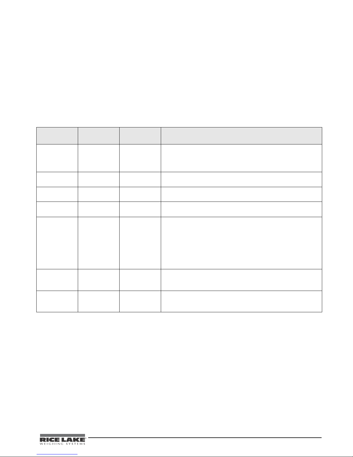
Table 6-1 lists a complete list of ESC commands that are used with the scale.
Table 6-1 for a listing of those commands.
Command/
Response ESC Character
Reading R R This value tells the PC that the scale is sending a reading. Immediately
Weight W Wnnn.n This is the patient’s weight (ie: W0200.5 means 200.5 lb). If the scale is
Units N Nc This indicates in which unit the values have been taken (m=metric,
End of Packet
(EOP)
Diagnostics
(request)
Diagnostics
(response)
Control (set a
value)
E E This indicates that the end of the command/data packet has been
A Accc This is the request for a diagnostic test on certain parts of the scale
Z Zccc This will be the response to the diagnostics done on the scale. Values
C Cccc=c This is to set the value of the scale’s global settings
ESC value with
Parameters
Description
following this will be the value that is sent
Example: <ESC>R<ESC>E
<ESC>R<ESC>W0200.5<ESC>Nm<ESC>E
overloaded, the scale will return the value of 999.9.
c=constitutional
reached
such as the battery life, loadcells, etc.
• AD value (ADC) = E06=AD is too high, E07=AD is too low
• Overload (OVL) = E10
• Battery (BAT) = E4U= (Bat ok) or E4L (Bat Low, but still usable - 1
bar left on the indicator
• Calibration information OK (CAL) = E11=Calibration was not okay
and the user needs to recalibrate.
will include any error codes to indicate what is wrong with the scale, or
all zeros (Z000) to indicate that all is well.
<ESC>CUOM=m<ESC>E will set the unit of measurment to KG
• Unit of measurement (metric or constitutional) (UOM) = c (m or c)
If you’re using the Rice Lake files, please follow the instructions below.
1. Go to www.ricelake.com/health and download the Rswin.exe and Inbar.ini files located in the downloads
section of the web site and download them to your computer.
2. Ensure that the scale is connected to the computer via RS-232 cable.
Table 6-1. RS-232 Communication Parameters
Wheelchair Scale Technical and Operating Instructions - RS-232 Communication 19
Page 24
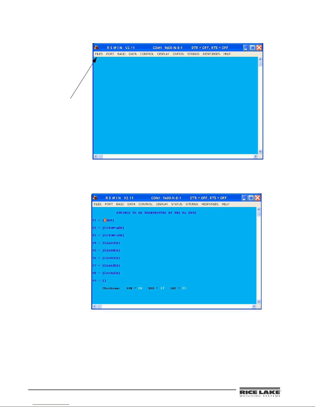
3. Double click on the Rswin.exe file and the following screen appears.
Click on FILES
and in dropdown
menu, select
LOAD
CONFIGURATION
as noted in Step 4
Figure 6-1. Rswin Screen
4. Click on FILES and in the dropdown menu, select LOAD CONFIGURATION. At this time double click on the
file, Inbar.ini.
5. Click on STRINGS and the following screen appears.
Figure 6-2. Strings to be Used in the RS-232 Transmission
This screen is showing that the function keys are already pre-programmed with command sets. For
example, pressing the
6. Click on DISPLAY and in the drop down menu, select either HEX or ASCII.
20 Wheelchair Scale Technical and Operating Instructions
F1 key is the same as sending <ESC>R<ESC>E.
Page 25
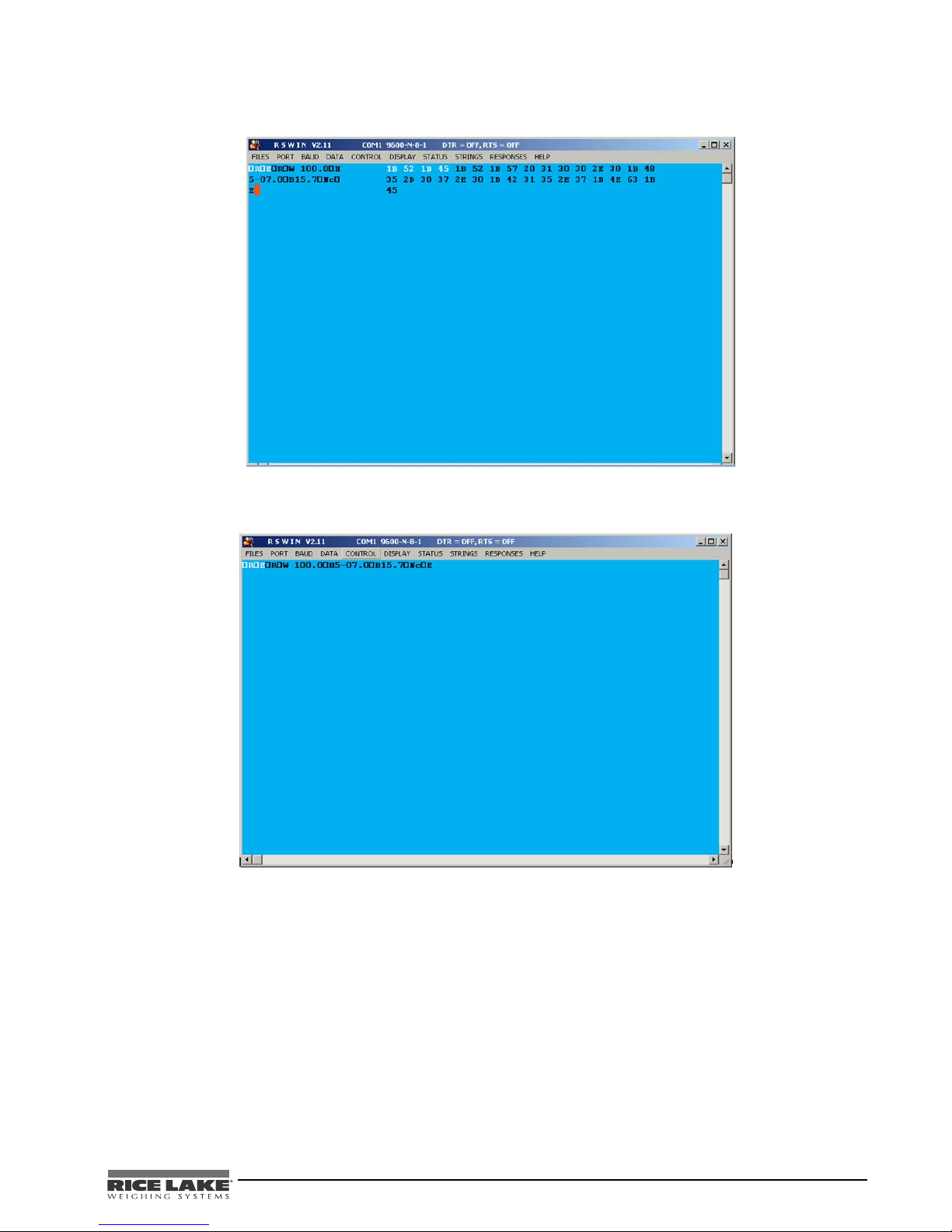
Examples of what you would see in the HEX screen are shown in Figure 6-3.
Figure 6-3. HEX Screen Example
Examples of what you would see in the ASCII screen are shown in Figure 6-4.
Figure 6-4. ASCII Screen Example
Wheelchair Scale Technical and Operating Instructions - RS-232 Communication 21
Page 26
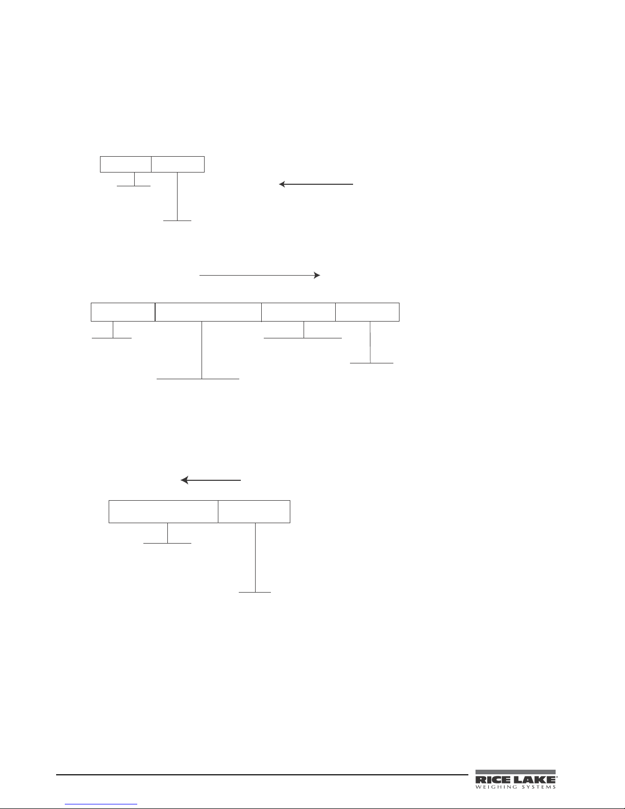
6.4 Sample and Explanation of ESC Protocol
&4$3&4$&
3FBEJOH
SFRVFTU
&01
3#!,%0#
&01
6OJUPG.FBTVSF.FUSJD
&4$3&4$8&4$/N&4$&
3FBEJOH
$PNNBOE
8FJHIU
3#!,%0#
DIRECTIONOFCOMMUNICATION
&4$"#"5&4$&
%JBHOPTFCBUUFSZ
&01
3#!,%0#
DIRECTIONOFCOMMUNICATION
When the scale measures weight and sends this over the communications line to the PC, the string will look like
this.
<SCALE> --------<PC>
When the user wants to diagnose any problems with the scale, the operator will have to ask the scale to send the
error data (if any exists). This is done with the Diagnostics (request) command and will look like this:
22 Wheelchair Scale Technical and Operating Instructions
Page 27

If the battery is okay, the scale will reply with the following value:
&4$;&6&4$&
#BUUFSZJTPLBZ
OPFSSPST
&01
3#!,%0#
DIRECTIONOFCOMMUNICATION
&4$;&-&4$&
#BUUFSZJTWFSZMPX
6OTUBCMF
&01
If the battery is critically low, it will reply with:
Wheelchair Scale Technical and Operating Instructions - RS-232 Communication 23
Page 28

7.0 Troubleshooting and Testing
Refer to the following instructions to check and correct any failure before contacting service personnel.
Symptom Possible Cause Corrective Action
Scale does not turn on Dead battery Connect the scale to a power source.
Faulty electrical outlet Use a different electrical outlet.
Bad power supply Replace adaptor.
Questionable weight or the scale does
not zero
Weighing is performed but the display
shows WEIGH and REWEIGH every few
seconds; the weighing process takes too
long and no weight is displayed
The display shows a STOP message The load on the scale exceeds the
The display shows LO Bat message The battery is low Recharge the battery.
The display shows Err message as
detailed in the table below
Err 2 Low saturation state (low A/D) The load cell is not connected properly.
Err 3 High saturation state (high A/D) See Err 2
Err 6 Unstable weight. Cannot calibrate Check the load cells’ mechanical
Err 7 Mathematical error; division by zero.
Calibration or configuration settings are
messed up
External object is interfering with the
scale
Display did not show 0.0 before
weighing
Scale is not placed on a level floor Ensure the scale is level using the spirit
Scale is out of calibration Check the weight with a known weight
Improper tare Place the patient on the scale. Press
The patient is not sitting still Ask the patient to be still.
capacity of the scale (220 kg)
Cannot calculate calibration factor.
Pushed the wrong keys Reset to factory defaults. See page 16
Remove the interfering object from the
scale.
Help the patient off the scale, zero the
scale and begin the weighing process
again.
level on the platform and begin the
weighing process again.
value.
REWEIGH. Once the weight of the item
is displayed, press
patient back on the scale. Press the
REWEIGH button again.
Remove the excess weight and use the
scale according to manufacture’s specs.
Check the cables and mechanical
connections. If the problem persists,
replace the set of load cells.
surroundings and see that nothing
touches them and that the cables are
properly welded.
This error will show when trying to
calibrate the unit with no calibration
weight on the unit.
for instructions.
TARE . Place the
Table 7-1. Troubleshooting Table for the Rice Lake Scale Line
24 Wheelchair Scale Technical and Operating Instructions
Page 29
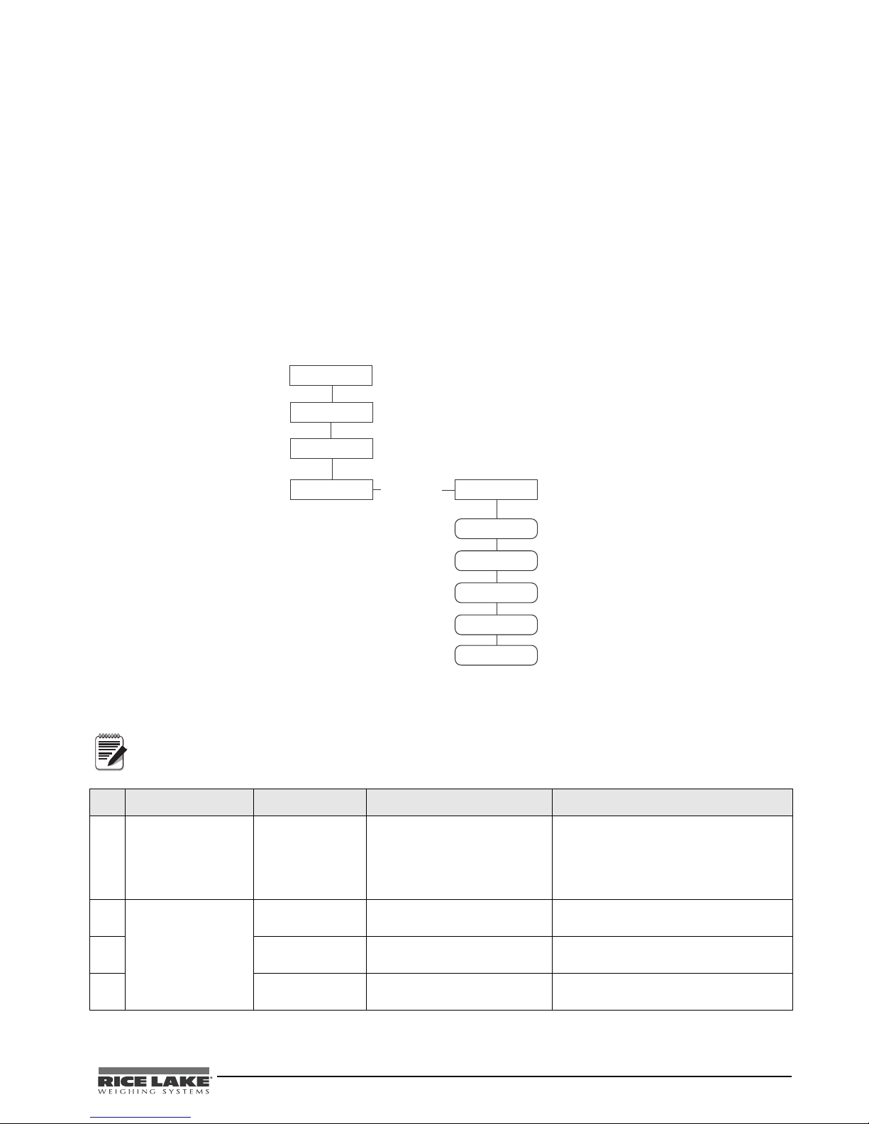
7.1 Test Mode
Power On-Off
START REWEIGH Key
TEST
Version
BAT
A-D
FACTOR
At
Press and
hold
Power Off
Remove Config/
Calibr. Jumper
Note
The test mode menu is a special mode used for checking four very important parameters which are useful in
knowing the system’s state and for troubleshooting. Entry into this mode is possible only when the scale is turned
off. Turn the scale on. While Start is displayed, press and hold the REWEIGH key until both the middle arrows
appear on the display.
The test mode has four parameters. They are:
•Weighing
• Internal count
• Battery indication
• Calibration factor
Alternating between the parameters is performed by pressing the REWEIGH key.
Press the Kg-Lb key to zero the scale in test mode.
Press the Kg-Lb + REWEIGH to exit weighing mode.
Table 7-2 lists the various display messages when testing the scale.
<-> means that you can toggle between the two values.
Step Function Display Available Parameters
1
With the scale turned
off, simultaneously
press the
and On-Off/Zero
keys.
2
3
4
This enters into
REWEIGH
the test mode of
the scale.
Identifies the
software ID
Shows the current
weight value
Shows the current
A/D count
Wheelchair Scale Technical and Operating Instructions - Troubleshooting and Testing 25
Figure 7-1. Test Mode Menu Structure
StArt The scale automatically advances to Step
2.
IdEnt <-> 11007 Press the REWEIGH key to advance to
the next step.
tESt <-> 0.0 To advance to the next step, press the
REWEIGH key.
A-d <-> XXXX To advance to the next step, press the
REWEIGH key.
Table 7-2. Test Mode Menu
Page 30

Step Function Display Available Parameters
5
Checks for current
battery level
bAt <-> XXX or nO bAt If the nO bAt is displayed, there are not
batteries in the unit or the unit is operating
on its external AC adaptor.
To advance to the next step, press the
REWEIGH key.
6
This shows the
calibration factor
FACtOr <-> XXXXX Press the REWEIGH key to return to the
top of the test menu.
To exit test mode, press the REWEIGH
Kg-Lb key simultaneously, or turn off
and
the indicator.
Table 7-2. Test Mode Menu
26 Wheelchair Scale Technical and Operating Instructions
Page 31

8.0 Maintenance
The following section provides instructions for maintaining and cleaning the Rice Lake line of scales.
Maintenance operations other than those described in this section should be performed by qualified service
personnel.
8.1 Basic Maintenance
Before the first use of the scale and after periods of non-use, check the scale for proper operation and function. If
the scale does not operate correctly, contact qualified service personnel.
Go through the following steps for basic maintenance.
1. Check the overall appearance of the entire scale for any obvious signs of damage, abuse, etc.
2. Inspect the condition of the AC adaptor for cord cracking or fraying or for broken or bent prongs.
8.2 Cleaning
Proper care and cleaning is essential to ensure a long life of accurate and effective operation. Before beginning
the cleaning process, disconnect the scale from the AC power source.
1. Clean all external surfaces with a clean, damp cloth or tissue. Mild soap and water solution may be used.
Dry with a clean soft cloth.
2. Do not immerse the scale into cleaning or other liquid solutions.
3. Do not use Isopropyl alcohol or other solutions to clean the display surface.
Wheelchair Scale Technical and Operating Instructions - Maintenance 27
Page 32
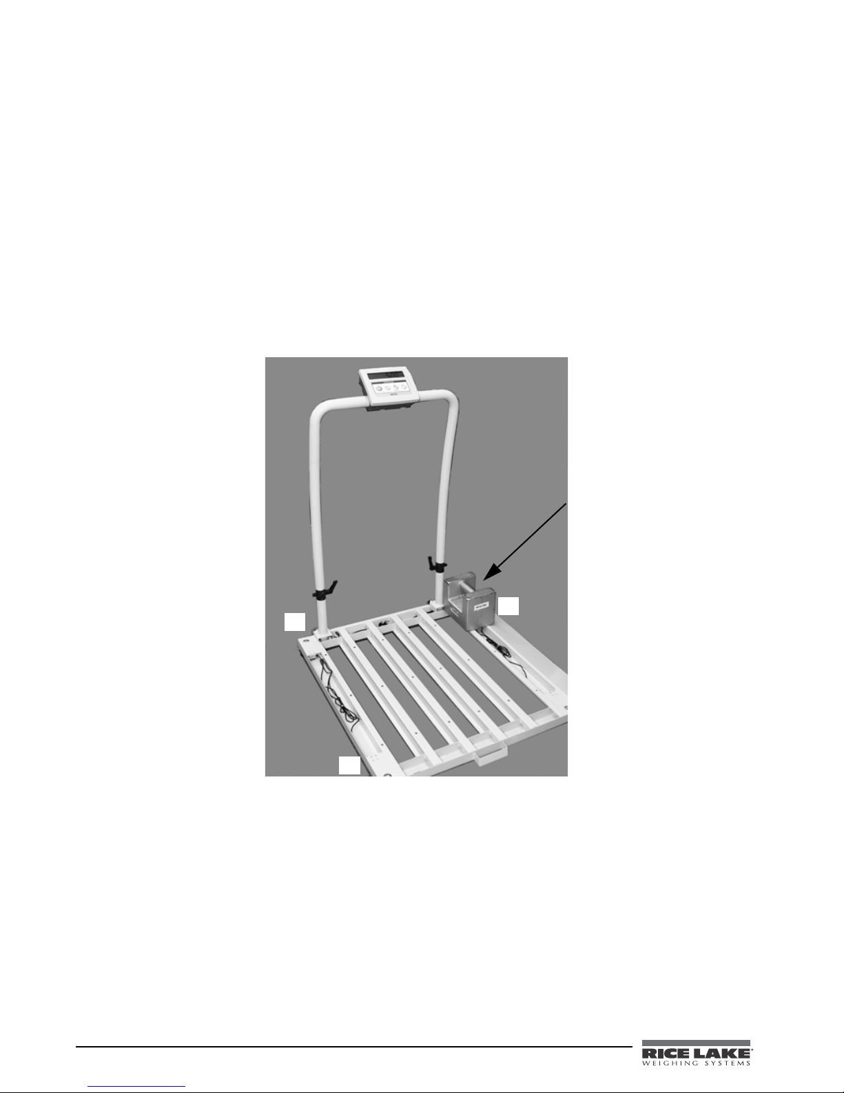
8.3 Trimming Procedure
2
Place a known test weight
on each corner of the scale
directly over the load cell.
Place test weight in the
following numbered
sequence.
4
1
3
Trimming is the process of equalizing the output from multiple individual load cells. If needed, load cells can be
individually trimmed with potentiometers.
Whenever a substantial amount of trim (more than 5% of normal output) seems necessary to equalize output,
check for other possible problems. The best trim is always the least amount of trim. When all errors except load
cell mismatch and cable extensions or reductions have been corrected, continue with the trimming.
Use the following steps to properly trim the scale.
1. Zero the indicator and place a calibrated 70 kg test weight over each load cell in turn as shown below in
Figure 8-1 starting in the following sequence.
• Start with the furthest left hand corner (1)
• Nearest lefthand corner (2)
• Furthest righthand corner (3)
• Nearest righthand corner (4)
Figure 8-1. Wheelchair Trimming Corners Sequence
2. Record the value displayed on the indicator after the test weight is placed in turn on each corner (directly
over the load cell), without allowing the weight to overhang the sides of the scale. Allow the scale to
return to zero each time to check for friction or other mechanical problems. Select the load cell which
has the lowest value as your reference point. This cell will not be trimmed.
28 Wheelchair Scale Technical and Operating Instructions
Page 33
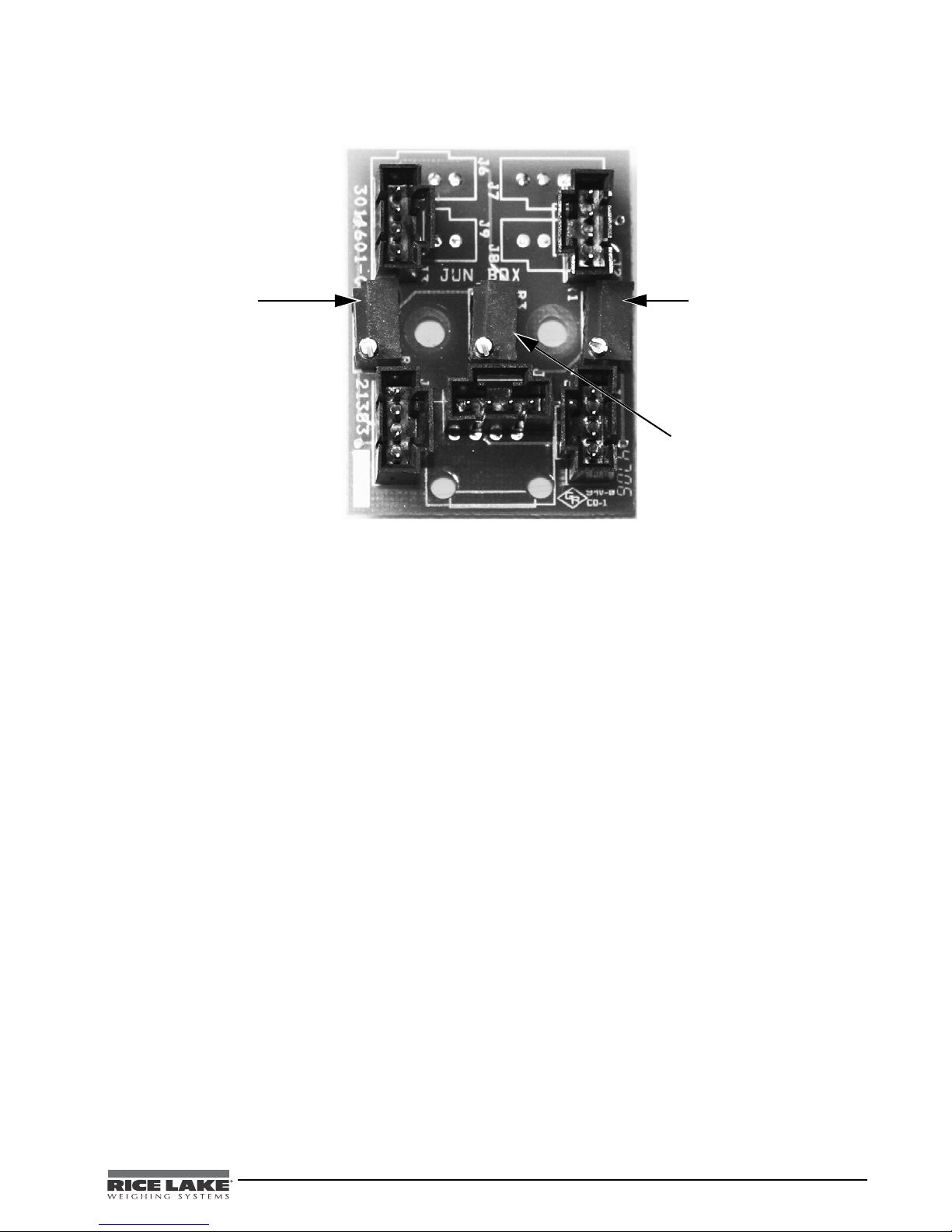
3. Replace the same test load over each cell in turn measuring load cell one (1) and two (2) first and then
Potentiometer for load cells
one (1) and two (2)
Potentiometer for load cells
three (3) and four (4)
Potentiometers for checking
middle beams
using the corresponding potentiometer, turn each cell down to equal the referenced load cell.
Figure 8-2. Load Cell Potentiometers
As the corner corrections are somewhat interactive, check all cells again for repeatability. If necessary repeat
steps 1 through 3 again.
4. Now measure load cell three (3) and four (4) and use the corresponding potentiometer to turn each cell
down the equal the referenced load cell.
5. Now align the two sides of the scale by:
• Place a 70 kg weight in the center of the left hand beam and read the A/D value.
• Place a 70 kg weight in the center of the right hand beam and read the A/D value.
• Turn the corresponding potentiometer until an equal value is reached between the sides with a
margin of 2 units of A/D.
Wheelchair Scale Technical and Operating Instructions - Maintenance 29
Page 34

9.0 Wheelchair Scale Specifications
Power
120 VAC-9VDC-50Hz / 230 VAC-9VDC-50Hz
Battery Type
Sealed lead acid battery
Battery Use
75 hours
Approximately 300-1200 recharge cycles available depending on battery discharge activity
Automatic power-off can be configured from 0 - 20 minutes
Data Communications
RS-232 with RJ-45 jack
Selectable baud rate, default - 9600
8 bits
No parity
1 stop bit
No handshaking
Environmental
Operating Temperature
50 to +104°F (14 to 40°C)
Storage Temperature
32 to 158°F (0 to 70°C)
Humidity
85% relative humidity
Capacity and Graduation
1000lb (453kg) 0.2lb (0.1kg)
Certifications and Approvals
RoHS Compliant
Dimensions
Platform Dimensions
29.5 in W x 32 in L x 3 in H
30 Wheelchair Scale Technical and Operating Instructions
Page 35

For More Information
System Manuals
• Digital Wheelchair Scale Operation Instructions, PN 113804
Literature
• Medical Scales, Wheelchair Scales, 4 Color, PN 115157
Web Site
• http://www.ricelake.com/health
Contact Information
Hours of Operation
Knowledgeable customer service representatives are available 6:30 a.m. - 6:30 p.m. Monday through Friday and
8 a.m. to 12 noon on Saturday. (CST)
Telephone
• Sales/Technical Support 800-472-6703
• Canadian and Mexican Customers 800-321-6703
• International 715-234-9171
Immediate/Emergency Service
For immediate assistance call toll-free 1-800-472-6703 (Canadian and Mexican customers please call
1-800-321-6703). If you are calling after standard business hours and have an urgent scale outage or emergency,
press 1 to reach on-call personnel.
Fax
Fax Number 715-234-6967
Email
• US sales and product information at [email protected]
• International (non-US) sales and product information at [email protected]
Mailing Address
Rice Lake Weighing Systems
230 West Coleman Street
Rice Lake, WI 54868 USA
Wheelchair Scale Technical and Operating Instructions - Wheelchair Scale Specifications 31
Page 36

Digital Wheelchair Scale Limited Warranty
Rice Lake Weighing Systems (RLWS) warrants that all RLWS equipment and systems properly installed by a
Distributor or Original Equipment Manufacturer (OEM) will operate per written specifications as confirmed by
the Distributor/OEM and accepted by RLWS. All systems and components are warranted against defects in
materials and workmanship for two years.
RLWS warrants that the equipment sold hereunder will conform to the current written specifications authorized
by RLWS. RLWS warrants the equipment against faulty workmanship and defective materials. If any equipment
fails to conform to these warranties, RLWS will, at its option, repair or replace such goods returned within the
warranty period subject to the following conditions:
• Upon discovery by Buyer of such nonconformity, RLWS will be given prompt written notice with a
detailed explanation of the alleged deficiencies.
• Individual electronic components returned to RLWS for warranty purposes must be packaged to
prevent electrostatic discharge (ESD) damage in shipment. Packaging requirements are listed in a
publication, Protecting Your Components From Static Damage in Shipment, available from RLWS
Equipment Return Department.
• Examination of such equipment by RLWS confirms that the nonconformity actually exists, and was
not caused by accident, misuse, neglect, alteration, improper installation, improper repair or
improper testing; RLWS shall be the sole judge of all alleged non-conformities.
• Such equipment has not been modified, altered, or changed by any person other than RLWS or its
duly authorized repair agents.
• RLWS will have a reasonable time to repair or replace the defective equipment. Buyer is responsible
for shipping charges both ways.
• In no event will RLWS be responsible for travel time or on-location repairs, including assembly or
disassembly of equipment, nor will RLWS be liable for the cost of any repairs made by others.
THESE WARRANTIES EXCLUDE ALL OTHER WARRANTIES, EXPRESSED OR IMPLIED, INCLUDING WITHOUT
LIMITATION WARRANTIES OF MERCHANTABILITY OR FITNESS FOR A PARTICULAR PURPOSE. NEITHER
RLWS
RLWS AND B UYER AGREE THAT RLWS’S SOLE AND EXCLUSIVE LIABILITY HEREUNDER IS LIMITED TO
REPAIR OR REPLACEMENT OF SUCH GOODS. IN ACCEPTING THIS WARRANTY, THE BUYER WAIVES ANY AND
ALL OTHER CLAIMS TO WARRANTY.
SHOULD THE SELLER BE OTHER THAN RLWS, THE BUYER AGREES TO LOOK ONLY TO THE SELLER FOR
WARRANTY CLAIMS.
NO TERMS, CONDITIONS, UNDERSTANDING, OR AGREEMENTS PURPO RT IN G TO MODIFY THE TERMS OF THIS
WARRANTY SHALL HAVE ANY LEGAL EFFECT UNLESS MADE IN WRITING AND SIGNED BY A CORPORATE
OFFICER OF RLWS AND THE BUYER.
NOR DISTRIBUTOR WILL, IN ANY EVENT, BE LIABLE FOR INCIDENTAL OR CONSEQUENTIAL DAMAGES.
© 2010 Rice Lake Weighing Systems, Inc. Rice Lake, WI USA. All Rights Reserved.
RICE LAKE WEIGHING SYSTEMS • 230 WEST COLEMAN STREET • RICE LAKE, WISCONSIN 54868 • USA
32 Wheelchair Scale Technical and Operating Instructions
Page 37

Page 38

PN 118580 01/12
 Loading...