

Page 1

234HE
Hostile Environment Remote Display
Installation and
Operation Manual
16945
9
Page 2
Contents
1. Specifications ....................................................................................................1
2. Serial Communication Connections ...................................................................2
3. Configuration of Dip Switches ...........................................................................4
4. Troubleshooting Guide.......................................................................................5
5. Remote Display/Indicator Programs ..................................................................6
6. Replacement Parts.............................................................................................7
7. 234HE Limited Warranty ....................................................................................8
1. Specifications
DISPLAY:
6 1.5" active, high visibility fluorescent yellow digits
ENCLOSURE:
NEMA 4X Fiberglass Reinforced Polyester
INPUT INTERFACE:
20 mA current loop (active/passive), RS-232C,
standard ASCII serial characters
BAUD RATE:
Dip switch selectable 1200 and 2400
CHARACTER FORMAT:
Dip switch selectable character format,
7 or 8 data bits, odd or even parity, 1 or 2 stop bits
UPDATE:
Continuous update
POWER CONSUMPTION:
24 watts, typical
SHIPPING WEIGHT:
Approx. 13 lbs
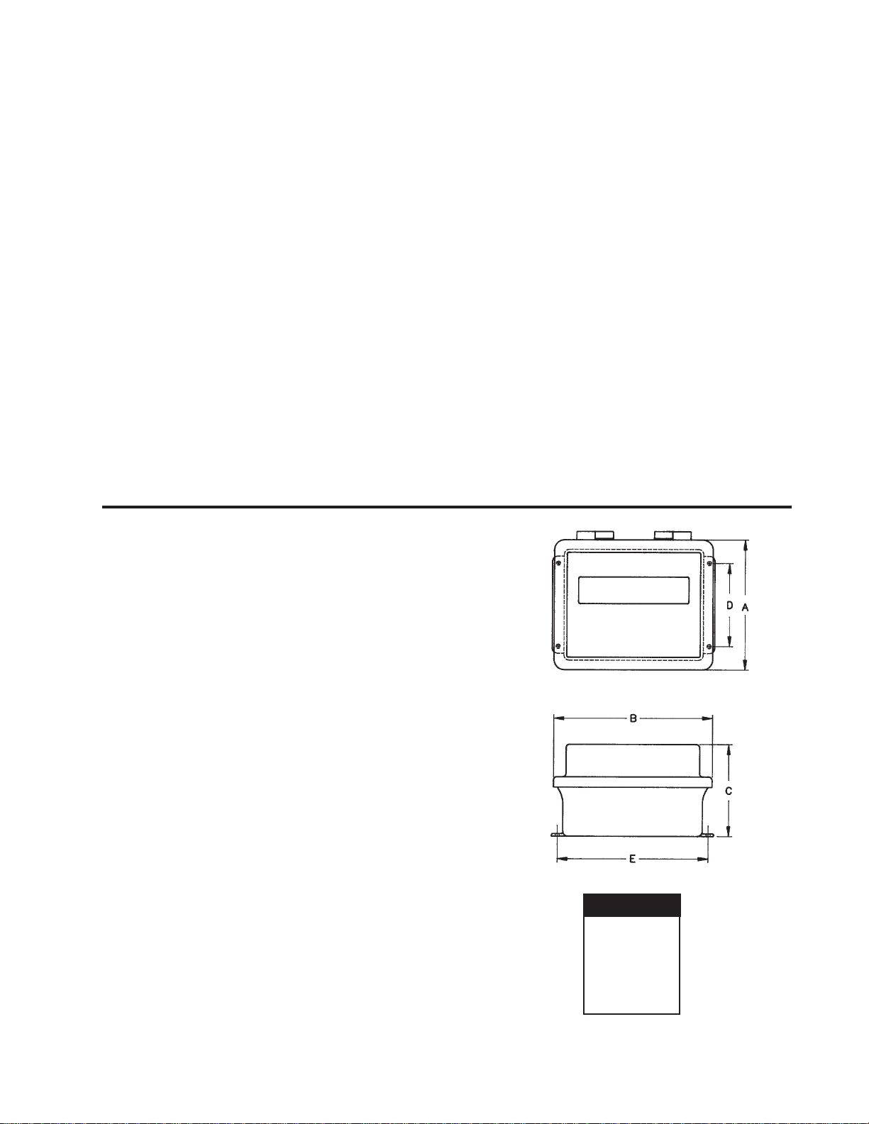
Dimensions
A= 9.38"
B=11.38"
C= 6.63"
D= 6.00"
E=10.81"
10/96
1
Page 3
2. Serial Communications Connections
GROUND
SIGNAL IN
GROUND
TX
DATA
RX
DATA
+XMIT
CL RETURN
-XMIT
CL DATA
+RECEIVE
CL DATA
-RECEIVE
CL RETURN
V+
0
N
∆
1 2 3 4 5 6 7 8
J1
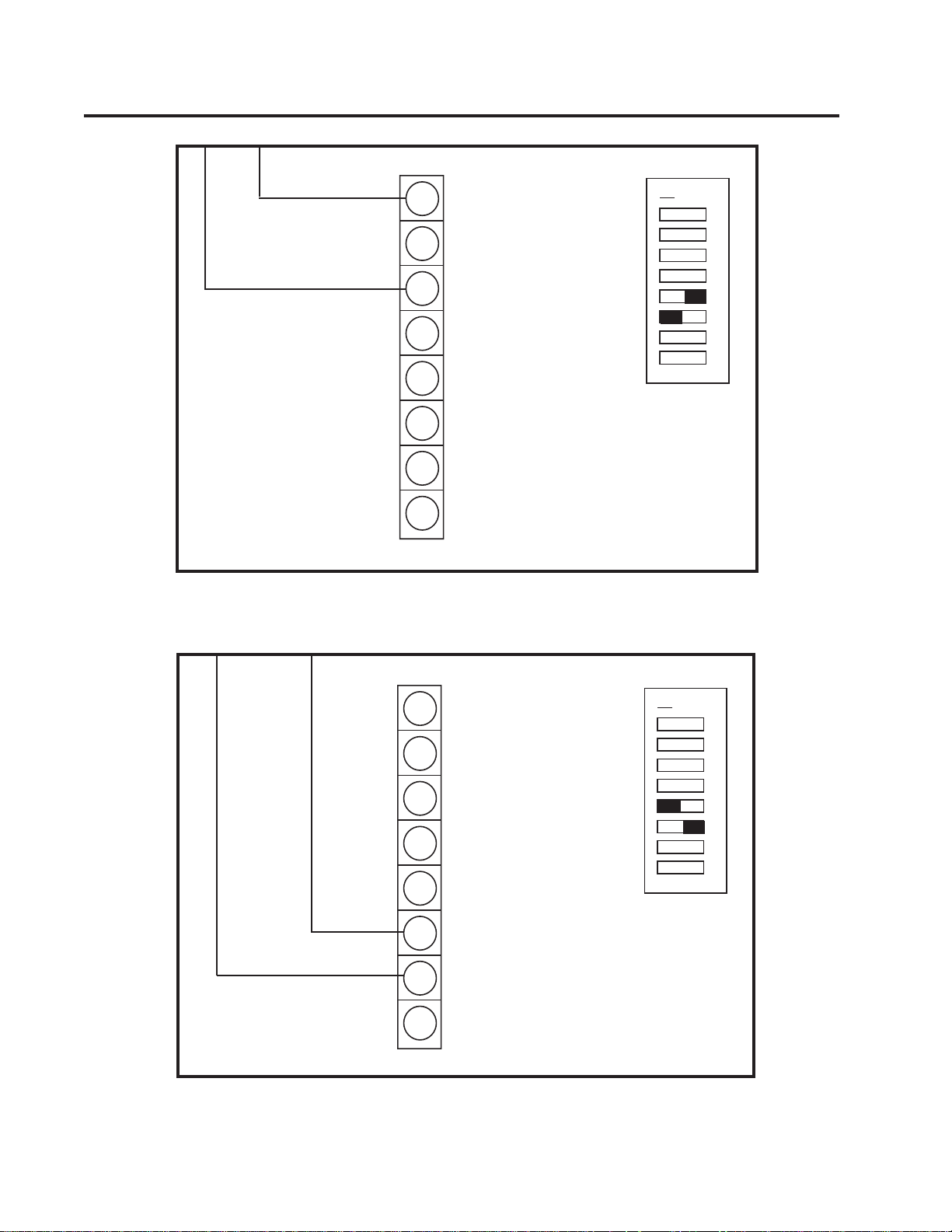
Communications Connections: RS-232C
GROUND
TX
DATA
RX
DATA
+XMIT
CL RETURN
-XMIT
CL DATA
20 mA +
+RECEIVE
CL DATA
20 mA -
-RECEIVE
CL RETURN
0
N
∆
1 2 3 4 5 6 7 8
V+
J1
Communications Connections: 20 mA Current Loop Passive
2
Page 4

GROUND
TX
DATA
RX
DATA
+20 mA
+XMIT
CL RETURN
-XMIT
CL DATA
–20 mA
+RECEIVE
CL DATA
-RECEIVE
CL RETURN
V+
J1
Communications Connections: 20 mA Current Loop Active
0
N
∆
1 2 3 4 5 6 7 8
3
Page 5

3. Configuration of Dip Switches
The purpose of dip switches #1-#6 is to ensure that the remote display and the indicator
are communicating in the same format. Consult your indicator manual to find the indicator's
current configuration. Check that the correct EPROM has been installed. Disconnect power
and set switches 1-6. Switches #7 and #8 enable the time and temperature display if those
options are installed.
Switch #1--Data Transfer Rate
(F 1.5 Series EPROM Version) (Series 1, 2, or 3 EPROM Version)
off 1200 BAUD off 300 BAUD
on 2400 BAUD on 1200 BAUD
Switch #2--Number of Data Bits
off 7 data bits
on 8 data bits
Switch #3--Number of Stop Bits
off 1 stop bit
on 2 stop bits
Switch #4--Odd Parity
off no parity or parity disabled
on odd / even parity enabled
Switch #5 and #6--Serial Input Format
5 off 6 on 20 mA Current Loop
5 on 6 off RS232C
Switch #7--Time Display (Unavailable Option)
off time display disabled
on time display enabled
Switch #8--Temperature Display (Unavailalble Option)
off temperature display disabled
on temperature display enabled
4
Page 6

4. Troubleshooting Guide
PROBLEM SOLUTION
A. No display check at power-up. Replace fuse (1/4 A Slo-Blo).
Check AC receptacle for proper 120V
power supply.
Press reset switch on circuit board.
B. Display shows no or different data than Check that serial communication lines
indicator. are connected properly.
Check that the indicator and remote display
are configured in the same format.
Display has incorrect program for indicator
(see Sec. 5).
5
Page 7

5. Remote Display / Indicator Programs
Program # Indicator and Operating Mode
F1_5-1D UMC1000, UMC2000, IQ600, IQ700 — Continuous
F1_5-1D Thurman EDS4 - EPROM in indicator is Continuous Condec format
F1_5-2B UMC 1000, 2000 — Demand
F1_5-3B Toledo 8140, 8142, 8530, 81321, 9481 — Continuous
F1_5-3B Fairbanks 9201RS-232 (Use COM port 1 only)
F1_5-4D IQplus 800/810, IQplus 310 Continuous (End of line set to CR/LF)
F1_5-5A StreeterAmet 9000 — Continuous
F1_5-6A Cardinal 738 — Continuous
F1_5-7A Western DF1000 — Continuous
F1_5-8A Pennsylvania 5600 — Continuous
F1_5-9A Flexweigh DWM IV — Continuous
F1_5-10A IDS print w/BCD to 20 mA conversion — Continuous
F1_5-11A AD 4321 — Continuous (Format 1, display will not show negative sign)
F1_5-12A IQ700 Truck ID for KBB 8-1, Ver. EF EPROM
F1_5-13A Analogic 5316 — Continuous, HB 44 (EPROM 13.0 shows gross only)
F1_5-14A Electroscale 533 — Continuous
F1_5-15A IQ700, IQplus 310 Demand (Net or Gross) with Time and Date
F1_5-16A WI-110, WI-120, WI-130 — Continuous
F1_5-17A Toledo 8142 with BCD Converter
F1_5-18A Doran 7000 — Continuous
F1_5-19A Fairbanks 90-164-1, 90-166-1, 9201 (out Com 2) — Continuous (20 mA passive only)
F1_5-1C UMC 1000, UMC 2000, IQ600, IQ700 — Continuous
F1_5-21A Electroscale 551 — Continuous
F1_5-22A Analogic 5316, EPROM Revision 13.0.9 — Continuous
F1_5-23A General Freedom I and II — Continuous
F1_5-24A ACCU-WEIGH SEP-12K, Format 8 — Continuous
F1_5-25A Kubota KA-10 — Continuous
F1_5-26A Flexweigh DWMIV Continuous w/Post & Preamble (02H, 03H)
F1_5-27A MSI TRANS-WEIGH — Continuous
F1_5-28A OHAUS 1150 — Continuous
F1_5-29A Hardy HI 2151 WC — Continuous
F1_5-30A Pennsylvania 3100 — Continuous
F1_5-31A IQplus 800/810 — Demand (Standard default format)
F1_5-32A IQplus 310 — Demand (Net Weight Only)
F1_5-33A IQplus 310 — Demand (Gross Weight Only)
F1_5-34A Fairbanks 90-163-1 — Continuous
F1_5-36A IQ700, IQplus 310, — Demand (Net or Gross) with Time and Date
F1_5-37A Tyrel TC-10 / Howe-Richardson HR500k Continuous
F1_5-38A Tara TR-1 Continuous, 1200 baud, fixed 8 bits, no parity, 2 stop bits
F1_5-39A Allegany Mega 8—Continuous
F1_5-40A A-N-D FG Bench Scale
F1_5-41A Cardinal 748 — Continuous
F1_5-42A 3-weight 810 — Continuous
3
4
2
Notes:
1 The Toledo 8132 meter will not work with the 234HE without special programming to operate the 234HE at 4800 baud.
2 The WI130 indicator must be programmed to stream out in the standard Weightronix format to use the WI110/WI120 flip digit driver.
3 The Allegany Mega 8 sends out eight weight display digits. The EL234HE Remote Display shows the least significant six digits.
4 This special format contains three weight strings within one serial string. Dip switches 7 and 8 in switchbank 2 control which of the three
strings are displayed as follows:
2-7 2-8 String Displayed
off off 1st
off on 2nd
on off 3rd
6
Page 8

6. Replacement Parts for 234HE 1.5" Flip Digit Display
DESCRIPTION PART NUMBER
1.5" Display, CPU Board................................................................... 21024
1.5" Display, Mounting Board............................................................ 21025
Enclosure, Fiberglass Reinforced Polyester ..................................... 16019
Back Panel ........................................................................................ 16084
EPROM, F1.5-XXX (programmed as required)................................. 16246
Cord Grip Assembly for Power Cord, 1/2" NPT ................................ 15671
Desiccant, 5 Gram Package .............................................................16038
Power Cord Pigtail ............................................................................15436
Lexan Window, 9 X 4 3/4 .................................................................. 16083
“High Voltage” Warning Label for Lexan Shield ................................ 16861
16 Pin Connector ..............................................................................15823
Fuse, 1/4A SLO-BLO ........................................................................ 16444
Fuse Holder, Single Pole ..................................................................16771
Fuse Cover........................................................................................ 16772
Installation Manual, 243HE Remote Display..................................... 16945
7
Page 9

7. 234HE Limited Warranty
Rice Lake Weighing Systems (RLWS) warrants that all RLWS equipment and systems properly installed by a
Distributor or Original Equipment Manufacturer (OEM) will operate per written specifications as confirmed
by the Distributor/OEM and accepted by RLWS. All systems and components are warranted against defects
in materials and workmanship for one (1) year.
RLWS warrants that the equipment sold hereunder will conform to the current written specifications authorized by RLWS. RLWS warrants the equipment against faulty workmanship and defective materials. If any
equipment fails to conform to these warranties, RLWS will, at its option, repair or replace such goods returned within the warranty period subject to the following conditions:
1. Upon discovery by Buyer of such non-conformity, RLWS will be given prompt written notice with a detailed explanation
of the alleged deficiencies.
2. Individual electronic components returned to RLWS for warranty purposes must be packaged to prevent electrostatic
discharge (ESD) damage in shipment. Packaging requirements are listed in a publication, “Protecting Your Components
From Static Damage in Shipment,” available from RLWS Equipment Return Department.
3. Examination of such equipment by RLWS confirms that the non-conformity actually exists, and was not caused by
accident, misuse, neglect, alteration, improper installation, improper repair or improper testing; RLWS shall be the sole
judge of all alleged non-conformities.
4. Such equipment has not been modified, altered, or changed by any person other than RLWS or its duly authorized repair
agents.
5. RLWS will have a reasonable time to repair or replace the defective equipment. Buyer is responsible for shipping charges
both ways.
6. In no event will RLWS be responsible for travel time or on-location repairs, including assembly or disassembly of
equipment, nor will RLWS be liable for the cost of any repairs made by others.
THESE WARRANTIES EXCLUDE ALL OTHER WARRANTIES, EXPRESSED OR IMPLIED,
INCLUDING WITHOUT LIMITATION WARRANTIES OF MERCHANTABILITY OR FITNESS
FOR A PARTICULAR PURPOSE. NEITHER RLWS NOR DISTRIBUTOR WILL, IN ANY EVENT,
BE LIABLE FOR INCIDENTAL OR CONSEQUENTIAL DAMAGES.
RLWS AND BUYER AGREE THAT RLSW’S SOLE AND EXCLUSIVE LIABILITY HEREUNDER
IS LIMITED TO REPAIR OR REPLACEMENT OF SUCH GOODS. IN ACCEPTING THIS WARRANTY, THE BUYER WAIVES ANY AND ALL OTHER CLAIMS TO WARRANTY.
SHOULD THE SELLER BE OTHER THAN RLWS, THE BUYER AGREES TO LOOK ONLY TO
THE SELLER FOR WARRANTY CLAIMS.
No terms, conditions, understanding, or agreements purporting to modify the terms of this warranty shall have any legal effect unless
made in writing and signed by a corporate officer of RLWS and the Buyer.
© 1996 Rice Lake Weighing Systems, Inc. Rice Lake, WI USA. All Rights Reserved.
RICE LAKE WEIGHING SYSTEMS
Tel: 715-234-9171 Service Hotline: 715-234-2003 Fax: 715-234-6967
• 230 WEST COLEMAN STREET • RICE LAKE, WISCONSIN 54868 • USA
8
 Loading...