

Page 1
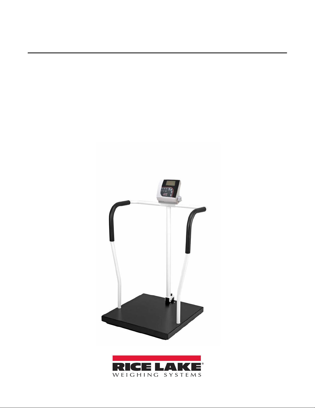
Digital Handrail Scale
Model 260-10-1
Software Version 11454
Operation Manual
PN 172479
Page 2

Page 3

Contents
1.0 Introduction.................................................................................................................................. 1
1.1 Safety Symbol Definitions . . . . . . . . . . . . . . . . . . . . . . . . . . . . . . . . . . . . . . . . . . . . . . . . . . . . . . . . 1
2.0 Assembly...................................................................................................................................... 2
2.1 Unpacking the Scale . . . . . . . . . . . . . . . . . . . . . . . . . . . . . . . . . . . . . . . . . . . . . . . . . . . . . . . . . . . . 2
2.1.1 Repackaging the Scale . . . . . . . . . . . . . . . . . . . . . . . . . . . . . . . . . . . . . . . . . . . . . . . . . . . . . . . . . . . . . 2
2.2 Setting Up the Scale . . . . . . . . . . . . . . . . . . . . . . . . . . . . . . . . . . . . . . . . . . . . . . . . . . . . . . . . . . . . 2
2.3 Inserting Batteries . . . . . . . . . . . . . . . . . . . . . . . . . . . . . . . . . . . . . . . . . . . . . . . . . . . . . . . . . . . . . . 5
2.4 AC Power Connections . . . . . . . . . . . . . . . . . . . . . . . . . . . . . . . . . . . . . . . . . . . . . . . . . . . . . . . . . . 5
3.0 Operation...................................................................................................................................... 6
3.1 Key Description . . . . . . . . . . . . . . . . . . . . . . . . . . . . . . . . . . . . . . . . . . . . . . . . . . . . . . . . . . . . . . . . 6
3.2 Weighing . . . . . . . . . . . . . . . . . . . . . . . . . . . . . . . . . . . . . . . . . . . . . . . . . . . . . . . . . . . . . . . . . . . . . 7
3.3 Hold Release . . . . . . . . . . . . . . . . . . . . . . . . . . . . . . . . . . . . . . . . . . . . . . . . . . . . . . . . . . . . . . . . . . 7
3.4 Preset Tare. . . . . . . . . . . . . . . . . . . . . . . . . . . . . . . . . . . . . . . . . . . . . . . . . . . . . . . . . . . . . . . . . . . . 7
3.5 Toggle Tare . . . . . . . . . . . . . . . . . . . . . . . . . . . . . . . . . . . . . . . . . . . . . . . . . . . . . . . . . . . . . . . . . . . 8
3.6 Body Mass Index (BMI) . . . . . . . . . . . . . . . . . . . . . . . . . . . . . . . . . . . . . . . . . . . . . . . . . . . . . . . . . . 8
3.6.1 LB Mode. . . . . . . . . . . . . . . . . . . . . . . . . . . . . . . . . . . . . . . . . . . . . . . . . . . . . . . . . . . . . . . . . . . . . . . . 8
3.6.2 KG Mode . . . . . . . . . . . . . . . . . . . . . . . . . . . . . . . . . . . . . . . . . . . . . . . . . . . . . . . . . . . . . . . . . . . . . . . 8
4.0 Communication............................................................................................................................ 9
4.1 Pushbutton Keypad Print . . . . . . . . . . . . . . . . . . . . . . . . . . . . . . . . . . . . . . . . . . . . . . . . . . . . . . . . 9
4.2 USB Connection . . . . . . . . . . . . . . . . . . . . . . . . . . . . . . . . . . . . . . . . . . . . . . . . . . . . . . . . . . . . . . 10
5.0 Maintenance .............................................................................................................................. 12
5.1 Basic Maintenance . . . . . . . . . . . . . . . . . . . . . . . . . . . . . . . . . . . . . . . . . . . . . . . . . . . . . . . . . . . . 12
5.2 Cleaning . . . . . . . . . . . . . . . . . . . . . . . . . . . . . . . . . . . . . . . . . . . . . . . . . . . . . . . . . . . . . . . . . . . . . 12
6.0 Troubleshooting ......................................................................................................................... 13
7.0 Specifications............................................................................................................................ 14
© Rice Lake Weighing Systems. All rights reserved. Printed in the United States of America.
Specifications subject to change without notice.
Rice Lake Weighing Systems is an ISO 9001 registered company.
Version 11454 February 18, 2016
Contents i
Page 4

ii Rice Lake 260 Digital Handrail Scale
Page 5
1.0 Introduction
WARNING
CAUTION
Important
WARNING
Important
The Rice Lake 260-10-1 Digital Handrail Scale is efficiently designed to provide accurate, reliable and repeatable
weight measurements. A non-skid platform paired with side rails assists individuals needing extra support for
safety reasons. The weight is displayed on the indicator in pounds or kilograms.
1.1 Safety Symbol Definitions
Indicates a potentially hazardous situation that, if not avoided, could result in death or serious injury, and
includes hazards that are exposed when guards are removed.
Indicates a potentially hazardous situation that, if not avoided, may result in minor or moderate injury.
Indicates information about procedures that, if not observed, could result in damage to equipment or
corruption to and loss of data.
General Safety
Do not operate or work on this equipment unless you have read and understand the instructions and
warnings in this Manual. Contact any Rice Lake Weighing Systems dealer for replacement manuals.
Proper care is your responsibility.
Failure to heed may result in serious injury or death.
Ensure every individual who operates or works with this unit has read and understands the following safely information.
Do not transport the scale while someone is standing on it.
Do not allow minors (children) or inexperienced persons to operate this scale.
People with disabilities, or who are physically frail, should always be assisted by another person when using this scale.
Do not use the scale on slippery surfaces, such as a wet floor.
Do not use this scale when a person’s body or feet are wet, such as after taking a bath.
Do not jump on the scale.
To avoid cross contamination, the scale should be cleaned regularly.
Prior to cleaning, make sure the scale is disconnected from the power source.
Do not use near water.
Do not drop the scale or subject it to violent shocks.
Do not use this product if any of the components are loose or cracked.
Do not use in the presence of flammable materials.
For accurate weighing, the scale must be placed on a flat, stable surface.
Weight exceeding the maximum capacity (800 lb/360 kg) may damage the scale.
Operating at voltages and frequencies other than specified could damage the equipment.
Avoid contact with excessive moisture.
Rice Lake Weighing Systems offers optional AC adapters; utilizing an adapter not supplied by RLWS voids all warranties
and approvals.
Do not make alterations or modifications to the scale.
Introduction 1
Page 6
2.0 Assembly
Important
Important
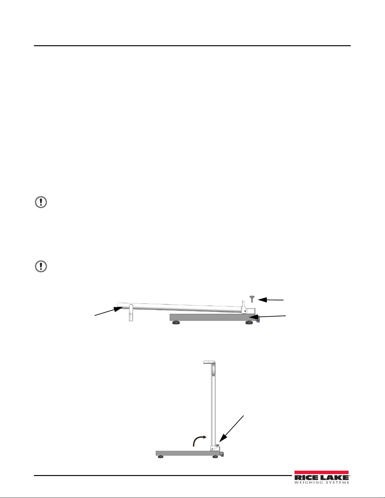
Handrail center post
Screw knob
Scale base
Secure
screw knob
2.1 Unpacking the Scale
A minimum of two people should transport, unpack and assemble the scale for their own personal safety and to
ensure the integrity of the scale. Use caution while removing packaging and unpacking the scale. After unpacking,
visually inspect the Rice Lake 260-10-1 Digital Handrail Scale to ensure all components are included and
undamaged. Contact Rice Lake Weighing Systems and the shipper immediately if the scale was damaged during
shipping.
Parts contained in the shipping box include:
• Scale platform with handrail center post
• Indicator
• Handrails
• Parts kit including hardware for assembly
• Six AA non-rechargeable batteries
2.1.1 Repackaging the Scale
If the Rice Lake 260-10-1 Digital Handrail Scale must be returned for modification or repair, it must be properly
packed with sufficient packing materials. Whenever possible, use the original carton when shipping the scale back.
Damage caused by improper packaging is not covered by the warranty.
2.2 Setting Up the Scale
Move the scale into the area where the weighing process will occur. Place the scale on a hard, level surface for the
most accurate weighments. A 3/8 inch socket wrench (or equivalent) and a Phillips screwdriver are required for
assembly.
1. A minimum of two people should carefully remove the scale by lifting it out of the box by the scale base.
Do not lift the scale out of the box by the handrail post as this may cause damage.
2. Place the scale on the floor or other hard level surface.
3. Remove the screw knob at the base of the ha
Figure 2-1. Scale in Shipping Position
ndrail center post.
4. Lift the handrail center post until it is perpendicular to the base.
5. Insert and tighten the screw knob on the base until the handrail center post is rigid and does not move.
2 Rice Lake 260-10-1 Digital Handrail Scale
Figure 2-2. Scale in Upright Position
Page 7

6. Roll back the rubber grip from each handle.
Rubber
Grip
Handrail center post
Indicator Bracket
Right Handrail
5x16 mm
Screws
(incl. in parts kit)
Right Handrail
Figure 2-3. Scale Handrail
7. Insert the handles into the handrail post (Fig. 2-4).
Figure 2-4. Handrail to Post Assembly
The right handrail is denoted by a red dot sticker on the base end of the handrail (Fig. 2-5). This sticker
may be removed after assembly.
Figure 2-5. Right Handrail Designation
8. Insert the screws and tighten with a Phillips screwdriver to secure the handles to the handrail base.
Roll the rubber grips back into position.
9.
Figure 2-6. Rubber Grips in Proper Position
Assembly 3
Page 8

10. Gently tip the scale and lay it down so that the handrail center post is touching the floor.
3/8 x 1½ inch Bolts
and Washers
(incl. in parts kit)
Indicator
Bracket
¼ x 3/8 inch Screws
and Washers
(incl. in parts kit)
Load Cell
Connection Port
Screws
Back Cover
11. Insert the bolts and washers, in the order shown, from underneath the platform and
hten with a 3/8 inch socket wrench
Tig
Figure 2-7. Handrail to Base Assembly
.
into the handrails.
12. Secure the indicator to the handrail center post by inserting two screws and washers, in the order shown,
from
the top plate of the indicator and through the
Tighten with a Phillips screwdriver.
13.
bracket.
Figure 2-8. Indicator Assembly
14. Remove the four screws securing the back cover to the indicator with a Phillips screwdriver.
15. Connect the cable to the indicator by plugging it into the load cell connection port.
16. Replace the back cover of the indicator and the four screws and secure with a Phillips screwdriver.
4 Rice Lake 260-10-1 Digital Handrail Scale
Figure 2-9. Indicator to Load Cell Cable Connection
Page 9

2.3 Inserting Batteries
Note
Important
Optional AC
power source
connection
The six AA non-rechargeable batteries that come with the scale offer an average of 25 hours of continuous use.
To install the batteries:
1. Open the battery chamber cover by loosening the thumbscrew.
2. Insert batteries into the battery chamber. Ensure that the batteries are aligned according to the diagram
the battery
3. Close the battery chamber.
If an external power supply is connected, the battery flag on the display is turned off.
When using a battery power supply, the brightness of the backlight is reduced to 60 percent.
chamber.
Figure 2-10. Battery Chamber
in
2.4 AC Power Connections
Rice Lake Weighing Systems offers optional 120 VAC or 230 VAC adapters to use when power is available. The
optional AC power adapter plugs into the back of the indicator as shown in Figure 2-11.
The indicator does not contain a recharge circuit and will not recharge batteries of any kind.
Utilizing an adapter not supplied by Rice Lake Weighing Systems voids all warranties and approvals.
Figure 2-11. Optional AC Power Connection
Assembly 5
Page 10

3.0 Operation
BMI
TARE
T
CLEAR
ENTER
The Rice Lake 260-10-1 Digital Handrail Scale has the capability of performing operations beyond just calculating
weight. The following describes the various operating keys and instructions for operating the scale.
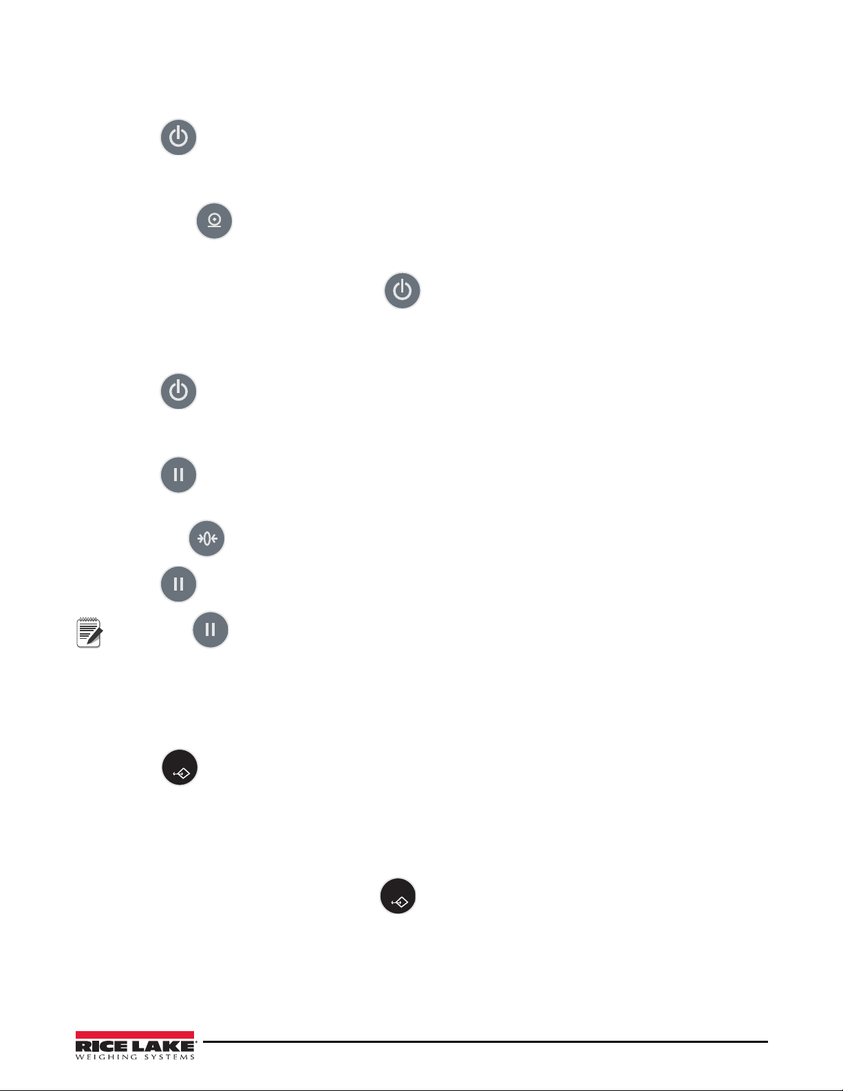
3.1 Key Description
The Rice Lake 260-10-1 Digital Handrail Scale has ten front panel keys.
Figure 3-1. Front Panel Key Display
Key Key Name Function
On/Off The power key switches the scale on or off.
Print
LB/KG
Zero The Zero key clears the weight off the scale and returns the scale to zero after three
Hold Release Hold Release — The first press holds the most current weight value shown on the display.
BMI The BMI key enables the user to access the BMI (Body Mass Index) function. This key
TARE Used to subtract the weight of additional items off the scale.
CLEAR Allows the user to return to normal weighing when the BMI value is being displayed.
ENTER Used to accept height in BMI mode. Accepts the value of an entered parameter and
Up/Down Arrows The Up/Down arrows are sued to adjust height input (0.5 in/0.5 cm) while in BMI mode
Print — A long key press will send data out from the RS-232 port.
LB/KG — A short key press allows the user to toggle between kilograms and pounds,
providing that it’s enabled in configuration mode. Toggling between pounds and
kilograms is not available in the BMI mode. The BMI will be calculated according to the
unit selectd prior to entering the BMI mode.
seconds.
the zero function works only if the current weight is stable and will zero up to 2 percent of
full weight.
A second press releases the weight value shown.
This key is not active while in BMI mode.
works only if there is a locked weight shown on the display and the BMI function is turned
on in the setup mode.
Example: blankets, oxygen units, and other equipment.
moves to the next stage. A long press of the ENTER key during the scale’s start up
process will enter the ID display (pre-parameter mode).
and to enter a toggle tare value.
The Up/Down arrows adjust the value of the flashing digit/number.
Table 3-1. Front Panel Keys and Functions
6 Rice Lake 260-10-1 Digital Handrail Scale
Page 11
3.2 Weighing
Note
TARE
T
TARE
T
Use the following steps to weigh a person.
1. Press to turn the scale on. The display shows
0.0 and the ZERO annunciator is on.
2. Have the person step on the scale. The display shows the person’s weight, the
the
indicator beeps to indicate the end of the weighing process.
3. Short press to toggle the display from kg to lb, if desired.
4. Have the person step off the scale. The display returns to
5. Turn the scale off by pressing and
holding
until
0.0 and the ZERO annunciator is on.
OFF displays.
3.3 Hold Release
Use the following steps to perform the Hold Release function.
1. Press to turn the scale on. The display shows
2. Have the person step on the scale. The display shows the person’s weight, the
the
indicator beeps to indicate the end of the weighing process.
3. Press .
4. Have the person step off the scale. The display shows the person’s weight and the
0.0 and the ZERO annunciator is on.
LOCK annunciator is on and
LOCK annunciator is on, and
HOLD LOCK annunciator
The will not work at this stage.
is on.
5.
Press
Pressing prior to a person getting on the scale will also hold the weight display.
to return to zero. The display shows
0.0 and the ZERO annunciator is on.
3.4 Preset Tare
Use the following steps to perform a Preset Tare.
1. With the weight at
units, and other equipment) on the scale. Wait for the weight to stabilize.
2. Press
3. Remove the additional items from the scale. The display will show the weight with a
the
left of it and the
4. Have the person step on the scale with the additional items. The display shows the person’s weight, the
annunciator remains on, and
5.
To cancel the tare weight, press and
returns to
0.0 and the GROSS annunciator displays. Alternatively, tare weight is canceled when the scale is
turned off.
0.0 and the ZERO annunciator on, place the additional items (such as blankets, oxygen
until the display returns to
0.0 and the NET annunciator is on.
negative symbol to
NET annunciator remains on.
the weight of the additional items remains stored in memory.
hold until the
NET annunciator no longer displays, the weight
NET
Operation 7
Page 12

3.5 Toggle Tare
TARE
T
ENTER
TARE
T
BMI
ENTER
CLEAR
BMI
ENTER
CLEAR
Toggle tare is used to set a tare value when the weight of the additional items (such as blankets, oxygen units, and
other equipment) is known. Use the following steps to perform a Toggle Tare.
1. With the weight at 0.0 and the
ZERO annunciator on, press . The default tare value (33.0 lb/15.0 kg)
is displayed with the last digit flashing.
2.
Press
and/or to adjust the value.
3. Press to accept the entered value and start the tare function. The display will show the weight with a
negative symbol to the left of it and the
NET annunciator will display.
4. Have the person step on the scale with the additional items. The display shows the person’s weight, the
annunciator remains on, and
5. To cancel the toggle tare weight, press and hold until the
weight returns to
0.0 and the GROSS annunciator displays. Alternatively, the toggle tare weight is canceled
the weight of the additional items remains stored in memory.
NET annunciator is no longer displayed, the
when the scale is turned off.
3.6 Body Mass Index (BMI)
Use the following steps in determining BMI.
3.6.1 LB Mode
1. With the weight at 0.0 and the ZERO annunciator on, have the person step on the scale. The display shows
the person’s weight, the LOCK annunciator is on and the indicator beeps to indicate the end of the weighing
process.
NET
2. Press . The
(
5-07.5) is flashing.
3.
Press
4.
Press
5.
Press
BMI and FT/IN annunciators display and a default height value of 5 feet and 7.5 inches
and/or to adjust the height value.
. The display shows the BMI value and the
BMI annunciator is on.
to return to the weighing mode and turn off the BMI function.
3.6.2 KG Mode
1. With the weight at 0.0 and the ZERO annunciator on, have the person step on the scale.The display shows
the person’s weight, the LOCK annunciator is on and the indicator beeps to indicate the end of the weighing
proce
ss.
2. Press . The
flashing in the display.
Press
3.
Press
4.
BMI and FT/IN annunciators are displayed. The default height value of 170.0 cm (170.0) is
and/or to adjust the height value.
. The display shows the BMI value and the
BMI annunciator is on.
5.
Press
8 Rice Lake 260-10-1 Digital Handrail Scale
to return to the weighing mode and turn off the BMI function.
Page 13

4.0 Communication
Note
The Rice Lake 260-10-1 Digital Handrail Scale comes with an RS-232 port which enables weight data to be
transmitted to other equipment, such as a computer or printer. The RS-232 cable with DB-9 connector (PN 100719)
is available from Rice Lake Weighing Systems. Figure 4-1 shows where the RS-232 connection is located on the
indicator.
The RS-232 parameters are 9600 baud (selectable in the programming mode), 8 data bits, 1 stop bit, no parity and
no handshaking.
There are three methods of communication:
• Pushbutton keypad print
• Standard remote protocol
• Escape protocol
4.1 Pushbutton Keypad Print
With a stable, in-range weight, press and hold for at least three seconds, or until the scale emits two quick
beeps.
If the scale does not beep after five seconds, release the button as the weight was either in motion, or out of
range.
In weighing mode, the scale will send out the 21 character string: xxxxxxxxx<SP>uu<SP>mmmmm<SP><CR><LF>
Where:
xxxxxxxxx is the weight with decimal point and " - " sign, if negative
uu is the unit (lb or kg)
mmmmm is the mode (gross or net)
Examples:
-10 Lb net = <SP><SP><SP><SP>-10.0<SP>lb<SP><SP>Net<SP><SP><SP><CR><LF>
10 Lb gross = <SP><SP><SP><SP><SP>-10.0<SP>lb<SP>Gross<SP><CR><LF>
Example: in BMI mode (displaying the BMI value), the scale will send out the following data:
GROSS WEIGHT 215.0 LB
TARE WEIGHT 0.0 LB
NET WEIGHT 215.0 LB
PATIENT HEIGHT 6-01.0 FT
PATIENT BMI 28.4
Communication 9
Page 14

4.2 USB Connection
USB Connection
RS-232 Connection
The Rice Lake 260-10-1 Digital Handrail Scale has the capability of connecting to a PC using a USB connection
and a USB cable (not included). The USB cable location is shown in Figure 4-1.
Figure 4-1. USB and RS-232 Connection Ports
Connecting software and downloads should be addressed by an IT professional, and can vary depending on what
®1
type of computer platform is being used. Basic information on USB driver installation using Windows
described in the following steps and serves only as an example.
A USB driver can be downloaded from the Rice Lake Weighing Systems website at:
http://www.ricelake.com/software.aspx
1. From the drop down menus select:
Medical/Health Scales, Software, All Languages (or select desired
language), then click on Get Downloads.
is
Figure 4-2. Software Download Page
2. Select any product by clicking the > next to the product name and a USB Driver download will display.
. Click on
3
Figure 4-3 shows the window that pops up when the USB cable is connected to
4.
is turned
Download to open and download the driver to a local computer.
on. Follow the screen prompts to navigate through the software install pr
Figure 4-3. Hardware Wizard Screen
the indicator and the scale
ocess.
1. Microsoft, Encarta, MSN, and Wind ows are either registered trademarks or trademarks of Microsoft Corporation
in
the United States and/or other countries.
10 Rice Lake 260-10-1 Digital Handrail Scale
Page 15

5. Select No, not this time, and then select Next.
Important
6. Select
Install the software automatically, then select Next. A file transfer screen will display as the file
downloads and installs to the computer.
7.
Click on
Finish when the completion screen displays.
8. To verify the installation, the driver can be viewed in the device manager of the computer.
Figure 4-4. Device Manager
9. To configure a printer using the USB driver, open the software driver Parpar in the device manager
(Figure 4-4). The port assigned to that driver is displayed.
10. Ensure that the USB cable is properly connected and the unit is on.
11. Another terminal type program (such as Hyperterminal) must be opened and connected through
driver to the
tha
t is assigned to
indicator to see the information being transmitted to the PC. To establish a port, select
Parpar.
the USB
the port
12. P
ress
. The following example tickets will print.
Figure 4-5. Example Tickets
A single print ticket has four spaces after PATIENT WEIGHT and only one space between weight and lb in the
examples shown above. Then seven <CR><LF> after.
Figure 4-6. IT Example Ticket
Figure 4-6 is for IT information only. The tickets print as in Figure 4-5.
Communication 11
Page 16

5.0 Maintenance
5.1 Basic Maintenance
Before the first use of the scale, and after periods of non-use, check the scale for proper operation and function. If
the scale does not operate correctly, contact qualified service personnel.
Perform the following steps for basic maintenance.
1. Check the overall appearance of the entire scale for any obvious signs of damage.
2. Inspect the condition of the AC adapter for a cracking or fraying cord, as well as for broken or bent prongs.
5.2 Cleaning
Proper care and cleaning of the scale is essential to extend the life of the scale and to ensure accurate operation.
Before beginning the cleaning process, disconnect the scale from the AC power source.
1. Clean all external surfaces with a soft, clean, damp cloth or tissue. A mild soap and water solution ma
used.
2.
Dry with a clean, soft cloth.
3. Do not immerse the scale into cleaning or other liquid solutions.
4. Do not use isopropyl alcohol or other solvents to clean the display surface.
y be
12 Rice Lake 260-10-1 Digital Handrail Scale
Page 17

6.0 Troubleshooting
Refer to the following to check and correct any errors. Contact Customer Service personnel if the issue persists.
Symptom Possible Cause Corrective Action
The scale does not turn on. The batteries are dead. Install new batteries or connect the scale to a
power source.
The electrical outlet is faulty. Plug the scale into a different electrical outlet.
The AC power adapter is bad. Replace the optional AC power adapter.
The weight is questionable or
the scale does not zero.
The indicator displays a STOP
message.
The indicator displays a LO Bat
message.
An external object is interfering with the
scale.
The scale was not at zero prior to
weighing.
The scale is not placed on a level floor. Ensure the scale is level and begin the weighing
The scale is out of calibration. Check the scale with a known weight value.
The load on the scale exceeds the
capacity of the scale.
The battery power is low. Install new batteries or connect the scale to a
Remove the interfering object from the scale.
Help the patient off the scale, zero the scale and
begin the weighing process again.
process again.
Recalibrate the scale.
Help the patient off the scale and remove any
additional items. Use the scale accrording to
manufacture’s specifications. See Section 7.0 on
page 14.
power source.
The indicator displays any of the following Err messages.
Err 2 A low saturation state (low A/D) exists.
The load cell is not connected properly.
Err 3 A high saturation state (high A/D) exists.
The load cell is not connected properly.
Err 6 The weight is unstable and calibration
does not work.
Table 6-1. Troubleshooting Table for the Rice Lake 260-10-1 Digital Handrail Scale
The load cell is not connected properly. Check
the cables and mechanical connections. If the
problem persists, replace the set of load cells.
The load cell is not connected properly. Check
the cables and mechanical connections. If the
problem persists, replace the set of load cells.
Check the load cells’ mechanical surroundings
and see that nothing touches them and that the
cables are properly welded.
Troubleshooting 13
Page 18

7.0 Specifications
Power
Optional AC Adapter - 120 VAC-9VDC-60Hz or 230 VAC
Battery Type
6 AA size non-rechargeable alkaline batteries
Battery Use
25 hours continuous use
Automatic power-off can be configured
Data Communications
RS-232 with RJ-45 jack
USB connection
Selectable baud rate, default - 9600
8 bits
No parity
1 stop bit
No handshaking
Environmental
Operating Temperature
50°F to 104°F (10°C to 40°C)
Storage Temperature
32°F to 158°F (0°C to 70°C)
Humidity
85% relative humidity
Capacity and Graduation
800 lb (360 kg) 0.2 lb (100 g)
Dimensions
Platform Dimensions
23½ in W x 23½ in L x 2¾ in H
Height
33½ in
Height with Height Rod (optional)
87½ in
Certifications and Approvals
RoHS Compliant
14 Rice Lake 260-10-1 Digital Handrail Scale
Page 19

Page 20

2/18/16 PN 172479
© Rice Lake W
eighing Systems Specifications subject to change without notice.
 Loading...