

Page 1
SURVIVOR® 1700HE
Weigh Module Kit
Installation
33318 Rev A
Page 2

Page 3

Technical training seminars are available through Rice Lake Weighing Systems.
Course descriptions and dates can be viewed at www.ricelake.com/training
or obtained by calling 715-234-9171 and asking for the training department.
Contents
1.0 Introduction . . . . . . . . . . . . . . . . . . . . . . . . . . . . . . . . . . . . . . . . . . 1
1.1 Safety . . . . . . . . . . . . . . . . . . . . . . . . . . . . . . . . . . . . . . . . . . . . . . . . 2
2.0 Mechanical Installation. . . . . . . . . . . . . . . . . . . . . . . . . . . . . . . . . 3
2.1 Installation Guidelines for Compression Weighing Assemblies . . 3
2.2 Installing the RL1700HE Module . . . . . . . . . . . . . . . . . . . . . . . . . . . 4
3.0 Load Cell Wiring . . . . . . . . . . . . . . . . . . . . . . . . . . . . . . . . . . . . . . 7
4.0 Junction Box Connections, Adjustments & Calibration . . . . . . . . 8
5.0 Troubleshooting . . . . . . . . . . . . . . . . . . . . . . . . . . . . . . . . . . . . . . . 9
6.0 Maintenance and Replacement Parts . . . . . . . . . . . . . . . . . . . . . 10
EZ Mount Limited Warranty . . . . . . . . . . . . . . . . . . . . . . . . . . . . . . . .12
© Rice Lake Weighing Systems. All rights reserved. Printed in the United States of America.
Specifications subject to change without notice.
Rice Lake Weighing Systems is an ISO 9001 registered company.
April 23, 2014
Contents i
Page 4

ii Survivor® 1700HE Installation
Rice Lake continually offers web-based video training on a growing selection
of product-related topics at no cost. Visit www.ricelake.com/webinars.
Page 5
1.0 Introduction
or
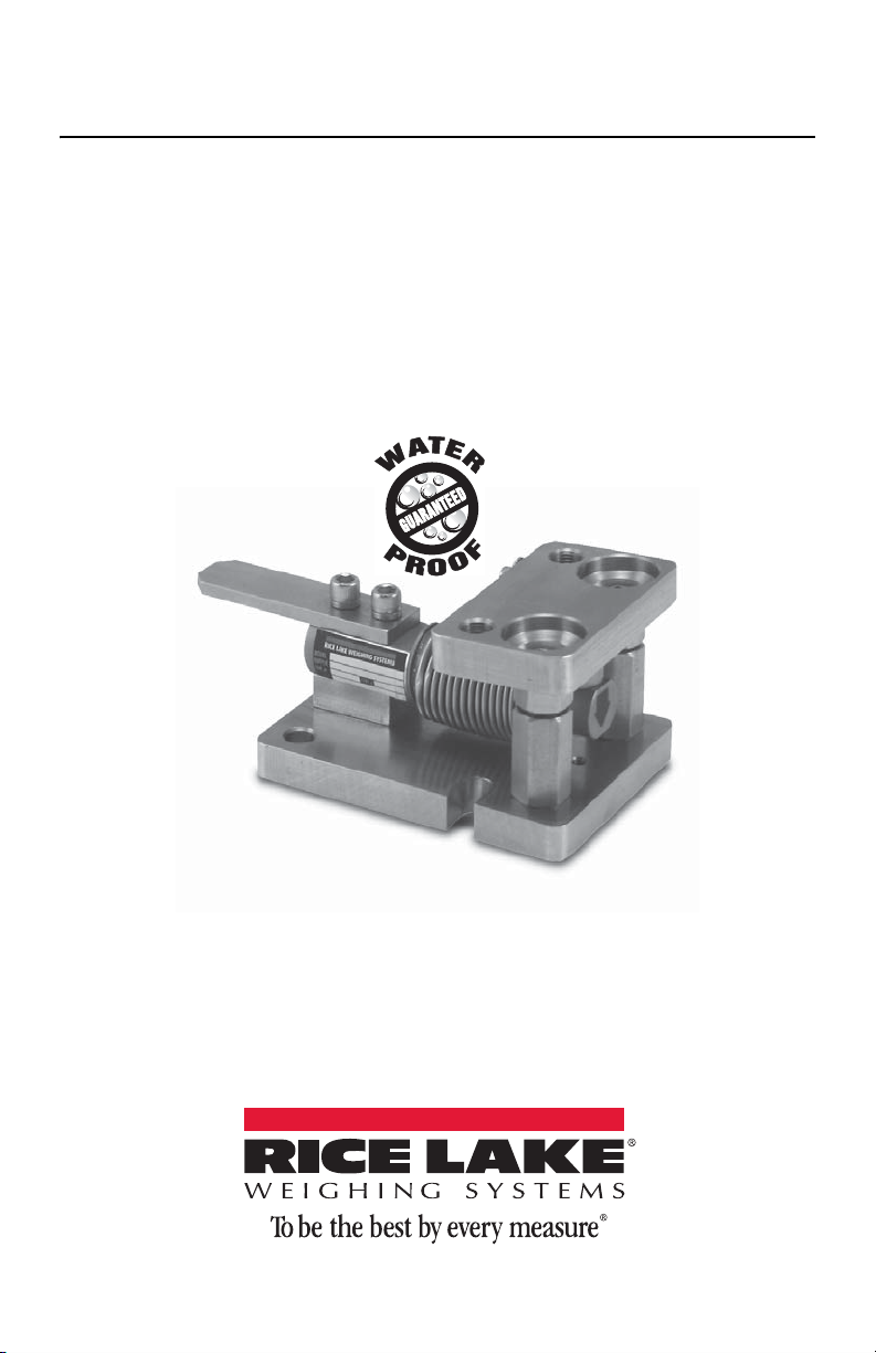
The Survivor® 1700HE Weigh Module
Kit is ideally suited for light to medium
capacity micro-ingredient batching and
mixing in a variety of hostile environments, especially where moisture is present. The load cell is stainless steel and
hermetically sealed with an IP rating of
IP68 to provide superior corrosion, moisture ingress, and mechanical protection.
The RLHBB and RLHTO load cells are
each waterproof guaranteed and OIML
C3 certified (20kg-5,000kg) to offer the
ultimate in durability and accuracy in any environment.
An important feature of the Survivor 1700HE is that the load may
be checked in one of two directions. This allows positioning in
one of two orientations for proper checking.
Integral jacking/shipping bolts offer a means to remove the load
from the load cell for quick removal and replacement of a load
cell and worry-free transport. The load introduction mechanism
also isolates the load cell from side loads, overloads, and underloads. For reliability
and accuracy, the Survivor 1700HE is the perfect mounting assembly for light capacity weighing.
The 1700HE modules are available from 5-250kg (11-550lb) capacities using
RLHBB cantilever beam load cells. In capacities from 500-5,000kg (1,100-11,000lb),
the units use RLHTO single-ended shear-beam load cells.
The installation should be planned by a qualified structural engineer. Each installation
is unique, and this manual is meant to serve only as a general guideline for installation.
Manuals can be viewed or downloaded from the Rice Lake Weighing
Systems website at
www.ricelake.com/manuals.
Introduction 1
Page 6
1.1 Safety
WARNING
Important
WARNING
Safety Symbol Definitions:
Indicates a potentially hazardous situation that, if not avoided
could result in death or serious injury, and includes hazards that
are exposed when guards are removed.
Indicates information about procedures that, if not observed,
could result in damage to equipment or corruption to and loss of
data.
General Safety
Do not install or work on this equipment unless you have read and
understand the instructions and warnings in this manual. Failure to
follow the instructions or heed the warnings could result in injury or
death. Contact any Rice Lake Weighing System dealer for
replacement manuals. Proper care is your responsibility.
Failure to heed may result in serious injury or death.
The installation should be planned by a qualified structural engineer. Each installation is unique, and this manual is meant to serve only as a general guideline for
installation.
DO NOT use for purposes other than weight measurement.
DO NOT use any load-bearing component that is worn beyond 5% of the original
dimension.
DO NOT use this product if any of the components are cracked.
DO NOT exceed the rated load limit of the unit.
DO NOT make alterations or modifications to the unit.
Contact Rice Lake Weighing Systems for replacement manuals. Proper care is
your responsibility.
2 Survivor® 1700HE Installation
Page 7

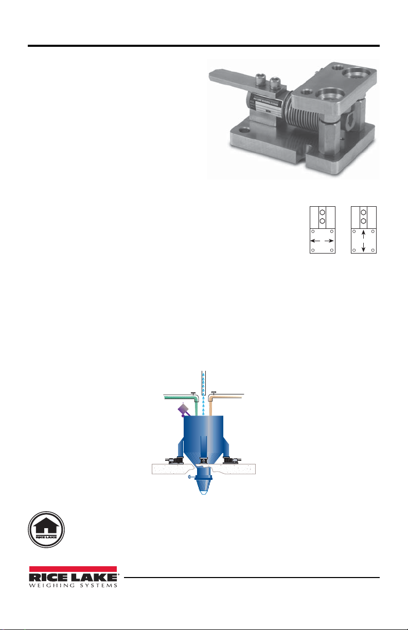
2.0 Mechanical Installation
LEVEL - 0.5
FLEXIBLE PIPING
J-BOX
Note
2.1
Installation Guidelines for Compression Weighing Assemblies
1. The mounting surface for the base plate and top plate must be level. After installation, the top and bottom plates must be level within ±0.5°. If the mounting surfaces are not level, then shims and/or grout may be used to level the mount.
If possible, check that the mount is level when the vessel is fully loaded because
excessive deflections in legs and supporting structures may cause additional side
forces that affect accuracy. Deflection of the mount’s top or base plate due to
loading should not exceed ±.5°. Reinforcement of legs or support structure may
be necessary. Vessels with long legs should have cross bracing applied between
adjacent legs to keep them from spreading under loads.
2. Compression mounting systems use 3, 4, or more mounts. More than eight mount
systems should be avoided as even weight distribution becomes extremely difficult to achieve. The load on each mount assembly should vary by no more than
20%. During installation, add shims where necessary to achieve correct load distribution.
3. If the actual load cel ls are used during installation of the weighing assembly,
extreme care must be taken to prevent overload damage. A tank or hopper weighing several tons can exert huge forces when dropped only a fraction of an inch.
The 1700HE series weigh modules incorporate a unique jacking bolt assembly
that should be used to remove the load from the cells during installation.
4. It is cruc ial that all piping or conduit
be horizontal and flexible. If flexible
piping is not used, make sure the distance from the vessel to the first pipe
support is 20-30 times the pipe diameter. For details, see our Weigh Mod-
ules & Vessel Weighing Systems
manual, PN 43918. In smaller, lower
capacity tanks and hoppers, isolating
the resultant forces becomes
extremely critical.
5. Load cells should not be installed in
the mounts until all welding is completed. The heat generated by welding current passing through a load cell can
damage the adhesive holding the strain gauge to the body. If possible, remove the
load cell when welding using the jacking/shipping bolts to mainta in fi nal height.
If welding is unavoidable after load cell installation, connect the ground in such a
way that the current does not flow through the load cell. For example, if welding
on the mount top plate, the ground must be connected to the vessel, not to the
mount base or support structure. Also, protect the load cell and cable from weld
splatter.
The arrow on the load cell should point in the direction of the load.
6. All support points should be equally stiff so that they deflect by the same amount
as the vessel is loaded.
Mechanical Installation 3
Page 8

2.2 Installing the RL1700HE Module
Top Plate
Jacking Spacer
Base Plate
Load Cell
Cable Guard Plate
Load Cell Bolt
Ground Strap
Load Cell Spacer
Load Button
Jacking Nuts
T
op Plate
Jacking Nuts
Load Cell
Cable Guard Plate
Load Cell Bolt
Load Cell Spacer
Jacking Spacer
Load Button
500-5000 kg
0-250 kg
Side View
Front View
Ground Strap
Base Plate
The type of installation, vessel support structure, and the surface upon which the
mount is to be placed determines the method of locating, attaching, and assembling
the 1700HE weigh module. Carefully consider three areas that commonly cause accuracy problems:
• Are the supporting legs adequately braced so they will not spread when the
system is fully loaded?
• Does the supporting structure have the necessary strength to prevent excessive
deflection when the system is fully loaded?
Is there attached equipment such as skirting, venting, or piping which is likely to
•
cause binding or lack of flexibility?
4 Survivor® 1700HE Installation
Page 9

After considering any areas that may cause accuracy problems, follow these installation
ABC D
Note
or
steps.
1. Determine where to position the mount and in which direction it should be oriented. The preferred mounting orientation for single ended beams is with the longitudinal axis of the load cell pointing toward the center of the vessel in circular
mounting configurations as illustrated in A and B in Figure 2-1.
Figure 2-1. Load Cell Orientation
Mounting configurations for square and rectangular vessels are shown in D an C
in Figure 2-1. For rectangular vessels, the load cell’s longitudinal axis should be
aligned along the vessel’s longest dimension as shown in Figure 4. In any application where a recurring side force is present in one direction, such as in a conveyor belt or roller platform, the longitudinal axis of the load cell should align
with that force.
The load may be checked in one of two directions. Make sure the top
plate moves in the proper direction (see step 2).
2. To assemble each module, remove the load cell bolts, position the load cell, and
pass the load cell bolts through the load cell and the load cell spacer, and thread
them into the base plate. Lift the top plate (do not loosen the retaining bolts) and
place the load button into the load hole of the load cell. Rest the top plate on the
load button. Verify that the retaining bolts do not protrude above the plane of the
top plate. Adjust if necessary.
During installation or transport, the jacking nuts may be used to isolate the top
plate from the load cell to avoid any damage to the load cell.
The load may be checked in one of two directions. To use the
alternate checking feature, lift the top plate clear of the load
button, turn the load button 90°, and restore the top plate to its
original position.
3. Lift and block the vessel to the same height as the assembled
mounts.
Use the jacking nuts to fully raise the top plate, automatically ensuring correct align-
4.
ment of the top plate and base plate during installation.
5. Remove the block from one support point and slide a mount into position.
6. If the mount is bein g fit ted under the leg of a vessel, verify that the leg’s center
line passes through the center of the load button.
Mechanical Installation 5
Page 10

7. Attach the top plate by bolting. Do not fully tighten as shimming may be
Note
necessary to level
The threads in the top plate of the 5-250kg modules are 1/2”-20 N.F.
threads. The threads in the top plate of the 500-5000kg modules are 3/4”10 N.C. threads.
8. Repeat steps 4, 5, and 6 for the remaining mounts. The vessel should now be supported on the mounts alone.
9. If necessary, move the vessel to its final position. Verify that there is no initial
misalignment between the base plate and top plate. Verify that the load button is
centered in the top plate to allow equal travel on either side.
10. If the jacking nuts were used to isolate the load cell from the load, lower them to
the jacking spacers to lower the vessel to rest on the load cells.
11. Attach the base plates to the foundation using anchors for concrete or by bolting
or welding to a steel structure. Verify that the base plates are no more than ±.5°
out of level. Shim as necessary.
12. Check that the top plates are no more than ±.5° out of level. Shim if necessary
and fully tighten the bolts.
13. The load distribution can be checked by lifting the vessel sightly at each support
point in turn or, more accurately, by exciting each load cell in turn and measuring
the output with a voltmeter. The variation in load among the cells should be no
more than 20%. Shim if necessary.
14. Check that the two screws securing the load cell to the base plate are tight.
6 Survivor® 1700HE Installation
Page 11

3.0 Load Cell Wiring
Drip Loop
1. Route the load cell cables so they will not be damaged or cut. Cable should not be
routed near heat sources greater than 150° F . Do not shorten any load cell cable.
The load cell is temperature compensated with the supplied length of cable. Cutting the cable will affect temperature compensation. Coil excess cable and protect it so it will not be mechanically damaged or be sitting in water.
2. Provide a drip loop in all cables so that water or other liquids will not run directly
down the cables onto either the load cells or the junction box. Attach load cell
cable to the dead structure, not the vessel.
3. If conduit protection is necessary against mechanical or rodent damage to the
load cell cables, use flexible conduit and conduit adapters at the load cells.
4. Connect cables for RLHBB, RLHTO, TEDEA 355, and TEDEA 3510 load cells
to the summing board in the junction box according to the guide shown below
and the labels on the terminal strips of the junction box. To verify the wiring
scheme, see the certification shipped with the load cell.
5. For better performance, use positive and negative remote sense lines if the wiring
run from the junction box to the indicator is longer than 25 feet.
RLHBB, 355 RLHTO, 3510
Load Cell
Wire Color
Green +EXC Blue +EXC
Black –EXC Black –EXC
Red +SIG White +SIG
White –SIG Red –SIG
Bare SHIELD Bare SHIELD
Blue +Sen Green +Sen
Brown -Sen Gray -Sen
Function
Load Cell Wire
Color
Function
Table 1: Load Cell Wiring
Load Cell Wiring 7
Page 12

4.0
Junction Box Connections, Adjustments & Calibration
1. Refer to Juncti on Box manual for trimming details.
2. Refer to indicator manual or “Technical Information” section in Rice Lake
Weighing Systems’ Load Cell Product Selection Guide (PN 22054) for system
calibration details.
8 Survivor® 1700HE Installation
Page 13

5.0 Troubleshooting
If the system powers up and gives some type of stable digital readout that varies with
the load on the system, any system problems are probably caused by factors other
than the load cells. The load cells are often blamed for a malfunctioning system, but
90% of the time, the problem lies elsewhere. Look for mechanical causes for your
problem first.
If the system can be calibrated but doesn’t return to zero, loses calibration, or demonstrates non-linearity or non-repeatability, see the following chart for possible causes
and do the following checks.
1. Check load cell mount for debris restricting load cell movement or debris
between scale and structure.
2. Check that tank/ vessel and mounts are plumb, level, and square at critical areas.
3. Check all piping and cond uit for connections which restrict vessel movement.
Symptom Possible Cause
No return to zero Mechanical binding or debris in seals or under load cells
Non-linearity Thermal expansion or deflection under load causing binding
Non-repeatability Loose load cell mount
Lost calibration Out of level or plumb
Drifting readout Moisture in junction box, cables or load cells
May have lost system calibration
or side load.
Drifting caused by moisture
Load cell overload or shack damage
Mechanical binding
Moisture problem
Mechanical binding
Mechanical binding
Table 1: Troubleshooting Chart
4. If check rods are used, loosen all connections to finger tight only for testing.
5. Check load cel l cables for physi cal or water damage.
6. Check all electrical connections, especially in the junction box.
If the problem still is not found:
7. Check possi ble indicator malfunction by using a load cell simulator to input a
known good signal into the indicator.
8. Disconnect each load cell’s signal leads at the junction box and check individual
load cell outputs with a multimeter. Then check input/output impedances for
comparison with load cell manufacturer’s specifications.
If after all these checks the problem still cannot be isolated, reconnect all but one load
cell. Replace load cell with a load cell simulator. Alternate so that each load cell is
individually disconnected and replaced with a simulator. If there is a problem with a
particular load cell, the symptom should disappear when that load cell is disconnected
and replaced with simulator.
Troubleshooting 9
Page 14

6.0 Maintenance and Replacement Parts
2 plcs
4
5
6
7
8
910
1
2
3
Item
No.
Rated Capacity: 5 - 250 kg
1 33036 Top Plate, Stainless Steel
2 125661 Coupling Nut, Stainless Steel
3 33035 Base Plate, Stainless Steel
4 33037 Load Cell Spacer, Stainless Steel
5 32678 Load Cell, RLHBB-5 kg, OIML C3
6 33038 Cable Guard Plate, Stainless Steel
7 33040 Load Cell Bolt, Stainless Steel
8 33039
9 42364 Cap Screw, 10-24 Stainless Steel
10 15141 Washer, Plain
Rated Capacity: 500 - 2,000 kg
1 159182 Top plate, stainless steel
2 125661 Coupling Nut, Stainless Steel
3 159181 Base Plate, Stainless Steel
4 159186 Load Cell Spacer, Stainless Steel
Part No. Description
32677 Load Cell, RLHBB-10 kg, OIML C3
31259 Load Cell, RLHBB-20 kg, OIML C3
31260 Load Cell, RLHBB-50 kg, OIML C3
31261 Load Cell, RLHBB-100 kg, OIML C3
31262 Load Cell, RLHBB-200 kg, OIML C3
31263 Load Cell, RLHBB-250 kg, OIML C3
und Strap
Gro
Table 1: Repair Parts List
10 Survivor® 1700HE Installation
Page 15

Item
No.
5 31253 Load Cell, RLHTO-500 kg, OIML C3
6 159187 Cable Guard Plate, Stainless Steel
7 33054 Load Cell Bolt, Stainless Steel
8 159183 Ground Strap
9 Machine Screw, 1/4-28 NF
10 Washer, Plain, 1/4
Rated Capacity: 5000 kg
1 33043 Top plate, stainless steel
2 33048 Checking/jacking assembly, stainless steel
3 33042 Base plate, stainless steel
4 33044 Load cell spacer, stainless steel
5 31252 Load cell, RLHTO-5000 kg, OIML C3
6 33045 Cable guard plate, stainless steel
7 33047 Load cell bolt set, stainless steel
8 33046
Part No. Description
31250 Load Cell, RLHTO-1000 kg, OIML C3
31251 Load Cell, RLHTO-2000 kg, OIML C3
Ground strap
Table 1: Repair Parts List
Maintenance and Replacement Parts 11
Page 16

RL1700HE Limited Warranty
Rice Lake Weighing Systems (RLWS) warrants that all RLWS brand load cells properly installed by a Distributor or Original Equipment Manufacturer (OEM) will operate per written specifications. All load cell products are warranted against defects in
materials and workmanship for two (2) years. Products marked as “waterproof” are
warranted against defects in materials and wor k man s h ip re l a ting to moisture ingress.
RL WS warrants that the equipment sold hereunder will conform to the current written
specifications authorized by RLWS. RLWS warrants the equipment against faulty
workmanship and defective materials. If any equipment fails to conform to these warranties, RLWS will, at its option, repair or replace such goods returned within the
warranty period subject to the following conditions:
• Upon discovery by Buyer of such non-conformity, RL WS will be given prompt
written notice with a detailed explanation of the alleged deficiencies.
• Examination of such equipment by RLWS confirms that the non-conformity
actually exists, and was not caused by accident, misuse, neglect, alteration,
improper installation, improper repair or improper testing; RLWS shall be the
sole judge of all alleged non-conformities.
• Such equipment has not been modified, altered, or changed by any person
other than RLWS or its duly authorized repair agents.
• RLWS will have a reasonable time to repair or replace the defective equip-
ment. Buyer is responsible for shipping charges both ways.
• In no event will RLWS be responsible for travel time or on-location repairs,
including assembly or disassembly of equipment, nor will RLWS be liable for
the cost of any repairs made by others.
THESE WARRANTIES EXCLUDE ALL OTHER WARRANTIES, EXPRESSED
OR IMPLIED, INCLUDING WITHOUT LIMITATION WARRANTIES OF MERCHANTABILITY OR FITNESS FOR A PARTICULAR PURPOSE. NEITHER
RLWS NOR DISTRIBUTOR WILL, IN ANY EVENT, BE LIABLE FOR INCIDENTAL OR CONSEQUENTIAL DAMAGES.
RLWS AND BUYER AGREE THAT RLWS’S SOLE AND EXCLUSIVE LIABILITY HEREUNDER IS LIMITED TO REPAIR OR REPLACEMENT OF SUCH
GOODS. IN ACCEPTING THIS WARRANTY, THE BUYER WAIVES ANY AND
ALL OTHER CLAIMS TO WARRANTY.
SHOULD THE SELLER BE OTHER THAN RLWS, THE BUYER AGREES TO
LOOK ONLY TO THE SELLER FOR WARRANTY CLAIMS.
No terms, conditions, understanding, or agreements purporting to modify the terms of
this warranty shall have any legal effect unless made in writing and signed by a corporate officer of RLWS and the Buyer.
© Rice Lake Weighing Systems, Inc. Rice Lake, WI USA. All Rights Reserved.
RICE LAKE WEIGHING SYSTEMS • 230 WEST COLEMAN STREET
RICE LAKE, WISCONSIN 54868 • USA
12 Survivor® 1700HE Installation
Page 17

Notes
Maintenance and Replacement Parts 13
Page 18

Notes
14 Survivor® 1700HE Installation
Page 19

Page 20

230 W. Coleman St. • Rice Lake, WI 54868 • USA
U.S. 800-472-6703 • Canada/Mexico 800-321-6703 • International 715-234-9171 • Europe +31 (0) 88 2349171
www.ricelake.com www.ricelake.mx www.ricelake.eu www.ricelake.co.in m.ricelake.com
© Rice Lake Weighing Systems 04/2014 33318 Rev A
 Loading...