

Page 1
160-10-7
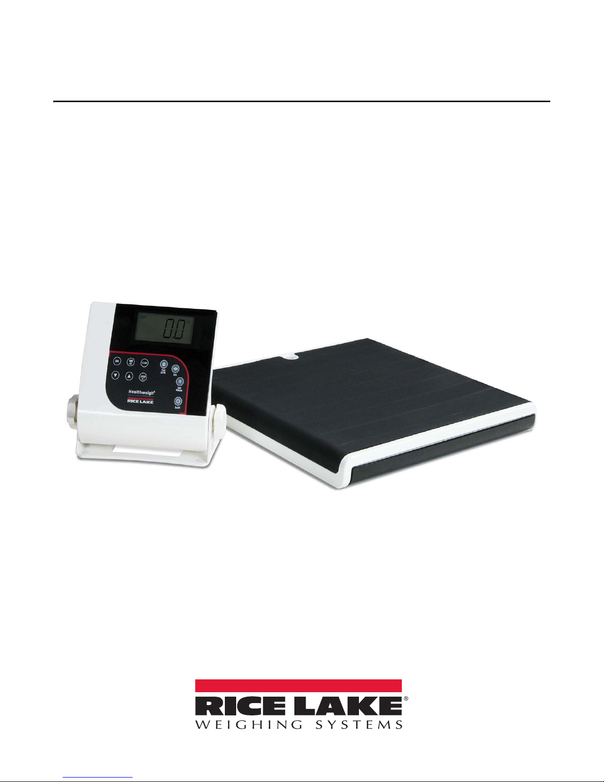
Low Profile Digital Physician Scale
Firmware Version 11525
Technical Manual
PN 185558 Rev CAugust 18, 2017
Page 2

An ISO 9001 registered company
© Rice Lake Weighing Systems. All rights reserved.
®
Rice Lake Weighing Systems
is a registered trademark of
Rice Lake Weighing Systems.
All other brand or product names within this publication are trademarks or
registered trademarks of their respective companies.
All information contained within this publication is, to the best of our knowledge, complete and
accurate at the time of publication. Rice Lake Weighing Systems reserves the right to make
changes to the technology, features, specifications and design of the equipment without notice.
The most current version of this publication, software, firmware and all other product
updates can be found on our website:
www.ricelake.com
Page 3

Contents
Technical training seminars are available through Rice Lake Weighing Systems.
Course descriptions and dates can be viewed at www.ricelake.com/training
or obtained by calling 715-234-9171 and asking for the training department.
Contents
1.0 Introduction................................................................................................................................................... 1
1.1 Standard Features. . . . . . . . . . . . . . . . . . . . . . . . . . . . . . . . . . . . . . . . . . . . . . . . . . . . . . . . . . . . . . . . . . . . . . . . . . . . . . 1
1.2 Options. . . . . . . . . . . . . . . . . . . . . . . . . . . . . . . . . . . . . . . . . . . . . . . . . . . . . . . . . . . . . . . . . . . . . . . . . . . . . . . . . . . . . . . 1
1.3 Safety. . . . . . . . . . . . . . . . . . . . . . . . . . . . . . . . . . . . . . . . . . . . . . . . . . . . . . . . . . . . . . . . . . . . . . . . . . . . . . . . . . . . . . . . 2
2.0 Scale Assembly............................................................................................................................................ 3
2.1 Unpacking Scale . . . . . . . . . . . . . . . . . . . . . . . . . . . . . . . . . . . . . . . . . . . . . . . . . . . . . . . . . . . . . . . . . . . . . . . . . . . . . . . 3
2.1.1 Repacking . . . . . . . . . . . . . . . . . . . . . . . . . . . . . . . . . . . . . . . . . . . . . . . . . . . . . . . . . . . . . . . . . . . . . . . . . . 3
2.2 Setting Up Scale . . . . . . . . . . . . . . . . . . . . . . . . . . . . . . . . . . . . . . . . . . . . . . . . . . . . . . . . . . . . . . . . . . . . . . . . . . . . . . . 3
2.2.1 Leveling the Scale . . . . . . . . . . . . . . . . . . . . . . . . . . . . . . . . . . . . . . . . . . . . . . . . . . . . . . . . . . . . . . . . . . . . 3
2.3 Indicator. . . . . . . . . . . . . . . . . . . . . . . . . . . . . . . . . . . . . . . . . . . . . . . . . . . . . . . . . . . . . . . . . . . . . . . . . . . . . . . . . . . . . . 4
2.3.1 Load Cell Connections. . . . . . . . . . . . . . . . . . . . . . . . . . . . . . . . . . . . . . . . . . . . . . . . . . . . . . . . . . . . . . . . . 4
2.3.2 Insert Batteries. . . . . . . . . . . . . . . . . . . . . . . . . . . . . . . . . . . . . . . . . . . . . . . . . . . . . . . . . . . . . . . . . . . . . . . 5
2.3.3 Optional Power Connections . . . . . . . . . . . . . . . . . . . . . . . . . . . . . . . . . . . . . . . . . . . . . . . . . . . . . . . . . . . . 5
2.3.4 Dimensions. . . . . . . . . . . . . . . . . . . . . . . . . . . . . . . . . . . . . . . . . . . . . . . . . . . . . . . . . . . . . . . . . . . . . . . . . . 6
3.0 Operation....................................................................................................................................................... 7
3.1 Powering the Scale . . . . . . . . . . . . . . . . . . . . . . . . . . . . . . . . . . . . . . . . . . . . . . . . . . . . . . . . . . . . . . . . . . . . . . . . . . . . . 7
3.2 Set Units. . . . . . . . . . . . . . . . . . . . . . . . . . . . . . . . . . . . . . . . . . . . . . . . . . . . . . . . . . . . . . . . . . . . . . . . . . . . . . . . . . . . . . 7
3.3 Weigh Mode. . . . . . . . . . . . . . . . . . . . . . . . . . . . . . . . . . . . . . . . . . . . . . . . . . . . . . . . . . . . . . . . . . . . . . . . . . . . . . . . . . . 8
3.4 Hold Release . . . . . . . . . . . . . . . . . . . . . . . . . . . . . . . . . . . . . . . . . . . . . . . . . . . . . . . . . . . . . . . . . . . . . . . . . . . . . . . . . . 8
3.5 Preset Tare . . . . . . . . . . . . . . . . . . . . . . . . . . . . . . . . . . . . . . . . . . . . . . . . . . . . . . . . . . . . . . . . . . . . . . . . . . . . . . . . . . . 8
3.6 Toggle Tare . . . . . . . . . . . . . . . . . . . . . . . . . . . . . . . . . . . . . . . . . . . . . . . . . . . . . . . . . . . . . . . . . . . . . . . . . . . . . . . . . . . 8
3.7 Body Mass Index . . . . . . . . . . . . . . . . . . . . . . . . . . . . . . . . . . . . . . . . . . . . . . . . . . . . . . . . . . . . . . . . . . . . . . . . . . . . . . . 8
3.7.1 LB Mode. . . . . . . . . . . . . . . . . . . . . . . . . . . . . . . . . . . . . . . . . . . . . . . . . . . . . . . . . . . . . . . . . . . . . . . . . . . . 8
3.7.2 KG Mode . . . . . . . . . . . . . . . . . . . . . . . . . . . . . . . . . . . . . . . . . . . . . . . . . . . . . . . . . . . . . . . . . . . . . . . . . . . 9
4.0 Communications ........................................................................................................................................ 10
4.1 Pushbutton Keypad Print. . . . . . . . . . . . . . . . . . . . . . . . . . . . . . . . . . . . . . . . . . . . . . . . . . . . . . . . . . . . . . . . . . . . . . . . 10
4.2 Escape Protocol. . . . . . . . . . . . . . . . . . . . . . . . . . . . . . . . . . . . . . . . . . . . . . . . . . . . . . . . . . . . . . . . . . . . . . . . . . . . . . . 10
4.3 Maintenance Protocol . . . . . . . . . . . . . . . . . . . . . . . . . . . . . . . . . . . . . . . . . . . . . . . . . . . . . . . . . . . . . . . . . . . . . . . . . . 12
4.4 USB Connection. . . . . . . . . . . . . . . . . . . . . . . . . . . . . . . . . . . . . . . . . . . . . . . . . . . . . . . . . . . . . . . . . . . . . . . . . . . . . . . 12
4.5 Optional Bluetooth®. . . . . . . . . . . . . . . . . . . . . . . . . . . . . . . . . . . . . . . . . . . . . . . . . . . . . . . . . . . . . . . . . . . . . . . . . . . . 16
5.0 Configuration.............................................................................................................................................. 18
5.1 Scale Navigation . . . . . . . . . . . . . . . . . . . . . . . . . . . . . . . . . . . . . . . . . . . . . . . . . . . . . . . . . . . . . . . . . . . . . . . . . . . . . . 18
5.1.1 Change Parameters. . . . . . . . . . . . . . . . . . . . . . . . . . . . . . . . . . . . . . . . . . . . . . . . . . . . . . . . . . . . . . . . . . 18
5.1.2 Enter Numbers. . . . . . . . . . . . . . . . . . . . . . . . . . . . . . . . . . . . . . . . . . . . . . . . . . . . . . . . . . . . . . . . . . . . . . 18
5.1.3 Save and Return to Main Menu . . . . . . . . . . . . . . . . . . . . . . . . . . . . . . . . . . . . . . . . . . . . . . . . . . . . . . . . . 18
5.2 Test Menu . . . . . . . . . . . . . . . . . . . . . . . . . . . . . . . . . . . . . . . . . . . . . . . . . . . . . . . . . . . . . . . . . . . . . . . . . . . . . . . . . . . 18
5.3 Press . The indicator will continue with the self test and finish in the weigh mode.User Menu . . . . . . . . . . . . . . . . . . . 19
5.4 Setup Mode . . . . . . . . . . . . . . . . . . . . . . . . . . . . . . . . . . . . . . . . . . . . . . . . . . . . . . . . . . . . . . . . . . . . . . . . . . . . . . . . . . 20
5.4.1 Setup Mode Main Menu. . . . . . . . . . . . . . . . . . . . . . . . . . . . . . . . . . . . . . . . . . . . . . . . . . . . . . . . . . . . . . . 20
5.4.2 Programming Mode . . . . . . . . . . . . . . . . . . . . . . . . . . . . . . . . . . . . . . . . . . . . . . . . . . . . . . . . . . . . . . . . . . 21
5.5 Default Menu. . . . . . . . . . . . . . . . . . . . . . . . . . . . . . . . . . . . . . . . . . . . . . . . . . . . . . . . . . . . . . . . . . . . . . . . . . . . . . . . . 22
5.5.1 Set to Default . . . . . . . . . . . . . . . . . . . . . . . . . . . . . . . . . . . . . . . . . . . . . . . . . . . . . . . . . . . . . . . . . . . . . . . 22
5.6 Scale Calibration . . . . . . . . . . . . . . . . . . . . . . . . . . . . . . . . . . . . . . . . . . . . . . . . . . . . . . . . . . . . . . . . . . . . . . . . . . . . . . 22
6.0 Maintenance and Troubleshooting........................................................................................................... 24
6.1 Maintenance. . . . . . . . . . . . . . . . . . . . . . . . . . . . . . . . . . . . . . . . . . . . . . . . . . . . . . . . . . . . . . . . . . . . . . . . . . . . . . . . . . 24
6.1.1 Basic Maintenance. . . . . . . . . . . . . . . . . . . . . . . . . . . . . . . . . . . . . . . . . . . . . . . . . . . . . . . . . . . . . . . . . . . 24
©Rice Lake Weighing Systems ● All Rights Reserved i
Page 4

160-10-7 Low Profile Digital Physician Scale
Rice Lake continually offers web-based video training on a growing selection
of product-related topics at no cost. Visit www.ricelake.com/webinars
6.1.2 Cleaning. . . . . . . . . . . . . . . . . . . . . . . . . . . . . . . . . . . . . . . . . . . . . . . . . . . . . . . . . . . . . . . . . . . . . . . . . . . 24
6.2 Troubleshooting. . . . . . . . . . . . . . . . . . . . . . . . . . . . . . . . . . . . . . . . . . . . . . . . . . . . . . . . . . . . . . . . . . . . . . . . . . . . . . . 24
6.3 Specifications. . . . . . . . . . . . . . . . . . . . . . . . . . . . . . . . . . . . . . . . . . . . . . . . . . . . . . . . . . . . . . . . . . . . . . . . . . . . . . . . . 25
7.0 Low Profile Digital Physician Scale Limited Warranty............................................................................ 26
ii Visit our website www.ricelake.com
Page 5
Introduction
1.0 Introduction
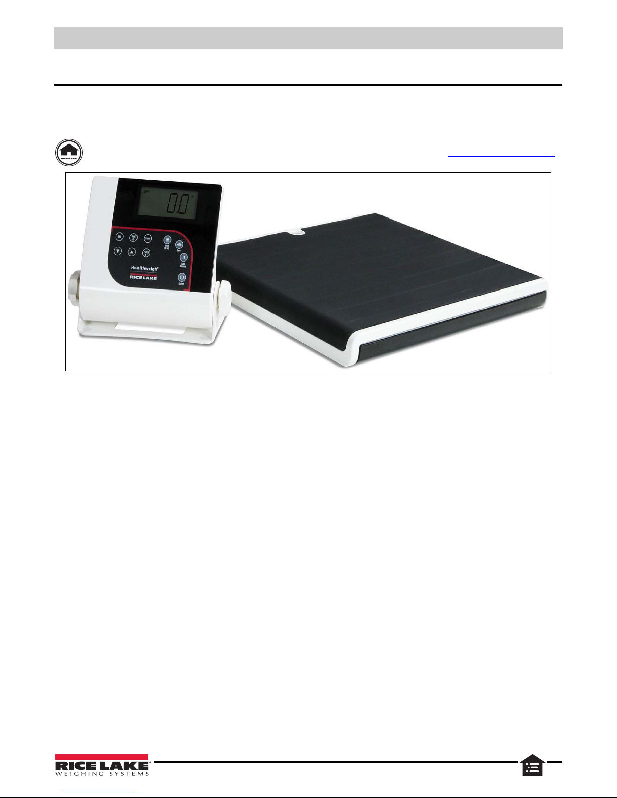
The 160-10-7 Low-Profile Digital Physician Scale is efficiently designed to provide accurate, reliable and repeatable weight
measurements. The large, stand-alone indicator can be placed on a table or the floor. It can also be mounted to a wall using the
sturdy, built-in bracket.
Manuals can be viewed or downloaded from the Rice Lake Weighing Systems website at www.ricelake.com/manuals
Figure 1-1. Rice Lake Low Profile Digital Physician Scale (RL160-10-7)
1.1 Standard Features
• Capacity: 550 lb x 0.2 lb (250 kg x 0.1 kg)
• Platform dimensions (L x W x H): 14.4'' x 14.4'' x 1.65''
• Motiontrap™ (movement compensation technology)
• Large LCD display
• 6 AA alkaline batteries
• Low battery indicator/automatic power-off
• BMI (body mass index) function
• Hold function
• Unit of Measure: lb only, kg only, lb/kg
• EMR compatible
1.2 Options
Medical Transport/Carrying Case (PN 107445)
©Rice Lake Weighing Systems ● All Rights Reserved 1
Page 6
160-10-7 Low-Profile Digital Physician Scale
DANGER
WARNING
CAUTION
IMPORTANT
WARNING
1.3 Safety
Safety Signal Definitions:
Indicates an imminently hazardous situation that, if not avoided, will result in death or serious injury. Includes
hazards that are exposed when guards are removed.
Indicates a potentially hazardous situation that, if not avoided could result in serious injury or death. Includes
hazards that are exposed when guards are removed.
Indicates a potentially hazardous situation that, if not avoided, could result in minor or moderate injury.
Indicates information about procedures that, if not observed, could result in damage to equipment or corruption
to and loss of data.
General Safety
Do not operate or work on this equipment unless this manual has been read and all instructions are understood.
Failure to follow the instructions or heed the warnings could result in injury or death. Contact any Rice Lake
Weighing Systems dealer for replacement manuals.
Failure to heed could result in serious injury or death.
Subjects with disabilities or who are physically frail, should always be assisted on and off the scale.
Do not use the scale on slippery surfaces, such as a wet floor.
Do not use this scale when body/feet are wet, such as after taking a bath.
Do not transport the scale while someone is standing on it.
To avoid cross contamination, the scale should be cleaned regularly.
Do not allow minors (children) or inexperienced persons to operate this scale.
Do not jump on the scale.
Do not use in the presence of flammable materials.
Use the scale only to determine weight of people while standing.
Do not drop the scale or subject it to violent shocks.
For accurate weighing, the scale must be placed on a flat, stable surface. Thin carpeting is fine but not recommended.
Weight exceeding the maximum capacity (550 lb/250 kg) may damage scale.
Operating at voltages and frequencies other than specified could damage the equipment.
If the LO Bat indicator activates, replace the batteries or connect the scale to an AC power source as soon as possible.
Do not use in a wet or humid environment.
Do not make alterations or modifications to the scale.
2 Visit our website www.RiceLake.com
Page 7
Scale Assembly
IMPORTANT
Note
2.0 Scale Assembly
2.1 Unpacking Scale
Place the unopened shipping container in an open are a with room for unpacking the scale. Parts included:
• Scale base and indicator
• Six AA batteries
• AC adapter
• USB 2.0 Cable AM/BM 1.5 M
• Serial cable 9.5' with female DB9 and RJ45 connectors
2.1.1 Repacking
The 160-10-7 must be properly packed with sufficient packing materials prior to being moved or shipped. Retain the original
shipping materials and container, if possible.
Damage caused by improper packaging is not covered by the warranty.
2.2 Setting Up Scale
Place the scale on a hard level surface for the most accurate weighme nts.
Thin carpeting is acceptable but is not recommended. Weighing on carpet can cause a weight discrepancy.
2.2.1 Leveling the Scale
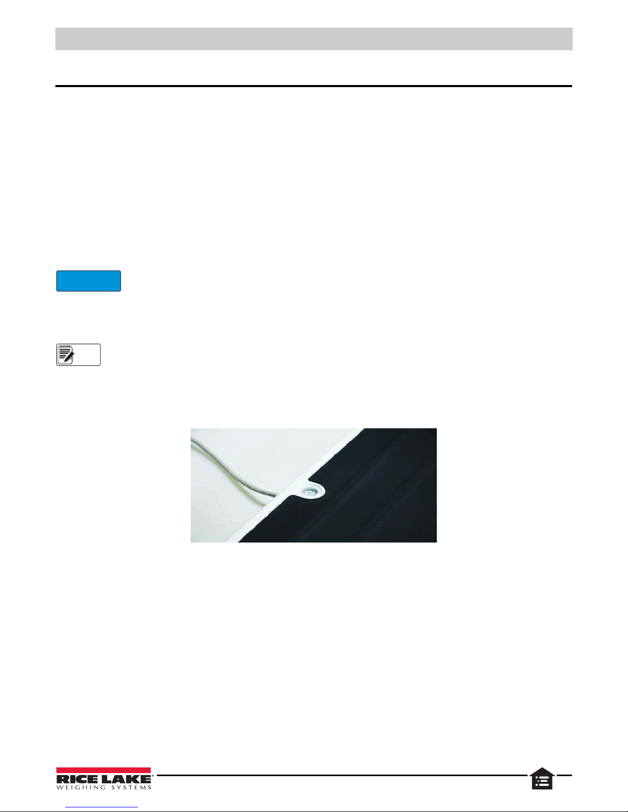
Use the bubble level to check for level and adjust feet as needed.
Figure 2-1. Bubble Level
©Rice Lake Weighing Systems ● All Rights Reserved 3
Page 8
160-10-7 Low-Profile Digital Physician Scale
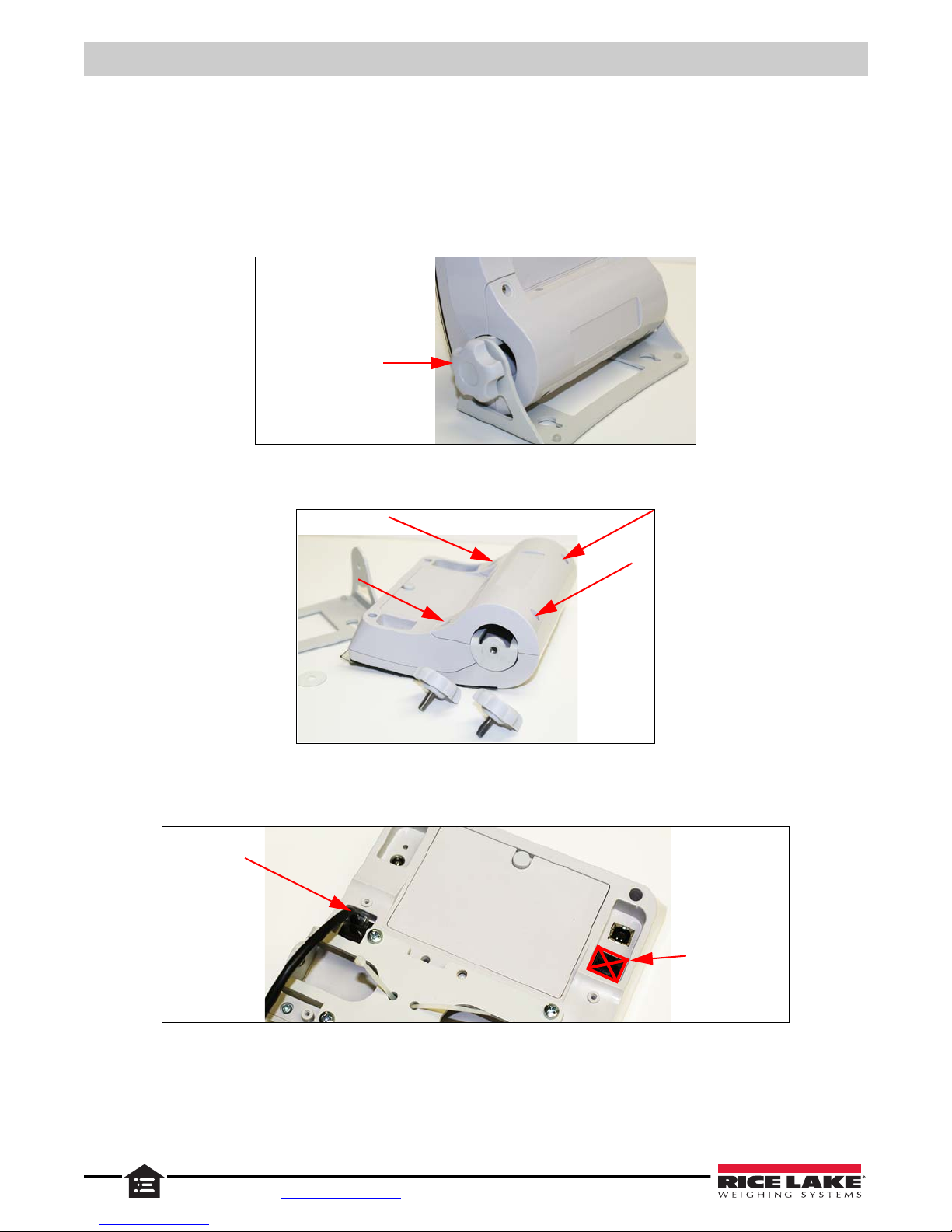
Unscrew tilt stand
knobs and remove tilt
stand from indicator
Load Cell
Connection
Do not use this
connection for
Load Cells.
2.3 Indicator
Use the following sections to install and setup the Rice Lake Indicator.
2.3.1 Load Cell Connections
The scale comes with 10' of load cell cable; cable must be connected to the indicator.
To gain access to the load cell connection on the indicator:
1. Unscrew and remove the tilt stand bracket from the indicator.
Figure 2-2. Remove Tilt Stand
2. Remove the four back retaining screws to remove the back cover to the indicator.
3. Plug the end of the load cell cable into the load cell connection. When it clicks the load cell cable is properly seated
into the connection.
4. Reinstall the backplate and attach to the tilt stand.
4 Visit our website www.RiceLake.com
Figure 2-3. Remove Back Cover
Figure 2-4. Load Cell Connection Point
Page 9
2.3.2 Insert Batteries
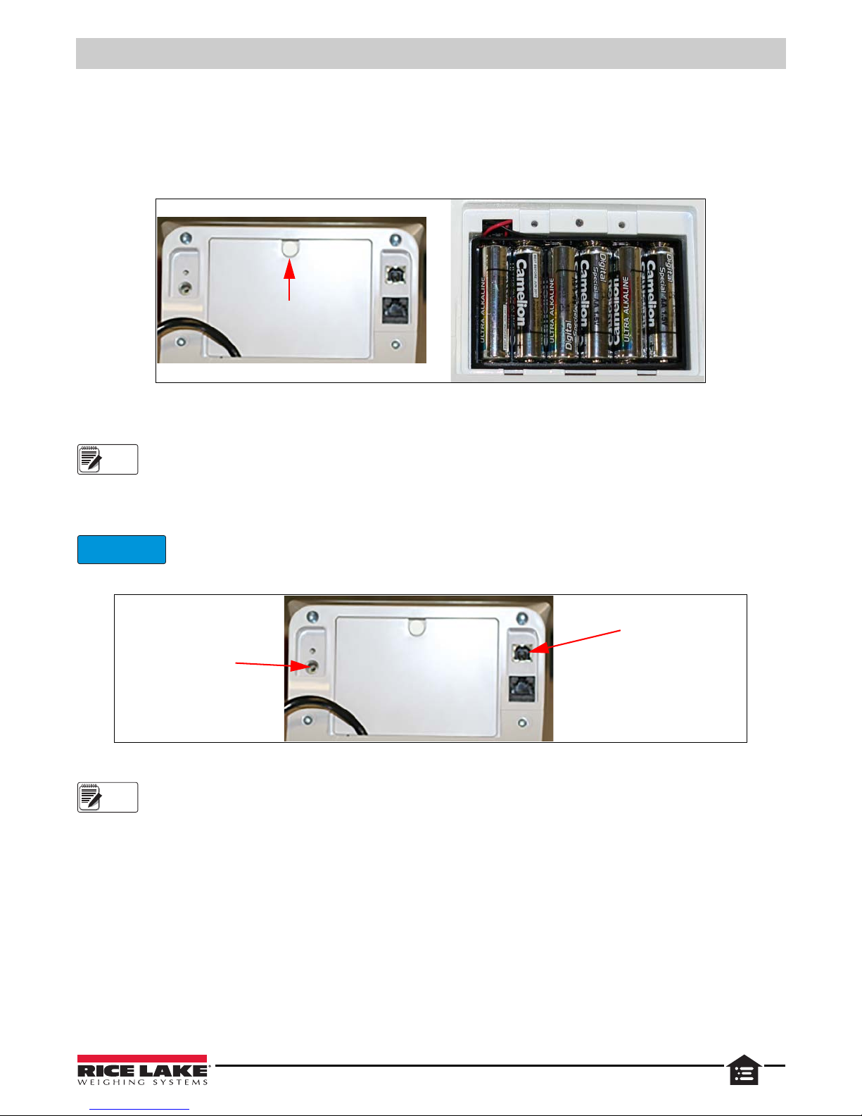
Thumb
Screw
Note
IMPORTANT
AC Power Connection
USB Power Connection
Note
The six AA batteries that come with the scale offer an average of 25 hours of continuous u se.
To install the batteries:
1. Open the battery chamber cover by turning the thumbscrew to the left and remove the cover.
2. Insert batteries into the battery chamber as illustrated in the back of the chamber.
Figure 2-5. Battery Chamber
3. Put the cover in place and turn the thumbscrew to the right to secure it.
Batteries must be removed from the unit prior to long periods of disuse or long term storage.
Scale Assembly
2.3.3 Optional Power Connections
Rice Lake Weighing Systems offers optional AC adapters to use when power is available. USB power can also be used.
Rice Lake Weighing Systems offers replacement AC adapters for the 160-10-7; utilizing an
adapter not supplied by us voids all warranties.
Figure 2-6. Power Connection Site
If an external power supply or USB power supply is connected, the battery flag on the display is turned off.
When using battery or USB power supply, the back-light power is deducted to 60%.
©Rice Lake Weighing Systems ● All Rights Reserved 5
Page 10
160-10-7 Low-Profile Digital Physician Scale
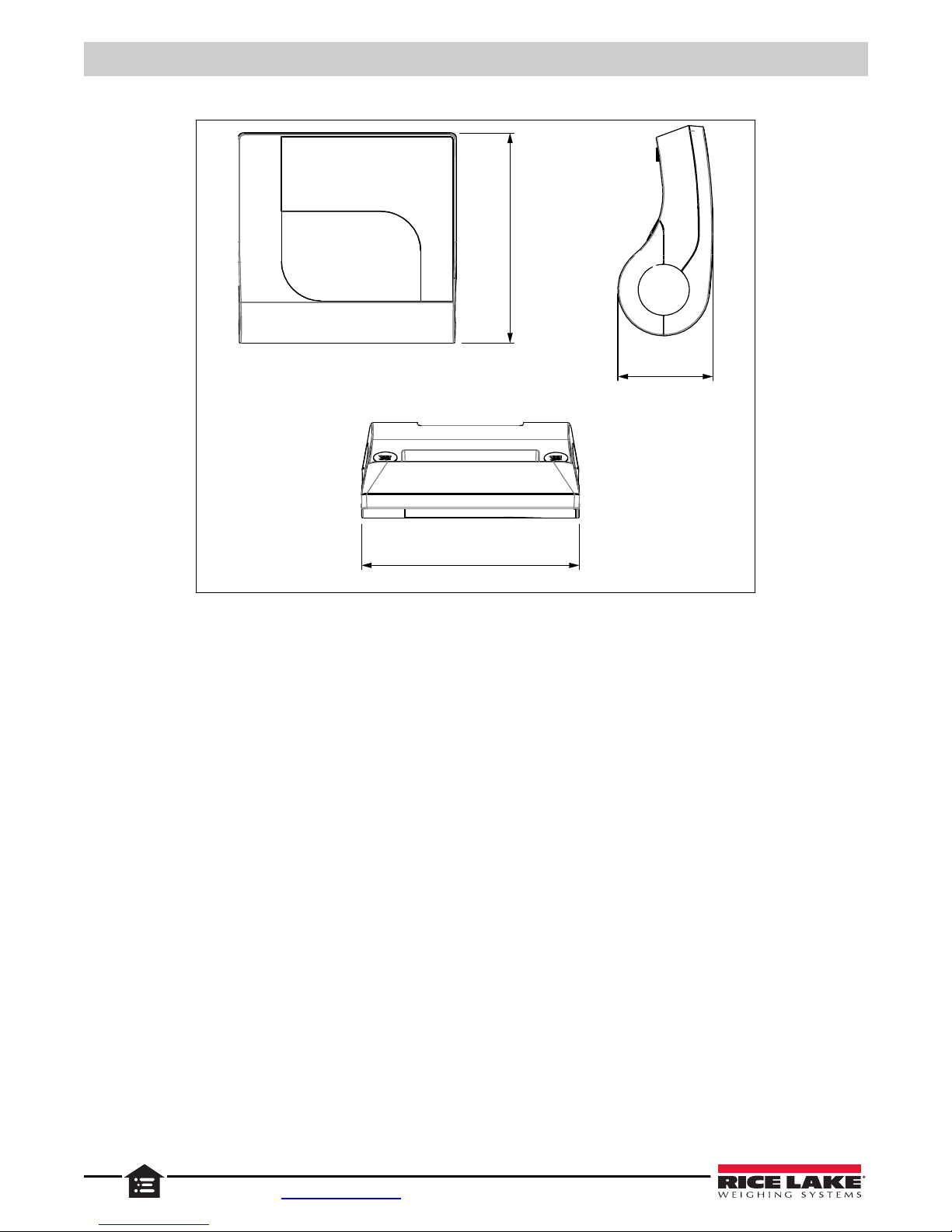
6.3"
160 mm
6.5"
160 mm
2.9"
72.4 mm
2.3.4 Dimensions
Figure 2-7. Indicator Dimensions
6 Visit our website www.RiceLake.com
Page 11
3.0 Operation
1
2
3
4
5
6
7
9
8
IMPORTANT
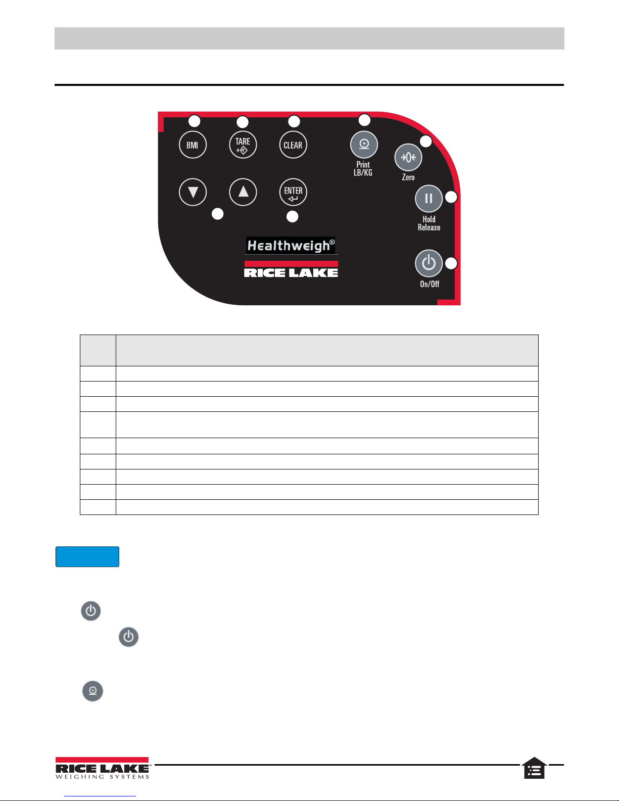
This section describes the indicator, functionality of each button and basic scale operations.
Figure 3-1. Indicator Front Panel
Operation
Item
No.
1 Body Mass Index (BMI) – enable in configuration; a stable weight is required
2 TARE – Subtract weight of accessory items, required by subject, from the scale. Example: oxygen unit or other equipment
3 CLEAR – return to weigh mode after BMI value displays
4 Print – long key press sends data out from the RS-232 port or USB port
LB/KG – short key press toggles kilograms and pounds (must be enabled in configuration mode); disabled in BMI mode
5
Zero – sets the weight to
6 Hold/Release – press to keep the current weight value displayed; press again to clear the weight; disabled in BMI mode
7 On/Off – turns the scale on and off
8 ENTER – accepts an entered value and moves to the next parameter; long press during start up enters the ID display
9 Arrows – Adjust the value of the flashing digit/number
The front panel keys are sensitive, press gently.
0.0 and displays ZERO; weight must be stable and less than 2% of capacity to be cleared
Table 3-1. Indicator Key Functions
3.1 Powering the Scale
Press to turn the scale on. After a system test, 0.0 displays.
Press and hold until OFF displays to turn the scale off.
Function
3.2 Set Units
Press to toggle from kg to lb, display unit desired for weights.
©Rice Lake Weighing Systems ● All Rights Reserved 7
Page 12
160-10-7 Low-Profile Digital Physician Scale
Note
TARE
T
TARE
T
Note
TARE
T
ENTER
TARE
T
BMI
3.3 Weigh Mode
Have subject to be weighed step onto the scale. The weight value displays. When the weight is stable, the LOCK annunciator
displays and an audible tone indicates the end of the weighing process.
3.4 Hold Release
1. Have subject to be weighed step onto the scale.
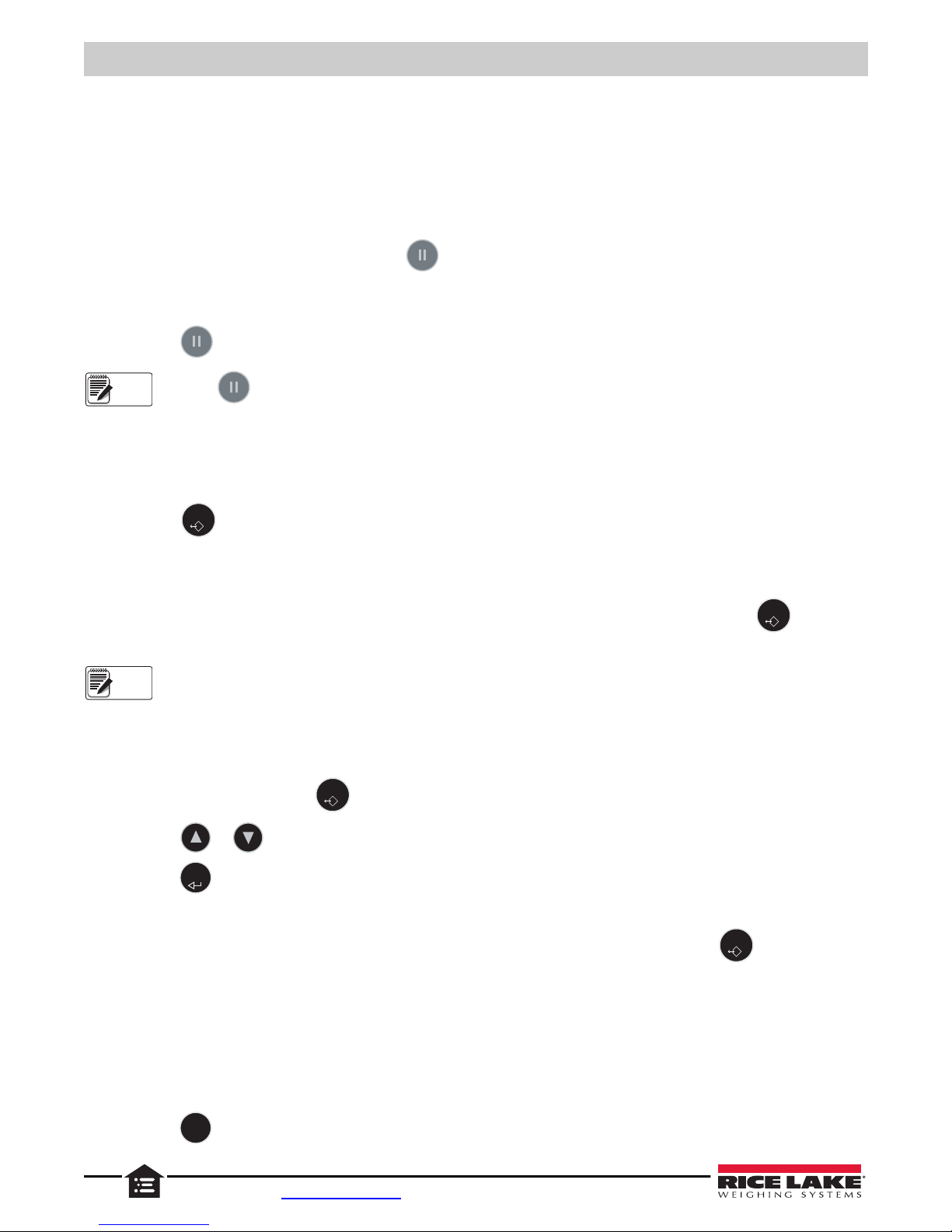
2. When weight is stable (Section 3.3), press .
3. Have subject step off the scale. The weight continues to display,
HOLD annunciator displays. The ZERO function is not
available until HOLD is released.
4. Press to release the hold.
Pressing prior to stepping on the scale will also hold the weight display.
0.0 is displayed and the ZERO annunciator is on.
3.5 Preset Tare
1. With the weight at 0.0 and ZERO displayed, place accessory items required by subject, (e.g. oxygen unit or other
equipment) onto the scale. Wait for the weight to stabilize (Section 3.3).
2. Press until
3. Remove the additional items from the scale. A negative weight and
0.0 is displayed and the NET annunciator is on.
NET display.
4. Have subject step on the scale with accessory items. The net weight displays.
5. The weight of accessory items remain stored in memory. To cancel the tare weight, press and hold until the
weight returns to
The tare weight is also canceled when the scale is turned off.
0.0 and the GROSS annunciator displays.
3.6 Toggle Tare
When the weight of the accessory items is known, use this function to enter the weight manually.
1. With the weight at
0.0
, press . The default tare value (33.0 lb/15.0 kg) displays.
2. Press or to change the tare weight value.
3. Press to accept the entered value and start the tare function. A negative weight and
4. Have subject step on the scale with the accessory items. The weight is displayed and the
5. The weight of the additional items remain stored in memory. To cancel the tare weight, press .
3.7 Body Mass Index
3.7.1 LB Mode
Set the units to LB if needed.
1. With the weight at 0.0 and the ZERO annunciator on, step onto the scale. The weight value displays, the LOCK
annunciator is on and an audible tone indicates the end of the weighing process.
2. Press . The
8 Visit our website www.RiceLake.com
BMI and FT/IN annunciators display and a default value of 5' and 7.5'' (5-0.75) is flashing.
NET displays.
NET annunciator remains on.
Page 13
3. Press or to adjust the height value.
ENTER
CLEAR
BMI
ENTER
CLEAR
Operation
4. Press to accept the entered height value. The BMI value is displayed and the
BMI annunciator is on.
5. Press to turn off the BMI function and return to the weigh mode.
3.7.2 KG Mode
Set the units to KG if needed.
1. With the weight at 0.0 and the ZERO annunciator on, step onto the scale. The weight value displays, the LOCK
annunciator is on and an audible tone indicates the end of the weighing process.
2. Press . The
3. Press or to adjust the height value.
4. Press to accept the entered height value. The BMI value is displayed and the
5. Press to turn off the BMI function and return to the weigh mode.
BMI and FT/IN annunciators display and a default value of 170.0 cm (170.0) is flashing.
BMI annunciator is on.
©Rice Lake Weighing Systems ● All Rights Reserved 9
Page 14
160-10-7 Low-Profile Digital Physician Scale
IMPORTANT
Note
4.0 Communications
The indicator comes with an RS-232 port which enables weight data to be transmitted to other equipment, such as a computer
or printer. The RS-232 cable with DB-9 connector (PN 100719) is available from Rice Lake Weighing Systems.
page 12 shows where the RS-232 connection is located on the indicator.
Always use medical grade isolators for USB and RJ45 when connected to non-medical equipment, or when
other medical equipment is connected to patient during procedure.
The RS-232 parameters are 9600 baud (selectable in the programming mode), 8 data bits, 1 stop bit, no parity and no
handshaking.
There are three methods of communication:
• Pushbutton keypad print
• Escape protocol
• Maintenance protocol
4.1 Pushbutton Keypad Print
With a stable, in-range weight, press and hold for at least three seconds, or until the scale emi t s two quick beeps.
If the scale does not beep after five seconds, release the button as the weight was either in motion, or out of
range.
Figure 4-3 on
In the weigh mode, the scale sends the 21 character string: xxxxxxxxx<SP>uu<SP>mmmmm<SP><CR><LF>
Where:
xxxxxxxxx is the weight with decimal point and " - " sign, if negative
uu is the unit (lb or kg)
mmmmm is the mode (gross or net)
Example:
-10 Lb net = <SP><SP><SP><SP>-10.0<SP>lb<SP><SP>Net<SP><SP><SP><CR><LF>
10 Lb gross = <SP><SP><SP><SP><SP>10.0<SP>lb<SP>Gross<SP><CR><LF>
In BMI mode (displaying the BMI value), the scale sends the following data:
GROSS WEIGHT 215.0 LB
TARE WEIGHT 0.0 LB
NET WEIGHT 215.0 LB
PATIENT HEIGHT 5-01.0 FT
PATIENT BMI 30.1
4.2 Escape Protocol
The escape protocol uses the escape (0X1B or ASCII 27) to indicate that a command is following. On the PC side there must
be a software listener created by the vendor that will interpret this protocol. This listener must also take care of all the issues
regarding data integrity, etc. to ensure the data sent and received i s valid.
Two examples include:
• Scale initiated communication
• PC initiated communication
10 Visit our website www.RiceLake.com
PC Initiated ESC Value
Request current values/settings R
Diagnostics A
Send scale control messages C
Table 4-1. Escape Protocol Commands
Page 15
PC Initiated ESC Value
<ESC>R <ESC>E
Reading
(request)
EOP
<SCALE> <PC>
EOP
Unit of Measure
= Metric
<ESC> R <ESC> W0210.9 <ESC> Nm <ESC> E
Reading
(Command)
Weight = 0210.9
<SCALE> <PC>
direction of communication
Escape Protocol Example 1 Escape Protocol Example 2
PC Initiated ESC Value
Send single reading R
Send diagnostic response
Table 4-1. Escape Protocol Commands
Communications
ESC
Name
Reading
Weight
Height H Hnnn.n Patient height
BMI B Bnn.n Patient BMI
Units N Nc Indicates the unit of the values (m=metric, c=constitutional).
End of Packet
(EOP)
Diagnostics
(request)
Diagnostics
(response)
Control (set a
value)
Character
R
W
E
A
Z
C
ESC Value With
Parameters
R
Wnnn.n
E Indicates the end of the command.
Accc A request for a diagnostic test on parts of the scale (e.g. battery life, load cells).
Zccc
Cccc=c
Indicates the scale is sending a reading. Immediately following is the value sent.
Example: <ESC><R>ESC><W0200.0<ESC>Nm<ESC>E
Patient weight (example: W02000 = 200.0). The scale returns the value 999.99 if the scale is overloaded or under loaded.
The response of the diagnostics done on the scale. Values can include error codes to indicate a
problem with the scale; or, all zeros (Z000) to indicate proper functioning of the scale.
Sets the value of the scale’s global settings.
Example: <ESC><CUOM=m><ESC><E sets the unit of measurement.
Description
Table 4-2. ESC Characters
Name of Control Identifier Unit
Unit of Measure (metric or constitutional) UOM c (m or c)
Table 4-1.
Table 4-3. Scale Global Values List and Identifiers
Samples of Escape Protocol
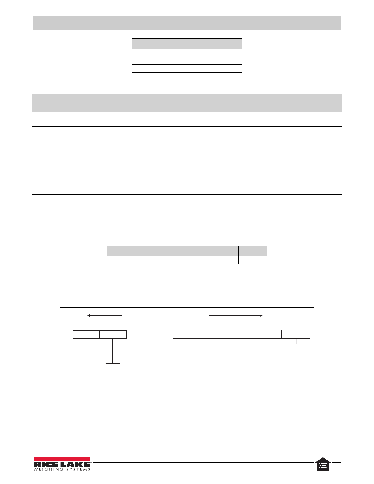
Examples of what is sent to the computer from the scale.
Figure 4-1. Escape Protocol Examples
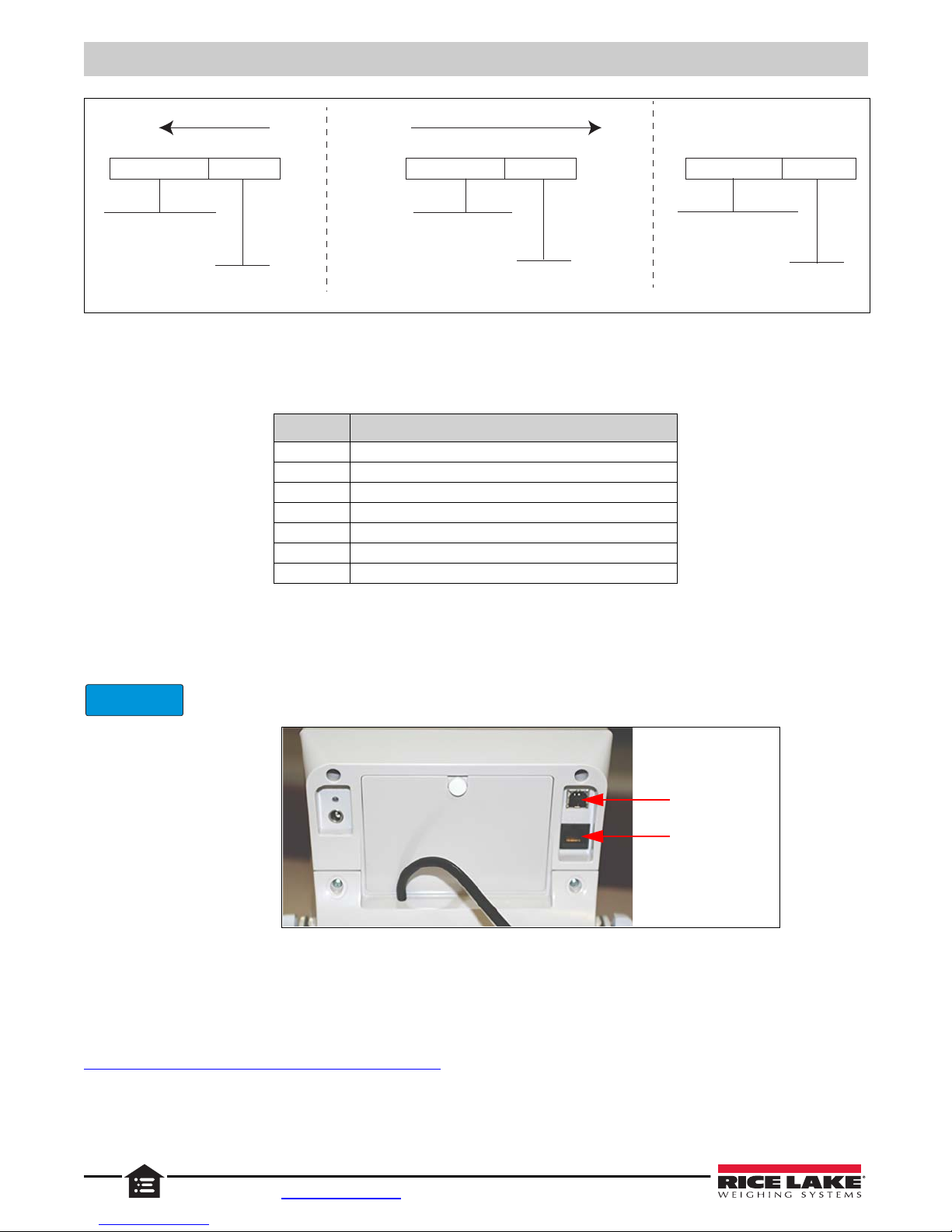
Examples of diagnosing battery request and responses.
©Rice Lake Weighing Systems ● All Rights Reserved 11
Page 16
160-10-7 Low-Profile Digital Physician Scale
Diagnose Battery Request Battery OK Response Battery Low Response
<ESC> ABAT <ESC> E
Diagnose battery
EOP
<SCALE> <PC>
direction of communication
<ESC> ZE4U <ESC> E
Battery is okay
(no errors)
EOP
<SCALE> <PC>
direction of communication
<ESC> ZE4L <ESC> E
Battery is very low
(Unstable)
EOP
IMPORTANT
USB
RS-232 Connection
Figure 4-2. Battery Requests
4.3 Maintenance Protocol
Maintenance protocol commands are described in Table Table 4-4..
Command Definition
R Reboot
V Firmware ID + development version
W Current weight
ACurrent AD
Z Zero the scale
F Show flash values (used for the first flash process)
L USB On/Off (not available on USB communication
Table 4-4. Maintenance Protocol Commands
4.4 USB Connection
The scale can be connected to a PC using a USB connection and a USB cable.
Always use medical grade isolators for USB and RJ45 when connected to non-medical equipment, or
when other medical equipment is connected to patient during procedure..
Connecting software and downloads should be addressed by an IT professional, and can vary depending on th e computer
platform used. Basic information on USB driver installation using Windows
as an example.
A USB driver can be downloaded from the Rice Lake Weighing Systems website at:
https://www.ricelake.com/resources/software-firmware
Figure 4-3. USB and RS-232 Connection Ports
®
is described in the following steps and serves only
1. Click on Software.
12 Visit our website www.RiceLake.com
Page 17
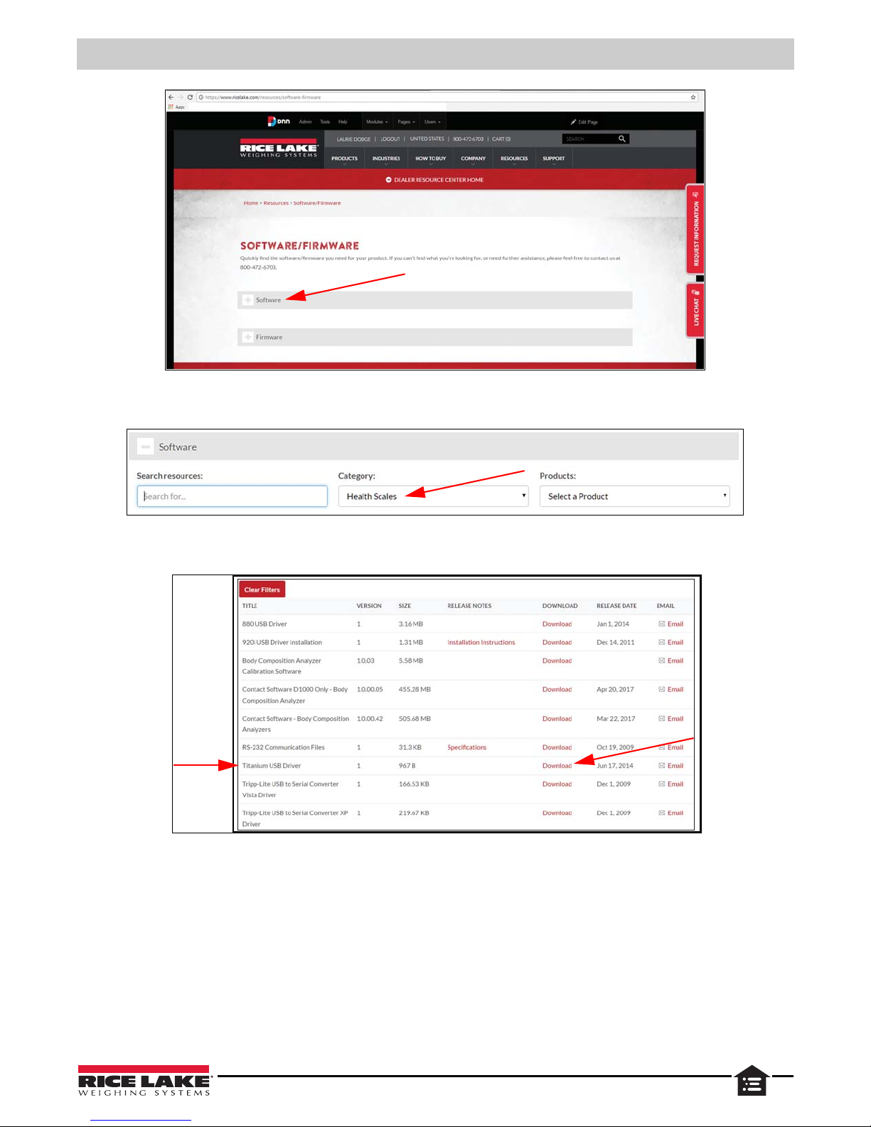
Figure 4-4. Software/Firmware Page
2. From the category drop down, select Health Scales.
Communications
Figure 4-5. Software Download Page
3. Locate the Titanium USB Driver. Click on Download to open and download the driver to a local computer.
Figure 4-6. Example of Drivers List Page
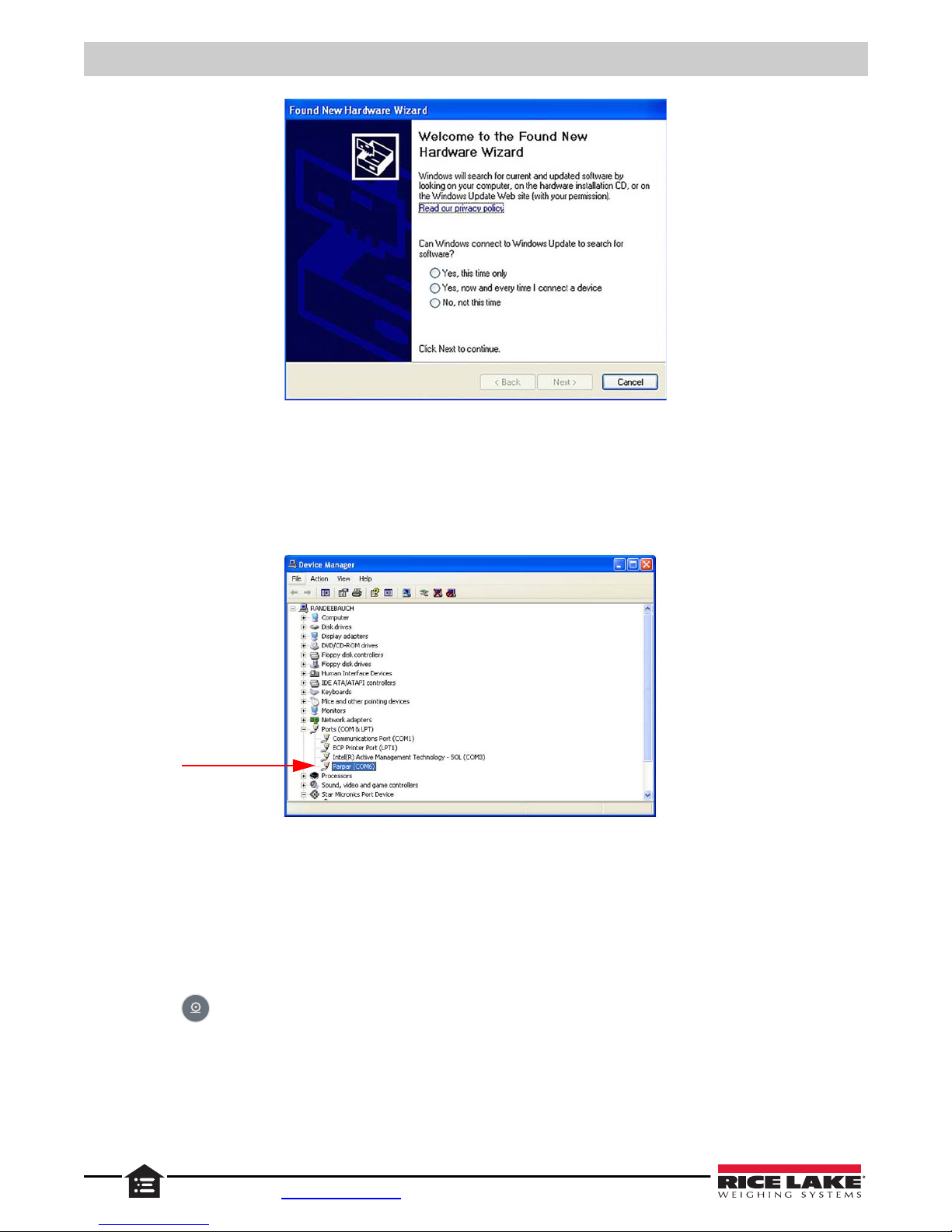
4. When the USB cable is connected to the indicator and the scale is turned on, the Found New Hardware Wizard
displays. After reading the privacy policy, select prompts to navigate through the software install process.
©Rice Lake Weighing Systems ● All Rights Reserved 13
Page 18
160-10-7 Low-Profile Digital Physician Scale
Figure 4-7. Hardware Wizard Menu
5. Select No, not this time and click Next.
6. Select Install the software automatically and select
Next. A file transfer screen displays as the file downloads and
installs to the computer.
7.
Click on
Finish when the completion screen displays.
8. To verify the installation, the driver can be viewed in the device manager of the computer.
9. To configure a printer using the USB driver, open the software driver Parpar in the device manager (Figure 4-8). The
port assigned to that driver is displayed.
10. Ensure the USB cable is properly connected and the unit is on.
11. Open and connect a terminal em ulation progr am, such as Hypert erminal, via the USB driver. Sele ct the port a ssigned
to the software driver Parpar to establish a port. The terminal emulation program is necessary to view information
transmitted from the indicator to the PC.
12. Press
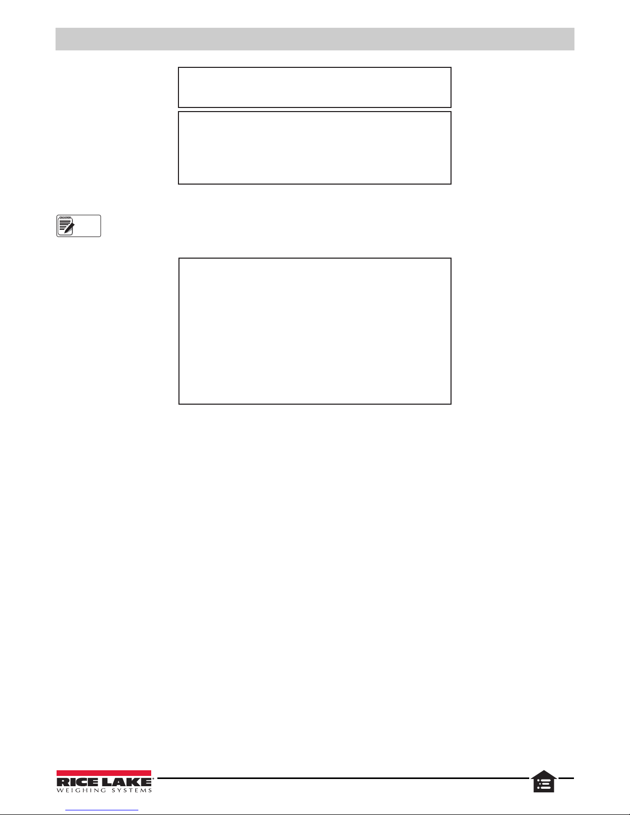
14 Visit our website www.RiceLake.com
. The following example tickets print.
Figure 4-8. Device Manager
Page 19
Communications
GROSS WEIGHT
199.8 lb
TARE WEIGHT
0.0 lb
PATIENT HEIGHT
6ft 00.0in
PATIENT B.M.I.
27.1
NET WEIGHT
199.8 lb
PATIENT WEIGHT 199.8 lb
Note
PATIENT WEIGHT
<CR>
<LF>
199.8 lb
<CR>
<LF>
<CR>
<LF>
<CR>
<LF>
<CR>
<LF>
<CR>
<LF>
<CR>
<LF>
Figure 4-9. Example Tickets
A single print ticket has four spaces after PATIENT WEIGHT, one space between the weight value and units (lb), and
seven <CR><LF> after.
Figure 4-10. IT Example (IT Information Only)
©Rice Lake Weighing Systems ● All Rights Reserved 15
Page 20
160-10-7 Low-Profile Digital Physician Scale
IMPORTANT
4.5 Optional Bluetooth
®
Many of the Rice Lake Medical Scales now have Bluetooth capability. Use the following instructions for the Bluetooth setup on
these scales. Bluetooth technology is a wireless technology for connecting health and fitness devices because it’s simple,
secure and everywhere. Bluetooth allows the transfer of data from the scale wirelessly to Bluetooth-enabled devices such as
cell phones, tablets, PDA or PCs.
Due to the vast number of Bluetooth devices on the market and the large number of software packages
available, there are many ways to pair and connect to the scale.
The steps used to pair the scale will vary, depend ing on the device/sof tware be ing used. The sca le is set up to be di scovera ble
at all times.
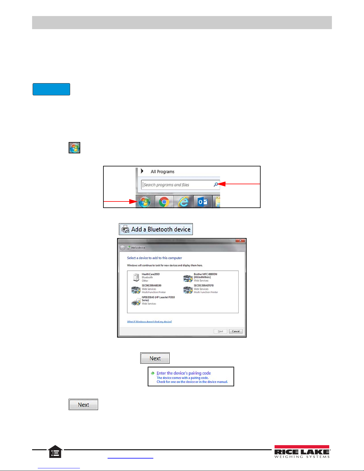
1. Power on the indicator.
2. Ensure the Bluetooth device is on. The flag icon display on the indicato r.
3. Press . The programs menu displays.
4. Type add into the search bar at the bottom.
Figure 4-11. Search Bar
5. Under Control Panel select . The Add a Device window opens.
Figure 4-12. Select Device
6. Select a Bluetooth device and press .
7. Select Enter the device’s pairing code.
8. Enter the device’s pairing code (4829) in the text box. Check black circle displays next to the selected device.
9. Press . This device has been successfully added to this computer displays.
16 Visit our website www.RiceLake.com
Page 21
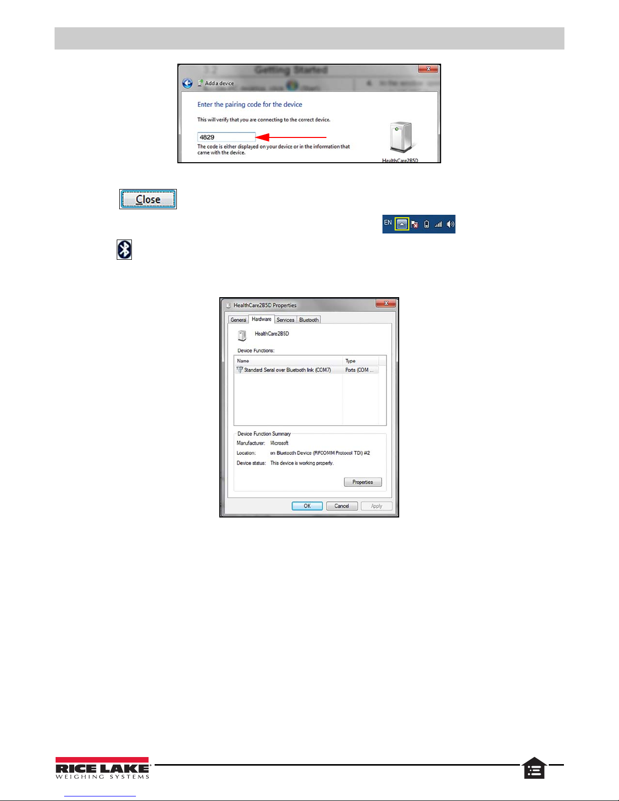
Figure 4-13. Pairing Code
10. Press .
11. Press the Show Hidden Icons arrow at the right side of the Task bar.
12. Press to open.
13. In the Properties window, right-click on the device icon and select Properties.
14. Select the Hardware tab to check the correct Comm and then click OK to confirm that.
Communications
15. Choose any communication terminal in order to send commands through the Bluetooth communication.
Once pairing is successfully completed, a bond will be formed between the two devices, enabling those two devices to connect
to each other.
Figure 4-14. Hardware Tab
©Rice Lake Weighing Systems ● All Rights Reserved 17
Page 22
5.0 Configuration
BMI
ENTER
ENTER
ENTER
BMI
ENTER
ENTER
ENTER
ENTER
ID
TEST
RLD VER A2D VALUE BAT
USER DONE
Scale configuration is used to set parameters and their values.
5.1 Scale Navigation
Use the buttons on the front panel to navigate through the menus and parameters
5.1.1 Change Parameters
• Press to scroll through the menus and/or parameters
• Press to enter a displayed menu and/or parameter
• Press or to scroll through values
• Press to save the displayed selection and move to the next parameter
5.1.2 Enter Numbers
• Press to enter parameter value
• Press or to increment/decrement numbers
• Press to move to the next digit
• Press to save value and move to the next parameter
5.1.3 Save and Return to Main Menu
• When a parameters selection/value is correct, press . The next parameter displays.
• When all parameters selections/values are correct,
SAVE displays
• Press . DONE displays.
• Press to save settings and return to weigh mode.
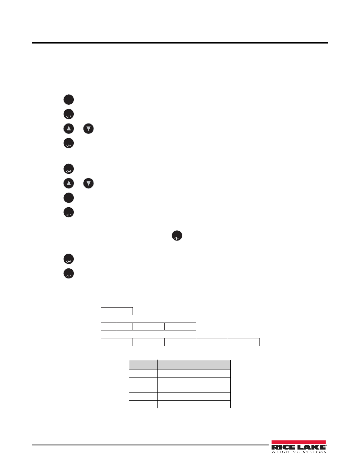
5.2 Test Menu
This menu is read only.
Parameter Description
RID Internal ID number
VER Development internal sub version
A2D Raw weight data
VALUE Processed weight in live display
BAT Relative raw battery value
Figure 5-1. Test Menu
Table 5-1. Test Menu Parameters
18 160-10-7 Low-Profile Digital Physician Scale Operatio n
Page 23
To enter this menu:
ENTER
ENTER
ENTER
BMI
BMI
ENTER
ID
TEST
USER DONE
BAUD
96
1152
48
576
384
288
144
192
TOFF
5
3
4
2
1
0
8
9
7
LIVE
OFF
ON
MAIN
OFF
ON
TARE
OFF
ON
ANTIP
OFF
ON
SAVE
ENTER
ENTER
BMI
ENTER
1. Press to turn on the indicator. START displays.
2. Press and hold until
3. Press .
4. Press .
TEST displays.
RLD and it’s value flashes.
ID and it’s value flashes.
5. Press to scroll through the menu items.
6. When
TEST displays again, press . DONE displays.
5.3 Press . The indicator will continue with the self test and finish in the weigh mode.User Menu
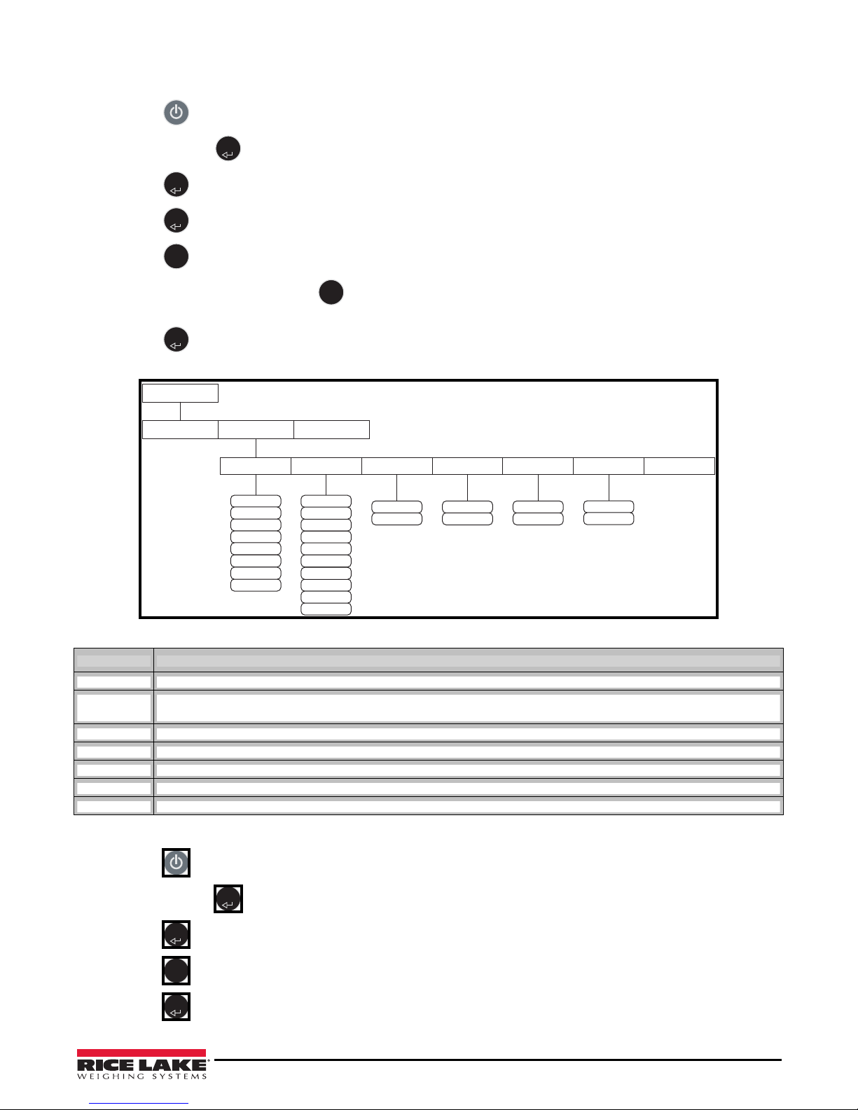
The User Menu allows a user to set the baud, auto off time and turn several other functions on or off.
Parameter Description
BAUD Baud Rate – set required baud rate; selections: 96 (default), 48, 1152, 576, 384, 288, 192, 144; end zeros are not displayed
TOFF
Auto Off Timer – turns unit after the set number of minutes; 0-9 minutes; 0 = always on; default: 5 min
battery power only, does not work if using an external power supply
LIVE Live Weighing – xxxxxxxxxxxx; default: OFF
MAIN Communication Protocal – xxxxxxxxxxxx; default: OFF
TARE Tare – xxxxxxxxxxxx; default: OFF
ANTIP – xxxxxxxxxxxx; default: OFF
SAVE Saves settings and returns to upper level
To enter this menu:
1. Press to turn on the indicator. START displays.
2. Press and hold until
3. Press .
TEST displays.
4. Press to scroll to
5. Press .
BAUD and it’s value flashes.
ID and it’s value flashes.
USER.
6
Figure 5-2. User Menu
Configuration 19
Page 24
6. Press to scroll through the menu items.
BMI
ENTER
ENTER
ENTER
ENTER
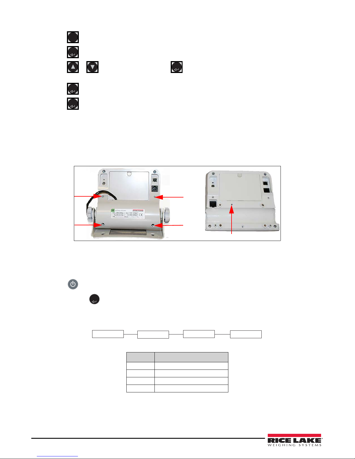
Setup Switch Location
ENTER
DEFCALIBPROG
DONE
7. Press to edit a parameter setting.
8. Press or to select the setting and press to save the setting and move to next parameter. When all
parameters have been set,
SAVE displays.
9. Press .
DONE displays.
10. Press . The indicator will continue with the self test and finish in the weigh mode.
11.
5.4 Setup Mode
Accessing the configuration menus require breaking the seals (Class III) and removing the back cover.
Figure 5-3. Back of Indicator
Use the following steps to enter into setup mode.
1. Ensure the scale is off.
2. Remove the back plate by loosening the four screws as shown in Figure 5-3.
3. Press to turn on the indicator. START displays.
4. Press and hold until
ID and the ID value flash.
5. Use a small non-conductive tool to press the setup switch.
5.4.1 Setup Mode Main Menu
20 160-10-7 Low-Profile Digital Physician Scale Operatio n
PROG displays.
Figure 5-4. Setup Mode Menu
Parameter Description
Program Setup configuration
Calibration Calibration settings
Default Reset all settings to factory default
Done Returns to weigh mode
Table 5-2.
Page 25
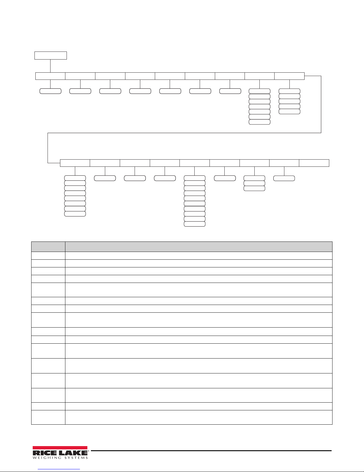
5.4.2 Programming Mode
PROG
FULL
LOAD G-CAL G-LOC
ASTRT ARW
SAL ROUND DISP
value value value value value value value
0.2
1.0
0.5
2.0
10.0
5.0
0.1
00000
0.00
0.0
0.000
0.0000
BAUD ATOL ALEN ATOUT TOFF SPACE UNITS OP SAVE
value value value value
P00-0
KG & LB
KG
5
3
4
2
1
0
8
9
6
7
96
1152
48
576
384
288
144
192
LB
The Programming Mode allows setup of the indicator to determine how the scale reads the weight and displays output.
Figure 5-5. Programming Menu Layout
Parameter Description
FULL Full Capacity – enter value of the scale capacity; default: 2500 kg
LOAD Load – weight applied during calibration; default: 160.0 kg NOTE: can also be changed in the calibration menu
G-CAL ........ default: 00000
G-LOC ............... default: 00000
ASTART
ARW Auto Reweigh – restarts the weight algorithm if the weight changed by more than this value; default: 2.0 kg
SAL Semi Auto Live – interval between weight displays during the algorithm process; default: 0.5
ROUND
DISP
BAUD Baud Rate – set required baud rate; selections: 96 (default), 48, 1152, 576, 384, 288, 192, 144; end zeros are not displayed
ATOL
ALEN
ATOUT
TOFF
SPACE Space – number of new lines after print; default: 7
UNITS
Auto-Start – weight process start limit; maximum (full capacity)/10; determines when the weight algorithm starts (when the ---- is displayed), below this value the scale displays live weight; default: 2.0 kg
Scale Resolution – display toggles between a numeric value and
selections: 0.1 kg (default), 0.5, 1, 2, 5, 10, 20, 0.2
Decimal Point – display toggles between a numeric value and
Algorithm Initial Tolerance – display toggles between a numeric value and
value above 255 (max) does not allow indicator to proceed and returns to the previous value
Algorithm Initial Exponent – display toggles between a numeric value and ALEN; default: 8;
Value above 10 (max) does not allow indicator to proceed and returns to the previous value.
Algorithm Maximal Exponent – display toggles between a numeric value and DISP; default: 10;
Values above 15 (max), does not allow indicator to proceed and returns to the previous value.
Auto Off Timer – turns unit after the set number of minutes; 0-9 minutes; 0 = always on; default: 5 min
battery power only, does not work if using an external power supply
Units – select the unit of measure; selections: LB, KG, KG/LB (default)
NOTE: When indicator is set to LB or KG, toggling between them is not available in the weighing mode.
Table 5-3. Program Mode Parameters
ROUND; decimal point location is set to the DISP parameter;
DISP; default: 00000
ATOL; default: 10;
Configuration 21
Page 26
Parameter Description
ENTER
DEFCALIBPROG
DONE
NO
YES
ENTER
ENTER
BMI
BMI
ENTER
ENTER
BMI
ENTER
Binary options:
• OP0 — Live weighing options (0=disable, 1=enable)
• OP1 — Communication protocol (0=ESC, 1=maintenance)
• OP2 — BMI menu (0=disable, 1=enable)
OP
SAVE Saves settings and returns to upper level
• OP3 — RTC power (0=disable, 1=enable)
• OP4 - Semi-Auto-Live — (0=disable, 1=enable)
• OP5 - Full calculation — (0=spatial, 1=multiply by (0=disable, 1=enable
• OP6 - Tare - (0=disable, 1=enable
• OP7 - Bat type — (0=d ry batteri es, 1=rechargeable batteries)
• OP8 — OIML mode - (0=d isable, 1=enable
Table 5-3. Program Mode Parameters (Continued)
To enter the program menu:
1. Enter the setup mode. See Section 5.4 on page 20.
2. With
3. Using the navigation instructions in Section 5.1 on page 18, set all
PROG displayed, press .
PROG parameters.
5.5 Default Menu
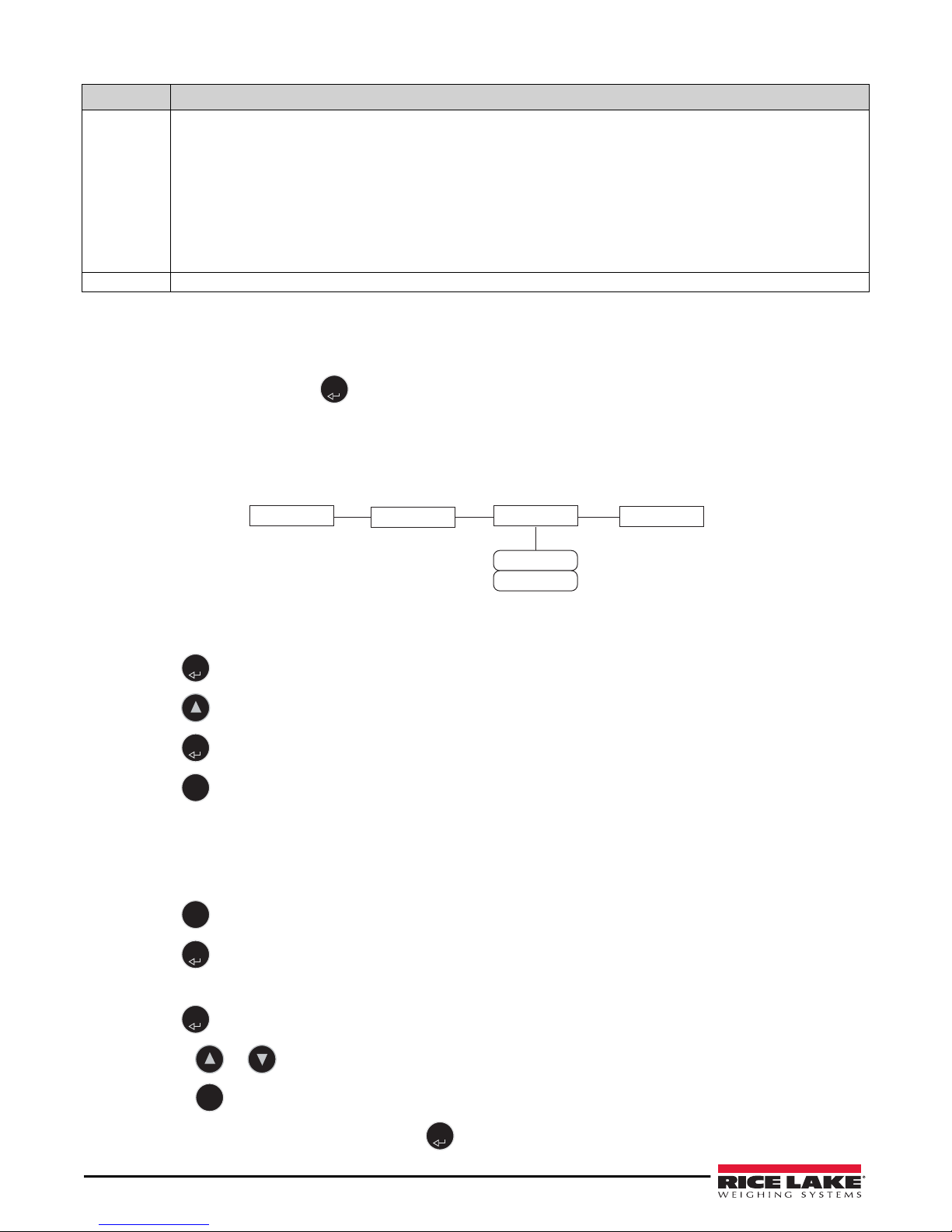
The default menu is used to return the scale to the original factory settings. This will not change the calibration.
Figure 5-6. Default Menu
5.5.1 Set to Default
1. Press . NO displays.
2. Press . YES displays.
3. Press .
4. Press to return to main menu.
DONE displays.
5.6 Scale Calibration
To calibrate the scale:
1. Enter the setup mode. See Section 5.4 on page 20.
2. Press to scroll to
CALIB.
3. Press . A numeric value displays (weight to be used for calibration).
4. Only calibrate in LB.
5. Press
. The digit on the right flashes.
•Press or to change the value of digit.
•Press to move to the next digit.
• When the desired value is displayed, press . CLEAR displays.
22 160-10-7 Low-Profile Digital Physician Scale Operatio n
Page 27
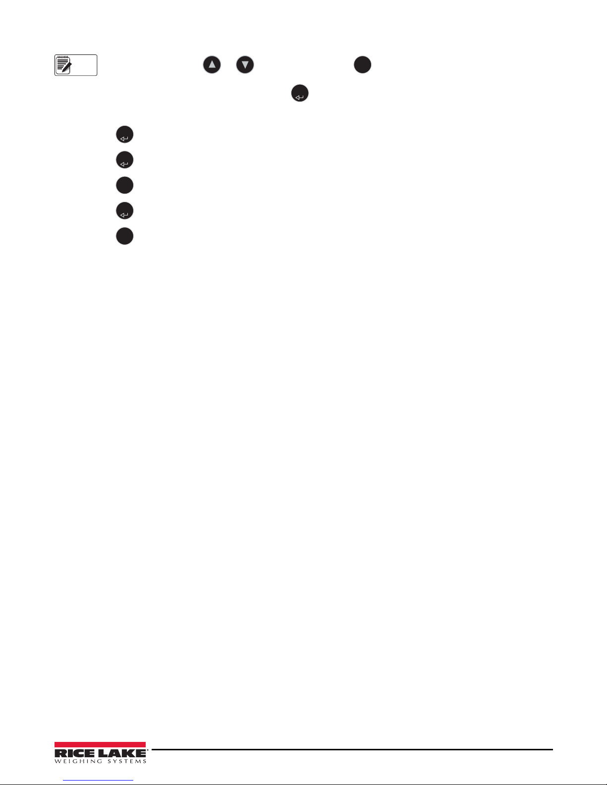
To quit calibration, press or . ABORT displays. Press to abort and return to upper level.
Note
BMI
ENTER
ENTER
ENTER
BMI
ENTER
BMI
6. Remove all weight from scale platform, then press . ===== displays.
7. When
8. Press .
9. Press .
10. Press three times to the top level
PUT and value flashes on display, put the weight on the platform.
===== and then Save displays.
DONE displays.
DONE parameter.
11. Press to return to weigh mode.
12. Press to exit calibration without changing zero or span of existing calibration.
Configuration 23
Page 28
6.0 Maintenance and Troubleshooting
IMPORTANT
6.1 Maintenance
The following section provides instructions for maintaining and cleaning the Rice Lake line of scales.
Do not immerse the scale in cleaning or other liquid solutions.
Do not use Isopropyl alcohol or other solutions to clean the indicator display surface.
6.1.1 Basic Maintenance
Before using the scale and after periods of non-use, check the scale for proper operation and function. If the scale does not
operate correctly, contact a qualified service personnel.
Basic maintenance includes:
• Check the overall appearance of the entire scale for any obvious signs of da mage.
• Inspect the condition of the AC adapter cord for cracking, fraying or broken/bent prongs.
• Using an adapter that has been used elsewhere may cause issues with the scale.
• Change batteries on a regular interval. Leaving in for long periods of time can cause batteries to leak.
6.1.2 Cleaning
Proper care and cleaning is essential to ensure a long life of accurate and effective operation. Before beginning the cleaning
process, disconnect the scale from the AC power source.
• Clean all external surfaces with a clean, damp cloth or tissue.
• Mild soap and water solution may be used.
• Standing platform may be cleaned with Isopropyl alcohol
• Dry with a clean soft cloth.
6.2 Troubleshooting
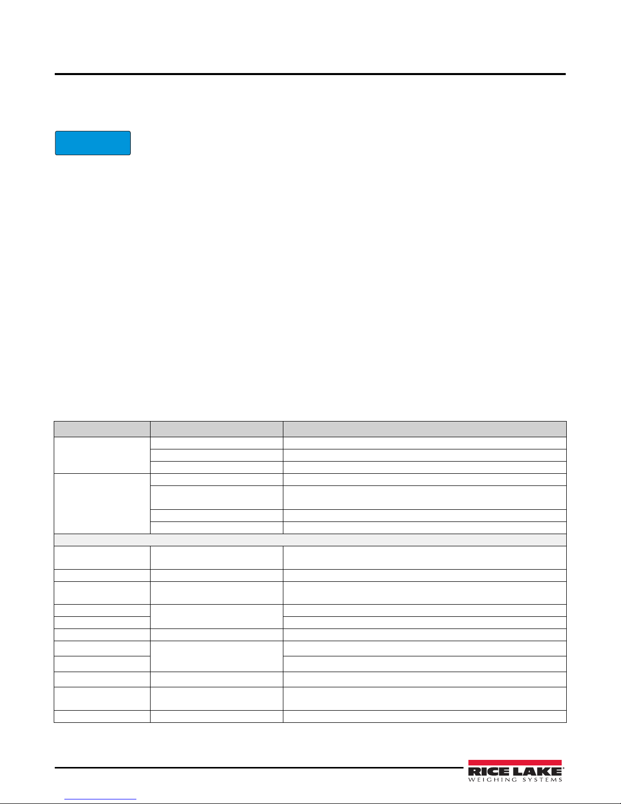
Refer to Table 6-1 to diagnose and correct failures prior contacting service personnel for assistance.
Symptom or Error Possible Cause Corrective Action
Dead battery Replace batteries or connect scale to a power source
Scale does not turn on
Questionable weight or the
scale does not zero
Displayed messages as detailed below.
STOP
LO Bat The batteries are low Replace the batteries
SAT
E06
E07 AD too low
E10 Overload Scale is overloaded; Remove load from scale
E4L
E4U
E11 CAL
Err 2 Low saturation state (low A/D)
Err 3 High saturation state (high A/D) See Err 2
Faulty electrical outlet Use a different electrical outlet
Bad power supply Replace AC adapter
External object interfering with scale Remove the interfering object from the scale
Display did not show 0.0 before
weighing
Scale is not level Ensure the scale is level and begin the weighing process again
Scale is out of calibration Check the weight with a known weight value
The load on the scale exceeds the
capacity of the scale
Damaged load cell cable
Possible wrong port
Identifier - ADC
BAT
Table 6-1. Troubleshooting Table
Help the patient off the scale, zero the scale and begin the weighing process again
Remove excess weight and use the scale according to the
manufacturer’s specifications
Replace load cell cable
Check ports
AD too high
Battery low but still usable
Battery low and unstable
Calibration Error
The load cell is not connected properly; Check the cables and mechanical connections; If the problem persists, replace the set of load cells
— recalibrate the scale again
— 1 bar left on the indicator display
— no bars left on the indicator display
24 160-10-7 Low-Profile Digital Physician Scale Operatio n
Page 29

Symptom or Error Possible Cause Corrective Action
6.3 Specifications
Power
Adapter Power 120 V/230 VAC adapter, NEMA 1-15 plug
Battery Power
Rechargeable (Class III) or
6 X 1.5AA (Non-Class III)
Battery Life 25 hours continuous; automatic power-off
can be configured
Data Communications
Connections RS-232 with RJ-45 jack, USB
Baud Rate 9600 (Default)
Bits 8; 1 stop bit
Parity None
Handshaking None
Environmental
Operating Temp 50 to +95°F (10 to 35°C)
Storage Temp 32 to 122°F (0 to 50°C)
Humidity 85% Relative Humidity
Capacity and Graduation
Floor Level Scale 550 lb x 0.2 lb (250 kg x 0.1kg)
Certifications and Approvals
RoHS Compliant
Dimensions
Platform Dimensions 14.4'' W x 14.4'' L x 1.65'' H
Err 6
Unstable weight
Cannot calibrate
Table 6-1. Troubleshooting Table
Check the load cells’ mechanical surroundings and ensure nothing touches them and
that the cables are properly welded
Maintenance and Troubleshooting 25
Page 30

7.0 Low Profile Digital Physician Scale Limited Warranty
Rice Lake Weighing Systems (RLWS) warrants that all RLWS equipment and systems properly installed by a Distributor or
Original Equipment Manufacturer (OEM) will operate per written specifications as confirmed by the Distributor/OEM and
accepted by RLWS. All systems and components are warranted against defects in materials and workmanship for two years.
RLWS warrants that the equipment sold hereunder will conform to the current written specifications authorized by RLWS. RLWS
warrants the equipment against faulty workmanship and defective materials. If any equipment fails to conform to these
warranties, RLWS will, at its option, repair or replace such goods returned within the warranty period subject to the following
conditions:
• Upon discovery by Buyer of such nonconformity, RLWS will be given prompt notice with a detailed explanation of the
alleged deficiencies.
• Individual electronic components returned to RLWS for warranty purposes must be packaged to prevent electrostatic
discharge (ESD) damage in shipment. Packaging requirements are listed in a publication, Protecting Your Components
From Static Damage in Shipment, available from RLWS Equipment Return Department.
• Examination of such equipment by RLWS confirms that the nonconformity actu ally exists, and was not caused by
accident, misuse, neglect, alteration, improper installation, improper repair or improper testing; RLWS shall be the sole
judge of all alleged non-conformities.
• Such equipment has not been modified, alte red, or changed by any person oth er than RLWS or its duly authorized repair
agents.
• RLWS will have a reasonable time to repair or replace the defective equipment. Buyer is responsible for shipping
charges both ways.
• In no event will RLWS be responsible for travel time or on-location repairs, including assembly or disassembly of
equipment, nor will RLWS be liable for the cost of any repairs made by others.
These warranties exclude all other warranties, expressed or implied, including without limitation warranties of merchantability or
fitness for a particular purpose. Neither RLWS nor distributor will, in any event, be liable for incidental or consequential
damages.
RLWS and buyer agree that RLWS’s sole and exclusive liability hereunder is limited to repa ir or replacement of such goods. In
accepting this warranty, the buyer waives any and all other claims to warranty.
Should the seller be other than RLWS, the buyer agrees to look only to the seller for warranty claims.
No terms, conditions, understanding, or agreements purporting to modify the terms of this warranty shall have any legal effect
unless made in writing and signed by a corporate officer of RLWS and the Buyer.
© Rice Lake Weighing Systems, Inc. Rice Lake, WI USA. All Rights Reserved.
RICE LAKE WEIGHING SYSTEMS • 230 WEST COLEMAN STREET • RICE LAKE, WISCONSIN 54868 • USA
26 160-10-7 Low-Profile Digital Physician Scale Operatio n
Page 31

Page 32

230 W. Coleman St. • Rice Lake, WI 54868 • USA
U.S. 800-472-6703 • Canada/Mexico 800-321-6703 • International 715-234-9171 • Europe +31 (0)26 472 1319
Rice Lake Weighing Systems is an ISO 9001 registered company.
© Rice Lake Weighing Systems Specifications subject to change without notice.
www.ricelake.com
PN 185558 Rev CAugust 18, 2017
 Loading...