

Riccar Radiance RAD.5 Service Manual
Service Manual for RAD.5 and Older Models

I. Common Issues .......................................................................... 2
Table of Contents
A. Direct Air Motor.................................................................................. 2
A.1. Direct Air Motor will not run. ................................................... 2
A.2. Direct Air Motor is making a squealing sound. ..................... 2
B. Full Bag Indicator (FBI) ..................................................................... 3
B.1. Full bag light will not come “ON”. .......................................... 3
B.2. Bag is full but the FBI did not come “ON”. ............................ 3
B.3. Bag is not full and the FBI light is on. .................................... 3
C. General Issues: ................................................................................. 4
C.1 Why does the dust cover gap open when the lower
motor is turned “ON”? ............................................................... 4
C.2. The vacuum does NOT run but the lights in the handle
switches are on. .......................................................................... 4
C.3. Identifying Models by PCB Layout or Belt Idler Assembly ... 5
II. Maintenance Procedures .......................................................... 6
A. Disassembly Instructions................................................................... 6
B. Removing the Brush Strips................................................................ 8
C. Replacing the Belt ............................................................................. 9
D. Replacing the LED Light Board ....................................................... 10
E. Replacing the Spring Assist Assembly ............................................ 10
F. Replacing the Main PC Board...........................................................11
G. Replacing the Clean Air Motor ........................................................ 12
H. Installing the Motor Cover ............................................................... 13
I. Removing and Replacing the Direct Air Motor .................................. 14
J. Replacing the Direct Air Motor Fan .................................................. 16
K. Replacing the Rear Wheels............................................................. 18
L. Replacing the Tilt Lock Pedal Spring ............................................... 18
III. General Troubleshooting ....................................................... 19
A. Vacuum has no power. .................................................................... 19
B. Direct Air Motor Will Not Run........................................................... 21
B.1. Direct Air Motor Will Not Run: No Headlights ............................ 21
B.2. Direct Air Motor Will Not Run: Headlights are on ...................... 22
C. Nozzle Suction Power is Weak ....................................................... 24
C.1. There is no suction at the hose ................................................. 24
C.2. There is no suction at the nozzle .............................................. 24
D. Excessive Vibration ......................................................................... 25
E. Agitator/brushroll Does Not Rotate .................................................. 25
F. Agitator/brushroll Jam Test .............................................................. 26
IV. Trouble Shooting - .4 and Older Models Only ...................... 27
A. Full Bag Indicator (FBI) Comes On Too Soon or Not At All ............. 27
B. Agitator/brushroll Jam Light Comes On Too Soon or Not At All ....... 28
V. Trouble Shooting - .5 and .6 Models Only ............................. 29
A. Direct Air Motor Starts But Shuts Off in 2 or 3 Seconds .................. 29
B. The Full Bag Indicator will ash On when the vacuum is shut Off. . 29
VI. Figures
A. Correct Handle Installation ................................................................ 4
B. PCB Layout and Belt Idler Assembly.................................................5
C. Location of Nozzle Cover Screws ..................................................... 6
D. Agitator/Brushroll Assembly .............................................................. 8
E. Belt Placement .................................................................................. 9
F. Clean Air Motor Wiring ..................................................................... 12
G. Ametek Clean Air Motor Wiring ....................................................... 12
H. Clean Air Motor Placement ............................................................. 12
I. Handle to Body Harness Connector ................................................. 19
J. Location of Winged Rocker Switch .................................................. 22
K. Location of Micro Switch .................................................................22
L. Proper Position for Tools Activation Dial/Rotational Valve Handle ... 23
M. Agitator/brushroll Jam Screw - FBI Screw Position ........................ 27
N. Handle Assembly ............................................................................ 30
O. Body Assembly ............................................................................... 31
P. Nozzle Assembly .............................................................................32
Q. Handle Wiring .................................................................................33
R. Main Body Wire Harness .5 and .6 Models ..................................... 34
S. Main Body Wire Harness .4 and Older Models ............................... 35
T. Description of Vacuum ..................................................................... 36

IMPORTANT SAFETY INSTRUCTIONS
When using or servicing any electrical appliance, basic precautions should always be
followed, including the following:
WARNING: To reduce the risk of re, electrical shock, or injury:
1. Do not leave vacuum unattended when plugged in. Unplug from outlet when not in use.
2. Turn off all controls before unplugging.
3. Do not attempt to service vacuum while plugged in.
4. Before handling PC board, discharge static electricity by using anti-static mat and
ground strap. If anti-static mat is not available, touch a metal object that is grounded and
only handle PC board by outside edges.
WARNING: ELECTRIC SHOCK COULD OCCUR IF USED OUTDOORS OR ON WET SURFACES.

I. Common Issues
A. Direct Air Motor
A.1. Direct Air Motor will not run.
Check the following:
1. The main switch must be “ON” and the oor/carpet switch must be in the carpet position.
2. The tools activation dial/rotational valve handle must be in the tools “OFF” position.
3. The vacuum must be out of the upright position (controlled by the wing rocker switch) unless the nozzle cover is off.
4. The clean air motor must have 12 to 18 volts going to the PC board via the blue/yellow tap wire.
5. The headlights should be on. This assures that the fuses on the PC board are working and there is power in the tap wire. (See
Figure B. PCB Layout and Belt Idler Assembly)
NOTE: All the above conditions must be met on .4 and older models. .5 and newer models must also have the belt installed
belt for the hall sensor to work, other wise the direct air motor will come on for 2 to 3 seconds then shut “OFF”.
A.2. Direct Air Motor is making a squealing sound.
Check for the following conditions:
1. The motor has been changed and the seals are out of place or the motor is not seated properly.
2. The bearings are damaged.
3. Hair or thread is wrapped around the motor shaft and the bearing under fan.
071807 I. Common Issues
2

B. Full Bag Indicator (FBI)
B.1. Full bag light will not come “ON”.
The full bag indicator is controlled by temperature. As the bag lls, the air ow is restricted causing the motor to work harder building up
heat in the motor compartment. At a set point, this heat build up causes the FBI to illuminate. It may take up to 2 minutes for the FBI
light to illuminate. If the airow is not completely blocked off, the temperature may not reach the point needed to turn on the FBI light.
Additionally, if the bag has been lled with uffy type material such as carpet ber, the air ow may not be restricted enough to cause the
motor to build up heat.
To test the FBI system:
1. The air ow must be completely blocked off.
2. Place the tool activation dial/rotational valve handle to the tools “ON” position.
3. Blocking off the hose the FBI light should illuminate with in 2 minutes.
B.2. Bag is full but the FBI did not come “ON”.
Check the bag for content. If the bag is full of carpet ber or other uffy material the air ow may not be restricted enough to cause the
motor to heat up and the light to illuminate.
B.3. Bag is not full and the FBI light is on.
The FBI light will illuminate if the pores of the HEPA bag become clogged with a ne powder type substance, such as drywall dust.
This is the most common reason for the light to illuminate.
071807 I. Common Issues
3
C. General Issues:
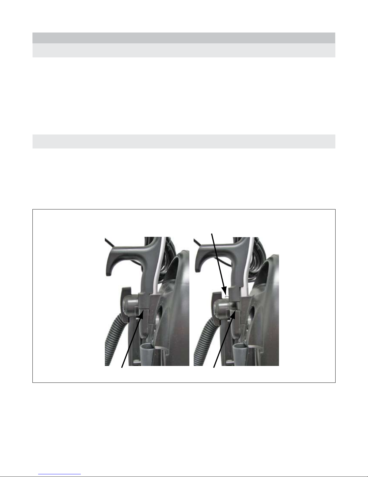
Correctly Installed Handle
Incorrectly Installed Handle
Remove handle screw before installing handle
C.1 Why does the dust cover gap open when the lower motor is turned “ON”?
The direct air motor pulls more air into the dust compartment than the clean air motor can push out. This could be caused by the
following:
1. The nozzle is not sitting on the oor; therefore the airow is not restricted and will push the cover open.
2. The HEPA lter may be clogged, causing back pressure.
3. The bag inlet seal may be torn allowing air to bypass the HEPA bag, increasing the airow so the clean air motor cannot relieve all
the pressure.
C.2. The vacuum does NOT run but the lights in the handle switches are on.
The lights in the handle main power switch will come on any time the power cord is plugged into an outlet and the main power switch is
turned “ON”. The light in the carpet/oor switch will be on any time there is power to the handle and both the main power switch and the
carpet/oor switch are turned “ON.”
1. If the lights are on in the handle switch and vacuum won’t run, check the thermal reset switch.
2. If the vacuum still won’t run, make sure the handle is installed correctly. (See Figure A. Correct Handle Installation)
3. If the vacuum still won’t run see section III. General Troubleshooting, A. Vacuum Has No Power
Figure A. Correct Handle Installation
071807 I. Common Issues
4
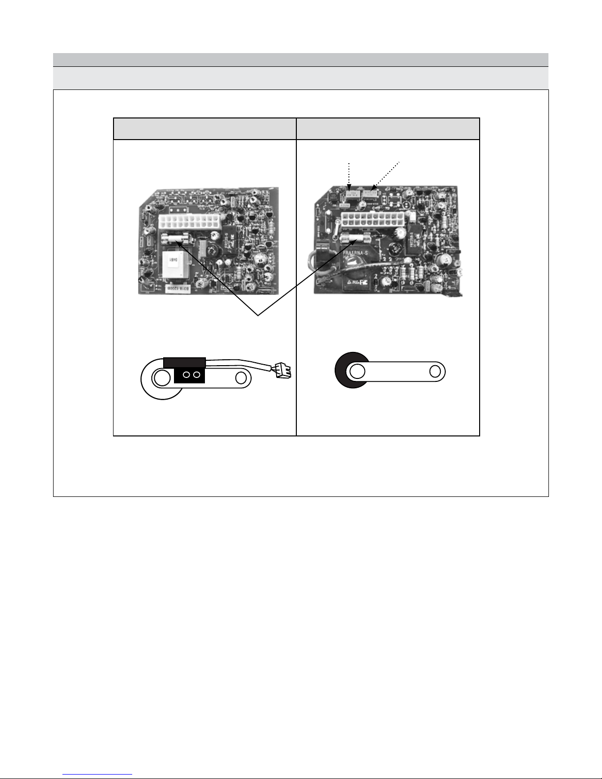
Belt Idler Assembly Belt Idler Assembly
PC Board PC Board
.5 and .6 .4 and older
Brush Roll AFI
Fuse
C. General Issues - continued
C.3. Identifying Models by PCB Layout or Belt Idler Assembly
Figure B. PCB Layout and Belt Idler Assembly
NOTE: The PC Boards in the .5 and .6 do not have adjustment pods because they have a hall sensor on the belt idler assembly.
071807 I. Common Issues
5
II. Maintenance Procedures
1
2
3
4
5
A. Disassembly Instructions
A. Step 1.
1. Remove the handle and dust cover.
2. Place the vacuum face down on the bench.
3. Remove the base plate by removing the 2 (two) screws.
4. Remove the agitator/brushroll.
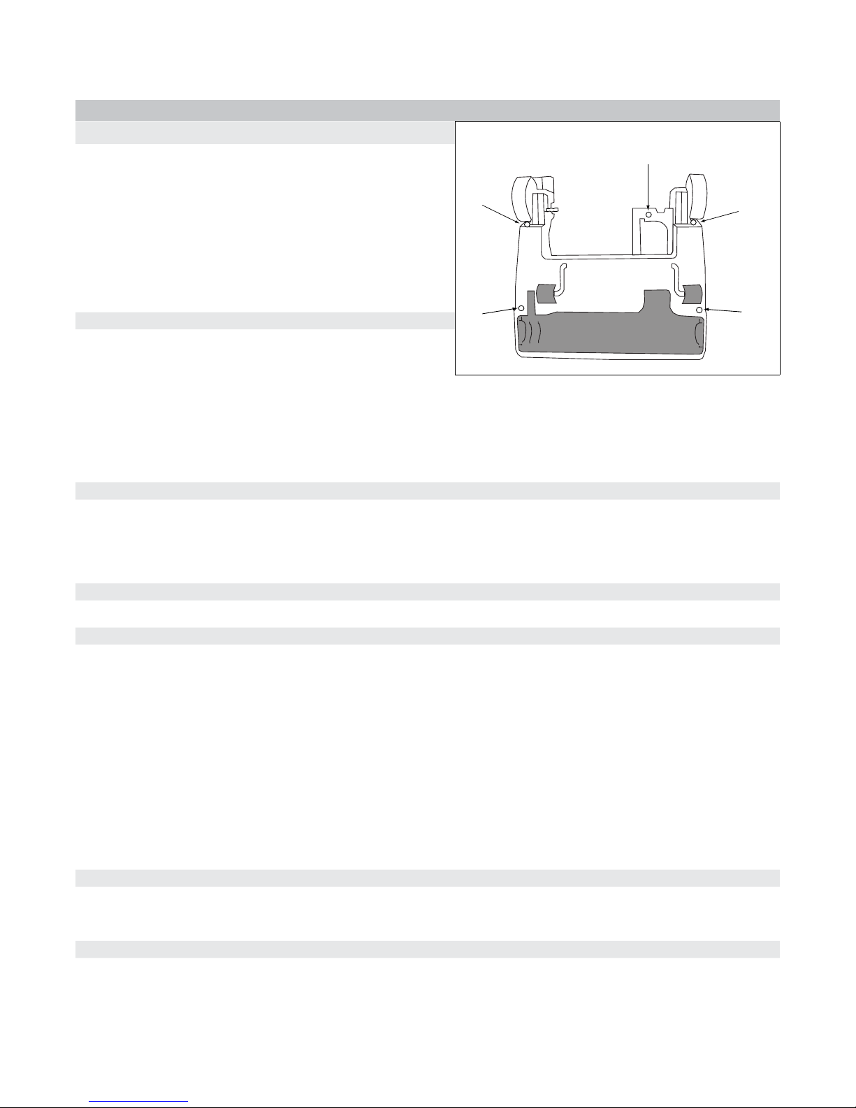
5. Remove the 5 (ve) mounting screws on the underside of the
nozzle base tray. (See Figure C. Location of Nozzle Cover
Screws)
A. Step 2. Removing the Back Path and Cover
1. Remove 1 (one) screw in the tools activation dial/rotational
valve handle and 8 (eight) screws on the back path and hose.
2. Remove tools activation dial/rotational valve handle and back path cover.
3. Remove 1 (one) screw from the micro switch and then the remaining 13 (thirteen) screws in the back cover.
4. Remove the back cover allowing the micro switch to slide through the slot in cover.
5. Remove the tool clips.
A. Step 3.
NOTE: Skip to A. Step 4. if wiring harness is NOT being changed.
Figure C. Location of Nozzle Cover Screws
A. Step 4.
A. Step 5.
A. Step 6.
1. If wire inlet seal (foam seal where the wire goes through the dust compartment) is installed, remove it at this time.
2. Remove the wire harness connector from the dust compartment and the micro switch from the wiring harness.
Turn the vacuum over, depress handle release, and lay at. Remove the nozzle cover.
WARNING - If the vacuum is not in the upright position before continuing with the next step, injury may occur or vacuum
may be damaged.
1. Set the vacuum in the upright position and remove the 2 (two) screws from the spring assist bar.
2. Lay the vacuum at. Remove the 3 (three) screws from the direct air motor inlet duct cover, and 1 (one) screw from each of
the wire strain relief (2 each) .
3. Remove the belt.
4. Remove 3 (three) screws from the idler cover and spring.
5. Disconnect the light lead connector from the light board (disconnect the ground wire if necessary).
6. Remove the 2 (two) screws from each of the pivot brackets.
1. Lift the dust compartment up out of the nozzle base tray assembly.
2. Remove the pivot bushings and the direct air motor inlet seal from the dust compartment.
A. Step 7.
1. Remove the 4 (four) screws holding the motor cover on the dust compartment.
2. Lift up on the motor cover and set it aside. -continue on next page
071807 II. Maintenance Procedures
5

A. Disassembly Instructions - Continued
A. Step 8.
1. .4 models and older - Remove the direct air motor by lifting up and rotating, and then disconnect the leads.
2. .5 models and newer - Remove screw holding direct air motor in place and lift up.
A. Step 9.
Remove the clean air motor motor and disconnect the leads.
A. Step 10.
NOTE: Complete A. Step 10 and A. Step 11 only if wiring harness is being changed.
1. Remove the screw from the PC board.
2. Disconnect the wiring harness and remove the PC board.
3. Remove the screw in the metal plate and the metal plate from the dust compartment.
A. Step 11.
1. Remove the 2 (two) screws that hold the thermal reset switch in place.
2. Remove the winged rocker switch from dust compartment and disconnect the leads.
3. Slide the wire harness through the hole in the back of the dust compartment
4. Raise the corner of the main body seal and remove the wiring harness.
071807 II. Maintenance Procedures
6

B. Removing the Brush Strips
1
1
2
2
3
3
4
5
5
5
B. Step 1.
1. Remove the base plate by removing the 2 (two) screws.
2. Remove the agitator/brushroll.
3. If the belt un-loops itself from the motor shaft, the nozzle cover may need to be removed by removing the 5 (ve) mounting
screws on the underside of the nozzle base tray. (See Figure C. Location of Nozzle Cover Screws.)
B. Step 2.
Remove the rubber end cap covers. Figure D. Agitator/Brushroll Assembly
B. Step 3.
Remove the nuts on each end of the agitator/brushroll with a 7/16 socket driver. Figure D. Agitator/Brushroll Assembly
B. Step 4.
Slide off the end caps. Figure D. Agitator/Brushroll Assembly
B. Step 5.
Pry off the belt pulley with a standard screwdriver. Figure D. Agitator/Brushroll Assembly
B. Step 6.
Slide off the brush strips and replace. Figure D. Agitator/Brushroll Assembly
B. Step 7.
Line up the belt pulley and push on.
B. Step 8.
Reinstall the steel end caps and nuts and tighten with a socket.
B. Step 9.
Reinstall the rubber end cap covers.
Figure D. Agitator/Brushroll Assembly
1 Agitator/brushroll End Cap Cover
2 1/4-28 Locking Hex Nut
3 Agitator/brushroll Steel End Cap
4 Agitator/brushroll Pully
5 Brush Strips
071807 II. Maintenance Procedures
7
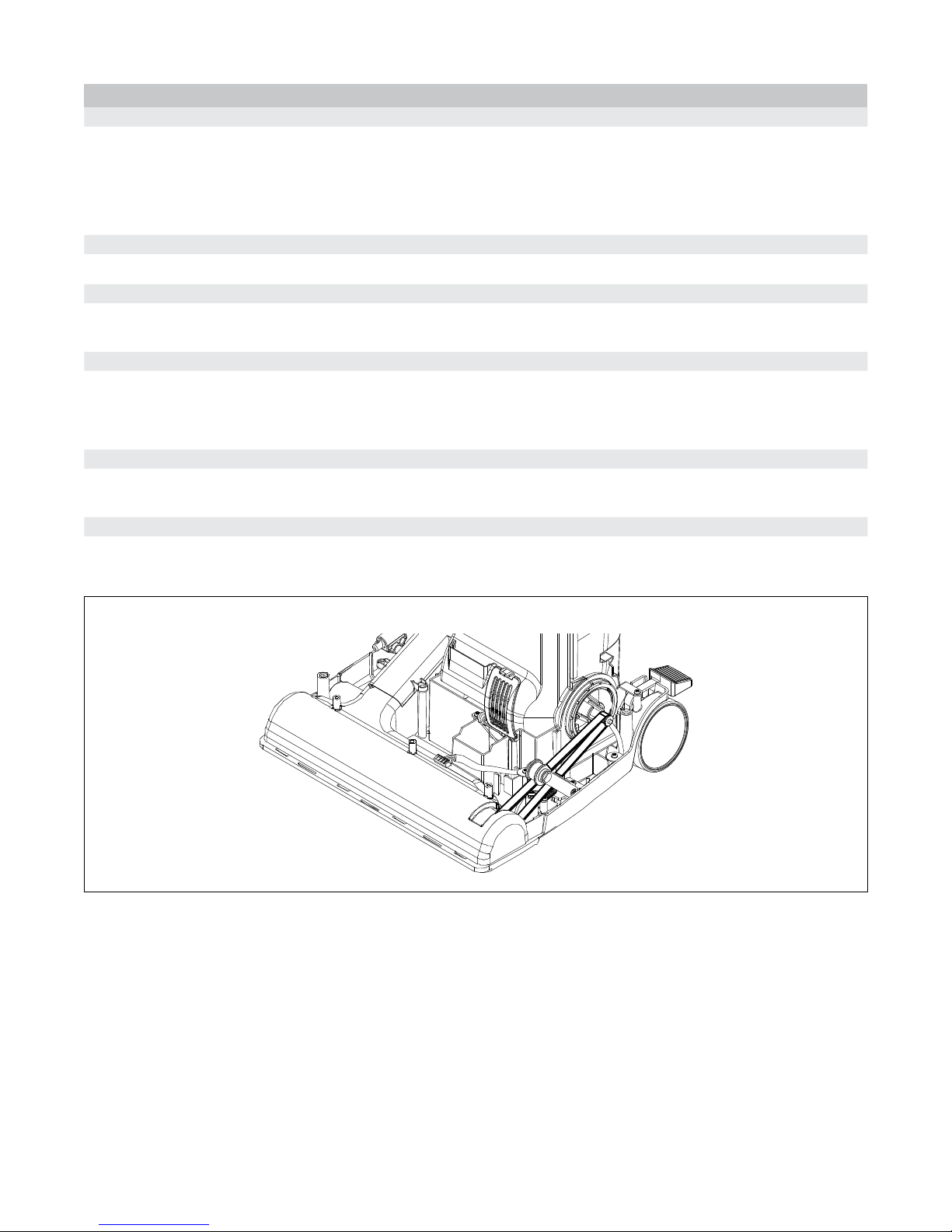
C. Replacing the Belt
C. Step 1.
1. Remove the base plate by removing the 2 (two) screws.
2. Remove the agitator/brushroll.
3. Remove the 5 (ve) mounting screws on the underside of the nozzle base tray. (See Figure C. Location of Nozzle Cover
Screws)
C. Step 2.
Discard the broken belt.
C. Step 3.
Note the layout of the idler assembly and the motor drive pulley. (See Figure E. Belt Placement) Loop the new belt over the
motor drive pulley then continue directing the belt under the idler pulley. Insert the belt into the nozzle base tray.
C. Step 4.
Turn the vacuum over and pull the belt into the nozzle base tray. Loop belt around the agitator/brushroll making sure the ribs
of the belt line up with the ribs on the agitator/brushroll.
NOTE: Ensure the felt seals are installed in the nozzle base tray.
C. Step 5.
Insert the agitator/brushroll into the nozzle base tray making sure the rubber end cap covers t precisely into the ribbed mounts
on the nozzle base tray. Rotate the agitator/brushroll a few times to ensure the belt is mounted correctly.
C. Step 6.
Reinstall the base plate and the nozzle cover.
NOTE: If the agitator/brushroll runs backwards, check the belt to ensure it is not twisted.
Figure E. Belt Placement
071807 II. Maintenance Procedures
8

D. Replacing the LED Light Board
D. Step 1.
Remove the 5 (ve) mounting screws on the underside of the nozzle base tray. (See Figure C. Location of Nozzle Cover
Screws)
D. Step 2.
Remove the 3 (three) screws holding the light board onto the nozzle base tray - the middle screw may have the ground wire
attached.
D. Step 3.
Disconnect the wire connector and replace the light board.
D. Step 4.
Install the 3 (three) screws into LED light board attaching it to the nozzle base tray. NOTE: If the ground wires are on the wiring
harness or the LED light board, place the ground wires under middle screw.
D. Step 5.
Attach the wiring harness connector to the LED light board connector.
D. Step 6.
Reinstall the nozzle cover.
E. Replacing the Spring Assist Assembly
WARNING - If the vacuum is not in upright position injury may occur or vacuum may be damaged.
- Always wear safety glasses during repair.
E. Step 1.
Remove the 5 (ve) mounting screws on the underside of the nozzle base tray. (See Figure C. Location of Nozzle Cover
Screws)
E. Step 2.
With the vacuum locked in the upright position, remove the 2 (two) screws from the bracket holding the spring.
E. Step 3.
Ensure that the spring has been disconnected. Lay the vacuum at to remove the spring mount by pressing the ramped black
tab of the spring mount with a at screwdriver while pulling the spring out-ward.
E. Step 4.
Remove the bracket and mount from the old spring and attach to the new spring.
E. Step 5.
Push the spring mount into the motor cover until the mount snaps into place.
E. Step 6.
Lock the vacuum in the upright position.
E. Step 7.
Insert the two screws in to the spring bracket.
E. Step 8.
Reinstall the nozzle cover.
071807 II. Maintenance Procedures
9
 Loading...