

Page 1
IN4004
NETWORK COMPATIBLE RELAY / CURRENT SENSOR COMBOS
RIBMNWX2401B-BC
2.75˝ Track Mount BACnet® MS/TP Network Relay
Device; One Binary Output (20 Amp Relay SPDT
+ Override); Two Binary Inputs (One Current
Sensor 0.25 - 20 Amp, Relay Load Sensing & One
Dry Contact Binary Input), 24 Vac/dc or 120 Vac
Power Input, Optional End of Line Resistor (EOL)
Included.
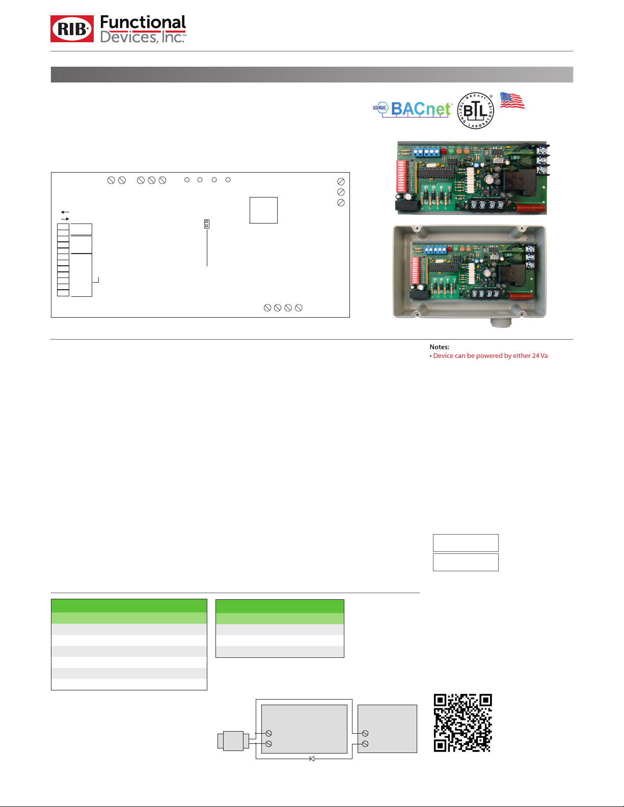
}
REF
A(–)
B(+)
}
1
0
Relay
Override
Baud
Rate
LSB
1 2 3 4 5 6 7 8 9 10 11 12
MSB
SPECIFICATIONS
# Relays & Contact Type:
Expec
Operating Temperature:
Humidity Range:
Network Communication:
Current Sensor Status:
Binary Input Status:
Housing Rating:
Relay Override Switch:
Network Media:
DIP SWITCHES* BAUD RAT E
8 9 10
0 0 0
0 0 1
0 1 0
0 1 1
1 0 0
1 0 1
All other combinations=9600 baud
Dry Contact
Binary Input
MS/TP ADDRESS
ted Relay Life:
Operate Time:
Relay Status:
Dimensions:
Track Mount:
Approvals:
Gold Flash:
Terminations:
Polarity:
Baud Rate:
MSTP
Connect Jumper for EOL.
Disconnect for no
terminating resistor.
One (1) SPDT Continuous Duty Coil
10 million cycles minimum mechanical
-30 to 140° F
5 to 95% (noncondensing)
18ms
Green LED
Red LED On = Activated
Pink LED On = Activated
Pink LED On = Activated
6.00˝ x 2.75˝ x 1.75˝ (RIBMNWX2401B-BC)
4.28˝ x 7.00˝ x 2.00˝
with .75˝ NPT Nipple (RIBTWX2401B-BC)
MT212-6 Mounting Track Provided
UL Listed, UL916, C-UL
UL Listed, NEMA 1, C-UL, CE Approved,
UL Accepted for Use in Plenum,
Also available NEMA 4 / 4X
No
DIP Switch Control
Twisted Pair 22-24AWG, shielded recommended
Functional Devices product installed at both ends
of the MS/TP network – Use 120 Ω end of line
resistors. All other cases – Follow instructions from
the device installed at the end of the
MS/TP network.
Network is polarity sensitive
9600, 19200, 38400, 57600, 76800, 115200 (DIP
Switch Selectable)
9600
19200
38400
57600
76800
115200
RIBTWX2401B-BC
Enclosed BACnet® MS/TP Network Relay Device;
One Binary Output (20 Amp Relay SPDT + Override); Two Binary Inputs (One Current Sensor
0.25 - 20 Amp, Relay Load Sensing & One Dry
Contact Binary Input), 24 Vac/dc or 120 Vac
Power Input, Optional End of Line Resistor (EOL)
Included.
Contacts
Internal
Current
Red LED=Relay Status
Pink LED=Current Sensor Status
Green LED=Network Communication
* 0 = Open ; 1 = Closed
** Device must be powered for override
Sensor
Pink LED=Binary Input Status
Low Voltage
Power Input
High Voltage
}
Comm
24 Vac/dc
Neutral
Contact Ratings:
20 Amp Resistive @ 277 Vac
20 Amp Ballast @ 277 Vac
16 Amp Electronic Ballast @ 277 Vac (N/O)
10 Amp Tungsten @ 120 Vac (N/O)
1110 VA Pilot Duty @ 277 Vac
770 VA Pilot Duty @ 120 Vac
2 HP @ 277 Vac
1 HP @ 120 Vac
Power Input:
24 Vac/dc ; 120 Vac ; 50/60 Hz
Power Input Ratings:
105 mA @ 24 Vac
78 mA @ 24 Vdc
105 mA @ 120 Vac
Current Sensor Range:
0.25 - 20 Amps
Threshold xed at .25 Amps.
DIP SWITCHES* RELAY STATE**
11 12
1 0
X 1
0 0
RIBMNWX2401B-BC or RIBTWX2401B-BC
}
Power Input
}
120 Vac
Auto
Override on
Override o
COM
N/O
N/C
• Dry contact binary
input is a general
purpose input that is
not tied t
internally. Can be used
with any dry contact
swit
as a current sensor,
to report back to the
network.
o the relay
ching device, such
Half-Wave Device
Made in USA
Meets
“Buy American”
of ARRA 2009
Notes:
• Device can be powered by either 24 Vac/dc or
120 Vac, but not both.
• Order NEMA 4 housing by adding “-N4” to end
of model number. (RIBTWX2401B-BC-N4)
• Order with grey lid by adding “-GY” to end of
model number. (RIBTWX2401B-BC-GY)
• Order NEMA 4 housing with grey lid by adding
“-N4-GY” to end of model number.
(RIBTWX2401B-BC-N4-GY)
• When connecting 24 Vac to both the RIB(s) and a
half-wave device, damage to device can occur.
Option 1: Use separate transformers for each
device. Option 2: Add diode between devices,
see Option 2 note below. ^^
BACnet® Details:
• MS/TP Address & Baud Rate must be set prior to
power up via DIP switches.
Device ID will default to 277XXX where XXX is
•
the MS/TP Address.
Examples:
MS/TP Address - 004
Device ID - 277004
MS/TP Address - 121
Device ID - 277121
•
Device ID can be changed via network
command. Once changed, it will no longer
default to 277XXX. (MS/TP Address & Device ID
must be unique.)
• This model utilizes: BO 1 (Relay output),
BI 1 (Dry contact binary input), BI 2 (Internal
current sensor input)
• Device Instance changed via Object Identier
Property of Device Object
• PIC Statement available on website.
http://www.functionaldevices.com/pdf/
pics/RIBxWX240xB-BC_PICS.pdf
Or scan QR code with your smart phone.
24 Vac
^^ Option 2:
24 Vac/dc
Com
24 Vac
Com
Add diode on 24 Vac power (Com) interconnection
between devices. Band on diode faces towards RIB(s).
071417
 Loading...