

Page 1
RELAYS
24 Vac/dc
nvo HVACTemp
NV1
nci Max SendT1
nci Min Send T1
nci Min Delta
Closed Loop Actuator
nvi Value
NV1
nvo Value Fb
NV2
nci Default
nci Max Receive T
Open Loop Sensor Object
(Binary Output) (Binary Input)
* Temperature Sensor
nvo Value
NV1
nci Invert
nci Max Send T
nci Min Send T
Node Object
nvi Request nvo Status
NV1 NV2
nvo HVACTemp
NV1
nci Max SendT1
nci Min Send T1
nci Min Delta
Closed Loop Actuator
nvi Value
NV1
nvo Value Fb
NV2
nci Default
nci Max Receive T
Open Loop Sensor Object
(Binary Output) (Binary Input)
* Temperature Sensor
nvo Value
NV1
nci Invert
nci Max Send T
nci Min Send T
nvo HVACTemp
NV1
nci Max SendT1
nci Min Send T1
nci Min Delta
Open Loop Sensor Object
* Temperature Sensor
nvo Value
NV1
nci Invert
nci Max Send T
nci Min Send T
nvo HVACTemp
NV1
nci Max SendT1
nci Min Send T1
nci Min Delta
* Temperature Sensor
24 Vac/dc
IN4004
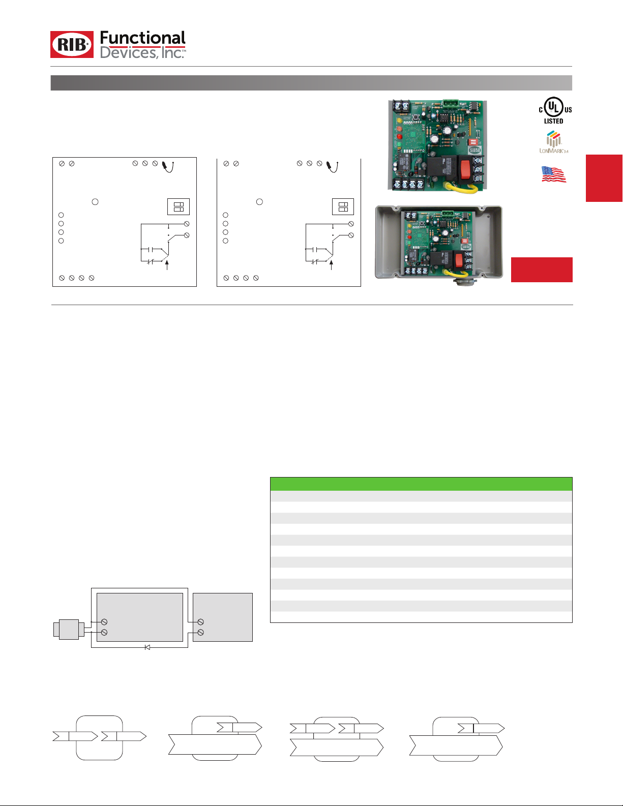
NETWORK COMPATIBLE RELAYS
RIBMW24SB-LNT2
4.00˝ Track Mount LonWorks® Twisted-Pair FT-10
Network Three I/O Device; One Binary
Output (20 Amp Relay SPST + Override), One
Binary Input (Dry Contact, Class 2); Precon® Type 2
Thermistor Input; 24 Vac/dc Power Input
Connect Precon® 10K
@ 77℉ (25℃), Type 2,
Model 24 (or equivalent)
to Thermistor terminals:
+5 Vdc and Analog-In. Set
DIP switch to 5V (see below.)
Class 2
Dry Contact
Binary Input
Service Button
YELLOW LED = Service
PINK LED = Binary Input Status
RED LED = Relay Activated
GREEN LED = Network Status
LON
LON
Com
SPECIFICATIONS
# Relays & Contact Type:
Expected Relay Life:
Operating Temperature:
Humidity Range:
Operate Time:
Green LED:
Yellow LED:
Pink LED:
Dimensions:
Track Mount:
Approvals:
Housing Rating:
Gold Flash:
Override Switch:
Transceiver Type:
Transceiver Compatibility:
Functional Blocks:
Downloadable Files:
RIBMW24SB-LNT2, RIBTW24SB-LNT2,
RIBMW24SB-LNT3 or RIBTW24SB-LNT3
24 Vac
^^ Option 2:
Add diode on 24 Vac power (Com) interconnection
between devices. Band on diode faces towards RIB(s).
Red LED:
Channel:
24 Vac/dc
Com
+ 5 V
AI Com
Analog-In
(typically not used)
5 V
10 V
1 2
OPEN
CLOSED
OPEN
AUTO
Selectable
Jumper Wire
One (1) SPST Continuous Duty Coil
10 million cycles minimum mechanical
-30 to 140° F
5 to 95% (noncondensing)
18ms
Network Status
Relay Status
Service Status
Binary Input Status
4.00˝ x 4.00˝ x 1.50˝ (RIBMW24SB-LNT2)
4.28˝ x 7.00˝ x 2.00˝ with .75˝ NPT Nipple
(RIBTW24SB-LNT2)
MT4-4 Mounting Track Provided
FCC, LonMark®
UL Listed, UL916, C-UL
UL Listed, NEMA 1, C-UL, CE Approved,
UL A
ccepted for Use in Plenum,
Also available NEMA 4 / 4X
No
Yes
TP/FT-10
FT5000 Smart Transceiver
FT3120 / FT3150, FTT-10 / FTT-10A, and
LPT-10 / LPT-11 Tranceivers
0000 Node Object
0004 Closed Loop Actuator Object
0001 Open Loop Sensor Object
1040 Temperature Sensor
PDF, XIF, APB, VSS and NXE
available on website.
RIBTW24SB-LNT2
Enclosed LonWorks® Twisted-Pair FT-10 Network
Three I/O Device; One Binary Output (20 Amp
Relay SPST + Override), One Binary Input (Dry
Contact, Class 2); Precon® Type 2 Thermistor
Input; 24 Vac/dc Power Input
Connect Precon® 10K
@ 77℉ (25℃), Type 2,
Model 24 (or equivalent)
to Thermistor terminals:
Class 2
Service Button
YELLOW LED = Service
PINK LED = Binary Input Status
RED LED = Relay Activated
GREEN LED = Network Status
LON
Half-Wave Device
24 Vac
Com
DIP switch to 5V (see below.)
Dry Contact
Binary Input
LON
+5 Vdc and Analog-In. Set
Com
Contact Ratings:
20 Amp Resistive @ 277 Vac
20 Amp Ballast @ 120/277 Vac (N/O)
10 Amp Ballast @ 120/277 Vac (N/C)
Not rated for Electronic Ballast
10 Amp Tungsten @ 120 Vac (N/O)
1110 VA Pilot Duty @ 277 Vac
770 VA Pilot Duty @ 120 Vac
2 HP @ 277 Vac
1 HP @ 120 Vac
Power Input Ratings:
111 mA @ 24 Vac
81 mA @ 24 Vdc
Power Input:
24 Vac/dc ; 50/60 Hz ^
+ 5 V
AI Com
Analog-In
(typically not used)
5 V
10 V
CLOSED
OPEN
AUTO
Selectable
Jumper Wire
DESCRIPTION SNVT NAME SNVT TYPE
Command to open/close relay nvi Value SNVT_switch
Command status of relay nvo Value Fb SNVT_switch
Default state of relay on/o nci Default SNVT_switch
Communication timer nci Max Receive T SNVT_elapsed_tm
Status of Digital-In nvo Value SNVT_switch
Invert status of Digital-In nci Invert SNVT_lev_disc
Max time between updates nci Max Send T SNVT_elapsed_tm
Min time between updates nci Min Send T SNVT_elapsed_tm
T2 Thermistor input * nvo HVACTemp SNVT_temp_p
Max time between Temperature updates nci Max Send T1 SNVT_elapsed_tm
Min time between Temperature updates nci Min Send T1 SNVT_elapsed_tm
Min change in Temperature before updates nci Min Delta SNVT_temp_p
The relay will go to the default state when the communication timer times out. Setting the timer value
to zero will cause the communication to never time out.
It is recommended to put a value in nci Max Send T to ensure the RIB re-synchronizes itself on the network after power loss. It is the responsibility of the user to ensure this value does not cause conicts in
network trac. (No value = No “heartbeat” updates / no re-sychronization; Low Value = Many updates
but may cause many trac collisions; High value = Few updates but many less collisions.)
1 2
OPEN
Made in USA
Meets
“Buy American”
of ARRA 2009
THERMISTOR
INPUT
Notes:
• Order with P1 option by adding “-P1” to end of model
• Normally Open or Normally Closed selected by yellow
• Order NEMA 4 housing by adding “-N4” to end of model
• -35 to 100°C
• When connecting 24 Vac to both the RIB(s) and a
• Can be used with Precon® Type 3 Thermistor Input. Use
he P1 option is pre-programmed to allow dry
number. T
contact binary input to command the relay. Contact closure
on the BI will activate relay.
jumper wire.
number. (RIBTW24SB-LNT2-N4)
range in one degree steps. -36°C indicates
below range, 101°C indicates above range.
half-wave device, damage to device can occur.
Option 1: Use separate transformers for each device.
Option 2: Add diode between devices, see Option 2
note below. ^^
sux “-LNT3” instead of “LNT2” when ordering. Thermistor
not included.
071717
 Loading...