

Page 1
RELAYS
FAN SAFETY ALARM CIRCUITS
of ARRA 2009
RIBMNLB-6NO/-4NO/-2NO
2.75” Track Mount AHU Fan Safety Alarm and General Purpose Logic Circuit, 24 Vac Power Input, 2/4/6 Alarm Inputs
all with N/O Outputs
R1 OUT
N/O
R1
Alarm
Input
Indicators
R1 R1 COM R2 R2 COM R3 R3 COM R4 R4 COM R5 R5 COM R6 R6 COM
CLOSED
OPEN
Isolated Dry Contact Outputs,
Each Rated 1.5A @ 24 Vac/dc
R2 OUT
R3 OUT
R4 OUT
N/O
N/O
R2
R3
21
CLOSED
OPEN
43
R5 OUT
N/O
N/O
R4
R5
CLOSED
65
OPEN
3A Total Sourced
from 24 Vac/dc Input or Dry
Contact (Jumper Selectable)
R6 OUT
R7
POLE 1
N/O
R6
Master
Relay
R7
COM 24V
R7
POLE 2
Master Alarm
Indicator
24V Power
Legend for
Jumper Selection
=
Dry
=
24V
Made in USA
Meets
“Buy American”
Alarm
Input 1
Alarm
Input 2
Alarm
Input 3
Alarm Input
Bypass Switches
Alarm
Input 4
Alarm
Input 5
SPECIFICATIONS
Expected Relay Life:
Operating Temperature:
Humidity Range:
Operate Time:
Power Input:
Alarm Status:
Dimensions:
Track Mount:
Approvals:
Gold Flash:
Override Switch:
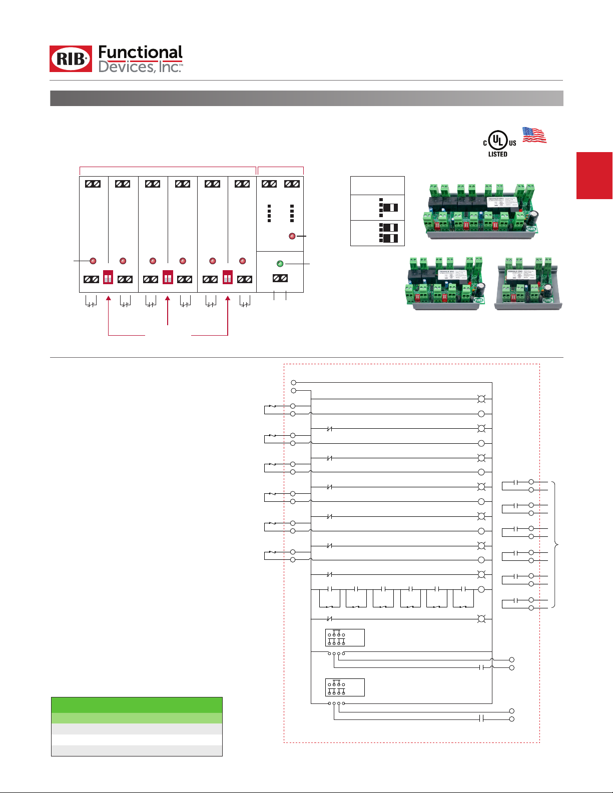
Models RIBMNLB-6NO, RIBMNLB-4NO, and RIBMNLB-2NO are
simply devices that combine a common relay-logic function into
a small, easy-to-install, and less expensive form.
A master relay will open if any one of the normally-closed (N/C)
inputs open. There are six, four, or two inputs depending on
the model chosen. LED status of all inputs, the master relay,
and power input is provided. Bypass of un-used inputs is also
provided. The RIBMNLB series is provided with mounting track
for mounting in user-provided electrical enclosures.
The master relay has two general-purpose outputs: both can
be jumper selected at 24 V (sourced from input) or dry contact.
The most common application is an Air Handling Unit (AHU)
fan-safety-shutdown where the master relay is used to shutdown
the fan. Contact closure outputs are provided so that a DDC
controller can determine the cause of a shutdown.
Notes:
• RIBMNLB-6NO has six Alarm Inputs and one Master Alarm.
• RIBMNLB-4NO has four Alarm Inputs and one Master Alarm.
• RIBMNLB-2NO has two Alarm Inputs and one Master Alarm.
• This is a half wave device. When connecting 24 Vac to both this
device and a full-wave device, damage to device can occur.
10 million cycles minimum mechanical
-30 to 140° F
5 to 95% (noncondensing)
8ms
4 Amp max. @ 24 Vac/dc ; 50-60 Hz
LED On = Activated
6.200˝ x 2.750˝ x 1.750˝ (RIBMNLB-6NO)
4.600˝ x 2.750˝ x 1.750˝ (RIBMNLB-4NO)
3.000˝ x 2.750˝ x 1.750˝ (RIBMNLB-2NO)
MT212-6 Mounting Track Provided (RIBMNLB-6NO)
MT212-4 Mounting Track Provided
(RIBMNLB-4NO, RIBMNLB-2NO)
UL Listed, UL916, UL864, C-UL
No
No
SELECTION GUIDE
Model# Inputs
RIBMNLB-6NO 6
RIBMNLB-4NO 4
RIBMNLB-2NO 2
MT212 Mounting Track
MT212 Mounting Track
MT212 Mounting Track
Alarm
Input 6
4A Max
Input 1
Input 2
Input 3
Input 4
Input 5
Input 6
24 Vac Input Power
Com
24 V
R1-3
R2-3
R3-3
R4-3
R5-3
R6-3
R2-1
R1-1
Input 2
Input 1
Bypass
Bypass
R7-3
R7-1 Output Conguration Jumper
Dry Contact
Wet Contact
P1 P2 P3 P4
R7-2 Output Conguration Jumper
Dry Contact
Wet Contact
P5 P6 P7 P8
R3-1
Input 3
Bypass
RIBMNLB-6NO
R4-1
Input 4
Bypass
R5-1
Input 5
Bypass
24 Vac Preset Indicator
R1 Alarm Indicator
R2 Alarm Indicator
R3 Alarm Indicator
R4 Alarm Indicator
R5 Alarm Indicator
R6 Alarm Indicator
R6-1
Input 6
Bypass
R7 Alarm Indicator
R7-1
R7-2
R1
R2
R3
R1-2
R4
R5
R6
R7
R2-2
R3-2
R4-2
To DDC Controller
R5-2
R6-2
071417
 Loading...