

Page 1
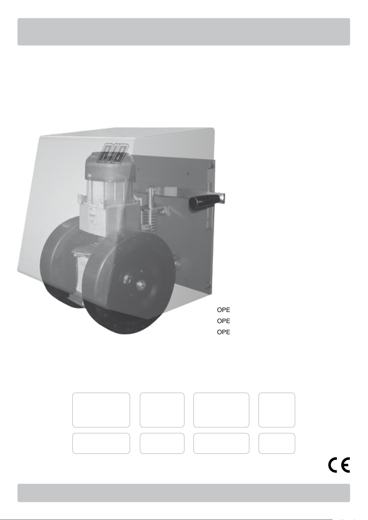
R50
OPERATORE PER PORTONI INDUSTRIALI
OPERATEUR POUR PORTAILS INDUSTRIELS
OPERATOR FOR INDUSTRIAL DOORS
TORANTRIEB FÜR INDUSTRIETORE
Operatore
Operateur
Operator
Torantrieb
R50 230V 50/60Hz AA21580
Alimentazione
Alimentation
Power Supply
Stromspannung
Peso max cancello
Poids maxi portail
Max gate weight
Max Torgewicht
2000 kg / 4460 lbs
codice
code
code
code
ITALIANO pag. 04 / FRANÇAIS pag. 14 / ENGLISH page 24 / DEUTSCH pag. 34
Page 2

IMPORTANT SAFETY INSTRUCTIONS FOR
G
THE INSTALLATION
B
WICHTIGE SICHERHEITS ANLEITUNGEN FÜR
D
DIE INSTALLATIONEN
- ATTENTION FOR THE SAFETY OF THE PEOPLE IT IS IMPORTANT
TO FOLLOW ALL THE INSTRUCTIONS.
FOLLOW ALL INSTALLATION INSTRUCTIONS
1° - This handbook is exclusively addressed to the specialized
personnel who knows the constructive criteria and the protection
devices against the accidents for motorized gates, doors and
main doors (follow the standards and the laws in force).
2° - The installer will have to issue to the final user a handbook in
accordance with the EN 12635.
3° - Before proceeding with the installation, the installer must forecast
the risks analysis of the final automatized closing and the safety
of the identified dangerous points (following the standards EN
12453/EN 12445).
4° - The wiring harness of the different electric components external to
the operator (for example photoelectric cells, flashlights etc.) must
be carried out according to the EN 60204-1 and the modifications
to it done in the point 5.2.2 of the EN 12453.
5° - The possible assembly of a keyboard for the manual control of the
movement must be done by positioning the keyboard so that the
person operating it does not find himself in a dangerous position;
moreover, the risk of accidental activation of the buttons must be
reduced.
6° - Keep the automatism controls (push-button panel, remote control
etc.) out of the children way. The controls must be placed at a
minimum height of 1,5m from the ground and outside the range
of the mobile parts.
7° - Before carrying out any installation, regulation or maintenance
operation of the system, take off the voltage by operating on the
special magnetothermic switch connected upstream it.
THE RIB COMPANY DOES NOT ACCEPT ANY RESPONSIBILITY
for possible damages caused by the non observance during the
installation of the safety standards and of the laws in force at present.
- ACHTUNG FÜR DIE SICHERHEIT DER PERSONEN IST ES WICHTIG,
DASS ALLE ANWEISUNGEN GENAU AUSGEFÜHRT WERDEN
ALLE INSTALLATIONSANLEITUNGEN BEFOLGEN
1° - Diese Betriebsanleitung dient ausschließlich dem
Fachpersonal, welche die Konstruktionskriterien und die
Sicherheits-Vorschriften gegen Unfälle für Tore, Türen und
automatische Tore kennt (geltende Normen und Gesetze
beachten und befolgen).
2° - Der Monteur muss dem Endkunde eine Betriebsanleitung in
Übereinkunft der EN12635 überreichen.
3° - Vor der Installierung muss für die automatische Schließung
und zur Sicherheitsgewährung der identifizierten kritischen
Punkte, eine Risiko Analyse vorgenommen werden mit der
entsprechenden Behebung der identifizierten, gefährlichen
Punkte. (die Normen EN 12453/EN 12445 befolgend).
4° - Die Verkabelung der verschiedenen externen elektrischen
Komponenten zum Operator (z.B. Fotozellen, Blinker etc.) muss
nach EN 60204-1 ausgeführt werden, Änderungen davon nach
Punkt 5.2.2 der EN 12453.
5° - Die eventuelle Montage einer Schalttafel für den manuellen
Bewegungsbefehl muss so angebracht werden, dass der
Benutzer sich nicht in einer Gefahrenzone befindet, und dass,
das Risiko einer zufälligen nicht gewollten Aktivierung von
Schaltern gering ist.
6° - Alle Steuerungselemente (Schalttafel, Fernbedienung etc.)
gehören nicht in Reichweite von Kindern. Die Kommandos
müssen min. 1,5 m ab Boden und außerhalb des Aktionsbereiches
der mobilen Teile angebracht werden.
7° - Vor jeglichem Eingriff, sei es Installation, Regulation oder
Wartung der Anlage, muss vorher die Stromzufuhr unterbrochen
werden, den dafür bestimmten Magnetthermo-Schalter drücken,
der am Eingang der Anlage installiert ist.
DIE FIRMA RIB ÜBERNIMMT KEINE VERANTWORTUNG für eventuelle
Schäden, die entstehen können, wenn die Installierungsvorschriften die den
gültigen Sicherheitsnormen entsprechen, nicht eingehalten werden.
KEEP THESE INSTRUCTIONS WITH CARE
1° - Install a thermal magnetic switch (omnipolar, with a minimum
contact opening of 3 mm) before the control board, in case this is
not provided with it. The switch shall be guaranteed by a mark of
compliance with international standards. Such a device must be
protected against accidental closing (e.g. Installing it inside the
control panel key locked container).
2° - As far as the cable section and the cable kind are concerned,
RIB suggests to use an H05RN-F cable, with a minimum section
of 1,5mm2, and to follow, In any case, the IEC 364 standard and
Installation regulations In force In your Country.
3° - Positioning of an eventual pair of photocells: The beam of the
photocells must be at an height not above the 70 cm from the
ground, and, should not be more than 20 cm away from the axis
of operation of the gate (Sliding track for sliding gate or door, and
the hinges for the swing gate). In accordance with the point 7.2.1
of EN 12445 their correct functioning must be checked once the
whole installation has been completed.
4° - In order to comply with the limits defined by the EN 12453 norm,
if the peak force is higher than the limit of 400N set by the norm,
it is necessary to use an active obstacle detection system on
the whole height of the gate (up to a maximum of 2,5m) - The
photocells in this case must be apply externally between the
colums and internally for all the race of the mobil part every
60÷70cm for all the height of the column of the gate up to a
maximum of 2,5m (EN 12445 point 7.3.2.1). example: column
height 2,2m => 6 copies of photocells - 3 internal and 3 external
(better if complete of syncronism feature - FIT SYNCRO with TX
SYNCRO).
N.B.: The system must be grounded
Data described by this manual are only Indicative and RIB reserves
to modify them at any time. Install the system complying with current
standards and regulations.
INSTALLATIONSVORSCHRIFTEN BEACHTET WERDEN
1° - Wenn nicht bereits an der elektrischen Schaltzentrale vorgesehen,
muss vor der Schaltzentrale ein thermomagnetischer Schalter
installiert werden (omnipolar, mit einer minimalen Kontaktöffnung
von 3 mm), der ein von den internationalen Normen anerkanntes
Konformitätszeichen besitzt. Solch ein Geraet muss vor
Vandalismus geschuetzt werden(z.B.mit einen Schluesselkatsten
in einem Panzergehaeuse)
2° - RIB empfiehlt den Kabeltyp H05RN-F mit einem minimalen
Querschnitt von 1,5mm2 generell sollten die Normative
IEC 364 und alle anderen geltenden Montagenormen des
Bestimmungslandes eingehalten werden.
3°- Position des ersten paar Fotozellen: Der sollten nicht hoeher als
70cm vom Boden sein, und sollte nicht mehr als 20 cm entfernt
von der Achse des Tores sitzen (das gilt fuer Schiebe und
Drehtore). In Übereinstimmung mit dem Punkt 7.2.1 der EN 12445
Norm, ihr korrektes Funktionieren muß einmal überprüft werden.
4°- In Einklang mit der Norm EN12453, ist es bei Toren notwendig
eine komplette Sicherheitslieiste zu installieren, bei denen
mehr als 400N Kraft aufgewand werden muessen, um das Tor
zum anhalten zu bringen (Maximum von 2,5m anwenden) Die Fotozellen müssen in diesem Fall sein beantragen außen
zwischen den colums und innerlich das ganzes Rennen des mobil
Teils jede 60÷70cm für die ganze Höhe der Spalte des Gatters bis
zu einem Maximum von 2,5m - EN 12445 Punkt 7.3.2.1). Beispiel:
Spalte Höhe 2,2m => 6 Kopien von Fotozellen - 3 intern und 3
extern (besser, wenn komplett von der syncronism Eigenschaft FIT SYNCRO mit TX SYNCRO).
ANMERKUNG: Die Erdung der Anlage ist obligatorisch
Die in diesem Handbuch aufgeführten Daten sind ausschließlich empfohlene
Werte. RIB behält sich das Recht vor, das Produkt zu jedem Zeitpunkt zu
modifizieren. Die Anlage muss in Übereinstimmung mit den gültigen Normen
und Gesetzen montiert werden.
3
3
Page 3
G
B
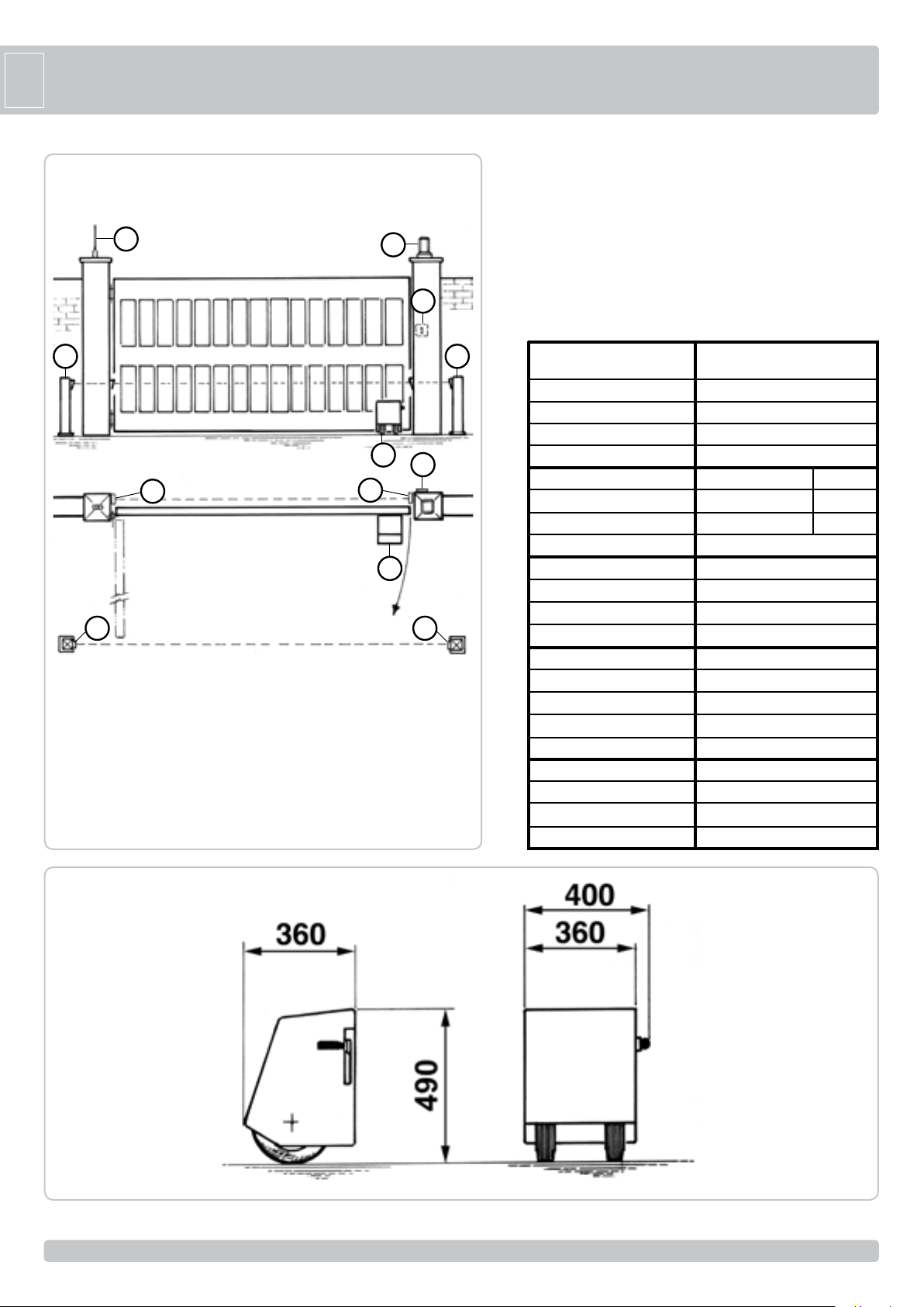
SYSTEM LAY-OUT
2
TECHNICAL FEATURES
Gearmotor for operating industrial swing gates with overall
maximum weight of 2000 kg.
The R50 is an irreversible electric gearmotor with adjustable
drive force, regulated by changing the pressure exerted by the
3
6
drive wheels on the ground.
The drive wheels are able to run over surface irregularities of
up to 6 cm (approx.), because the gearmotor unit slides along
a vertical track. The pressure setting between the drive wheels
and the ground can vary from 30 to 130 kg maximum and is
maintained by an adjustable spring.
4
5 5
1 - R50 operator
2 - Radio antenna
3 - Blinker
4 - Photoelectric cells (external)
5 - Photoelectric cells (internal)
6 - Key selector
55
1
6
4
1
1
TECHNICAL DATA
Max. leaf length
Max. leaf weight
Average opening time
Operating speed
EEC Power supply
Motor capacity
Power absorbed
Capacitor
EEC Power supply
Motor capacity
Power absorbed
Capacitor
230/50-60 Normative cycles
120/60 Normative cycles
Daily cycles suggested
Service
Consecutive cycles guaranteed
Grease
Actuator weight
Operating temperature
Protection grade
90°
R50
m 10
kg 2000
s. 78
m/s. 0,180 (50Hz) - 0,216 (60Hz)
230V~ 50Hz 60Hz
W 437 511
A 1,96 2,32
mF 16
120V~ 60Hz
W 251
A 2,26
mF 40
n° 3 - 78s/2s
n° 8 - 78s/2s
n° 300
60%
n° 4/78s
COMLUBE LHITGREASE EP/GR.2
kg 45
°C -10 ÷ +55°C
IP 54
Measurements in mm
24
24
2
Page 4
R50 INSTALLATION
G
B
RE-INSTALLATION CHECKS
P
The leaf must be fixed firmily on the hinges to the pillars, must not be
flexible during the movement and must move without frictions. The
ground on which the R50 wheels run must be solid and compact with
minimum gradient.
Gate features must be uniformed with the standards and laws in
force. The door/gate can be automated only if it is in a good condition
and its conditions comply with the EN 12604 norm.
- The door/gate leaf does not have to have a pedestrian opening. In
the opposite case it is necessary to take the appropriate steps, in
accordance with EN 12453 norm (for instance; by preventing the
operation of the motor when the pedestrian opening is opened, by
installing a safety microswitch connected with the control panel).
- No mechanical stop shall be on top of the gate, since mechanical
stops are not safe enough.
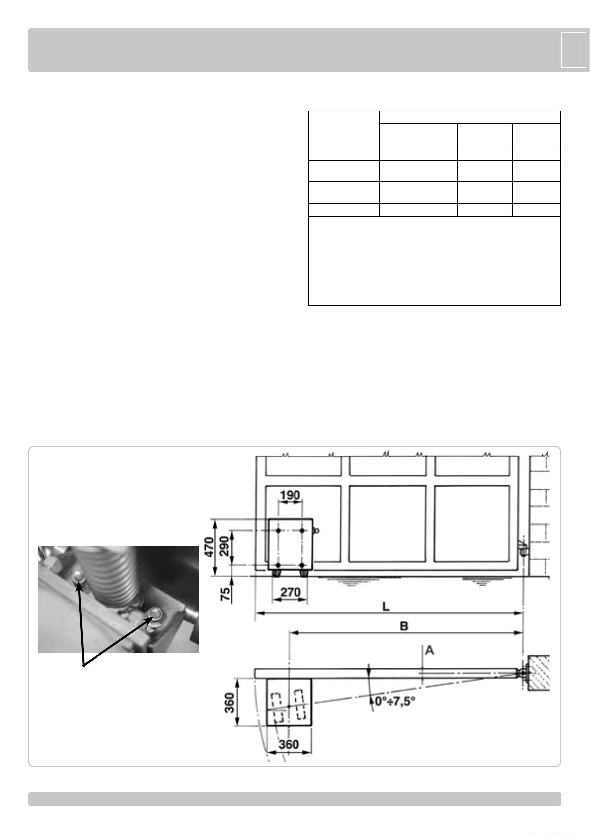
R50 INSTALLATION
The ground should be compact and without any excessive differences
in level along the tract destined for wheel run.
Position the gate about halfway, secure the gearmotor plate to the
corner of the gate leaf and ensure that the drive wheels rest on the
ground.
Drill four Ø 6.5 mm holes in the leaf, then tap them with M8 male
threading.
Insert four M8 bolts and tighten with a No. 13 wrench.
Remove the elastic pin which prevents the wheels from turning (Fig. 6).
If the drive wheels slide on the ground during operation, turn the set
screw on the spring clockwise to increase the pressure between the
Parts to install meeting the EN 12453 standard
COMMAND TYPE USE OF THE SHUTTER
Skilledpersons Skilledpersons
(outofpublicarea*) (publicarea)
withmannedoperation A B nonpossibile
withvisibleimpulses
(e.g.sensor)
withnotvisibleimpulses
(e.g.remotecontroldevice)
automatic CandD,orE CandD,orE CandD,orE
*atypicalexamplearethoseshutterswhichdonothaveaccesstoanypublicway
A:Commandbuttonwithmannedoperation(thatis,operatingaslongasactivated),
likecodeACG2013
B:Keyselectorwithmannedoperation,likecodeACG1010
C:Adjustablepowerofthemotor
D:Safetystripsand/orothersafety devicestokeepthrustforce withinthelimitsof
EN12453regulation-AppendixA.
E:Photocells,likecodeACG8026(Toapplyevery60÷70cmforalltheheightofthe
columnofthegateuptoamaximumof2,5m-EN12445point7.3.2.1)
wheels and the ground.
To reduce wheel wear during operation, loosen nuts (D) with a No. 13
wrench and tilt the rubber wheels so that the axles coincide with the
center of the gate leaf pivot point.
The wheels may be tilted by 0° to 7.5°. Retighten the two nuts.
The R50 is equipped with two waterproof, armored limit stops to
electrically control gate travel.
The limit stops should be positioned in accordance with installer
requirements.
CorE CorE CandD,orE
CorE CandD,orE CandD,orE
Unrestricteduse
D
25
25
B min [m] = (0,205+A) / 0,12
B [m] = 0,9 x L
Opening time [sec] = 7,85 x L
3
Page 5
G
B
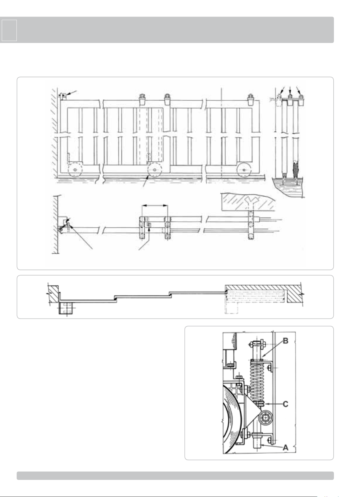
R50 APPLICATION ON MULTIPLE PANEL DOORS
In this case the R50 must be installed on the first leaf.
Limit switch
Wheels Ø120
Olive
Internal
Limit switch
Box
Mechanical stopper
External
250
EMERGENCY RELEASE
To be undertaken after disconnecting power supply.
In the event of a power failure, raise the side handle to lift the wheels
off the ground.
In order to carry out the manual operation of the gate leaf the followings
must be checked:
- That the gate is endowed with appropriate handles;
- That these appropriate handles are placed so to avoid safety risks for
the operator;
- That the physical effort necessary to move the gate leaf should not be
higher than 225 N, for doors/gates for private dwellings, and, 390N for
doors/gates for commercial and industrial sites ( values indicated in
5.3.5 of the EN 12453 norm
Box
Guide
4
5
A : Maximum stroke 60 mm during movement (holes or uneven ground)
B : Remove the elastic pin, after the unit is secured, to release the
spring.
C : Spring set screw.
26
26
6
Page 6
G
B
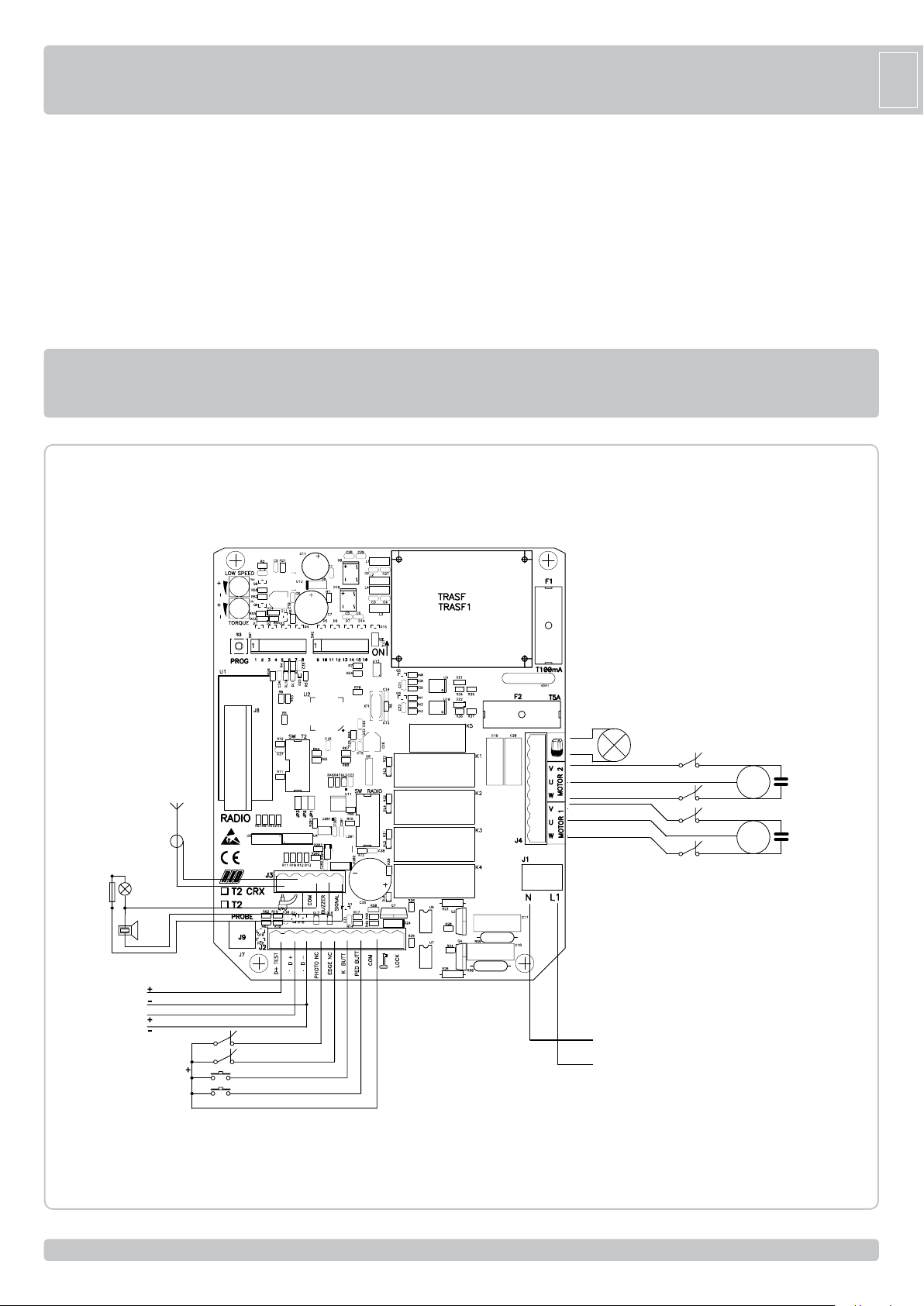
ELECTRICAL SAFETY DEVICES
The installation must be installed according to the current regulations
and laws.
Use the T2 electronic control unit.
For connections and technical data of accessories refer to the
appropriate booklets.
ELECTRIC CONNECTIONS
MAINTENANCE
To be undertaken by specialized staff after disconnecting power
supply.
Clean the wheel contact surfaces carefully once a week.
Check wheel/ground pressure and condition of motor wheels every six
months.
The motor should be overhauled every two years and the oil replaced.
T2 code BC07086
T2 CRX code BC07085
R=2,2KΩ
BUZZER
+
-
12Vdc for
AUTOTEST EDGE
12Vdc for
ACCESSORY
SUPPLY
AERIAL
SIGNAL
+
-
+
-
COAX
+
PHOTOCELL
EDGE
K BUTTON
PED. BUTTON
COM
BLINKER
POWER SUPPLY
LSC1 - limit switch close M1
LSO1 - limit switch open M1
LSC2 - limit switch close M2
LSO2 - limit switch open M2
LSO2
LSC2
LSO1
LSC1
MOTOR 2
MOTOR 1
CAPACITOR M2
CAPACITOR M1
27
27
Page 7
G
TR2
TR1
S3
J8
J5
J3
J7
J2
J4
J1
J6
JP1
JP2
JP3
JP17
ON
B
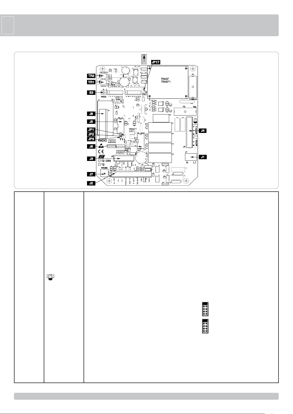
POINT A - CONTROL PANEL FEATURES
J1
J2
J3
J4
J5
J6
J7
J8
JP17
S3
TR1
TR2
N -L1
D+ TEST
D +
D PHOT. NC
EDGE NC
K BUTT.
PED. BUTT.
COM
LOCK
AERIAL
COM
BUZZER
SIGNAL
U - MOTOR 2
V-W - MOTOR 2
U - MOTOR 1
V-W - MOTOR 1
SW T2
SW RADIO
PROBE
RADIO
PROG
TORQUE
LOW SPEED
Main power supply 230 Vac 50/60 Hz (120V/60Hz upon request)
Safety strip self-test power supply +12Vdc
Accessories power supply +12Vdc
Accessories power supply -12Vdc
Photocells contact (NC)
Safety strip contact (NC)
Single pulse contact (NO)
Pedestrian opening contact (NO)
Common contact (common line for all the command and safety inputs)
Electric lock connection (MAX 15W 12V)
Radio Antenna
Common contact (common line for all the command and safety inputs)
Buzzer contact (12Vdc max 200 mA)
Gate open state output indicator (12Vdc 3W max)
Flashing light (max 40W )
MOTOR 2 COMMON CONNECTION
MOTOR 2 PHASE AND CAPACITOR CONNECTIONS
MOTOR 1 COMMON CONNECTION
MOTOR 1 PHASE AND CAPACITOR CONNECTIONS
DO NOT REMOVE ANY JUMPER!
OTHERWISE THE OPERATOR WILL NOT WORK!
(only CRX control board)
DO NOT REMOVE ANY JUMPER!
OTHERWISE THE OPERATOR WILL NOT WORK!
Not available for R50
Built-in radio module (model CRX), or connector for radio receiver RIB, 12 Vdc supply
To select 1 motor (M1) or 2 motors (M1 and M2)
Programming button
Electronic torque regulator
Electronic regulator for low speed on approach motor
28
28
Page 8

G
B
POINT B - SETTINGS
DIP 1 (ON) MOTOR ROTATION DIRECTION CHECK (See Point
DIP 2 (ON) PROGRAMMING (See Point D)
DIP 1-2 STORAGE/DELETION OF RADIO CODES FOR COMPLETE
DIP 1-3 STORAGE/DELETION OF RADIO CODES FOR PEDESTRIAN OPENING
DIP 2-1 PROGRAMMING OF THE PEDESTRIAN OPENING (See Point F)
DIP 3 ON - Automatic Closing ENABLED
OFF - Automatic Closing DISABLED
DIP 4 ON - Photocells active only in closing
OFF - Photocells always active
DIP 5 ON - blinker pre-flashing
OFF - blinker normal-flashing
DIP 6 OFF - STEP BY STEP
Single pulse contact (K BUTT)
Pedestrian button (PED BUTT)
Radio Receiver command
ON - AUTOMATIC
Single pulse contact (K BUTT)
Pedestrian button (PED BUTT)
Radio Receiver command
DIP 7 ON - low speed in approaching ENABLED
OFF - low speed in approaching DISABLED
DIP 8 ON - electric lock command ENABLED
OFF - electric lock command DISABLED
DIP 9 ON - Hammering on complete close position to ease Manual Release
- Hammering before opening to ease electric lock unlocking
OFF - no impulse
DIP 10 ON - Extra thrust when reached closing position to make sure that the
OFF - no impulse
DIP 11 ON - black out function ENABLED (See chart 1)
OFF - black out function DISABLED
DIP 12 ON - close command after the transit through the photocell ENABLED
OFF - close command after the transit through the photocell DISABLED
DIP 13 ON - safety strip self-test ENABLED
OFF - safety strip self-test DISABLED
DIP 14 OFF OBLIGATORY FOR R50 MOTOR
DIP 15 ON OBLIGATORY FOR R50 MOTOR
DIP 16 ON OBLIGATORY FOR R50 MOTOR
JP 17 OPEN JUMPER 1 motor (M1) - 1 leaf
CLOSE JUMPER 2 motors (M1 and M2) - 2 leaves
JP1 => Pay attention that the jumper is inserted!
JP2 => Pay attention that the jumper is inserted!
JP3 => Pay attention that the jumper is inserted!
TORQUE TR1 Electronic regulator for motor torque
Adjustment of motor torque is carried out using the TORQUE Trimmer which varies
the output voltage to the head/s of the motor/s (turn clockwise to increase torque).
This torque control is activated after 2 seconds form any manoeuvre begging, whereas
the motor is turned on at full power to guarantee the starting at the manoeuvre begging.
PAY ATTENTION: IF THE TORQUE TRIMMER SETTING IS CHANGED, IT IS
PREFERABLE TO REPEAT THE TIME PROGRAMMING.
LOW SPEED TR2 Electronic regulator for low speed on approach
Adjustment of low speed is carried out using the LOW SPEED Trimmer which varies
the output voltage to the head/s of the motor/s (turn clockwise to increase speed).
Adjustment is carried out to establish the correct speed at the completion of opening
and closing, depending on the structure of the gate, or if there is any light friction
that could compromise the correct working of the system. The low speed is activated
(DIP7 OFF) when the gate leaf is 0.50-0.60 meters away from the complete close or
open position.
ATTENTION: WHEN USING HYDRAULIC OPERATORS
When using the hydraulic operators the deceleration phase may not operate
correctly; in that case it is advisable to disable the feature of the deceleration by
putting DIP 7 in the OFF mode.
LED WARNING
DL1 - programming activated (red)
DL2 - radio code programming (green) (only for CRX)
DL3 - gate opening M2 (green)
C)
OPENING (DIP 1 ON followed by DIP 2 ON) (POINT G)
ONLY FOR CRX MODELS
(DIP 1 ON followed by DIP 3 ON) (POINT H) ONLY FOR CRX MODELS
mechanical bolt is fixed into the ground
DL4 - gate closing M2 (red)
DL5 - gate opening M1 (green)
DL6 - gate closing M1 (red)
DL7 - photocell contact (NC) (red)
DL8 - safety strip contact (NC) (red)
FUSES
F1 T100mA Accessories protection fuse
F2 5A Motor protection fuse
POINT C - MOTOR ROTATION DIRECTION CHECK
1 - Unlock the operators with the Manual Release - swing open the leaves about
halfway and lock again the operators.
2 - Turn DIP1 to ON position. The red LED DL1 starts blinking.
3 - Press the PROG button and hold it - When GREEN LEDS DL3 and DL5 are
on, the gate leaves are opening (with a phase shift of 2 seconds). Check the
leaves swinging and the opening mechanical stopper position (movement is now
performed in “man present” mode, open-close-open-etc.).
If any of the leaf closes instead of opening, release PROG button, turn off the main
power and reverse the two phase wires (V1/2 and W1/2) of the relevant motor/s.
4 - Press the PROG button and hold it to CLOSE completely the gate. When RED
LEDS DL4 and DL6 are on, the gate leaves are closing (with a phase shift of 4
seconds). Check leaves swinging and the closing mechanical stopper position.
5 - After 3 seconds motor starting and for the next 10 seconds motor working, the
torque controls automatically activated. Set the motor torque by the TORQUE
Trimmer/s which varies the output voltage to the motor/s (turn clockwise to increase
the torque).
6 - After other 10 seconds motor working, the low speed controls automatically
activated (DIP7 ON). Set the motor low speed by the LOW SPEED Trimmer to
select the gate leaf low speed in approaching.
7 - Close completely the gate.
8 - Turn DIP1 to OFF position, LED DL1 turns off.
During Point C procedure, safety devices (photocells and safetystrip) are not
active and the remote control cannot operate.
(#) In Point D, Point E and Point F procedures, all the safety devices (photocells and
safety strip) will be active, so they must be properly installed and connected to the
control board. Any changing of the safety devices input state, will stop the Point D,
Point E or Point F procedure that must be repeated from the beginning.
POINT D - PROGRAMMING FOR 2 MOTORS (#)
1 - The gate must be fully closed.
2 - Turn DIP2 to ON position, LED DL1 starts blinking
3 - Press PROG. Button, motor M1 opens.
4 - Once reached the open position, let 1 second pass and press the PROG button to
cut out motor M1 (time travel of M1 has now been just stored with this operation).
5 - Motor M2 opens, automatically.
6 - Once reached the open position, let 1 second pass and press the PROG button to
cut out motor M2 (time travel of M2 has now been just stored with this operation).
The gap of time between now (stop of motor M2) and the next pressing of the
PROG. button (see step 7 below) will be then stored as waiting time for Automatic
Closing feature.
7 - Press PROG. button, M2 closes and the Automatic Closing time is stored (see
DIP3 function to enable or disable the Automatic Closing feature). The gap of time
between now (close of motor M2) and the next pressing of the PROG. button (see
step 8 below) will be stored as time delay between motor M2 and motor M1 closing,
during normal operations.
8 - Press the PROG. button, motor M1 closes thus setting the delay time between M2
and M1, as explained in step 7 above.
9 - The LED DL1 will turn OFF, signalling exit from the Point D procedure.
Closing of the gate will be carried out at normal speed and only on approaching
total closing at low speed (depending on the adjustment of LOW SPEED trimmer).
10 - Turn DIP2 to OFF position.
During Point D procedure, the safety devices (photocells and safety strip) are active.
POINT E - PROGRAMMING FOR 1 MOTOR (M1) (#)
ATTENTION: in order to manage one motor only, OPEN JUMPER JP17.
1 - The gate must be fully closed.
2 - Turn DIP2 to ON position, the LED DL1 starts blinking
3 - Press PROG. button, the motor M1 opens.
4 - Once reached the open position, let 1 second pass and press the PROG button to
cut out motor M1 (time travel of M1 has now been just stored with this operation).
The gap of time between now (stop of motor M1) and the next pressing of the
PROG. button (see step 5 below) will be then stored as waiting time for Automatic
Closing feature.
5 - Press PROG. button, M1 closes and the Automatic Closing time is stored (see
29
29
Page 9
G
B
DIP3 function to enable or disable the Automatic Closing feature).
6 - The LED DL1 will turn OFF, indicating exit from the Point E procedure. Closing of
the gate will be carried out at normal speed and only on approaching total closing at
low speed (depending on the adjustment of LOW SPEED trimmer).
7 - Turn DIP2 to OFF position.
During Point E procedure, the safety devices (photocells and safety strip) are active.
POINT F - PROGRAMMING OF PEDESTRIAN OPENING (#)
1 - The gate must be fully closed.
2 - Turn DIP2 to ON position, the LED DL1 starts blinking quickly.
3 - Immediately, turn also DIP1 to ON position, the LED DL1 starts blinking slowly.
4 - Press the pedestrian pushbutton PED. BUTT, motor M1 opens
5 - When the motor M1 leaf is opened enough for the pedestrian crossing, press the
pedestrian pushbutton to stop the travel (thus defining the opening stroke of motor
M1). The gap of time between now (stop of motor M1) and the next pressing of
the PROG. button (see point 6 below) will be stored as waiting time for Pedestrian
Automatic Closing feature.
6 - Press the pedestrian pushbutton PED. BUTT, M1 closes and the Pedestrian
Automatic Closing time is stored (see DIP3 function to enable or disable the
Automatic Closing feature).
7 - Turn DIP1 to OFF position.
8 - Turn DIP2 to OFF position.
During Point F procedure, the safety devices (photocells and safety strip) are active.
POINT G - PROGRAMMING RADIO CODES FOR COMPLETE OPENING
(UP TO 62 CODES - ONLY FOR CRX MODELS)
You can only programme the codes if the gate is closed.
1 - Position DIP 1 to ON and then DIP 2 to ON.
2 - The red programming DL1 LED will flash ON and OFF, one second on each, for
10 seconds.
3 - Press the remote control button (normally channel A) within the 10 seconds
proscribed. If the remote control has been correctly programmed, the DL2 LED
(green) will flash once.
4 - The code programming time resets automatically so that you can programme the
next remote control.
5 - To finish programming, let 10 seconds pass and then press the PROG. button
briefly. The red DL1 LED will stop flashing.
6 - Reposition DIP 1 to OFF and DIP 2 to OFF.
7 - You have completed the procedure
PROCEDURE FOR DELETING ALL RADIO CODES USED ONLY FOR COMPLETE
OPENING
You can only delete the codes if the gate is closed.
1 - Position DIP 1 to ON and then DIP 2 to ON.
2 - The red programming DL1 LED will flash ON and OFF, one second on each, for
10 seconds.
3 - Press and hold the PROG button for 5 seconds. The green DL2 LED will flash twice
to confirm that the stored codes have been deleted.
4 - The red programming DL1 LED remains active and you can programme new codes
as shown above if required.
5 - Reposition DIP 1 to OFF and DIP 2 to OFF.
6 - You have completed the procedure.
HOW TO CHECK IF THE MEMORY IS FULL FOR RADIO CODES USED ONLY FOR
COMPLETE OPENING
You can only check the memory if the gate is closed.
1 - Position DIP 1 to ON and then DIP 2 to ON.
2 - The green DL2 LED will flash 6 times if the memory is full (64 codes have been
stored).
3 - After this, the DL1 programming LED will remain active for 10 seconds, so that you
can delete all codes if required.
4 - Reposition DIP 1 to OFF and DIP 2 to OFF.
5 - You have completed the procedure
POINT H - PROGRAMMING RADIO CODES FOR PEDESTRIAN
OPENING
(UP TO 62 CODES - ONLY FOR CRX MODELS)
You can only programme the codes if the gate is closed.
1 - Position DIP 1 to ON and then DIP 3 to ON.
2 - The red programming DL1 LED will flash ON and OFF, one second on each, for
10 seconds.
3 - Press the remote control button (normally channel B) within the 10 seconds
proscribed. If the remote control has been correctly programmed, the DL2 LED
(green) will flash once.
4 - The code programming time resets automatically so that you can programme the
next remote control.
5 - To finish programming, let 10 seconds pass and then press the PROG. button
briefly. The red DL1 LED will stop flashing.
6 - Reposition DIP 1 to OFF and DIP 3 to OFF.
N.B: IF THE DL1 LED CONTINUES TO FLASH RAPIDLY, THIS MEANS THAT
DIP 1 IS STILL POSITIONED TO ON AND ANY MANOEUVRE HAS BEEN
DELETED.
7 - You have completed the procedure.
PROCEDURE FOR DELETING ALL RADIO CODES USED ONLY FOR COMPLETE
OPENING
You can only delete the codes if the gate is closed.
1 - Position DIP 1 to ON and then DIP 3 to ON.
2 - The red programming DL1 LED will flash ON and OFF, one second on each, for
10 seconds.
3 - Press and hold the PROG button for 5 seconds. The green DL2 LED will flash twice
to confirm that the stored codes have been deleted.
4 - The red programming DL1 LED remains active and you can programme new codes
as shown above if required.
5 - Reposition DIP 1 to OFF and DIP 3 to OFF.
6 - You have completed the procedure.
HOW TO CHECK IF THE MEMORY IS FULL FOR RADIO CODES USED ONLY FOR
COMPLETE OPENING
You can only check the memory if the gate is closed.
1 - Position DIP 1 to ON and then DIP 3 to ON.
2 - The green DL2 LED will flash 6 times if the memory is full (64 codes have been
stored).
3 - After this, the DL1 programming LED will remain active for 10 seconds, so that you
can delete all codes if required.
4 - Reposition DIP 1 to OFF and DIP 3 to OFF.
5 - You have completed the procedure.
FUNCTIONING OF CONTROL ACCESSORIES
ATTENTION: ONLY IMPULSIVE COMMANDS HAVE TO BE CONNECTED.
Make sure that any other type of command accessories (e.g. mass detectors)
used on the installation are set in the IMPULSIVE mode, otherwise, the gate
will be operated even without the protection of the safety devices.
STEP BY STEP or AUTOMATIC commands
(K BUTT button, PED BUTT button, RADIO REMOTE button)
DIP 6 - OFF The K BUTT, the PED BUTT button, the RADIO REMOTE buttons
perform the cyclic command open-stop-close-open-stop-etc.
DIP 6 - ON The K BUTT, the PED BUTT button, the RADIO REMOTE buttons
perform:
- the open command, if pressed with the gate completely closed
- the close command, if pressed with the gate completely opened
- no effect, if pressed during the gate opening
- the gate re-open, if pressed while the gate is closing
The K BUTT opens the gate completely, whereas the PED BUTT opens the gate
partially as described in Point F.
CLOCK FUNCTION
If you want the Clock Function must request T2 with firmware 08.
ATTENTION: A CLOCK CONNECTED TO T2 with fw 09 or more ACTIVATES
THE AUTOMATIC MOVEMENT OF THE GATE WITHOUT HAVING THE
PROTECTION OF THE SAFETY DEVICES!
The Clock Function is useful during rush hours, when traffic is heavy and the flow is
slow (e.g. entrance/exit of employees, emergencies in residential areas or car parks
and, temporarily, for removal vans) and it’s necessary to keep the gate opened.
CLOCK FUNCTION APPLICATION
It is necessary to request a T2 control panel with firmware 08.
Select the automatic functioning DIP 6 OFF.
It can be done by connecting a switch and/or a daily/weekly clock either in parallel to
the K BUTT button or instead of the K BUTT button. When the control board receives
this command, the gate will open and by keeping this contact closed for all the time of
the gate opening, the Clock Function is automatically activated. In fact, once reached
the open position, the gate will remain opened and all of the control board functions
are blocked. Only when K BUTT contact is released, the control board functions are
re-activated and the Automatic Closing restarts (if enabled) doing the countdown to
the gate closing.
PEDESTRIAN command (PED BUTT - COM)
This command is useful to open the gate partially, just enough, for example, to permit
30
30
Page 10
G
B
a pedestrian crossing. In fact, the Pedestrian command (see Point F) is carried out
only by opening the motor M1 just enough for a pedestrian to pass, as described into
the Point F procedure.
From the Pedestrian opening position the Automatic Closing can be enabled or
disabled with DIP3.
From the Pedestrian opening position, the gate can be completely opened by the
OPEN or by the K BUTT button or by the RADIO button.
AUTOMATIC CLOSING (from the COMPLETE open position)
The Automatic Closing from the complete open position can be enabled turning ON
the DIP3.
The maximum gap of time that can be programmed is 5 minutes (see Point D and E).
AUTOMATIC CLOSING (from the PEDESTRIAN open position)
The Automatic Closing from the pedestrian open position can be enabled turning ON the
DIP3. The maximum gap of time that can be programmed is 5 minutes (see Point F).
ELECTRIC LOCK (LOCK A+) command
The DIP 8 in the ON position enables the Electric Lock (MAX 15W 12V) command. The
Electric Lock (LOCK A+) will be automatically turned ON each time the gate opens. If
the DIP8 is OFF, the Electric Lock command is DISABLED.
The Electric Lock remains active for 1,5 seconds.
MANUAL RELEASE FACILITY
The DIP 9 in the ON position enables the Manual Release Facility. Once the gate has
completely closed, a short reversal manoeuvre (0.2 seconds) will be done to ease
manual release.
ELECTRIC LOCK unlocking FACILITY
The DIP 9 in the ON position enables the Electric Lock unlocking Facility. From close
position, just before opening, the gate will perform a short closing manoeuvre (0.5
seconds) to ease unlocking from electric lock.
ELECTRIC LOCK coupling FACILITY
The DIP 10 in the ON position enables the Electric Lock coupling Facility. Once the gate
has closed, a short hammering close pulse (0.5 seconds) will be done at full power to
guarantee the electric lock or mechanical bolt coupling.
FUNCTIONING OF SAFETY ACCESSORIES
PHOTOCELL (PHOT - COM)
In case the switch DIP4 is in the OFF position, the photocells are active both in gate
opening and in gate closing. In this configuration, if an obstacle cuts the photocell
beam:
- while the gate is closing, the gate will open
- while the gate is opening, the gate will stop and will restart opening when the obstacle
is removed
- while the gate is still, it will not move neither in opening nor in closing.
In case of the switch DIP4 is in the ON position, the photocells are active only in gate
closing.
In this configuration, if an obstacle cuts the photocell beam:
- while the gate is closing, the gate will open
- while the gate is opening, the gate will continue open
- while the gate is still, it will open if a open command is request, it will remain still if a
close command is request.
The photocell input (PHOT - COM) is a NORMALLY CLOSED contact.
In case there are more couple of photocells, the contacts from all the photocell
receivers must be connected in series.
In case the photocells are not installed, this contact must be short circuited with a wire
jump (from PHOT to COM) to permit the gate to operate.
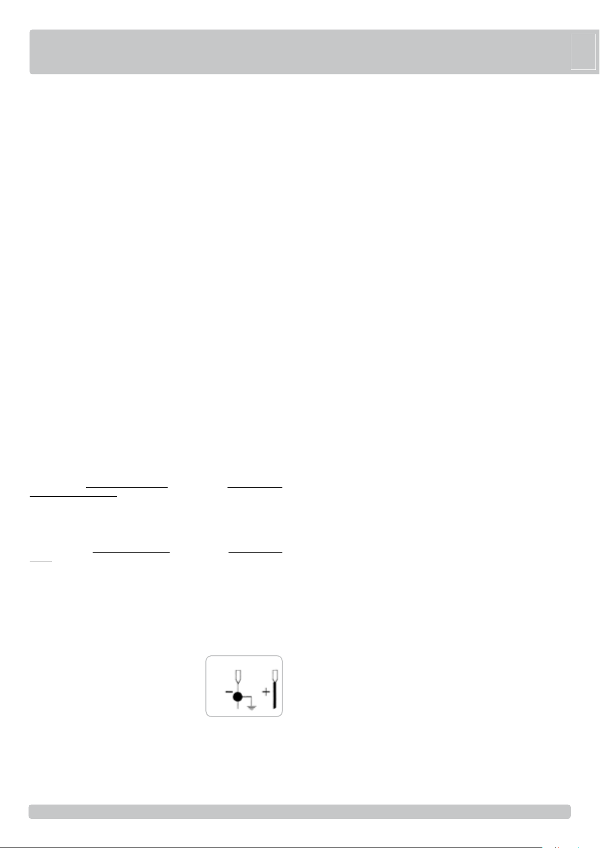
ATTENTION: In case the receiver led remains lit,
malfunctioning of the main supply is suspected.
It is advisable to connect electrically to earth the
columns or the photocells stands to the terminal D-, to
shield the photocells from external noise.
Be careful not to short circuit the system when the
supply phases are inverted!
AUTOMATIC CLOSING AFTER THE TRANSIT THROUGH THE PHOTOCELL
This option could be useful to close automatically the gate when the vehicle left and
disengaged the photocell beam. If the DIP12 is turned ON, this function is activated and
the PHOTO input will have two purposes:
- detect the obstacle and prevent the gate movement in according with the DIP4
position;
Term.
D-
12Vdc
- close the gate as soon as the vehicle leaves the photocell beam.
If DIP12 ON and DIP4 OFF
If the gate is opening and a vehicle crosses the photo beam, the gate will stop. When
the vehicle leaves, the gate will close automatically after 1 second pause.
If DIP12 ON and DIP4 ON
If the gate is opening and a vehicle crosses the photo beam, the gate will continue to
open. When the vehicle leaves, the gate will stop and then closes automatically after
1 second pause.
If the complete gate open position is reached before the vehicle leaving, the
DIP12 will be ignored and the automatic closing will be managed in according
to the DIP3 position.
PAY ATTENTION: it is highly recommended to check photocells operation at least
every 6 months.
SAFETY STRIP (EDGE - COM)
If an obstacle presses the safety strip:
- while the gate is still, it will not move neither in opening nor in closing
- while the gate is closing, the gate will open
- while the gate is opening, the gate will close.
In case the safety strip is held pressed a further quick reversion, after 2 seconds, is
performed. The gate interrupts any movement and this alarm state is indicated by 1
minute Blinker flashing. The normal gate operations can be restored by pressing any
push button or radio commands.
The safety strip input (EDGE - COM) is a NORMALLY CLOSED contact.
In case there are more than one safety strip, all their contacts must be connected in
series.
In case the safety strip is not installed, this contact must be short circuited with a
wire jump (from EDGE to COM) to permit the gate to operate and the Safety Strip
test must be disabled (DIP 13 OFF).
FUNCTIONING IN DEAD MAN MODE WHEN THE SAFETY DEVICES ARE FAILING
If the safety edge fails or remains engaged for more than 5 seconds, or if photocell
fails or remain engaded for more than 60 seconds, the K BUTTON and PEDESTRIAN
commands will work only in dead man mode.
The signal that this mode has been activated is given by the blinking of the
programming led.
With the blinking of the programming led, the opening and closing operation are
allowed only with the command button pressed and held. The radio commands and
that of automatic closing, will be excluded, since their use in this mode, is not allowed
by the norms.
Once the failing safety device is repaired, in automatic after 1 second, all standard
commands that were selected, such as step by step, automatic mode, radio commands
and automatic closing start functioning again.
Note 1: during this functioning in dead man mode, in case of damage to the safety
strips (or photocells) the photocells (or safety strips) still work by interrupting
the operation in progress.
During the dead-man operation, press and hold the K BUTTON or the PED BUTTON
for the complete operation, and until the switching off of the leds of the motors (DL3
- DL5 total opening M2 - M1 - pedestrian DL5 - DL4 - DL6 total closing M2 - M1 pedestrian DL6), or of the blinker, when installed.
The dead-man operation is only an emergency operation which must be activated
for a very short period and with the complete installation at sight so to have a
secure and safe control of the system. As soon as possible however, the failing
safety devices must be repaired and activated.
TESTING THE SAFETY STRIP equipment
The switch DIP13 ON enables to test the safety strip equipment. The test is performed
every time the gate completes a full opening. The test is available only if the safety
strip device is equipped with a dedicated power supply input.
In fact, the safety strip equipment power supply input can be connected to the D+TEST
and D- outputs (DIP13 ON). Automatically, every time the gate completes a full
opening, just before closing, the control board switches OFF the D+TEST and D- power
supply output for a very short time. While the safety strip power supply is switched OFF,
if everything is working fine the safety strip contact (EDGE - COM) must open. In case
the test fails, no other gate manoeuvre will be allowed.
NOT ALL THE SAFETY STRIPS CAN BE TESTED, THUS THE SWITCH DIP13
MUST BE LEFT OPEN.
BLINKER
Connect the flashing light to the blinker output, use flashing lights ACG7059 and bulbs
of 40W maximum.
PRE-FLASHING function
The DIP 5 in the ON position enables the pre-flashing, the BLINKER starts flashing 3
seconds before every movement of the gate.
31
31
Page 11
G
B
The DIP 5 in the OFF position disables any pre-flashing, the BLINKER starts flashing
and the motors will start at the same time.
BUZZER
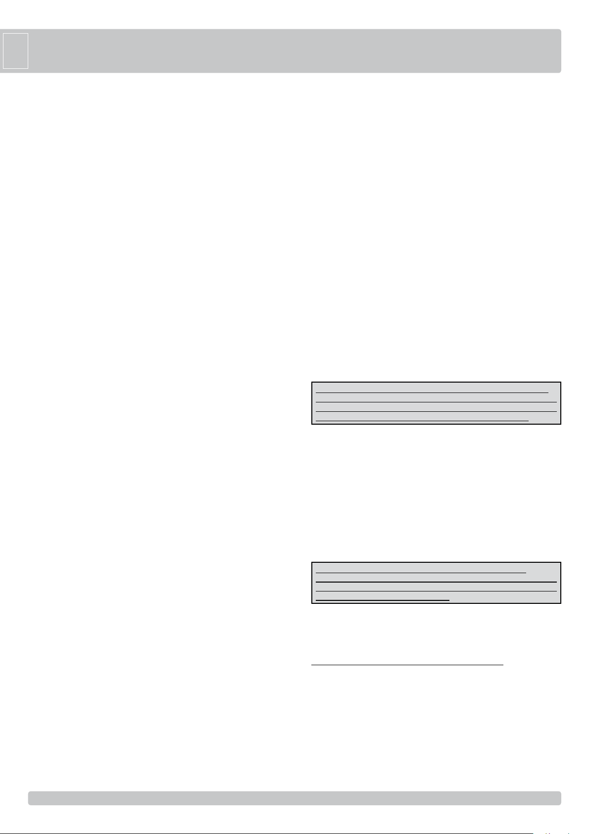
The current supplied to the Buzzer will be 200 mA at 12Vdc.
During the normal operation of the gate, opening and closing, the buzzer will buzz
intermittently. Only during the alarm situations (safety strip) the buzzing will almost be
constant.
GATE OPEN INDICATOR (SIGNAL - COM)
Should you need to have an indication about the leaf position, the output SIGNAL COM can be connected to a 12Vdc bulb of 3W maximum. It is turned ON when the
gate is open or partially open, it is turned OFF only when the gate is completely closed.
WE RECOMMEND NOT TO OVERLOAD THE INDICATOR OUTPUT (SIGNAL COM) OTHERWISE THE GATE FUNCTIONING COULD BE COMPROMISED OR
THE CONTROL BOARD COULD BE DAMAGED
RESTORATION OF OPERATIONS AFTER A BLACKOUT
If DIP 11 is turned OFF the blackout function is DISABLED.
If DIP 11 is turned ON the blackout function is ENABLED.
In case of a blackout occurs and the blackout function is enabled (DIP11 ON), when
the main power returns, automatically the operator will function according to the chart 1.
chArT 1
During blackout At the return of the network
power supply.
Ifthegateistotallyclosed Itwillremainclosed
Ifthegateisattheopeningstage Itwillcontinueopening
Ifthegateistotallyopen(withdip3OFF) Itremainsopen.Consequently
closingoperationsofthegate
canbecontrolled.
Ifthegateistotallyopen(withdip3ON) Itremainsopen,butatthe
expireryoftheautomatic
closuretimeclosureoperation
startsoff.
Ifthegateisintheclosurestage Itcontinuesclosing.
Ifthegateisinthesafetyedgealarm Thesafetyedgealarmstarts
offagain.
TECHNICAL SPECIFICATIONS
- Humidity < 95% without
condensation
- Power supply voltage 230 o 120V~ ±10%
- Frequency 50/60 Hz
- Maximum absorption 32 mA
- Interruptions in electricity supply 100ms
- Maximum power of gate open indicator 12Vdc 3W (equivalent to
1 bulb of 3W or 5 LED
with serial resistance of
2,2 kΩ)
- Maximum load of blinker output 40W with resistive charge
- Current available for photocells and accessories 500mA 12Vdc
- Current available on radio connector 200mA 12Vdc
TECHNICAL RADIO SPECIFICATIONS (Only CRX models)
- Reception frequency 433,92MHz
- Impedance 52 Ω
- Sensitivity >2.24µV
- Excitation time 300ms
- De-excitation time 300ms
- Codes in store N° 62
- All the inputs must be used as clean contacts because the power supply is generated
internally (safe voltage) in the card and it is set in a way to guarantee the use of the
double insulation and reinforced in relation to parts with hazardous voltage.
- Any external circuits connected to the outputs of the control board, must be carried
out to make sure the double or reinforced insulation is used in relation to parts with
hazardous voltage.
- All the inputs are run by a programmed integrated circuit which carries out a self-
check at the beginning of each operation.
TROUBLE SHOOTING
After having carried out all connections, by carefully following the layout and having positioned the gate in intermediate position, check the correct ignition of
LEDS DL7, DL8.
In case of no ignition of the LEDS, always with gate in intermediate position, check the following and replace any faulty components.
DL7 switched off Faulty photocells
DL8 switched off Faulty safety edge (In case the edge is not connected, carry out jumper between COM and EDGE)
During functioning with personnel present, with DIP 1 at ON, check that during opening of M1 and M2 the green DL5 and DL3 LEDS switch on and that during
closing of M1 and M2 the red DL6 and DL4 LEDS switch on.
If not, invert clamps V and W on the motor terminal board of the interested motor.
FAULT
After having carried out the various connections and having supplied voltage, all the LEDS
are switched off.
The motor opens and closes, but it has no strength and moves slowly.
The gate opens but does not close after the time set.
The gate does not open or close by activating the various K and RADIO buttons.
By activating the K button the gate does not move.
The electric lock does not work.
Check the integrity of fuses F1 and F2. In case of interrupted fuse use only of
adequate value F2 = 5A F1 = 100mA.
Check trimmers TORQUE and LOW-SPEED adjustment.
Ensure to have set DIP 3 at ON. Button K BUTTON always inserted in automatic
functioning mode (DIP 6 OFF). Replace button or switch of the selector switch.
Failed edge self-test => check the connections between electronic board and edge
feeder.
Attention: if not using a feeder for edges, DIP 10 must be at OFF position.
Faulty safety edge contact. Faulty photocells contact with DIP 4 OFF.
Fix or replace the relative contact.
Impulse K always inserted. Check and replace any buttons or micro-switches of the
selector switch.
Ensure to have enabled DIP 8 at ON.
SOLUTION
32
32
Page 12
ACCESSORIES -
For the connections and the technical data of the optional equipments follow the relevant
handbooks.
G
B
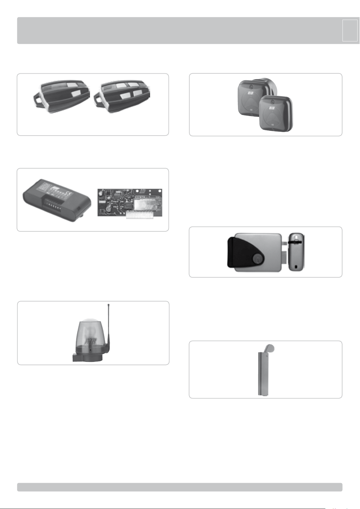
RADIO TRANSMITTER SUN
SUN 2CH code ACG6052 SUN 4CH code ACG6054
SUN CLONE 2CH code ACG6056 SUN CLONE 4CH code ACG6058
CODE LEARNIG SYSTEM RADIORECEIVERS
RX91/A quarzata and coupling code ACG5005
RX91/A quarzata and terminal board code ACG5004
RX433/A super eterodyne and coupling code ACG5055
RX433/A super eterodyne and terminal board code ACG5056
RX433/A 2CH super eterodyne, 2 channel and coupling code ACG5051
RX433/A 2CH super eterodyne, 2 channel and terminal board
code ACG5052
FIT SYNCRO
FIT SYNCRO PHOTOCELLS for the wall-installation code ACG8026
The range you can set is 10-20 m, 30÷60ft.
You can fit many couples close together thanks to the synchronising
circuit.
Add the SYNCRO TRANSMITTER code ACG8028
for more than 2 photocells couples (up to 4).
COUPLE OF BUILT-IN BOXES FOR THE FIT SYNCRO
code ACG8051
ELECTRIC LOCK
SPARK
In order to make the systems mentioned above give the best
performances, you need to install an antenna tuned on the frequency
of the radio receiver installed.
N.B. Pay attention to not let the central wire of the cable to came
Into contact with the external copper sheath, since this would
prevent the antenna from working.
Install the antenna vertically and in such a way the remote control can
reach it.
SPARK BLINKER WITH IN-BUILT INTERMITTENT CARD
code ACG7059
LATERAL SUPPORT code ACG7042
SPARK ANTENNA 91 code ACG5454
SPARK ANTENNA 433 code ACG5452
Horizontal lock - right external view - 12Vac code ACG8660
Horizontal lock - left external view - 12Vac code ACG8670
Vertical lock - 12Vac code ACG8650
MECHANICAL BOLT
Mechanical bolt suitable for 2 leaves gate to latch closed the gate to the
ground. code ACG5000
33
33
Page 13
R50
Questo prodotto è stato completamente progettato e costruito in Italia · Ce produit a été complètement développé et fabriqué en Italie · This product has been completely
developed and built in Italy · Dieses Produkt wurde komplett in Italien entwickelt und hergestellt
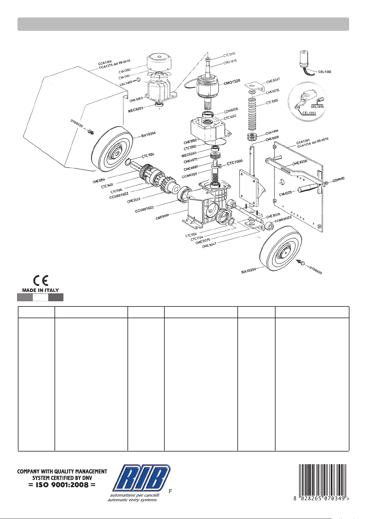
Codice Denominazione Particolare Codice Denominazione Particolare
BA10204 Ruota trascinamento R50
CCA1301
CCA1214 dal 09-2010 Piastra di base
CCA1302
CCA1375 dal 09-2010 Carter
CCU6010ZZ Cuscinetto schermato
MEC6203 Cuscinetto schermato
CCM6205 Cuscinetto schermato
CEL1076 Pressacavo PG13.5
CEL1463 Blocca Cavo SR6P3-4
CEL1355 Finecorsa 3SE3120-1G
CEL1382 Condensatore 16µF 450V
CME1054 Albero di traino
CME2022 Corona con mozzi Z=38
CME4072 Ingranaggio Z=29
CME5075 Bussola inf. R50
CME5076 Bussola sup. R50
CME8035 Supporto motore R50
CME8038 Timone regolab. R50
CME8047 Squadretta di guida R50
CME8200 Leva di sblocco manuale R50
CME8997 Vite senza fine
CME9150 Controflangia
CME9353 Cappellotto
CME9400 Carcassina
CMO1245 Rotore con albero
CMO1320 Statore 230V 50/60Hz 1P
CCM6302ZZ Cuscinetto 6302ZZ
CTC1006 Chiavetta 6x6x20
CTC1069 Molla per R50
CTC1104 Paraolio 50x72x10
CTC1124 Seeger E28
CTC1136 Seeger I 80
CTC1206 Molla a tazza
CTC1350 Anello di tenuta
25014 CASTENEDOLO (BS) - ITALY
Via Matteotti, 162
Tel. +39.030.2135811
Fax +39.030.21358279
www.ribind.it - [email protected]
Codice Denominazione Particolare
CTC1401 Paraolio 50x80x8
CTC1402 Paraolio30x47x7
CVA1029 Manopola MCG 28 85 GIR
CVA1380 Copriventola motore
CVA1381 Ventola
CVA1406 Ghiera reg. friz. Prem.
CZM6006 Cuscinetto motore 6006ZZ
DDMM10 Dado 10MA medio
DTE8X25 Vite TE 8X25 UNI5739
Cod. CVA1246 - 12092012 - Rev. 28
 Loading...