

RHINO NVR6ENT, NVR4ENTPACK User Manual

NVR6ENT / NVR4ENTPACK
User Manual

IMPORTANT SAFEGUARD
All lead-free products offered by the company comply with the requirements of the
European law on the Restriction of Hazardous Substances (RoHS) directive, which means
our manufacture processes and products are strictly “lead-free” and without the hazardous
substances cited in the directive.
The crossed-out wheeled bin mark symbolizes that within the European Union the product
must be collected separately at the product end-of-life. This applies to your product and
any peripherals marked with this symbol. Do not dispose of these products as unsorted
municipal waste. Contact your local dealer for procedures for recycling this equipment.
This is a class A product. In a domestic environment this product may cause radio
interference in which case the user may be required to take adequate measures.
Federal Communications Commission Interference Statement
This equipment has been tested and found to comply with the limits for a Class A digital device, pursuant to
Part 15 of the FCC Rules. These limits are designed to provide reasonable protection against harmful
interference when the equipment is operated in a commercial environment. This equipment generates, uses,
and can radiate radio frequency energy and, if not installed and used in accordance with the instruction
manual, may cause harmful interference to radio communications. Operation of this equipment in a residential
area is likely to cause harmful interference in which case the user will be required to correct the interference at
his own expense.
This device complies with Part 15 of the FCC Rules. Operation is subject to the following two conditions:
(1) This device mat not cause harmful interference, and
(2) This device must accept any interference received, including interference that may cause undesired
operation.
Trademark Acknowledgements
iPad® & iPhone® are the registered trademarks of Apple Inc.
Android™ is a trademark of Google Inc. Use of this trademark is subject to Google Permissions.
Microsoft®, Windows® & Internet Explorer® are registered trademarks of Microsoft Corporation in the United
States and/or other countries.
Disclaimer
We reserve the right to revise or remove any content in this manual at any time. We do not warrant or assume
any legal liability or responsibility for the accuracy, completeness, or usefulness of this manual. The content of
this manual is subject to change without notice.
This product doesn’t have a standby / off mode.

MPEG4 Licensing
THIS PRODUCT IS LICENSED UNDER THE MPEG4 VISUAL PATENT PORTFOLIO LICENSE FOR THE
PERSONAL AND NON-COMMERCIAL USE OF A CONSUMER FOR (i) ENCODING VIDEO IN
COMPLIANCE WITH THE MPEG4 VISUAL STANDARD (“MPEG-4 VIDEO”) AND/OR (ii) DECODING
MPEG4 VIDEO THAT WAS ENCODED BY A CONSUMER ENGAGED IN A PERSONAL AND
NON-COMMERCIAL ACTIVITY AND/OR WAS OBTAINED FROM A VIDEO PROVIDER LICENSED BY
MPEG LA TO PROVIDE MPEG4 VIDEO. NO LICENSE IS GRANTED OR SHALL BE IMPLIED FOR ANY
OTHER USE. ADDITIONAL INFORMATION INCLUDING THAT RELATING TO PROMOTIONAL INTERNAL
AND COMMERCIAL USES AND LICENSING MAY BE OBTAINED FROM MPEG LA, LLC. SEE
HTTP://WWW.MPEGLA.COM.
GPL Licensing
This product contains codes which are developed by Third-Party-Companies and which
are subject to the GNU General Public License (“GPL”) or the GNU Lesser Public License
(“LGPL”).
The GPL Code used in this product is released without warranty and is subject to the
copyright of the corresponding author.
Further source codes which are subject to the GPL-licenses are available upon request.
We are pleased to provide our modifications to the Linux Kernel, as well as a few new
commands, and some tools to get you into the code. The codes are provided on the FTP
site, and please download them from the following site or you can refer to your distributor:
http://download.dvrtw.com.tw/GPL/NVR/T-Seriers/linux.tar.gz

TABLE OF CONTENTS
1. HARDWARE OVERVIEW................................................................................................................... 1
1.1 Front Panel................................................................................................................................................1
1.2 Rear Panel ................................................................................................................................................1
2. CONNECTION.................................................................................................................................... 2
2.1 Hard disk installation.................................................................................................................................2
2.2 Camera IP Configurations by LAN............................................................................................................2
2.2.1 AUTO Mode......................................................................................................................................................2
2.2.2 Static / DHCP Mode.........................................................................................................................................5
2.3 Manual Connection Setup.........................................................................................................................6
3. USER INTERFACE............................................................................................................................. 7
3.1 Local..........................................................................................................................................................7
3.1.1 NVR Status.......................................................................................................................................................7
3.1.2 Channel Status.................................................................................................................................................7
3.1.3 Quick Operation...............................................................................................................................................8
3.1.4 Main Menu........................................................................................................................................................8
3.1.5 Playback Panel ................................................................................................................................................8
3.2 Remote......................................................................................................................................................9
4. FREQUENTLY-USED FUNCTIONS................................................................................................. 10
4.1 Key Lock / Unlock ...................................................................................................................................10
4.2 Channel Selection...................................................................................................................................10
4.3 IP Device Search.....................................................................................................................................11
4.4 User Level Creation ................................................................................................................................12
4.5 PTZ Control (1CH mode) ........................................................................................................................13
4.6 Event Search...........................................................................................................................................14
4.7 Video Backup..........................................................................................................................................15
4.8 Video Playback on PC.............................................................................................................................15
4.8.1 Convert the file format to AVI .........................................................................................................................16
5. QUICK OPERATION......................................................................................................................... 17
5.1 Power Switch ..........................................................................................................................................17
5.2 Channel Selection...................................................................................................................................17
5.3 Digital Zoom............................................................................................................................................17
5.4 PTZ Control (All CH mode) .....................................................................................................................18
5.5 IP Device Search.....................................................................................................................................18
6. MAIN MENU ..................................................................................................................................... 20
6.1 QUICK START ........................................................................................................................................20
6.1.1 GENERAL......................................................................................................................................................20
6.1.2 TIME SETUP..................................................................................................................................................21
6.1.3 SIMULATION..................................................................................................................................................22
6.2 SYSTEM .................................................................................................................................................22
6.2.1 ACCOUNT......................................................................................................................................................22
6.2.2 TOOLS...........................................................................................................................................................23
6.2.3 SYSTEM INFO...............................................................................................................................................23
6.2.4 BACKUP DATA (USB)....................................................................................................................................24
6.2.5 BACKUP LOG (USB).....................................................................................................................................25
6.3 EVENT INFORMATION ..........................................................................................................................26
6.3.1 QUICK SEARCH............................................................................................................................................26
6.3.2 EVENT SEARCH...........................................................................................................................................26
6.3.3 HDD INFO......................................................................................................................................................27
6.3.4 EVENT LOG...................................................................................................................................................27
6.4 ADVANCED CONFIG..............................................................................................................................27
6.4.1 CONNECTION...............................................................................................................................................27
6.4.2 CAMERA........................................................................................................................................................28
6.4.3 DETECTION...................................................................................................................................................29
6.4.4 ALERT............................................................................................................................................................30

6.4.5 NETWORK.....................................................................................................................................................31
6.4.6 DISPLAY........................................................................................................................................................32
6.4.7 RECORD........................................................................................................................................................32
6.4.8 NOTIFY..........................................................................................................................................................34
6.5 SCHEDULE SETTING............................................................................................................................37
6.5.1 RECORD........................................................................................................................................................37
6.5.2 EVENT ...........................................................................................................................................................37
APPENDIX 1 MOBILE SURVEILLANCE VIA EAGLEEYES................................................................. 38
A1.1 Prerequisites.........................................................................................................................................38
A1.2 Where to download...............................................................................................................................38
A1.3 Enable Push Video ...............................................................................................................................39
A1.3.1 From iPhone / iPad......................................................................................................................................39
APPENDIX 2 COMPATIBLE USB FLASH DRIVE LIST........................................................................ 41
APPENDIX 3 COMPATIBLE HARD DISK LIST.................................................................................... 42
APPENDIX 4 BATTERY REPLACEMENT............................................................................................ 43
APPENDIX 5 SPECIFICATIONS .......................................................................................................... 44
APPENDIX 5 SPECIFICATIONS .......................................................................................................... 45
APPENDIX 5 SPECIFICATIONS .......................................................................................................... 46
APPENDIX 5 SPECIFICATIONS ........................................................................................................ 467
APPENDIX 6 RECORDING TIME TABLE ............................................................................................ 48

HARDWARE OVERVIEW
1
1. HARDWARE OVERVIEW
Note: The functions on the front panel and rear panel may vary, depending on the model you have.
1.1 Front Panel
1) LED indicators
The NVR is power-supplied.
An alarm event occurs.
The NVR is connected to Internet.
The NVR is connected to LAN.
RECORD Recording is on.
HDD Up to two hard disks are installed in the NVR and connected well.
2) USB port ( )
Insert a compatible USB flash drive for video backup.
Note: For the compatible list of USB flash drives, please refer to “APPENDIX 2 COMP ATIBLE USB FLASH
DRIVE LIST” at page 41.
3) Mouse port ( )
Insert a mouse for function operation.
1.2 Rear Panel
1) AUDIO OUT (for selected only)
Connect to a speaker.
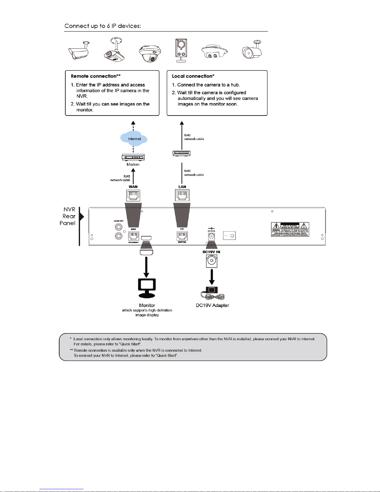
2) WAN
This port is used to connect your NVR to Internet via a RJ45 network cable.
3) HDMI
This port is used to connect the monitor which supports HDMI interface.
Note: Direct connection to the monitor which supports VGA or composite interface is not supported.
Please prepare a converter in advance.
4) LAN
This port is used to connect your NVR to our brand’s IP cameras locally.
5) Power IN
Connect the NVR to power with the regulated adapter (19V / 12V).
6) (Power switch) (for selected models only)
Switch to “–” to turn on the power, and “” to turn off the power.
7) RS485 (for selected models only)
Support RS485 devices
8) eSATA (for selected models only)
This port is used to connect a storage device supporting eSATA interface; for instance, an external hard disk
or a disk array.
Note: Please purchase a disk array supporting Linux system to ensure you NVR work properly.

CONNECTION
2
2. CONNECTION
2.1 Hard disk installation
Note: Product appearance may vary from the picture shown below , depending on the model you hav e.
Step1: Remove the top cover.
Step2: Find the hard disk bracket in the NVR, and place the compatible hark disk in the bracket.
Step3: With the PCB side facing up, connect the hard disk to the power connector and data connector.
Step4: Fasten the hark disk with the supplied screws, two for each side.
Step5: To install another hard disk, find the supplied hard disk brackets in the package, and fix them onto the NVR
base.
Step6: With the PCB side facing up, connect the hard disk to the power connector and data connector.
Step7: Then, put the hard disk in the bracket, and fasten it with the supplied screws, two for each side.
Step8: Replace the top cover and fasten the screws you loosened in Step1.
Note: Before remote firmware update, please install a HDD into your NVR first to make sure the
firmware update works properly.
Note: It’s not recommended to use a green HDD with your NVR to make sure it works properly.
2.2 Camera IP Configurations by LAN
2.2.1 AUTO Mode
Auto mode is to simplify the complicated network settings within three minutes. The connection mode of the LAN
port is “AUTO” by default. This mode is suitable when the LAN port of the NVR is connected to a hub.
Note: SETTING Path: (ADVANCED CONFIG) NETWORK LAN MODE.
CONNECTION
3

CONNECTION
4
The NVR will automatically configure the IP address of a camera connected by LAN if:
The connected IP camera is our brand’s IP camera.
Reset the IP camera to default value (the default IP configuration method of the camera is “DHCP”).
The camera is powered on before the NVR is powered on.
If the NVR doesn’t configure the IP address of your camera automatically as described above, your IP
camera might NOT be:
Our brand’s IP camera.
Set to “DHCP” as its default IP configuration method.
To solve this, use our brand’s IP camera, and reconfigure its IP address to 10.1.1.xx (xx ranges from 11 ~
253), in the same network segment as the NVR.
a) Select “ ” on the bottom of the screen, you’ll see the list of every connected IP camera with its connection
st
atus to this NVR and MAC addres
s.
b)
Select the IP address which is not us
ed, and select “SETUP”.
IP SEARCH
IP PORT MAC STATUS
10.1.1.12 88 00:0e:53:e5:9a:f1 CONNECTED TO CH1
10.1.1.13 88 00:0e:53:a6:91:18 BE CONNECTED TO CH2
10.1.2.14 88 00:0e:53:a5:9f:a2 UNUSED
10.1.1.15 88 00:0e:5 3:e1:4e:k5 CONNECTED TO CH3
10.1.1.16 88 00:0e:53:s5:3e:h6 CONNECTED TO CH4
10.1.1.17 88 00:0e:53:e6:4b:26 CONNECTED TO CH5
CONNECT
SETUP EXIT
c) Select “DHCP” in “NETWORK TYPE”.
d) Click “APPLY” and “EXI
T” to save your changes.
SETUP
NETWORK TYPE DHCP
IP 10.1.1.14
PORT 88
USER NAME admin
PASSWORD *****
NETMASK 255.0.0.0
GATEWAY 10.1.1.10
PRIMARY DNS 168.95.1.1
APPLY EXIT
e) The NVR will then detect the IP camera and display images soon.

CONNECTION
5
2.2.2 Static / DHCP Mode
Note: SETTING Path: (ADVANCED CONFIG) NETWORK LAN MODE.
When the LAN port of the NVR is connected to a router (not a hub), you can:
Choose “Static” when you know the network segment of your router.
For example, the IP address of your router of 192.168.0.1, and the network segment of your router will be
192.168.0.xx (xx is ranged from 2 ~ 254).
You can assign the IP address of the connected IP camera(s) by yourself.
Choose “DHCP” when your router supports the DHCP function, and you do not know the network segment of
your router.
The IP address of the connected IP camera(s) will be assigned by your router.

CONNECTION
6
2.3 Manual Connection Setup
To manually assign a channel to connect to the IP camera, select a corresponding “PROTOCOL” from the drop
down list first, click “URI” to enter the address of the camera, and enter its port number. There are four protocol
types available in the drop down list as follows: “AVTECH”, “ONVIF”, “RTSP OVER HTTP”, and “RTSP OVER
UDP”. If you are using AVTECH IP cameras, please select “AVTECH”; otherwise, choose the protocols your
cameras support.
ADVANCED CONFIG
CONNECTION CHANNEL PRO TOCOL URI PORT PATH CONFIG
CAMERA
CH1 AVTECH ://ip_office.ddns.eagleeyes.tw :80 / SETUP
DETECTION
CH2 ONVIF ://10.1.1.14 :88 / SETUP
ALERT
CH3 RTSP OVER HTTP ://10.1.1.30 :88 / SETUP
NETWORK
CH4 RTSP OVER UDP ://10.1.1.12 :88 / SETUP
DISPLAY
CH5 AVTECH ://10.1.1.16 :88 / SETUP
RECORD
CH6 AVTECH ://10.1.1.13 :88 / SETUP
NOTIFY
EXIT

USER INTERFACE
7
3. USER INTERFACE
3.1 Local
3.1.1 NVR Status
Key lock
Key unlock
Channel lock
Channel unlock
USB flash drive / device connected
No USB device connected
Timer record on
Timer record off
Overwrite on
Overwrite off
Sequence mode on
Sequence mode off
PTZ mode on
PTZ mode off
CPU loading
Network Status:
(WAN) Internet connected
(WAN) Internet disconnected
(WAN) Local connection
(LAN) Auto mode –Mbit/s
(LAN) Auto mode – Gbit/s
(LAN) DHCP / Static IP mode
(LAN) Camera disconnected
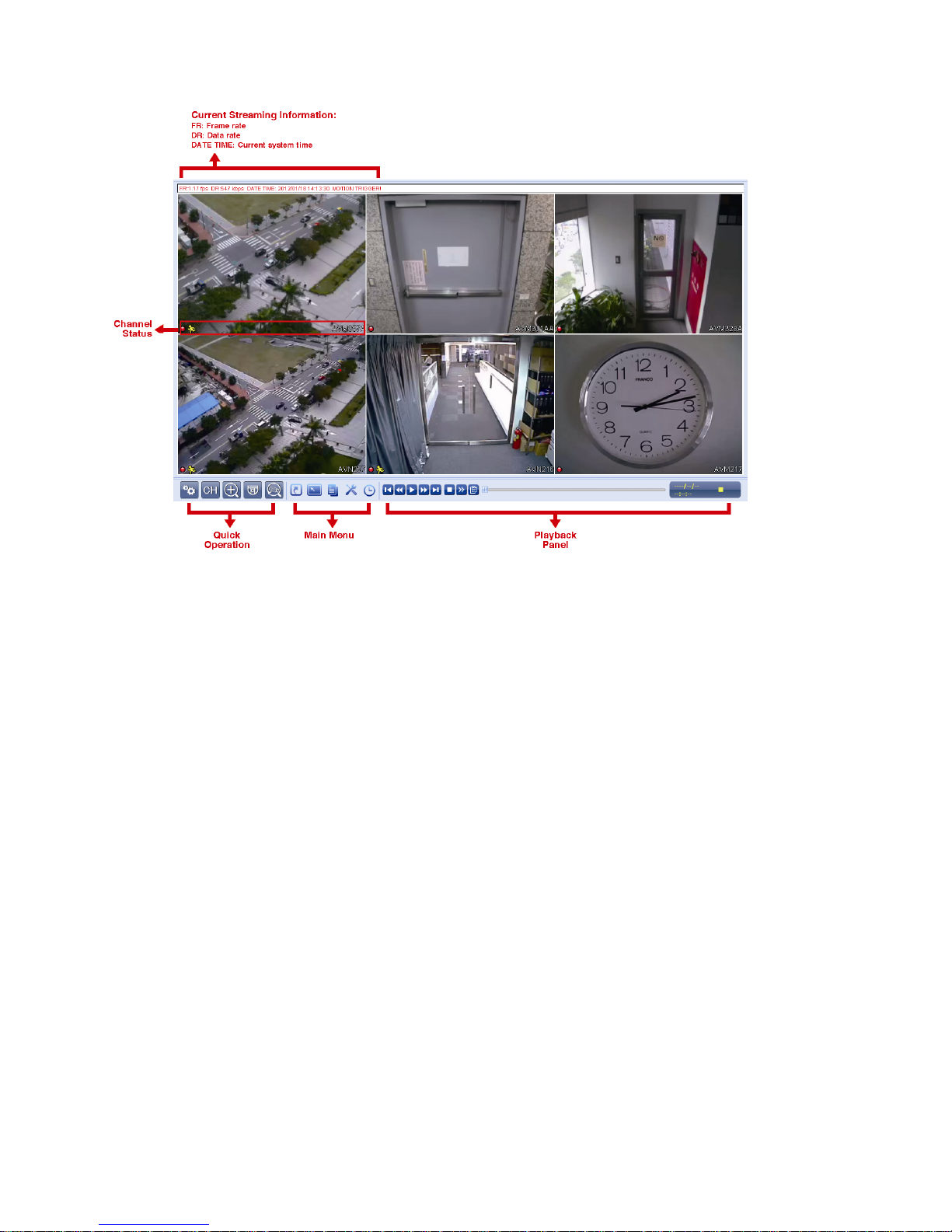
3.1.2 Channel Status
Auto search on
Auto search off
Original size Fit to screen
Live audio on
Audio off
Audio playback on
Audio playback off
Recording Human detection event Alarm event Motion event
Live information
Playback information
PTZ Control
USER INTERFACE
8
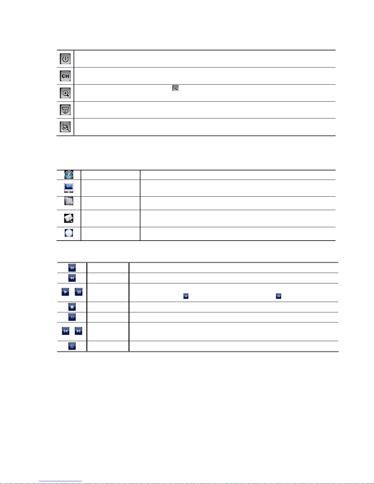
3.1.3 Quick Operation
For details, please refer to “5. QUICK OPERATION” at page 17.
Click to show the power off panel to either halt or reboot the system.
Click to show the channel switch panel and select the channel you want.
Switch to the channel you want first, and click
to enter the zoom-in mode. In this mode, click and drag the red frame on
the bottom left of the screen to move to the place you want to see.
Click to enter the PTZ mode and show the PTZ camera control panel.
Click to open the IP search window and check the current connection st atus of each channel.
3.1.4 Main Menu
For details, please refer to “6. MAIN MENU” at page 20.
QUICK START
Click to set the status display, image settings, and date & time.
SYSTEM
Click to set the system configurations.
EVENT INFORMATION
Click to enter the event search menu.
ADVANCED CONFIG
Click to set CONNECTION, CAMERA, DETECTION, ALERT, NETWORK, DISPLAY,
RECORD and NOTIFY.
SCHEDULE SETTING
Click to set record timer and event timer.
3.1.5 Playback Panel
Fast Forward Increase the speed for fast forward from 4X to 32X.
Fast Rewind Increase the speed for fast rewind from 4X to 32X.
/
Play / Pause
Click to play the latest recorded video clip immediately, and click again to pause.
In the pause mode, click
once to get one frame forward, and click to get one frame rewind.
Stop Click to stop the video playback.
Slow Playback Click once to get 1/4X speed playback, and click twice to get 1/8X speed playback.
/
Previous /
Next Hour
Click to jump to the next / previous time interval in an hour, for example, 11:00 ~ 12:00 or
14:00 ~ 15:00, and start playing the earliest event video clip recorded during this whole hour.
Quick Search Click to enter the quick search menu for specific record data search.
USER INTERFACE
9
3.2 Remote
 Loading...