

Page 1
Page 2
Page 3

1
CONTENTS
Section Page
Safety Symbol Description ..................................................................................................... i
Table of Contents ..............................................................................................................1
Introduction ....................................................................................................................2
Post Driver Safety ..............................................................................................................3
Rhino
®
Multi-Pro™ Operating Instructions ......................................................................................6
Starting the Engine .............................................................................................................6
Hot Restart ....................................................................................................................7
Driving a Post ..................................................................................................................8
Installing a Chuck Adapter .......................................................................................................9
Installing an Alternative Chuck ...................................................................................................9
Multi-Pro™ Maintenance ........................................................................................................10
Rhino
®
Multi-Pro™ Service Instructions .......................................................................................11
Servicing Cranksha and Piston .................................................................................................12
Service of the Hammer and Anvil ................................................................................................13
Regular Service Period .........................................................................................................18
Rhino
®
Multi-Pro™ Parts & Accessories List ...................................................................................20
Limited Warranty and Registration ............................................................................................28
Troubleshooting ..............................................................................................................29
Page 4

2
© 2016 Rhino Tool Company Inc., - All Rights Reserved
INTRODUCTION
Congratulations on your selection of the Rhino® Multi-Pro™ post
driver. We are certain that you will be pleased with your purchase. This post driver was built with the Honda GX35 engine.
Honda supplies its own owner’s manual that covers all the
operator and service procedures associated with the Honda
engine. Please read this manual as closely as you do the Rhino
manual. The success that you experience with this tool is dependent upon your knowledge and understanding of how to properly
operate and care for the Honda engine installed on your new post
driver.
As you read this manual, you will nd information preceded by a
NOTICE symbol. That information is intended to help you avoid
damage to your post driver, other property, or the environment.
We suggest you read the warranty information fully and understand its coverage and your responsibilities of ownership. Fill
out the warranty registration card or online registration to receive
Rhino® Limited Lifetime Impact Warranty. (See Page 28) Please
read and understand the Honda warranty policy. The Honda warranty is separate from the Rhino® warranty and is subject to its
own coverage conditions and responsibility requirements. The
warranty is a separate document and is included with the Honda
owner’s manual.
When your Rhino® post driver needs scheduled maintenance, the
technical service sta here at Rhino Tool Company is standing by
to assist you.. Our fully trained sta can ensure that you receive
the correct service kit or direct you to the nearest Rhino
Servicing Dealer.
The engine requires scheduled maintenance, keep in mind that
your Honda service dealer is fully equipped and specially trained
in servicing the Honda engine. Your Honda servicing dealer is
dedicated to your satisfaction, and will be pleased to answer your
questions and concerns.
Kindest Regards,
The Rhino Tool Company Team
Page 5

3
The Rhino® Multi-Pro™ gas powered
driver is designed to drive fence post,
ground rod, delineator post, vineyard post,
form pin, tent stake and other like items
into the ground.
Uses, other than those
intended, can result
in injury to the operator as well as those
around the operator. Damage to the driver
and to the surrounding area may result
as well. This post driver is intended for
use by professional installers. Never allow
children to operate this tool.
Most accidents can be prevented if you
follow all instructions in this manual and
on the post driver. The most common hazards are discussed below, along with the
best method to protect yourself and others.
UNDERGROUND
UTILITIES: Driving
a post into an underground utility can be
EXTREMELY DANGEROUS, exposing
the operator and those around to potentially life threatening danger. Damage to
surrounding property can also occur as a
result of a post being driven into an underground utility. Be absolutely certain that
you are aware of all underground utilities
in the area in which you intend to drive
posts. Ensure that a certied locating service has identied all underground utilities
prior to beginning your project. Failure to
do so can be catastrophic. Underground
utilities include but are not limited to:
Electric, Gas, Telephone, Water, Sewer,
TV Cable, Lawn Sprinklers, etc.
GASOLINE: Gasoline
is HIGHLY
FLAMMABLE and EXPLOSIVE. You
can be burned or seriously injured when
handling fuel.
EXHAUST: The ex-
haust from the engine
contains poisonous carbon monoxide gas
that can build up to dangerous levels in
closed areas. Breathing carbon monoxide
can cause unconsciousness or death. Never
run the engine in a closed or even partly
closed area where people may be present.
The engine exhaust
from this product contains chemicals
known to the State of California to cause
cancer, birth defects or other reproductive
harm.
ENGINE
MAINTENANCE:
Improperly maintaining the engine on this
power tool, or failure to correct a problem
before operation, can cause a malfunction in which you can be seriously hurt
or killed. In accordance with the engine
owner’s manual, always perform a preoperation inspection of the engine before
each use and correct any problem.
DRIVER
MAINTENANCE:
Improperly maintaining the driving
mechanism on this power tool, or failure
to correct a problem before operation, can
cause a malfunction in which you can be
seriously hurt or killed.
In accordance with this manual, always
perform a pre-operation inspection of the
driving mechanism before each use and
correct any problem.
IMPORTANT SAFETY INFORMATION
POST DRIVER SAFETY
!
WARNING
!
WARNING
!
WARNING
!
WARNING
!
WARNING
!
WARNING
!
WARNING
!
DANGER
!
CAUTION
Page 6
4
Do not lend or rent
your post driver without the instruction manuals. Be sure that
anyone using it understands the information contained in these manuals.
Do not use this post
driver for any purpose
other than driving posts into the ground.
Misuse may result in personal injury or
property damage, including damage to the
machine
Minors should never
be allowed to use this
power tool. Bystanders, especially children, and animals should not be allowed in
the area where it is in use.
NEVER let your
power tool run unat-
tended. When it is not in use, shut it o
and make sure that unauthorized persons
do not use it.
Do not operate this
post driver unless the
operator is wearing safety glasses, safety
shoes, hearing protection, gloves or any
other safety equipment advised by, ANSI,
NIOSH, OSHA, or any other safety regulatory agency, the employer or the owner
of this post driver.
Hearing protection is required as the
post driver emits noise at 100 dB level.
Bystanders should, at a minimum, wear
safety glasses and hearing protection while
in the presence of this power tool during
operation. If not wearing protective gear,
bystanders should keep a distance of 20
feet (6 m) from the post driver while in
operation.
Prolonged use of a
power tool (or other
machines) exposing the operator to vibra-
tions may produce white nger disease
(Raynaud’s phenomenon) or carpal tunnel
syndrome. These conditions reduce the
hand’s ability to feel and regulate temperature, produce numbness and burning
sensations and may cause nerve and circulation damage and tissue necrosis.
Not all factors contributing to white nger
disease are known, but cold weather,
smoking and diseases or physical condi-
tions that aect blood vessels and blood
transport, as well as high vibration levels
and long periods of exposure to vibration
are mentioned as factors in the develop-
ment of white nger disease.
In order to reduce the risk of white nger
disease and carpal tunnel syndrome, please
note the following:
• The Multi-Pro™ has been designed with
Rhino® CIS™ anti-vibration handles to
reduce the transmission of vibrations
created by the machine to the operator’s hands. An anti-vibration system is
recommended for those persons using
power tools on a regular or sustained
basis.
• The handle opposite the throttle handle
has been tted with an EPDM foam grip
further dampening vibrations.
• Wear gloves and keep your hands warm.
• Ensure that the EPDM foam and the
spring dampening system are in good
working condition.
IMPORTANT SAFETY INFORMATION
POST DRIVER SAFETY... continued
!
WARNING
!
WARNING
!
WARNING
!
WARNING
!
WARNING
!
WARNING
Page 7

• Ensure the post driver has no loose components. Loose components lead to high
vibration levels.
• Maintain a rm grip at all times, but do
not squeeze the handles with constant,
excessive pressure. Take frequent
breaks.
All of the above mentioned precautions
do not guarantee that you will not sustain
white nger disease or carpal tunnel syndrome. Therefore, continual and regular
users should closely monitor the condi-
tion of their hands and ngers. If any of
the above symptoms appear, seek medical
advice immediately.
DO NOT modify this
power tool in any way.
DO NOT put anything
other than a post into
the chuck on the driver.
DO NOT operate your
post driver unless it
is on a post to be driven. Operation of the
driver without it driving on a post could
damage the power tool.
SURROUNDINGS:
This power tool emits
noise at 100 Db, which may be disturbing
to animals and livestock. Ensure prior to
operation, that any livestock are cleared
from the operational area to prevent a situation in which startled livestock become a
safety hazard.
WARNING LABELS
If your post driver’s warning label is
marred or destroyed, replace it immediately. Simply call Rhino Tool Company
and we will send you a new warning label
at no expense to you.
End of Life Cycle
When your Rhino® gas powered driver is
coming to the end of its life cycle, destruction of the unit should to be conducted
according to international and local environmental regulations.
The gas powered post driver contains:
• Fuel
• Oil
• Rhino® Pro Series Lubricant
• Electric components
• Plastic-steel and aluminum components.
POST DRIVER SAFETY... continued
IMPORTANT SAFETY INFORMATION
!
WARNING
!
WARNING
!
DANGER
!
CAUTION
!
WARNING
!
DANGER
!
CAUTION
!
WARNING
!
DANGER
!
CAUTION
Rhino® Multi-Pro™
Specications imperial (metric)
Overall
Dimensions
10.75 x 17 x 26 in.
(273 x 432 x 660 mm)
Weight 44 lb (19.9 kg)
Engine
Conguration
4-stroke, 35.8 cc
Performance 1720 bpm
Fuel Unleaded Gas, US 86 Octane
(>Euro 91)
Fuel Capacity 0.67 US qt. (0.63 ltr)
Engine Oil SAE 10W-30
Lubricant Rhino
®
Pro Series Lubricant
Noise ≤ 100 Db
Vibration TBC
5
Page 8
6
Multi-Pro™ Operating Instructions
Your Rhino® Multi-Pro™ Gas Powered
Post Driver is an ecient and eective
power tool designed and developed to
tackle a dicult and time consuming task,
driving posts.
It is very important to understand that your
post driver is a very powerful machine.
With proper care and maintenance, your
Rhino® Multi-Pro™ will give you many
years of trouble free service.
You must read and understand your post
driver operating instructions before using
the post driver. It is also very important
that you make sure all operators are
trained to operate your post driver safely.
If you or any operator doesn’t understand
any of the instructions in this manual, call
Rhino Tool Company at 866-707-1808 or
309-853-5555 and we will assist you with
any questions you may have.
AVOID SERIOUS
INJURY OR DEATH
READ THIS MANUAL BEFORE
USING YOUR POST DRIVER.
Visually inspect your Multi-Pro™ Post
Driver before use. The interior of the
chuck tube should be checked for obstructions, damage or wear to the chuck tube
and anvil inside. The outer surfaces of the
driver should also be inspected for any
defects. Do not use the Multi-Pro™ if there
is any damage or wear until the damage or
wear is corrected and repaired.
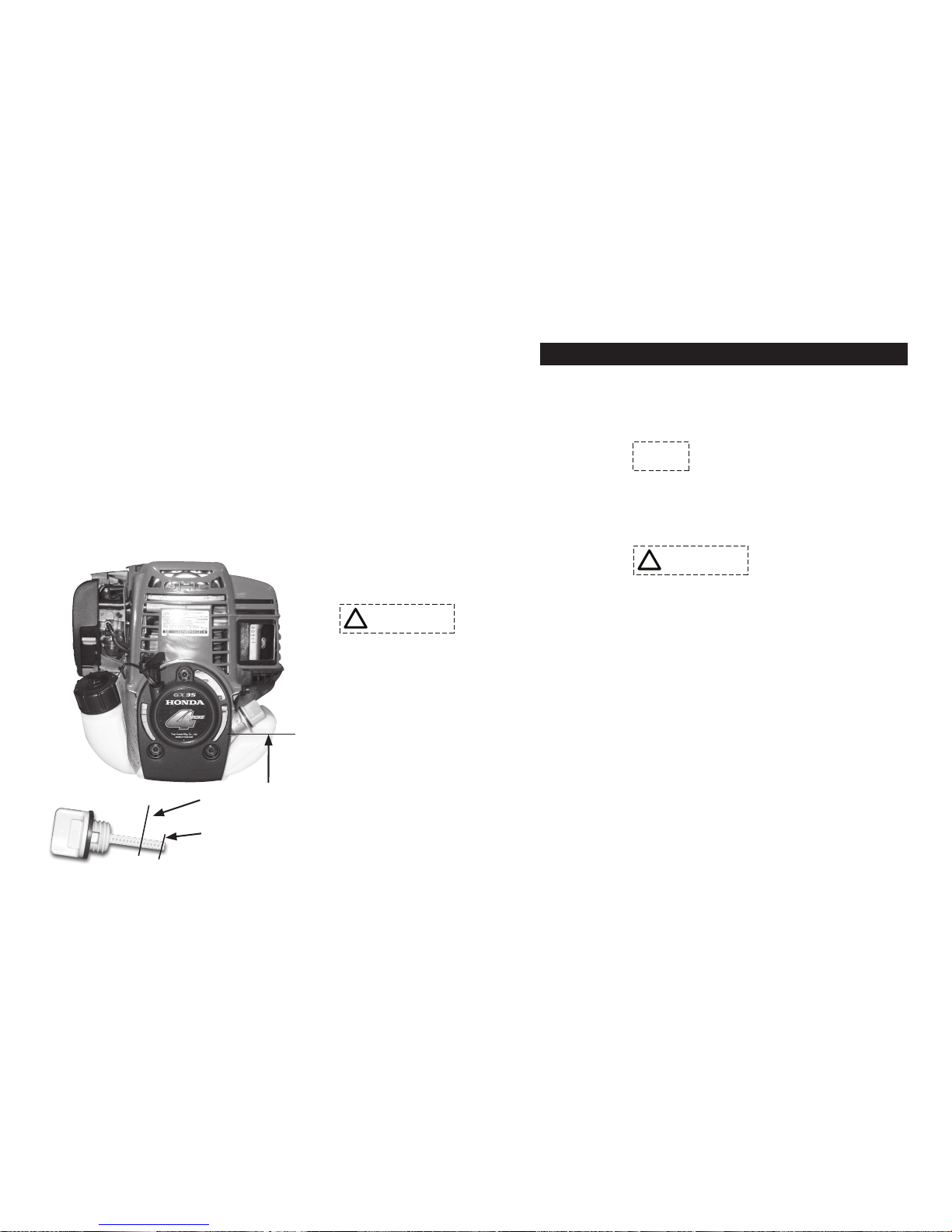
Check all uid levels, i.e. engine oil and
fuel and ll as needed as per manufacturer’s specications. (Fig. 1)
Proper oil level is essential
to the operation of the post
driver. Overlling of the oil will result in
loss of power and may cause permanent damage to the engine.
USE ALL RECOMMENDED
SAFETY EQUIPMENT.
Rest the driver on a solid surface, i.e.
tailgate, bench, or debris free solid ground
and posture your body in a safe position.
DO NOT start the driver anywhere but
an open, well-ventilated area. It is recommended that the Multi-Pro™ only be used
outdoors and never inside an enclosed
building.
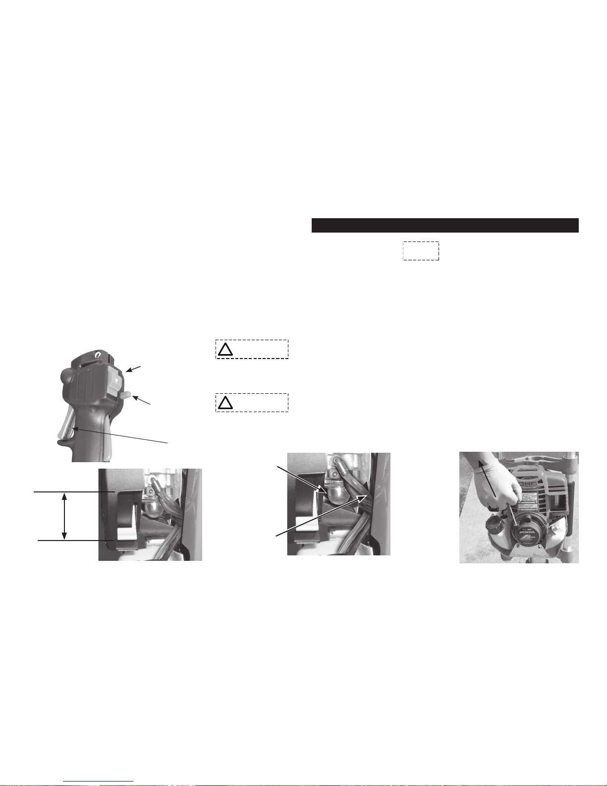
Starting the Engine:
To start a COLD engine, move the choke
lever to the CLOSED position (Fig. 3).
Lock the throttle into high idle position.
(Fig. 2) This is done by depressing the
!
WARNING
!
DANGER
!
CAUTION
IMPORTANT
NOTE
!
WARNING
!
WARNING
Fig. 1
Upper limit of
engine oil.
Lower limit of
engine oil is end
of dipstick.
Page 9
7
trigger and the high idle lock simultaneously. The throttle is now in the high idle
position.
To start a WARM engine, leave the choke
lever in the OPEN position and do not
lock the throttle into the high idle position.
Press the priming bulb repeatedly (Fig. 4)
until fuel can be seen in the clear-plastic
fuel return tube.
Slide thumb switch on throttle handle
down or into the ON position.
Grasp the starter grip lightly until you
feel resistance, then pull briskly in the
direction of the arrow as shown in Fig. 5.
Return the starter grip gently.
Do not extend the
starter rope to its full
length as it can cause damage the recoil
mechanism.
An operator should
never wrap the starter
rope around their hand. This will cause
serious injury.
Do not allow the starter grip
to snap back against the
engine. Return it gently to prevent
damage to the starter.
If the choke lever was moved to the
CLOSED position to start the engine,
gradually move it to the open position
as the engine warms up. As the engine
warms up also release the high idle lock
by slightly depressing the trigger and then
immediately releasing it. Use caution as
to not engage the clutch. Dry-Firing will
shorten the life of the post driver and
could cause damage.
Hot Restart If the engine is operated at
higher ambient temperatures, then turned
!
WARNING
!
DANGER
!
CAUTION
!
WARNING
!
DANGER
!
CAUTION
IMPORTANT
NOTE
Multi-Pro™ Operating Instructions... continued
Choke Closed
Choke Open
Fig. 3
Priming Bulb
Fuel Return
Line (clear
plastic tube)
Fig. 4
Starter Grip
Fig. 5
!
WARNING
!
DANGER
!
CAUTION
Thumb Switch
High Idle Lock
Trigger
Fig. 2
Page 10

8
o and allowed to sit for a short time, it
may not restart on the rst pull. If neces-
sary, use the following procedure:
IMPORTANT
SAFETY
PRECAUTION
Failure to follow instructions can result in
personal injury
Turn the engine switch to the OFF
position before performing the following
procedure. This will prevent the engine
from starting and running at maximum
speed when the throttle is in the MAX.
speed position. If the engine starts with
the throttle in the MAX. speed position,
the post driver will operate at maximum
power. This may result in personal injury
and damage to the post driver.
1. Turn the engine switch on the post
driver to the OFF position.
2. Move the choke lever to the OPEN
position.
3. Hold the throttle in the MAX speed
position.
4. Pull the starter grip 3 to 5 times.
Follow the STARTING THE ENGINE
procedure on the previous page and start
the engine with the choke lever in the
OPEN position.
Driving a Post
Holding the post driver with your left
hand on the foam grip and your right hand
on the throttle will position the driver to
direct the engine exhaust away from the
operator (Fig 6). (See Exhaust Warning)
Insert a post into the Multi-Pro™ making
sure the end of the post to be driven is in
the correct location on the ground. (Fig. 7)
Position the driver aligned and centered to
the post. If not aligned properly, damage
could be caused to the driver or the post.
Apply steady downward pressure to the
handles and apply enough throttle to engage the clutch and hammer.
Once you are condent that the post is
driving straight, apply full throttle to the
driver until the post is driven to the desired
depth.
Release the trigger dropping the engine
RPM back to idle before removing from
the post. When the engine has returned to
Multi-Pro™ Operating Instructions... continued
!
WARNING
Fig. 6
Fig. 7
Post Driver
Post
Right Wrong
Page 11

9
idle, proceed to the next post repeating the
previous method of driving a post.
Installing a Chuck Adapter
CHUCK SIZE: A
chuck or chuck adapter
that is too large for the post being driven
may damage the driver and may damage
the end of the post. Using a the appropriate chuck or chuck with adapter will align
the post to optimum striking position and
prevent damage to the driver. See the chart
below to specify the appropriate adapter
for your application. Chucks and chuck
adapters wear out and should be replaced
as needed. Inspect your driver’s chuck and
chuck adapters frequently.
The Multi-Pro™ is equipped with the
Rhino® Chuck-Lok™ Adapter System. It is
comprised of the master chuck, the locking nut and two-piece adapters.
ALWAYS HAVE
THE LOCKING
NUT IN PLACE WHEN DRIVING
POSTS: The Chuck-Lok
™
locking nut
should always be tightened onto the
master chuck to protect the chuck threads,
even when not using an adapter. Failure
to do so exposes the chuck to possible
damage.
The two-piece adapter design is a solution for the occasional flared post. Should
a post flare and lodge inside the chuck
when using the adapter, in most cases the
operator can loosen the locking nut letting
it slide down the post, then lift the driver
off the post. The operator can quickly
re-insert the adapter, secure them with the
locking nut and resume driving posts. See
Fig. 8 for steps for installing Chuck-Lok™
adapters.
Installing an Alternative Chuck
The Multi-Pro™ quick change design
allows the operator to quickly remove
the standard master chuck and install an
alternative chuck configuration for your
post driving application.
Multi-Pro™ Operating Instructions... continued
!
WARNING
!
WARNING
Type or Size of Post to be Driven (mm) Chuck/Accessory Required
Fiberglass T-Post 1¾" (44.45) Adapter
T-Post 1¾" (44.45) Adapter
5/8" (15.87) to 3/4" (19) Ground Rod 1" (25.4) Adapter
Tent Stake Tent Stake Chuck
Concrete Form Pin 1" Adapter
1" (25.4) to 1-5/8" (41.27) Post 1¾" (44.45) Adapter
1-7/8" Post 2" (50.8) Adapter
2"(50.8) to 2-3/8" (60.32) Post Master Chuck
1-1/2” (38.1) to 2-1/2” (63.5) Square Post and Square Post Sign Anchor Short Chuck and Drive Cap
1.2 - 4 lb Channel Post and Channel Post Sign Anchor Channel Chuck and Long Anvil
Note: Custom chucks may be available for your specic application contact Rhino Tool Company.
Page 12

10
Multi-Pro™ Operating Instructions... continued
Turn off the engine and allow it to cool.
Position the post driver on a work bench
or level surface. Using a 1/4" hex bit
socket wrench loosen and remove the 4
chuck bolts (p/n 300717-4) and lock washers (p/n 300750-4). Replace lock washers
if they are worn. Remove the chuck and
set it aside in a convenient place to store
until needed.
Align the alternate chuck to the bolt holes
on the lower body, taking into account the
position of slots or internal configuration
for the post to insert according to the operator side of the post driver. Insert bolts
through the lock washers and into the bolt
holes. Hand tighten bolts. Using a torque
wrench set to 132 lb/in (14.9 Nm) for
stainless bolts or 251 lb/in (28.4 Nm) for
black oxide bolts, tighten them in a cross-
ing pattern to the correct torque.
If alternative anvil parts are needed please
follow the instructions provided with alternative chuck kit.
If you do not see a chuck option for a
specific post, contact your Rhino Tool
Company representative to inquire if there
is an option available.
Maintenance of the Multi-Pro
™
NEVER REFUEL
WITH THE ENGINE
HOT OR RUNNING: Never refuel your
Multi-Pro™ with the engine hot or run-
ning as there is a possibility the ammable
fumes from the gasoline
can ignite, causing severe
injury and/or damage
to you/your Multi-Pro™
and the surrounding area.
Follow engine manufacturer’s instructions
for the refueling of the
engine.
DO NOT OPEN
CRANKCASE COV-
ER WHILE ENGINE IS RUNNING.
With each use check the engine oil level,
air lter, and all fasteners. If necessary,
add oil, clean or replace the air lter and
tighten any loose nuts, bolts, or any other
fastener. (See page 6 for engine oil level)
Change engine oil as per engine manu-
facturer’s specications. Dispose of used
oil in accordance with any local, state, or
federal regulations.
To help insure years of operation, wipe
down the Multi-Pro
™
with a clean cloth
after each days use.
Refer to the Service Instructions for
more detail regarding maintenance of
the Post Driver.
!
WARNING
!
WARNING
Fig. 8 - Hand tighten ONLY. No Tools.
Page 13

11
Multi-Pro™ Service Instructions
Following the service requirements for
the Multi-Pro™ will insure years of trouble
free operation. Always refer to the Honda
GX35 manual for maintenance and service
on the engine. The following instructions
are for the Rhino® Multi-Pro™ specically
with general instructions for the Honda
GX35. Before any service is preformed,
remove the spark plug wire from the spark
plug and ground it to the engine body
to prevent any accidental start-up of the
engine.
Each Use:
1. Check engine oil level. Use SAE 10W-
30 to top oil level o, if necessary.
Correct ll level shown on page 6.
2. Check condition of the engine air
cleaner. The air cleaner can be cleaned
or replaced. Consult your Honda engine manual for instructions.
3. Check crankcase lubrication by removing the Crankcase Cover. Instructions
for service are on page 12.
4. Check all engine and post driver fasten-
ers. Retighten to proper specications if
necessary. (See Bolt Torque Specica-
tions on page 27)
5. Check overall condition of post
driver before use. Any loose, broken
or worn parts should be replaced before
using post driver.
Every10hoursorrstmonthuseofa
new or rebuilt Multi-Pro
™
1. Change engine oil following the
requirement for the Honda GX35. Dispose of used oil according to all local,
state, and federal regulations.
2. Check all engine and post driver fasten-
ers. Retighten to proper specications if
necessary.
3. Check crankshaft and piston lubrication. (See page 12 for instructions.)
Every 3 months or 25 hours of use
1. Change engine oil following the
requirement for the Honda GX35. Dispose of used oil according to all local,
state, and federal regulations.
2. Replace air cleaner elements. This
should be performed more often if operated in dusty areas.
3. Check crankshaft and piston lubrication. (See page 12 for instructions.)
4. Check all engine and post driver fasteners. Retighten to proper torque specications if necessary. (See page 27)
Every 6 months or 50 hours of use
1. Change engine oil following the
requirement for the Honda GX35. Dispose of used oil according to all local,
state, and federal regulations.
2. Replace air cleaner elements. This
should be performed more often if operated in dusty areas.
3. Check crankshaft and piston lubrication. (See page 12 for instructions.)
4. Check all engine and post driver fasteners. Retighten to proper torque specications if necessary. (See page 27)
Every 12 months or 100 hours of use
1. Change engine oil following the
Page 14

12
requirement for the Honda GX35. Dispose of used oil according to all local,
state, and federal regulations.
2. Replace air cleaner elements. This
should be performed more often if operated in dusty areas.
3. Check crankshaft and piston lubrication. (See page 12 for instructions.)
4. Remove and service the hammer and
anvil. (See page 13 for instructions.)
5. Check all engine and post driver fasteners. Retighten to proper torque specications if necessary. (See page 27)
Servicing Crankshaft and Piston
Lubrication
(Fig. 9) The crankcase cover (p/n 300132)
is designed for easy, “no tool” inspection
and maintenance. To remove the cover,
grip it tightly with your hand and twist it
left (counter-clockwise.) Use caution not
to lose or damage the O-ring Seal (p/n
301617).
DO NOT OPEN
CRANKCASE COV-
ER WHILE ENGINE IS RUNNING
DO NOT USE A
HAMMER OR
WRENCH TO
LOOSEN THE COVER AS IT MAY
CAUSE DAMAGE TO THE DRIVER.
Visually inspect the color and amount
of Rhino
®
Pro Series Lubricant inside
the crankcase. There should be a ring of
Rhino® Pro Series Lubricant collected to
the wall inside the crankcase. Should the
depth of the ring from the wall inward
measure 1/8" (3mm) or less (Fig. 10) this
indicates the Rhino
®
Pro Series Lubricant
is low. The maximum level should not be
more than 1/4" (6mm). If the amount of
Rhino® Pro Series Lubricant appears to be
low, add a small amount of Rhino® Pro Series Lubricant. Use only Rhino approved
Rhino® Pro Series Lubricant (p/n 300500.)
DO NOT OVER-
FILL RHINO® PRO
SERIES LUBRICANT AS IT CAN
DAMAGE THE DRIVER AND THE
HONDA ENGINE.
Multi-Pro™ Service Instructions... continued
Fig. 9 - Crankcase Cover
!
WARNING
!
DANGER
!
CAUTION
!
WARNING
!
DANGER
!
CAUTION
Fig. 10 - If ridge of Rhino
®
Pro Series
Lubricant measures 1/8″ or less, add a
small amount. At maximum level it should
measure 1/4".
!
WARNING
!
DANGER
!
CAUTION
Page 15

13
If the Rhino® Pro Series Lubricant appears
burnt or has an odor of burnt lubricant it
should be removed and the post driver
needs further maintenance. This is detailed
in the section titled “Service of the Hammer and Anvil.”
In the event of complete removal of old
Rhino® Pro Series Lubricant and adding
fresh Rhino® Pro Series Lubricant (Fig.
11) rotate the crankshaft with connecting
rod and crank pin until the crank pin is in
the 12:00 position, then add Rhino® Pro
Series Rhino Pro Series Lubricant
(p/n 300500). The level of Rhino® Pro
Series Lubricant should be to the bottom
of the crank pin. When the required service has been performed in the crankcase,
inspect the o-ring seal and replace it on the
crankcase cover. Position the crankcase
cover on the Multi-Pro™ body carefully
to start the threads and once in the thread
groove, with your hand twist to the right
(clock-wise) until it is securely in contact
with the post driver body.
HAND TIGHTEN
ONLY. DO NOT
OVERTIGHTEN. Do not use tools, such
as a hammer or wrench, to tighten the crankcase cover as it will damage the driver.
Service of the Hammer and Anvil
The tools required for servicing the hammer and anvil are, a 9/64″ hex wrench, a
1/4″ hex wrench, a 7/8″ deep well socket
with handle, a torque wrench that reads
in inch/pounds, and Loctite primer and
threadlocker.
Remove the crankcase cover (see crankcase
cover CAUTION on page 12) and clean
out any old Rhino
®
Pro Series Lubricant
from inside the crankcase.
Remove the four (4) chuck bolts (p/n
300717-4) and disconnect the chuck.
Remove the four (4) lower bolts (p/n
300701-4) from the lower driver body and
the four (4) bolts (p/n 300715-4) from the
upper handle bracket. Use caution as the
handle tubes have four (4) anti-vibration
springs (p/n 610010-4) installed and under
tension. Grasping the upper handle bracket
pull it directionally away from the driver
body to create a separation between them.
While separated, lift and remove the upper
driver body assembly (p/n 301016) from
the post driver assembly and set aside.
Multi-Pro™ Service Instructions... continued
Fig. 12 - View of the Lower Driver Body
Assembly when removed from the post
driver. 301115
!
WARNING
!
DANGER
!
CAUTION
Fig. 11 - After completely cleaning out old
lubricant, add new Rhino
®
Pro Series Lubricant till level with the bottom edge of the
crank pin head.
Rotate
Crankshaft
until crank pin
is in 12:00
position.
Page 16

14
Observe the lower driver body, it should
appear as shown in Fig. 12. The anvil oring retainer (p/n 301115) will sometimes
be removed with the lower driver body or
remain in place at the base of the cylinder
of the upper driver body.
Remove the anvil o-ring cup (p/n 301095)
and the anvil (p/n 301165). This can be accomplished by pushing a hammer handle
into the chuck tube from the opposite side.
When the parts are removed, note the order and disassemble for inspection. Check
the anvil for damage. The anvil o-ring (p/n
301615) should be replaced at this time.
Clean the anvil and carefully replace the
anvil o-ring. (Fig 13) shows an anvil with
the o-ring in place.
Inspect inside the sleeve in the lower body
for damage. If the ledge that supports the
anvil o-ring cup is damaged, replace with
new sleeve (p/n 301038.)
Remove the large retainer o-ring seals
(p/n 301614-2) and the large retainer (p/n
301105) from the anvil o-ring cup. Inspect
the large retainer. The large retainer oring seals should be replaced at this time.
Replace the large retainer if there are any
signs of damage or excessive wear.
The anvil o-ring retainer (p/n 301115) can
be removed from the end of the cylinder in
the post driver body by hand. Use caution
as it can become sharp with use of the
driver. Remove the hammer (p/n 301085),
piston and connecting rod assembly
(p/n 301075) by removing the crank pin
(p/n 300050). Access to the crank pin is
achieved by removing the crankcase cover
(p/n 300132), which is described in the
section titled “Servicing Crankshaft and
Piston Lubrication.” Remove the crank pin
using the 7/8″ deep well socket.
The crank pin has
LEFT-HAND
THREADS. Use caution stabilizing
the connecting rod and crankshaft (p/n
300040) to avoid damaging them. Use a
small wood or plastic block to keep the
crankshaft from rotating. When the crank
pin is removed, the piston, connecting rod,
and hammer can be removed by pushing
the connecting rod down into the cylinder
until it can be removed from the bottom
of the post driver body. Note position of
the hammer. The small end of the hammer
is toward the anvil as shown in (Fig. 14.)
Clean and inspect the hammer for damage.
The hammer o-ring seal (p/n 301610-2)
should be replaced at this time.
Multi-Pro™ Service Instructions... continued
Fig. 14 - Small end of Hammer is toward
the anvil.
Fig. 13 - Anvil with O-ring in place.
!
WARNING
!
DANGER
!
CAUTION
Page 17

Clean and inspect the piston and connecting rod. Insert the crank pin into the
bearing on the connecting rod. If there
is excessive play between the two, the
connecting rod and possibly the crank pin
should be replaced. Check the movement
in the bearing in the piston side. If there is
excessive play the piston assembly should
be replaced. The piston o-ring seal (p/n
301610-2) should be replaced at this time.
(See Fig. 15.)
Clean and inspect the cylinder and
crankcase for any damage or wear.
Replace any damaged parts. Lubricate the
cylinder, piston, and connecting rod with
Rhino
®
Pro Series Lubricant (p/n 300500.)
Insert the connecting rod, of piston
assembly, into the cylinder. Push the
piston up the cylinder until the bearing in
the connection rod aligns with the threaded hole for the crank pin. Apply Loctite
Primer N 7649 to the threads in the
crankshaft and crank pin. Let the Primer
dry completely. Apply a line of Loctite
243 Threadlocker to the threads on the
crankshaft. Insert the crank pin through
the bearing and start the threads into the
crankshaft by hand. Use caution holding
the connecting rod and crankshaft (p/n
300040). The connecting rod and crankshaft can be damaged. Use a small wood
or plastic block to keep the crankshaft
from rotating.
!
WARNING
!
DANGER
!
CAUTION
These are LEFTHAND THREADS.
Tighten the crank pin using the 7/8″ deep
well socket. Torque to 360 inch/pounds
(40.6 Nm). Add Rhino® Pro Series
Lubricant (p/n 300500) to the crankcase to
the level shown in Fig. 11. (See Caution:
DonotoverllRhinoProSeriesLubricant on page 12)
If Lubricant has been completely removed,
add 2.75 oz or 81.32 ml of Rhino
®
Pro
Series Lubricant or until level with the
bottom of the crankpin head. Close the
crankcase by placing the crankcase cover
o-ring seal onto the crankcase cover. Place
the crankcase cover onto the post driver
body, start the thread, and twist to the right
(clockwise) with your hand until it is
secure against the post driver body. (See
Caution: Do Not Overtighten on page
13)
Lubricate the hammer with Rhino® Pro
Series Rhino Pro Series Lubricant. Insert
the hammer into the cylinder, taking note
of the small end toward the anvil as shown
in Fig. 14. Push the hammer into the
cylinder making room to insert the anvil
o-ring retainer. Apply Rhino® Pro Series
Lubricant to the anvil o-ring retainer and
place the small end into the cylinder. The
Rhino® Pro Series Lubricant should hold it
in place. Lubricate with Rhino® Pro Series
Lubricant and assemble the large retainer
and the two (2) large retainer o-ring seals
in the order shown in (Fig. 16 on next
page) and assemble into the anvil o-ring
cup.
15
Multi-Pro™ Service Instructions... continued
Fig. 15 - Piston with Connecting Rod and
O-ring Seal in place.
Page 18

16
Multi-Pro™ Service Instructions... continued
THE LARGE RADI-
US OF THE LARGE
RETAINER MUST BE POSITIONED
UPWARD FACING THE HAMMER
OR IT WILL CAUSE DAMAGE TO
THE DRIVER.
Clean and inspect the lower driver body
(p/n 301032) for any damage or excessive wear. Replace if necessary. Lubricate
inside of the sleeve of the lower body with
Rhino
®
Pro Series Lubricant. Lubricate the
anvil with Rhino® Pro Series Lubricant.
Insert the anvil with new anvil o-ring into
lower body, making certain that the anvil
is seated into the lower body. Insert the anvil o-ring cup into the lower body. Discard
the used O-ring cup, O-ring (p/n 301618)
and Gasket. Replace with new O-ring cup
and Gasket. The O-ring is obsolete and no
longer needed. The assembly should look
like Fig. 12, but without the o-ring.
All threads on the bolts and in the body
and lower body need to be clean and free
of any dried threadlocker or debris. Apply
Loctite Primer N 7649 to the external and
internal threads. The primer must be dry
before assembly. Apply the gasket to the
lower body assembly by removing the
paper backing and exposing the adhesive
on one side. With the adhesive on one
side. With the facing the lower body, press
gasket into place making sure the bolt
holes are lined up. Apply threadlocker
to the threaded holes on the body. The
threadlocker needs to be applied starting
at the bottom of the threaded hole and
apply a bead of threadlocker up to the top
of the thread. With the gasket in place on
the lower body, remove the paper backing
on the other side of the gasket. Grasp the
Upper Handle Bracket and pull toward
the Upper Handle, depressing the upper
Springs. Seat the Lower Body onto the
upper Body making sure the bolt holes
are aligned. Gently let the upper handle
bracket slide back into place. Place the
lock washers onto the lower body bolts.
The lock washers are a two (2) piece design. Do not separate the parts of the lock
washer. Insert and start by hand the four
(4) lower body bolts through the lower
body and into the body. Use a 1/4" hex
wrench to tighten the bolts in a crossing
pattern. Check for any misalignment or
binding when joining the parts. Do not use
excessive force. Using a torque wrench
set to 132 lb/in (14.9 Nm) for stainless
bolts or 251 lb/in (28.4 Nm) for black
O-ring
O-ring
Anvil
O-ring
Cup
Anvil
with
O-ring
Large Retainer
Large Radius (up)
Fig. 16 - Insert O-ring into Anvil O-ring
Cup, then insert Large Retainer (with large
radius up), then insert other O-ring.
!
WARNING
!
DANGER
!
CAUTION
Page 19

17
Multi-Pro™ Service Instructions... continued
oxide bolts, tighten to the correct torque.
Hand thread the four (4) upper handle
bolts through the handle bracket and into
the body. Do not use lock washers on the
upper handle bolts. Use a 1/4" hex wrench
to tighten the bolts in a crossing pattern.
Using a torque wrench set to 132 lb/in
(14.9 Nm) for stainless bolts or 251 lb/in
(28.4 Nm) for black oxide bolts, tighten
to the correct torque.
Apply Loctite Primer N 7649 to the
threaded holdes in the lower body and to
the chuck bolts. Let the primer dry before
assembly. Apply the threadlocker to the
threaded holes in the lower body. The
threadlocker needs to be applied starting at
the bottom of the threaded hotes and apply
a bead of threadlocker up to the top of the
thread. Insert the chuck bolts into the lock
washers. The lock washers are two (2)
piece design. Do not separate the parts of
the lock washer. Insert and start the four
(4) chuck bolts through the chuck and into
the lower body. Use a 1/4" hex wrench to
tighten the bolts in a crossing pattern. Using a torque wrench set to 132 lb/in (14.9
Nm) for stainless bolts or 251 lb/in (28.4
Nm) for black oxide bolts tighten to the
correct torque.
To clean and lubricate the anti-vibration
handle springs loosen the two bolts
located in the recesses of the top handle
assembly (p/n 301222) until the upper
handle and handle collars are free from
the upper handle bracket. Slide the lower
handle downward to expose the lower
springs. Clean the springs, upper handle
bracket cups, and upper and lower handle
collars with acetone or cleaning solvent.
Apply Rhino lubricant to springs, right
and left collars of the lower handle, top
cups of the upper handle bracket, and upper handle collars. Slide the lower handle
assembly back up into position. Apply
Loctite Primer N 7649 to the handle bolts
and the threaded holes in the handles. Let
the primer dry. The threadlocker needs
to be applied starting at the bottom of
the internal thread and apply a bead of
threadlocker up to the top of the thread.
Insert the springs into the upper handle
bracket cups. Then insert the upper handle
with collars on top of the springs depressing them into the handle bracket cups and
tighten the bolts to secure the handle into
place. Using a torque wrench set to 132 lb/
in (14.91 Nm) for stainless bolts or 251 lb/
in (28.4 Nm) for black oxide bolts, tighten
to the correct torque.
Perform a visual check of the post driver.
Reconnect the spark plug wire to the spark
plug. Check that the engine has the proper
amount of oil. Start the engine using the
proper procedure and test the post driver.
Page 20

18
Regular Service Period
Item
Each Use
First Month Or
10 Hours
Every 3 Months
Or 25 Hours
Every 6 Months
Or 50 Hours
Every 12 Months
Or 100 Hours
Refer to
Page
Engine Oil
Check Level
X
Page 6
Engine Oil
Change
X X
Page 6
Air Cleaner
Check
X
See Honda
Engine Manual
Air Cleaner
Clean
X (1)
See Honda
Engine Manual
Air Cleaner
Replace
X
See Honda
Engine Manual
Crankcase
Lubrication Check
X
Page 12
Check Engine and
Post Diver
Fasteners
X
Page 23
Remove, Service,
Piston Hammer and
Anvil
X
Page 13
Other Honda Engine
Maintenance Schedule
See Honda
Engine Manual
(1) Service more frequently when used in dusty areas.
Multi-Pro™ Service Instructions... continued
Page 21

19
NOTES
Page 22

20
Rhino® Multi-Pro™ Parts and Accessories List
4
4
4
56
10
11
3
5
6
8
9
7
2
13
12
141516
17
18
19
21
22
20
20
23
4
24
25
26
26
28
293031
1
27
4
6
6
Multi-Pro™ Standard Conguration
*Please refer to page 24 for Multi-Pro XA parts and accessories
Page 23

21
Rhino® Multi-Pro™ Parts and Accessories List
No. P/N Description
1 300712 Ground Bolt
2 301016 Body Assembly with Cylinder and Bearings
3 301222 Top Handle Assembly
4 300715-4 Pro Series Handle Bolt (qty. of 4)
5 301221-2 Handle Collar Set (qty. of 2)
6 610010-4 Handle Springs (qty. of 4)
7 300214 Top Handle Bracket
8 301075 Piston and Connecting Rod Assembly
9 301610-2 Piston and Hammer O-ring Seal Set (qty. of 2)
10 301085 Multi-Pro™ Hammer
11 301115 Multi-Pro™ Anvil O-ring Retainer
12 301614-2 Large Retainer O-ring Seal Set (qty. of 2)
13 301105 Multi-Pro™ Large Retainer
14 301095 Multi-Pro™ Anvil O-ring Cup
15 301165 Anvil (See page 27 for Extended Anvil.)
16 301615 Multi-Pro™ Anvil O-ring Seal
17 301710 Multi-Pro™ Body Gasket
18 301038 Multi-Pro™ Sleeve for Lower Body
19 301032 Multi-Pro™ Lower Body
20 300750-4 Multi-Pro™ Lock Washers (qty. of 4)
21 300701-4 Lower Body Bolt Set (qty. of 4)
No. P/N Description
22 301158 Multi-Pro™ Master Chuck
23 300717-4 Multi-Pro™ Chuck Bolt Set (qty. of 4)
24 301920 Chuck-Lok
™
Locking Nut (1 per driver)
25 300221 8.5" (216mm) EPDM Foam Grip (1 per driver)
26 301232 Pro-Series Side Handle Assembly
27 300250 Throttle Control Assembly
28 301233 Lower Handle Assembly
29 300900 Chuck-Lok
™
System 1" (25.4 mm) Adapter
30 300895 Chuck-Lok
™
System 1¾" (44.45 mm) Adapter
31 300902 Chuck-Lok
™
System 2" (50.8 mm) Adapter
Page 24

Rhino® Multi-Pro™ Parts and Accessories List
2
41
38
38
39
40
42
43
44
45
46
47
2
48
47
22
!
WARNING
!
DANGER
!
CAUTION
IMPORTANT
NOTE
Disassembly of the Crankcase will break the tamper
evident seal, thereby voiding the warranty on the driver
Page 25

Rhino® Multi-Pro™ Parts and Accessories List
No. P/N Description
2 301016 Body Assembly with Cylinder and Bearings
38 300782-4 Retaining Ring Set for Crankshaft & Clutch Drum with Pinion Gear
(qty. of 4)
39 300200 Gear
40 300730 Machine Key
41 300700-4 Clutch Housing Bolt Set (qty. of 4)
42 300025 Clutch Housing with Bearings
43 300120 Clutch Drum with Pinion Gear
44 300132 Pro-Series
™
Crankcase Cover - Threaded
45 301617 O-ring Seal for Pro-Series
™
Crankcase Cover - Threaded
46 300050 Crank Pin (Left Hand Threads)
47 300704-6 Crankcase Bolt Set (qty. of 6)
48 300040 Crankshaft
23
Page 26

Rhino® Multi-Pro™ Parts and Accessories List
13143216
17
19
18
21 20
34
2023
24
293031
Multi-Pro™ XA Lower Body Conguration*
12
*Please refer to the Multi-Pro Standard Conguration for parts information on the upper portion of the Multi-Pro XA.
24
Page 27

No. P/N Description
Multi-Pro XA™ ONLY
11 301115 Multi-Pro™ Anvil O-ring Retainer
12 301614-2 Large Retainer O-ring Seal Set (qty. of 2)
13 301105 Multi-Pro™ Large Retainer
14 301095 Multi-Pro™ Anvil O-ring Cup
16 301615 Multi-Pro™ Anvil O-ring Seal
17 301710 Gasket
18 301038 Multi-Pro™ Sleeve for Lower Body
19 301032 Multi-Pro™ Lower Body
20 300750-4 Multi-Pro™ Lock Washers (qty. of 4)
21 300701-4 Lower Body Bolt Set (qty. of 4)
23 300717-4 Multi-Pro™ Chuck Bolt Set (qty. of 4)
24 301920 Chuck-Lok
™
Locking Nut (1 per driver)
29 300900 Chuck-Lok
™
System 1" (25.4 mm) Adapter
30 300895 Chuck-Lok
™
System 1¾" (44.45 mm) Adapter
31 300902 Chuck-Lok
™
System 2" (50.8 mm) Adapter
32 301169 Multi-Pro Extended Anvil
34 301420 Multi-Pro
™
Extended Master Chuck
Rhino® Multi-Pro™ Parts and Accessories List
25
Page 28

No. P/N Description
49 300180 Shroud
50 300181-2 Grommet (qty. of 2)
51 300190-2 Shroud Spacer (qty. of 2)
52 300706-2 Shroud Bolt (qty. of 2)
53 300705-2 Lower Shroud Bolt (qty. of 2)
300240 Honda GX35 Engine
Honda Engine Parts are Available from Your Local Honda Dealer
300805 Safety Label and Tag Set
301801 Multi-Pro
™
Operating, Safety, and Parts Manual
49
51
51
53
50
50
Rhino® Multi-Pro™ Parts and Accessories List
52
26
Page 29

Rhino® Multi-Pro™ Parts and Accessories List
No. P/N Description
Accessories
31 300902 Chuck-Lok
™
System 2" (50.8mm) Adapter
30 300895 Chuck-Lok
™
System 1¾" (44.4mm) Adapter
29 300900 Chuck-Lok
™
System 1" (25.4mm) Adapter
24 301920 Chuck-Lok
™
Locking Nut (1 required)
301159 Multi-Pro
™
Slotted Chuck
301169 Multi-Pro
™
Extended Anvil
301175 Multi-Pro™ U-Channel Drive Kit (includes 301159, 301169)
301155 Multi-Pro
™
Tent Stake Chuck
301400 Large Chuck Adapter (required for all large chucks) Plate*
301171 Multi-Pro
™
Square Tube Chuck
300932 Drive cap for 1¾" (44.4mm) Square Tube**
300933 Drive cap for 2" (50.8mm) Square Tube**
300934 Drive cap for 2¼" (57.15mm) Square Tube**
300935 Drive cap for 2½" (63.5mm) Square Tube**
301403 Multi-Pro
™
3½" Round Chuck Assembly***
301405 Multi-Pro
™
4" Round Chuck Assembly***
301415 Multi-Pro
™
3" Square Chuck Assembly***
301414 Multi-Pro
™
3" Round Chuck Assembly***
34 301420 Multi-Pro
™
Extended Master Chuck
No. P/N Description
301422 Multi-Pro
™
XA Square Tube Chuck
301000 ¼" Long Arm Hex Key
300500 Rhino
®
Pro Series Lubricant
300506 Rhino
®
Pro Series Lubricant - 12-pack
301509 Multi-Pro
™
Service Kit
Bolt Torque Specications
4 300715-4 Pro Series Handle Bolts (qty. of 4) - 132 lb/in (14.91 Nm)
21 300701-4 Lower Body Bolts (qty. of 4) - 251 lb/in (28.3 Nm)
23 300717-4 Multi-Pro™ Chuck Bolt Set (qty. of 4) - 251 lb/in (28.3 Nm)
41 300700-4 Clutch Housing Bolt (qty. of 4) - 95.0 in/lbs (10.73 Nm)
46 300050 Crank Pin (Left Hand Threads) - 360.0 in/lbs (40.6 Nm)
47 300704-6 Crankcase Bolt (qty. of 6) - 75.0 in/lbs (8.5 Nm)
52 300706-2 Shroud Bolt (qty. of 2) - 56.4 in/lbs (6.37 Nm)
53 300705-2 Shroud Bolt - Self Tapping (qty. of 2) - 56.4 in/lbs (6.37 Nm)
*Requires 301169 Multi-Pro
™
Extended Anvil
**Requires 301171 Square Tube Chuck of 301422 XA Square Tube Chuck
***Requires 301400 Large Chuck Adapter Plate
27
Page 30

Warranty: Rhino Tool Company, Inc. (“Rhino”) warrants
to the original purchaser, purchasing the Equipment in new
condition, in original packaging from an authorized dealer
that its Gasoline Powered
Post Driver will be free from
defects in workmanship and
materials (the “Limited Warranty”). The Limited Warranty
shall survive for the lifetime
of the product with respect to the Hammer and Anvil components
and for twelve (12) months with regard to all other components,
excluding the Honda GX35 engine for which Rhino provides no
warranty and for which the warranty provided by American Honda
Motor Co., Inc. shall be the sole warranty applicable thereto. This
Limited Warranty is non-transferable.
For Warranty Claims contact your dealer or distributor. Proof of
purchase date and serial number is required. In the event of a
warranty repair, the post driver should be returned to a Registered
and Warranty Authorized Rhino Servicing Dealer. Rhino’s obligation under this Limited Warranty is expressly limited to the repair
or replacement, at Rhino’s election, of such defective Gasoline
Powered Post Driver, which is proved to be defective upon inspection by a Rhino-certied/authorized technician.
This Limited Warranty does not extend to a Gasoline Powered
Post Driver which has been subject to misuse, neglect, or accident, nor does it extend to any Gasoline Powered Post Driver
which has been repaired, altered, or serviced by unauthorized
persons. This Limited Warranty does not cover any damage or
adjustments required to any Gasoline Powered Post Driver if such
damage or adjustment is caused by the use of supplies, parts, or
attachments not sold or approved by Rhino
EXCEPT AS OTHERWISE PROVIDED HEREIN, RHINO DISCLAIMS ALL OTHER WARRANTIES, EXPRESS OR IMPLIED,
INCLUDING, BUT NOT LIMITED TO THE IMPLIED WARRANTIES OF MERCHANTABILITY AND FITNESS FOR A PARTICULAR PURPOSE. UNDER NO CIRCUMSTANCES SHALL RHINO BE LIABLE FOR ANY LOSS OF BUSINESS, REVENUES,
OR PROFIT OR OTHER INDIRECT, INCIDENTAL, SPECIAL OR
CONSEQUENTIAL DAMAGES OR LOSS ARISING OUT OF ANY
DEFECTS IN OR PERFORMANCE OF THE GASOLINE POWERED POST DRIVER, HOWSOEVER CAUSED.
To register your product:
Fill out and mail in registration card supplied with post driver
Or online visit:
http://rhinotool.com/contact-support/warranty-information/
Rhino® Limited Lifetime Impact Warranty
Gasoline Powered Post Drivers
W
A
R
R
A
N
T
Y
L
I
F
E
T
I
M
E
28
Page 31

Page 32

 Loading...