

Page 1
FORM NO. EXP11-773
PACKAGE
HEAT P
UMP UNITS
*Unit shown with
optional louver
panels installed.
Featuring Industry Standard R-410A Refrigerant
SJNL- HIGH EFFICIENCY SERIES
NOMINAL SIZES 5-6 TONS [17.6-21.1 kW]
Page 2

2
TABLE OF CONTENTS
Introduction ................................................................................................3-4
Model Identification Options ..........................................................................5-6
General Data
SJNL- Series ..............................................................................................7
General Data Notes ........................................................................................8
Performance Data
SJNL- Series ..........................................................................................9-10
Airflow Performance
SJNL- Series ........................................................................................11-12
Electrical Data
SJNL- Series ............................................................................................13
Units with Heater Kits
SJNL- Series ............................................................................................14
Selection Procedure ......................................................................................15
Dimensional Data ....................................................................................16-20
Accessories ............................................................................................21-30
Mechanical Specifications ..............................................................................31
Typical Wiring ..........................................................................................32-33
Page 3
3
INTRODUCTION
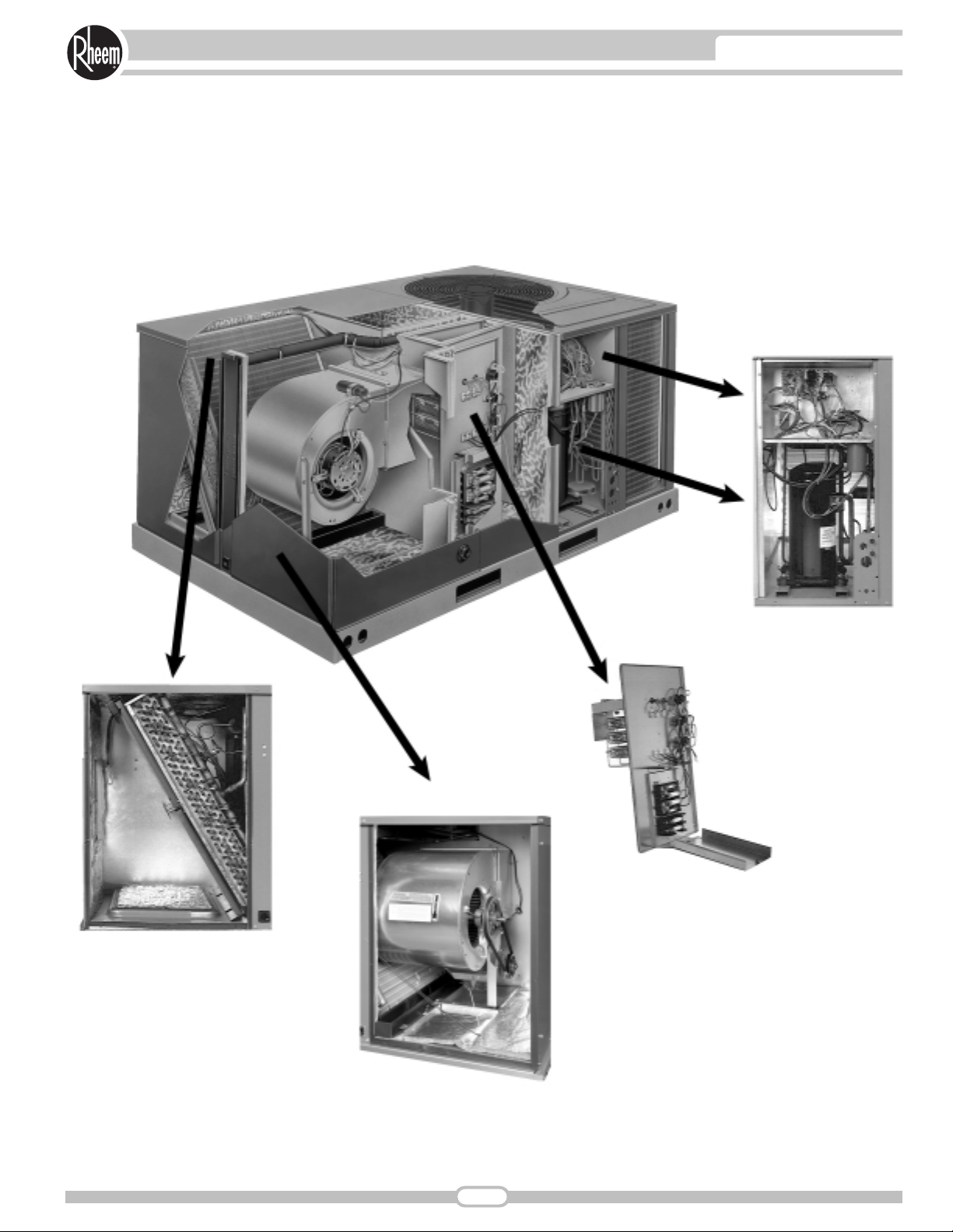
These quality features are included in the Rheem
Outdoor Package Heat Pumps
Evaporator Coil/Filter Access
Optional Electric Heater Kit
Compressor Access
Control Box Access
Blower Access
Page 4
4
INTRODUCTIONINTRODUCTION
• R-410A HFC refrigerant.
• Complete factory charged, wired and run tested.
• Scroll compressors with internal line break overload and highpressure protection.
• Single stage compressor on all models.
• Convertible airflow.
• TXV refrigerant metering system.
• High Pressure protection standard on all models. Low
Pressure/Loss of charge protection standard on all models.
• Solid Core liquid line filter drier on each circuit.
• Single slab evaporator coil facilitate easy cleaning for
maintained high efficiencies.
• Cooling operation up to 125 degree F ambient.
• Easy access to filter, blower, electric heat, and compressor/
control compartments permits prompt service.
• Powder Paint Finish meets ASTMB117 steel coated on each
side for maximum protection.
• One piece top cover and one piece base pan with drawn
supply and return opening for superior water management.
• Externally mounted refrigerant gauge ports for easy service
diagnostics.
• Easy to install plug-in; slip in, 100% fully modulating
economizer with barometric relief.
• Forkable base rails for easy handling and lifting.
• Single point electrical connection.
• High performance belt drive motor with variable pitch pulleys
and quick adjust belt system.
• Permanently lubricated evaporator and condenser motors.
• Condenser motors are internally protected, totally enclosed
with shaft down design.
• 1 inch filter standard with slide out design.
• Colored and labeled wiring.
• Copper tube/Aluminum Fin coils.
• Molded compressor plug.
• Supplemental electric heat provides 100% efficient heating.
STANDARD FEATURES INCLUDE:
These quality features are included in the
Rheem Package Heat Pump Unit
SJNL - A060, A072
Page 5
5
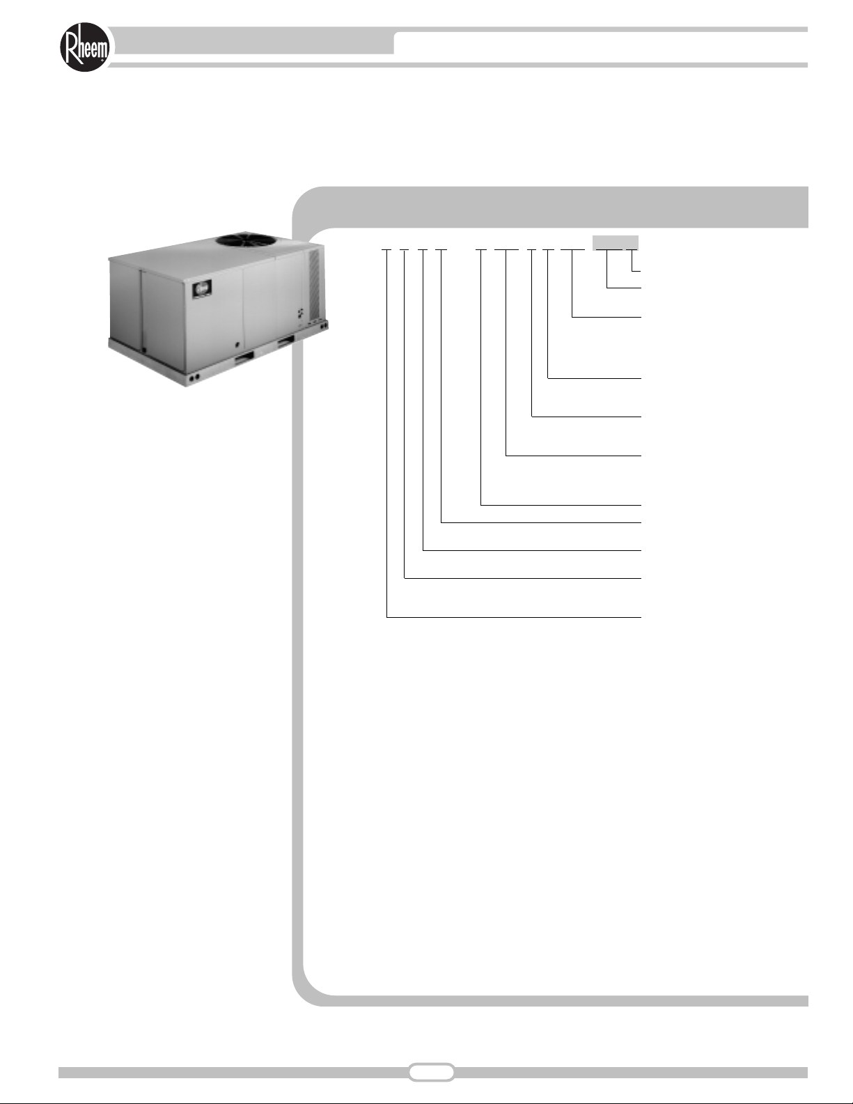
MODEL IDENTIFICATION—SJNL- SERIES
S J N L — A 060 N L 000 X X X
Economizer Option (See Next Page)
Factory Installed Options
(See Next Page)
Electric Heat
000 = No Resistance Heat
015 = 15 kW Resistance Heat
020 = 20 kW Resistance Heat
024 = 24 kW Resistance Heat
Drive Package
L = Belt Drive
M = Belt Drive
Electrical Designation
N = 380-415 V, 3 PH, 50 Hz
P = 200-220 V, 3 PH, 50 Hz
Nominal Cooling Capacity
(BTUH) [kW]
060 = 60,000 [17.58]
072 = 72,000 [21.10]
Future Technical Variations
Design Series
(R-410A)
Efficiency Designation
N = High Efficiency
Product Classification
J = Package Heat Pump—
Light Commercial
Tradebrand
S = Rheem Export
[ ] Designates Metric Conversions
Page 6
6
OPTIONS—SJNL- SERIES
FACTORY INSTALLED OPTION CODES FOR SJNL- (5-6 Ton) [17.6-21.1 kW]
Example: SJNL-A060JK000XXX (where XX
is factory installed option)
Example: No Options
SJNL-A060JK000
Example: No Options with Factory Installed Economizer
SJNL-A060JK000AAB
Example: Options with Hailguard with no Factory Installed Economizer
SJNL-A060JK000ADA
Example: Options same as above with Factory Installed Economizer
SJNL-A060JK000ADB
ECONOMIZER SELECTION FOR SJNL- (5-6 Ton) [17.6-21.1 kW]
“x” indicates factory installed option.
[ ] Designates Metric Conversions
Option Code
AD
AG x
AP x
CX x x
JC x x
Hail Guard
x
xBY
xBJ x
x
Non-Powered
Convenience Outlet
Low Ambient/
Freeze Stat
x
No Economizer
A x
B x
Single Enthalpy Economizer
With Barometric Relief
Page 7
7
GENERAL DATA—SJNL- SERIES
Model SJNL- Series A060NL A060PL A072NL
Cooling Performance
1
Gross Cooling Capacity Btu [kW] 52,500 [15.38] 52,500 [15.38] 60,000 [17.58]
EER/SEER
2
11.8/14.05 11.8/14.05 11.2/NA
Rated CFM [L/s] 1600 [755] 1600 [755] 1650 [779]
Net Cooling Capacity Btu [kW] 50,500 [14.8] 50,500 [14.8] 58,000 [16.99]
Net Sensible Capacity Btu [kW] 37,650 [11.03] 37,650 [11.03] 40,600 [11.9]
Net System Power kW 4.29 4.29 5.18
Heating Performance (Heat Pumps)
High Temp. Btuh [kW] Rating 52,000 [15.24] 52,000 [15.24] 57,500 [16.85]
System Power KW/COP 4.1/3.72 4.1/3.72 4.79/3.52
Low Temp. Btuh [kW] Rating 30,800 [9.02] 30,800 [9.02] 36,200 [10.61]
Net Weight lbs. [kg] 570 [259] 570 [259] 620 [281]
System Power KW/COP 3.67/2.46 3.67/2.46 4.28/2.48
Refrigerant Control TX Valves TX Valves TX Valves
Compressor
No./Type 1/Scroll 1/Scroll 1/Scroll
Outdoor Sound Rating (dB)
3
83 83 83
Outdoor Coil—Fin Type Louvered Louvered Louvered
Tube Type Rifled Rifled Rifled
Tube Size in. [mm] OD 0.375 [9.5] 0.375 [9.5] 0.375 [9.5]
Face Area sq. ft. [sq. m] 16.56 [1.54] 16.56 [1.54] 16.56 [1.54]
Rows / FPI [FPcm] 2 / 22 [9] 2 / 22 [9] 2 / 22 [9]
Indoor Coil—Fin Type Louvered Louvered Louvered
Tube Type Rifled Rifled Rifled
Tube Size in. [mm] 0.375 [9.5] 0.375 [9.5] 0.375 [9.5]
Face Area sq. ft. [sq. m] 5.16 [0.48] 5.16 [0.48] 6.5 [0.6]
Rows / FPI [FPcm] 4 / 13 [5] 4 / 13 [5] 4 / 13 [5]
Refrigerant Control TX Valves TX Valves TX Valves
Drain Connection No./Size in. [mm] 1/1 [25.4] 1/1 [25.4] 1/1 [25.4]
Outdoor Fan—Type Propeller Propeller Propeller
No. Used/Diameter in. [mm] 1/24 [609.6] 1/24 [609.6] 1/24 [609.6]
Drive Type/No. Speeds Direct/1 Direct/1 Direct/1
CFM [L/s] 3330 [1571] 3330 [1571] 3335 [1574]
No. Motors/HP 1 at 1/3 HP 1 at 1/3 HP 1 at 1/3 HP
Motor RPM 1075 1075 1075
Indoor Fan—Type FC Centrifugal FC Centrifugal FC Centrifugal
No. Used/Diameter in. [mm] 1/10x10 [254x254] 1/10x10 [254x254] 1/11x11 [279x279]
Drive Type/No. Speeds Belt/Variable Belt/Variable Belt/Variable
No. Motors 1 1 1
Motor HP 1 1 1 1/2
Motor RPM 1437 1437 1725
Motor Frame Size 56 56 56
Filter—Type Disposable Disposable Disposable
Furnished Yes Yes Yes
(No.) Size Recommended in. [mmxmmxmm] (2)1x25x16 [25x635x406] (2)1x25x16 [25x635x406] (4)1x16x16 [25x406x406]
Refrigerant Charge Oz. [g] 195 [5528] 195 [5528] 221 [6265]
Weights
Ship Weight lbs. [kg] 585 [265] 585 [265] 635 [288]
Net Latent Capacity Btu [kW] 12,850 [3.77] 12,850 [3.77] 17,400 [5.1]
HSPF (Btu/Watts-hr) 7.70 7.70 7.70
NOMINAL SIZES 3-5 TONS [10.6-17.6 kW]
See Page 8 for Notes.
[ ] Designates Metric Conversions
Page 8

NOTES:
1. Cooling Performance is rated at 95° F ambient, 80° F entering dry bulb, 67° F entering wet bulb. Gross capacity does
not include the effect of fan motor heat. Net capacity includes the effect of fan motor heat. Units are suitable for
operation to 20% of nominal cfm. Units are tested in accordance with the Unitary Air Conditioner Equipment
certification program, which is based on AHRI Standard 210/240 or 360.
2. EER and/or SEER are tested at AHRI conditions and in accordance with DOE test procedures.
3. Outdoor Sound Rating shown is tested in accordance with AHRI Standard 270.
8
GENERAL DATA—SJNL- SERIES
Page 9
COOLING PERFORMANCE DATA—SJNL-A060
HEATING PERFORMANCE DATA—SJNL-A060
DR —Depression ratio
dbE —Entering air dry bulb
wbE—Entering air wet bulb
Total —Total capacity x 1000 BTUH
Sens —Sensible capacity x 1000 BTUH
Power—KW input
NOTES:
➀ When the entering air dry bulb is other than 80°F [27°C], adjust the sensible
capacity from the table by adding [1.10 x CFM x (1 – DR) x (dbE – 80)].
IDB—Indoor air dry bulb [ ] Designates Metric Conversions
9
SYSTEMS PERFORMANCE—SJNL- SERIES
ENTERING INDOOR AIR @ 80°F [26.7°C] dbE ➀
3.1
3.2
3.4
3.6
3.8
4.0
4.2
4.5
4.7
5.0
60.5 [17.7]
31.2 [10.8]
3.0
59.2 [17.3]
30.7 [10.6]
3.2
57.8 [16.9]
30.2 [10.4]
3.3
56.2 [16.5]
29.6 [10.2]
3.5
54.3 [15.9]
28.7 [9.9]
3.7
52.3 [15.3]
27.7 [9.6]
3.9
50.1 [14.7]
26.7 [9.2]
4.2
47.7 [14.0]
25.4 [8.7]
4.4
45.1 [13.2]
24.0 [8.3]
4.7
42.4 [12.4]
22.7 [7.8]
4.9
60.8 [17.8]
48.7 [14.3]
3.1
59.4 [17.4]
48.0 [14.1]
3.3
57.9 [17.0]
47.3 [13.9]
3.4
56.1 [16.4]
46.2 [13.5]
3.6
54.2 [15.9]
45.3 [13.3]
3.8
52.0 [15.2]
43.8 [12.8]
4.1
49.6 [14.5]
42.3 [12.4]
4.3
47.0 [13.8]
40.7 [11.9]
4.5
44.3 [13.0]
38.9 [11.4]
4.8
41.3 [12.1]
36.8 [10.8]
5.1
O
U
T
D
O
O
R
D
R
Y
B
U
B
T
E
M
P
E
R
A
T
U
R
E
°F
[°C]
wbE 71°F [21.7°C] 67°F [19.4°C] 63°F [17.2°C]
CFM [L/s] 1920 [908] 1600 [755] 1280 [604] 1920 [908] 1600 [755] 1280 [604] 1920 [908] 1600 [755] 1280 [604]
DR ➀
Total BTUH [kW]
75
Sens BTUH [kW]
[23.9]
Power
Total BTUH [kW]
80
Sens BTUH [kW]
[26.7]
Power
Total BTUH [kW]
85
Sens BTUH [kW]
[29.4]
Power
Total BTUH [kW]
90
Sens BTUH [kW]
[32.2]
Power
Total BTUH [kW]
95
Sens BTUH [kW]
[35]
L
100
[37.8]
105
[40.6]
110
[43.3]
115
[46.1]
120
[48.9]
Power
Total BTUH [kW]
Sens BTUH [kW]
Power
Total BTUH [kW]
Sens BTUH [kW]
Power
Total BTUH [kW]
Sens BTUH [kW]
Power
Total BTUH [kW]
Sens BTUH [kW]
Power
Total BTUH [kW]
Sens BTUH [kW]
Power
.02 .07 .15 .02 .07 .15 .02 .07 .15
65.0 [19.0]
42.5 [12.5]
62.8 [18.4]
36.7 [10.8]
3.1
63.7 [18.7]
42.0 [12.3]
61.5 [18.0]
36.2 [10.6]
3.3
62.2 [18.2]
41.2 [12.1]
60.0 [17.6]
35.5 [10.4]
3.5
60.4 [17.7]
40.2 [11.8]
58.3 [17.1]
34.7 [10.2]
3.7
58.4 [17.1]
39.0 [11.4]
56.4 [16.5]
33.7 [9.9]
3.9
56.3 [16.5]
37.8 [11.1]
54.3 [15.9]
32.6 [9.6]
4.1
53.9 [15.8]
36.3 [10.6]
52.0 [15.2]
31.3 [9.2]
4.3
51.3 [15.0]
34.5 [10.1]
49.5 [14.5]
29.8 [8.7]
4.6
48.5 [14.2]
32.7 [9.6]
46.8 [13.7]
28.2 [8.3]
4.8
45.6 [13.4]
30.8 [9.0]
44.0 [12.9]
26.6 [7.8]
5.1
58.6 [17.2]
42.3 [12.4]
3.0
57.3 [16.8]
41.8 [12.2]
3.2
55.8 [16.3]
41.2 [12.1]
3.4
54.1 [15.9]
40.3 [11.8]
3.6
52.3 [15.3]
39.5 [11.6]
3.8
50.2 [14.7]
38.3 [11.2]
4.0
47.9 [14.0]
37.0 [10.8]
4.2
45.4 [13.3]
35.6 [10.4]
4.5
42.7 [12.5]
34.0 [10.0]
4.7
39.8 [11.7]
32.2 [9.4]
5.0
56.5 [16.6]
36.4 [12.4]
3.0
55.2 [16.2]
36.0 [12.2]
3.1
53.8 [15.8]
35.5 [12.1]
3.3
52.2 [15.3]
34.8 [11.8]
3.5
50.4 [14.8]
34.1 [11.6]
3.7
48.3 [14.2]
33.0 [11.2]
3.9
46.1 [13.5]
31.9 [10.8]
4.1
43.7 [12.8]
30.7 [10.4]
4.4
41.2 [12.1]
29.5 [10.0]
4.6
38.4 [11.3]
27.9 [9.4]
4.9
56.4 [16.5]
53.0 [15.5]
3.1
55.1 [16.1]
52.5 [15.4]
3.2
53.5 [15.7]
51.6 [15.1]
3.4
51.8 [15.2]
50.7 [14.9]
3.6
49.8 [14.6]
49.5 [14.5]
3.8
47.6 [13.9]
47.6 [13.9]
4.0
45.3 [13.3]
45.3 [13.3]
4.3
42.7 [12.5]
42.7 [12.5]
4.5
39.9 [11.7]
39.9 [11.7]
4.8
36.9 [10.8]
36.9 [10.8]
5.0
54.4 [15.9]
46.5 [13.6]
3.0
53.1 [15.6]
46.0 [13.5]
3.2
51.6 [15.1]
45.3 [13.3]
3.4
50.0 [14.6]
44.6 [13.1]
3.6
48.1 [14.1]
43.6 [12.8]
3.8
46.0 [13.5]
42.5 [12.5]
4.0
43.7 [12.8]
41.2 [12.1]
4.2
41.2 [12.1]
39.7 [11.6]
4.4
38.5 [11.3]
38.1 [11.2]
4.7
35.6 [10.4]
35.6 [10.4]
5.0
52.5 [15.4]
40.4 [13.6]
3.0
51.2 [15.0]
40.0 [13.5]
3.1
49.8 [14.6]
39.4 [13.3]
3.3
48.1 [14.1]
38.7 [13.1]
3.5
46.3 [13.6]
37.9 [12.8]
3.7
44.3 [13.0]
37.0 [12.5]
3.9
42.1 [12.3]
35.9 [12.1]
4.1
39.7 [11.6]
34.6 [11.6]
4.4
37.1 [10.9]
33.3 [10.9]
4.6
34.3 [10.0]
31.8 [10.0]
4.9
O
U
T
D
O
O
R
D
R
Y
B
U
B
T
E
M
P
E
R
A
T
U
R
E
°F
[°C]
L
CFM [L/s]
0
[-17.8]
5
[26.7]
10
[-12.2]
15
[32.2]
20
[-6.6]
25
[37.8]
30
[-1.1]
35
[43.3]
40
[4.4]
45
[46.1]
50
[10]
IDB
Total BTUH [kW]
Power
Total BTUH [kW]
Power
Total BTUH [kW]
Power
Total BTUH [kW]
Power
Total BTUH [kW]
Power
Total BTUH [kW]
Power
Total BTUH [kW]
Power
Total BTUH [kW]
Power
Total BTUH [kW]
Power
Total BTUH [kW]
Power
Total BTUH [kW]
Power
1920 [908] 1600 [755] 1280 [604] 1920 [908] 1600 [755] 1280 [604] 1920 [908] 1600 [755] 1280 [604]
19.1 [5.6]
2.5
22.7 [6.7]
2.6
26.2 [7.7]
2.7
29.7 [8.7]
2.7
33.2 [9.7]
2.8
36.8 [10.8]
2.9
40.3 [11.8]
2.9
43.8 [12.8]
3.0
47.3 [13.9]
3.1
50.9 [14.9]
3.1
54.4 [15.9]
3.2
60°F [15.5°C]
18.9 [5.5]
2.6
22.3 [6.5]
2.7
25.8 [7.6]
2.7
29.3 [8.6]
2.8
32.8 [9.6]
2.9
36.2 [10.6]
2.9
39.7 [11.6]
3.0
43.2 [12.7]
3.1
46.7 [13.7]
3.1
50.2 [14.7]
3.2
53.6 [15.7]
3.3
18.6 [5.4]
2.7
22.0 [6.4]
2.7
25.5 [7.5]
2.8
28.9 [8.5]
2.9
32.3 [9.5]
2.9
35.7 [10.5]
3.0
39.2 [11.5]
3.1
42.6 [12.5]
3.2
46.0 [13.5]
3.2
49.4 [14.5]
3.3
52.9 [15.5]
3.4
17.8 [5.2]
2.9
21.3 [6.2]
2.9
24.9 [7.3]
3.0
28.4 [8.3]
3.1
31.9 [9.3]
3.1
35.5 [10.4]
3.2
39.0 [11.4]
3.3
42.5 [12.5]
3.3
46.0 [13.5]
3.4
49.6 [14.5]
3.5
53.1 [15.6]
3.5
70°F [21.1°C]
17.6 [5.2]
3.0
21.0 [6.2]
3.0
24.5 [7.2]
3.1
28.0 [8.2]
3.2
31.5 [9.2]
3.2
35.0 [10.3]
3.3
38.4 [11.3]
3.4
41.9 [12.3]
3.4
45.4 [13.3]
3.5
48.9 [14.3]
3.6
52.3 [15.3]
3.6
17.3 [5.1]
3.0
20.7 [6.1]
3.1
24.2 [7.1]
3.2
27.6 [8.1]
3.2
31.0 [9.1]
3.3
34.5 [10.1]
3.4
37.9 [11.1]
3.4
41.3 [12.1]
3.5
44.7 [13.1]
3.6
48.2 [14.1]
3.6
51.6 [15.1]
3.7
16.5 [4.8]
3.3
20.0 [5.9]
3.4
23.6 [6.9]
3.4
27.1 [7.9]
3.5
30.6 [9.0]
3.6
34.1 [10.0]
3.6
37.7 [11.0]
3.7
41.2 [12.1]
3.8
44.7 [13.1]
3.8
48.2 [14.1]
3.9
51.8 [15.2]
4.0
80°F [26.7°C]
16.3 [4.8]
3.4
19.8 [5.8]
3.5
23.2 [6.8]
3.5
26.7 [7.8]
3.6
30.2 [8.8]
3.7
33.7 [9.9]
3.7
37.1 [10.9]
3.8
40.6 [11.9]
3.9
44.1 [12.9]
3.9
47.6 [13.9]
4.0
51.0 [14.9]
4.1
16.0 [4.7]
3.5
19.5 [5.7]
3.5
22.9 [6.7]
3.6
26.3 [7.7]
3.7
29.7 [8.7]
3.7
33.2 [9.7]
3.8
36.6 [10.7]
3.9
40.0 [11.7]
4.0
43.5 [12.7]
4.0
46.9 [13.7]
4.1
50.3 [14.7]
4.2
Page 10

COOLING PERFORMANCE DATA—SJNL-A072
HEATING PERFORMANCE DATA—SJNL-A072
DR —Depression ratio
dbE —Entering air dry bulb
wbE—Entering air wet bulb
Total —Total capacity x 1000 BTUH
Sens —Sensible capacity x 1000 BTUH
Power—KW input
NOTES:
➀ When the entering air dry bulb is other than 80°F [27°C], adjust the sensible
capacity from the table by adding [1.10 x CFM x (1 – DR) x (dbE – 80)].
IDB—Indoor air dry bulb [ ] Designates Metric Conversions
10
SYSTEMS PERFORMANCE—SJNL- SERIES
ENTERING INDOOR AIR @ 80°F [26.7°C] dbE ➀
3.8
4.0
4.2
4.4
4.6
4.8
5.1
5.3
5.5
5.8
69.1 [20.2]
33.0 [11.5]
3.7
67.4 [19.7]
32.3 [11.2]
3.9
65.8 [19.3]
31.6 [10.9]
4.1
64.3 [18.8]
31.1 [10.8]
4.3
62.9 [18.4]
30.6 [10.6]
4.5
61.7 [18.1]
30.2 [10.4]
4.7
60.6 [17.8]
29.9 [10.3]
5.0
59.6 [17.5]
29.6 [10.3]
5.2
58.8 [17.2]
29.6 [10.2]
5.4
58.1 [17.0]
29.5 [10.2]
5.7
68.9 [20.2]
52.5 [15.4]
3.8
67.0 [19.6]
51.4 [15.1]
4.0
65.3 [19.1]
50.5 [14.8]
4.2
63.7 [18.7]
49.7 [14.6]
4.4
62.2 [18.2]
49.0 [14.4]
4.7
60.9 [17.8]
48.4 [14.2]
4.9
59.7 [17.5]
47.9 [14.0]
5.1
58.7 [17.2]
47.6 [13.9]
5.3
57.8 [16.9]
47.3 [13.9]
5.6
57.1 [16.7]
47.3 [13.9]
5.8
O
U
T
D
O
O
R
D
R
Y
B
U
B
T
E
M
P
E
R
A
T
U
R
E
°F
[°C]
wbE 71°F [21.7°C] 67°F [19.4°C] 63°F [17.2°C]
CFM [L/s] 1980 [935] 1650 [779] 1320 [623] 1980 [935] 1650 [779] 1320 [623] 1980 [935] 1650 [779] 1320 [623]
DR ➀
Total BTUH [kW]
75
Sens BTUH [kW]
[23.9]
Power
Total BTUH [kW]
80
Sens BTUH [kW]
[26.7]
Power
Total BTUH [kW]
85
Sens BTUH [kW]
[29.4]
Power
Total BTUH [kW]
90
Sens BTUH [kW]
[32.2]
Power
Total BTUH [kW]
95
Sens BTUH [kW]
[35]
L
100
[37.8]
105
[40.6]
110
[43.3]
115
[46.1]
120
[48.9]
Power
Total BTUH [kW]
Sens BTUH [kW]
Power
Total BTUH [kW]
Sens BTUH [kW]
Power
Total BTUH [kW]
Sens BTUH [kW]
Power
Total BTUH [kW]
Sens BTUH [kW]
Power
Total BTUH [kW]
Sens BTUH [kW]
Power
.02 .07 .15 .02 .07 .15 .02 .07 .15
74.4 [21.8]
45.6 [13.4]
71.8 [21.0]
39.1 [11.5]
3.9
72.5 [21.2]
44.5 [13.0]
69.9 [20.5]
38.1 [11.2]
4.1
70.7 [20.7]
43.5 [12.7]
68.2 [20.0]
37.3 [10.9]
4.3
69.1 [20.2]
42.7 [12.5]
66.7 [19.5]
36.7 [10.8]
4.5
67.7 [19.8]
42.1 [12.3]
65.3 [19.1]
36.1 [10.6]
4.7
66.3 [19.4]
41.4 [12.1]
64.0 [18.8]
35.6 [10.4]
4.9
65.2 [19.1]
41.1 [12.0]
62.9 [18.4]
35.3 [10.3]
5.1
64.1 [18.8]
40.7 [11.9]
61.9 [18.1]
35.0 [10.3]
5.4
63.3 [18.5]
40.6 [11.9]
61.0 [17.9]
34.8 [10.2]
5.6
62.5 [18.3]
40.3 [11.8]
60.3 [17.7]
34.7 [10.2]
5.9
66.5 [19.5]
45.6 [13.4]
3.8
64.7 [19.0]
44.7 [13.1]
4.0
63.0 [18.5]
43.9 [12.9]
4.2
61.5 [18.0]
43.3 [12.7]
4.4
60.1 [17.6]
42.7 [12.5]
4.6
58.8 [17.2]
42.2 [12.4]
4.8
57.7 [16.9]
41.8 [12.2]
5.0
56.7 [16.6]
41.5 [12.2]
5.2
55.8 [16.3]
41.3 [12.1]
5.5
55.1 [16.1]
41.3 [12.1]
5.7
64.1 [18.8]
39.2 [13.4]
3.7
62.3 [18.3]
38.4 [13.1]
3.9
60.7 [17.8]
37.7 [12.9]
4.1
59.2 [17.3]
37.2 [12.7]
4.3
57.9 [17.0]
36.7 [12.5]
4.5
56.6 [16.6]
36.3 [12.4]
4.7
55.6 [16.3]
36.0 [12.2]
4.9
54.6 [16.0]
35.7 [12.2]
5.2
53.8 [15.8]
35.6 [12.1]
5.4
53.1 [15.6]
35.6 [12.1]
5.6
66.2 [19.4]
61.1 [17.9]
3.8
64.3 [18.8]
60.1 [17.6]
4.0
62.5 [18.3]
59.1 [17.3]
4.2
60.9 [17.8]
58.3 [17.1]
4.4
59.5 [17.4]
57.7 [16.9]
4.6
58.1 [17.0]
57.0 [16.7]
4.8
57.0 [16.7]
56.6 [16.6]
5.1
55.9 [16.4]
55.9 [16.4]
5.3
55.1 [16.1]
55.1 [16.1]
5.5
54.3 [15.9]
54.3 [15.9]
5.8
63.8 [18.7]
53.5 [15.7]
3.7
62.0 [18.2]
52.7 [15.4]
3.9
60.3 [17.7]
51.9 [15.2]
4.1
58.8 [17.2]
51.2 [15.0]
4.3
57.4 [16.8]
50.7 [14.9]
4.5
56.1 [16.4]
50.1 [14.7]
4.8
55.0 [16.1]
49.8 [14.6]
5.0
54.0 [15.8]
49.5 [14.5]
5.2
53.1 [15.6]
49.3 [14.4]
5.4
52.4 [15.4]
49.2 [14.4]
5.7
61.5 [18.0]
46.4 [15.7]
3.7
59.8 [17.5]
45.8 [15.4]
3.9
58.1 [17.0]
45.1 [15.2]
4.1
56.6 [16.6]
44.4 [15.0]
4.3
55.3 [16.2]
44.1 [14.9]
4.5
54.1 [15.9]
43.6 [14.7]
4.7
53.0 [15.5]
43.3 [14.6]
4.9
52.0 [15.2]
43.1 [14.5]
5.1
51.2 [15.0]
43.0 [14.4]
5.4
50.5 [14.8]
42.9 [14.4]
5.6
O
U
T
D
O
O
R
D
R
Y
B
U
B
T
E
M
P
E
R
A
T
U
R
E
°F
[°C]
L
CFM [L/s]
0
[-17.8]
5
[26.7]
10
[-12.2]
15
[32.2]
20
[-6.6]
25
[37.8]
30
[-1.1]
35
[43.3]
40
[4.4]
45
[46.1]
50
[10]
IDB
Total BTUH [kW]
Power
Total BTUH [kW]
Power
Total BTUH [kW]
Power
Total BTUH [kW]
Power
Total BTUH [kW]
Power
Total BTUH [kW]
Power
Total BTUH [kW]
Power
Total BTUH [kW]
Power
Total BTUH [kW]
Power
Total BTUH [kW]
Power
Total BTUH [kW]
Power
1980 [935] 1650 [779] 1320 [623] 1980 [935] 1650 [779] 1320 [623] 1980 [935] 1650 [779] 1320 [623]
23.7 [6.9]
2.9
27.3 [8.0]
3.0
30.9 [9.1]
3.1
34.5 [10.1]
3.1
38.2 [11.2]
3.2
41.8 [12.2]
3.3
45.4 [13.3]
3.4
49.1 [14.4]
3.5
52.7 [15.4]
3.6
56.3 [16.5]
3.7
59.9 [17.6]
3.7
60°F [15.5°C]
23.3 [6.8]
3.0
26.9 [7.9]
3.1
30.5 [8.9]
3.1
34.1 [10.0]
3.2
37.6 [11.0]
3.3
41.2 [12.1]
3.4
44.8 [13.1]
3.5
48.4 [14.2]
3.6
51.9 [15.2]
3.7
55.5 [16.3]
3.7
59.1 [17.3]
3.8
23.0 [6.7]
3.0
26.5 [7.8]
3.1
30.0 [8.8]
3.2
33.6 [9.8]
3.3
37.1 [10.9]
3.4
40.6 [11.9]
3.5
44.2 [13.0]
3.6
47.7 [14.0]
3.7
51.2 [15.0]
3.7
54.7 [16.0]
3.8
58.3 [17.1]
3.9
22.1 [6.5]
3.3
25.7 [7.5]
3.4
29.4 [8.6]
3.5
33.0 [9.7]
3.5
36.6 [10.7]
3.6
40.3 [11.8]
3.7
43.9 [12.9]
3.8
47.5 [13.9]
3.9
51.2 [15.0]
4.0
54.8 [16.1]
4.0
58.4 [17.1]
4.1
70°F [21.1°C]
21.8 [6.4]
3.4
25.4 [7.4]
3.5
29.0 [8.5]
3.6
32.5 [9.5]
3.6
36.1 [10.6]
3.7
39.7 [11.6]
3.8
43.3 [12.7]
3.9
46.9 [13.7]
4.0
50.4 [14.8]
4.1
54.0 [15.8]
4.2
57.6 [16.9]
4.2
21.5 [6.3]
3.5
25.0 [7.3]
3.6
28.6 [8.4]
3.6
32.1 [9.4]
3.7
35.6 [10.4]
3.8
39.1 [11.5]
3.9
42.7 [12.5]
4.0
46.2 [13.5]
4.1
49.7 [14.6]
4.2
53.2 [15.6]
4.3
56.8 [16.6]
4.3
20.6 [6.0]
3.7
24.2 [7.1]
3.8
27.8 [8.1]
3.9
31.5 [9.2]
4.0
35.1 [10.3]
4.1
38.7 [11.3]
4.2
42.4 [12.4]
4.2
46.0 [13.5]
4.3
49.6 [14.5]
4.4
53.3 [15.6]
4.5
56.9 [16.7]
4.6
80°F [26.7°C]
20.3 [5.9]
3.8
23.9 [7.0]
3.9
27.5 [8.1]
4.0
31.0 [9.1]
4.1
34.6 [10.1]
4.2
38.2 [11.2]
4.3
41.8 [12.2]
4.4
45.3 [13.3]
4.4
48.9 [14.3]
4.5
52.5 [15.4]
4.6
56.1 [16.4]
4.7
20.0 [5.9]
3.9
23.5 [6.9]
4.0
27.1 [7.9]
4.1
30.6 [9.0]
4.2
34.1 [10.0]
4.3
37.6 [11.0]
4.4
41.2 [12.1]
4.5
44.7 [13.1]
4.5
48.2 [14.1]
4.6
51.8 [15.2]
4.7
55.3 [16.2]
4.8
Page 11
AIRFLOW PERFORMANCE — 5 TON [17.6 kW]
COMPONENT AIR RESISTANCE — 5 TON [17.6 kW]
NOTES: 1. Factory sheave settings are shown in bold type.
2. Do not set motor sheave below minimum turns open shown.
3. Re-adjustment of sheave required to achieve rated airflow at AHRI minimum External Static Pressure
4. Drive data shown is for horizontal airflow with dry coil. Add component resistance (below) to duct resistance to determine total External Static Pressure.
AIRFLOW CORRECTION FACTORS — 5 TON [17.6 kW]
NOTE: Multiply correction factor times gross performance data — resulting sensible capacity cannot exceed total capacity.
[ ] Designates Metric Conversions
0.98 0.99TOTAL MBH 0.97
0.99
0.98
0.97
1700
[802]
1.00 1.00
1.000.99
1.02
1900
[897]
POWER kW 0.98 1.000.99
0.99
1800
[849]
0.94SENSIBLE MBH 0.90 0.92
1600
[755]
CFM
[L/s]
1400
[661]
1500
[708]
1.00
1.00
1.02
2000
[944]
1.10
1.01
1.03
2100
[991]
11
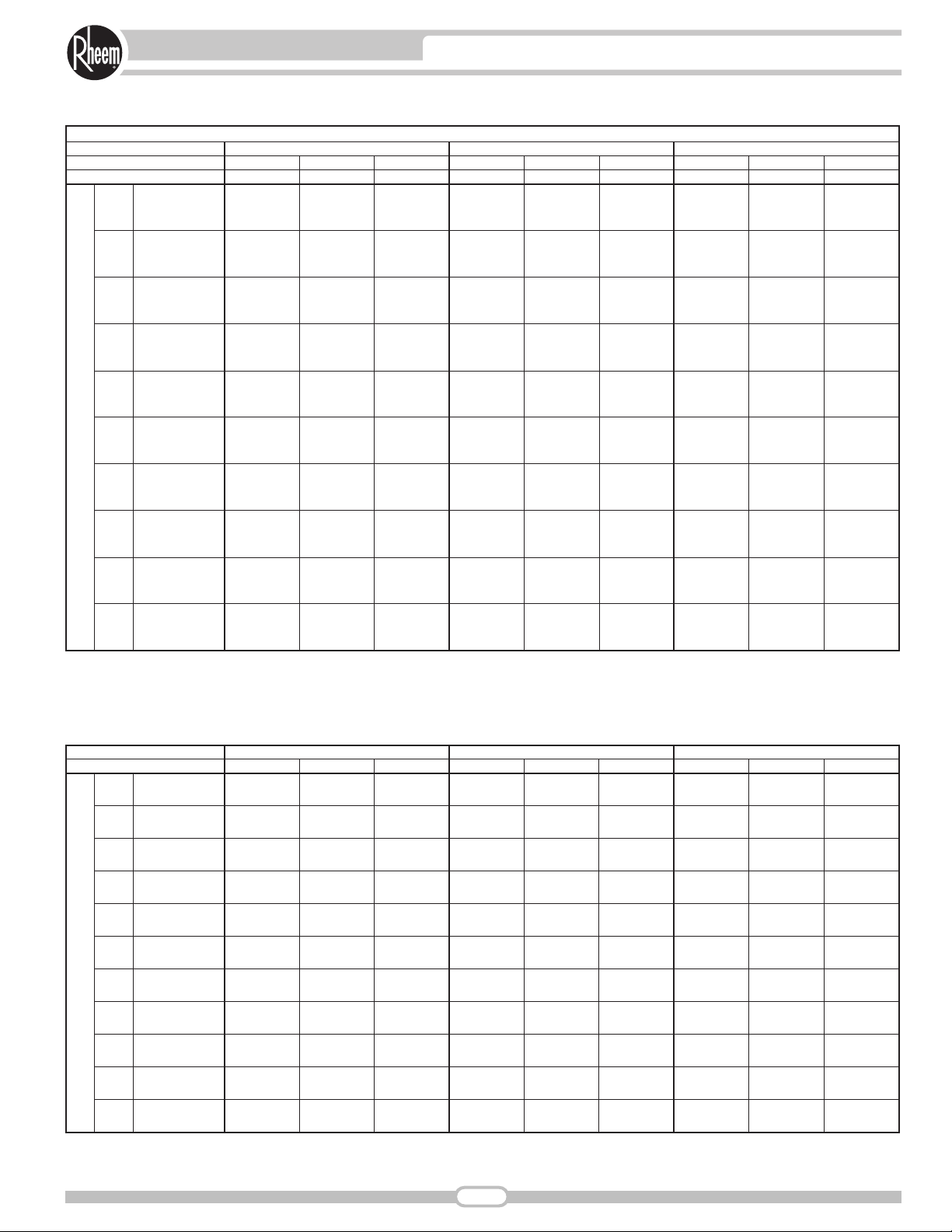
AIRFLOW PERFORMANCE—SJNL- SERIES
External Static Pressure—Inches of Water [kPa]
Model SJNL-A060
Voltage 200-220, 380-415, 50Hz—3 Phase
Air Flow
CFM [L/s]
0.1 [.02] 0.2 [.05] 0.3 [.07] 0.4 [.10] 0.5 [.12] 0.6 [.15] 0.7 [.17] 0.8 [.20] 0.9 [.22] 1.0 [.25] 1.1 [.27]
RPM W RPM W RPM W RPM W RPM W RPM W RPM W RPM W RPM W RPM W RPM W
1400 [661] — — — — — — — — — — 930 460 970 490 1030 540 1065 570 1105 595 1150 615
1500 [708] — — — — — — — — — — 945 500 995 540 1045 595 1080 615 1135 650 1165 685
1600 [755] — — — — — — — — 915 510 965 560 1015 600 1060 640 1105 680 1145 705 1180 730
Resistance—Inches Water [kPa]
930
0.060 0.065 0.070 0.078 0.085 0.093 0.100 0.107
1400 [661] 1500 [708] 1600 [755] 1700 [802] 1800 [849] 1900 [897] 2000 [944] 2100 [991]
CFM [L/s]
RPM 1170 1133 1087 1041 995 954 912
Turns Open 0 1 2 3 4 5 6
Motor Sheave 1VP-50
Drive Package L
Blower Sheave AK66
1700 [802] — — — — — — — — 940 570 990 605 1035 640 1075 680 1120 725 1160 755 — —
1800 [849] — — — — — — 915 540 965 675 1010 660 1055 710 1100 760 1140 785 1175 810 — —
1900 [897] — — — — — — 945 640 995 675 1035 720 1070 775 1120 810 1160 850 — — — —
2000 [944] — — — — 655 970 700 1015 730 1055 790 1105 830 1145 875 1180 910 — — — —
2100 [991] — — 915 655 955 705 1005 760 1040 820 1090 870 1130 910 1170 950 — — — — — —
Motor H.P. [W] 1.5 [118.5]
Wet Coil
0.066 0.069 0.072 0.076 0.080 0.083 0.086 0.089
[0.015] [0.016] [0.017] [0.019] [0.021] [0.023] [0.025] [0.027]
0.066 0.069 0.072 0.076 0.080 0.083 0.086 0.092
[0.016] [0.017] [0.018] [0.019] [0.020] [0.021] [0.021] [0.022]
Downflow Economizer RA Damper Open
Downflow
0.02 0.03 0.04 0.05 0.06 0.07 0.08 0.09
0.066 0.069 0.072 0.076 0.080 0.083 0.086 0.092
[0.016] [0.017] [0.018] [0.019] [0.000] [0.021] [0.021] [0.023]
[0.016] [0.017] [0.018] [0.019] [0.000] [0.021] [0.021] [0.023]
[0.005] [0.007] [0.010] [0.012] [0.015] [0.017] [0.020] [0.022]
Concentric Grill RXRN-FA65 or
RXRN-FA75 & Transition RXMC-CC04
Horizontal Economizer RA Damper Open
Page 12

NOTES: 1. Factory sheave settings are shown in bold type.
2. Do not set motor sheave below minimum or maximum turns open shown.
3. Re-adjustment of sheave required to achieve rated airflow at AHRI minimum External Static Pressure
4. Drive data shown is for horizontal airflow with dry coil. Add component resistance (below) to duct resistance to determine total External Static Pressure.
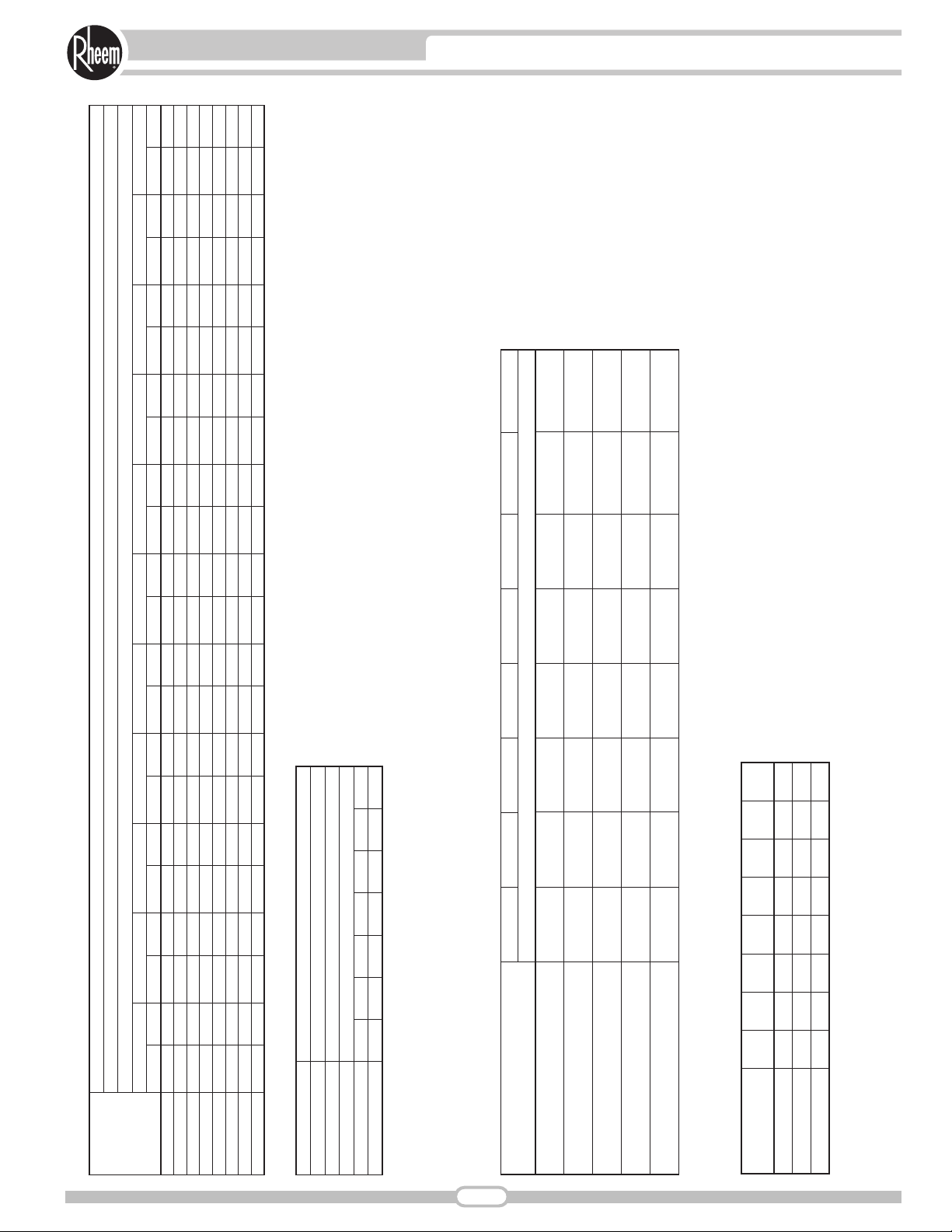
BELT-DRIVE AIRFLOW PERFORMANCE — 6 TON [21.1 kW]
NOTE: L – drive left of bold line, M – drive right of bold line.
COMPONENT AIR RESISTANCE — 6 TON [21.1 kW]
AIRFLOW CORRECTION FACTORS — 6 TON [21.1 kW]
NOTE: Multiply correction factor times gross performance data — resulting sensible capacity cannot exceed total capacity.
[ ] Designates Metric Conversions
0.98 0.98TOTAL MBH 0.97
0.99
0.97
0.94
1600
[755]
0.99 1.00
1.000.99
0.99
1800
[849]
POWER kW 0.98 0.990.98
0.97
1700
[802]
0.92SENSIBLE MBH 0.87 0.90
1500
[708]
CFM
[L/s]
1300
[613]
1400
[661]
1.00
1.00
1.02
1900
[897]
1.00
1.00
1.02
2000
[944]
12
AIRFLOW PERFORMANCE—SJNL- SERIES
Models SJNL-A072
Voltage 380/415, 50 Hz—3 Phase
Air Flow
External Static Pressure—Inches of Water [kPa]
0.1 [.02] 0.2 [.05] 0.3 [.07] 0.4 [.10] 0.5 [.12] 0.6 [.15] 0.7 [.17] 0.8 [.20] 0.9 [.22] 1.0 [.25] 1.1 [.27] 1.2 [.30] 1.3 [.32] 1.4 [.35]
RPM W RPM W RPM W RPM W RPM W RPM W RPM W RPM W RPM W RPM W RPM W RPM W RPM W RPM W
CFM [L/s]
Resistance—Inches Water [kPa]
0.03 0.03 0.03 0.04 0.04 0.05 0.05 0.06
[.01] [.01] [.01] [.01] [.01] [.01] [.01] [.01]
0.02 0.03 0.03 0.03 0.04 0.04 0.04 0.04
[.00] [.01] [.01] [.01] [.01] [.01] [.01] [.01]
0.05 0.06 0.06 0.06 0.07 0.07 0.08 0.08
[.01] [.01] [.01] [.01] [.02] [.02] [.02] [.02]
0.05 0.06 0.06 0.06 0.07 0.07 0.08 0.08
[.01] [.01] [.01] [.01] [.02] [.02] [.02] [.02]
0.01 0.01 0.02 0.02 0.03 0.04 0.07 0.08
[.00] [.00] [.00] [.00] [.01] [.01] [.02] [.02]
1300 [613] 1400 [661] 1500 [708] 1600 [755] 1700 [802] 1800 [849] 1900 [897] 2000 [944]
829
CFM [L/s]
RPM 919 877 834 792 749 707 1151 1104 1059 1014 969 924
Turns Open 0 1 2 3 4 5 0 1 2 3 4 5
Motor Sheave 1VP-44 1VP-50
1300 [613] — — — — — — 738 359 787 381 836 406 883 435 930 466 977 500 1023 538 1068 578 1113 621 1157 668 — —
1400 [661] — — — — 708 355 757 377 804 403 851 431 897 463 943 498 988 535 1033 576 1077 619 1120 666 1163 716 — —
1500 [708] — — — — 730 378 776 404 822 433 868 465 913 499 957 537 1001 578 1044 622 1087 669 1129 719 1170 772 — —
1600 [755] — — 706 383 752 409 798 438 842 471 886 506 930 544 973 585 1015 630 1057 677 1098 727 1139 780 — — — —
1700 [802] — — 732 419 776 449 820 481 864 517 906 555 949 597 990 641 1031 689 1071 740 1111 793 1150 850 — — — —
1800 [849] 715 434 759 464 802 497 845 533 887 571 928 613 969 658 1009 706 1048 757 1087 810 1126 867 1163 927 — — — —
1900 [897] 745 484 787 517 553 870 592 911 634 951 679 990 727 1029 778 1067 833 1105 890 1142 950 — — — — — —
2000 [944] 777 541 818 578 858 617 898 659 937 705 975 753 1013 805 1051 859 1087 917 1124 977 1159 1040 — — — — — —
Drive Package L M
Blower Sheave AK66 AK59
Motor H.P. [W] 1.5 [1118.5] 1.5 [1118.5]
Wet Coil
Downflow Economizer RA Damper Open
Downflow
Concentric Grill RXRN-FA65 or
RXRN-FA75 & Transition RXMC-CC04
Horizontal Economizer RA Damper Open
Page 13

13
ELECTRICAL DATA—SJNL- SERIES
ELECTRICAL DATA – SJNL SERIES
1. Horsepower Per Compressor.
2. Amp Draw Per Motor. Multiply Value By Number of Motors to Determine Total Amps.
Unit Operating
Voltage Range
Volts 380/415
Minimum Circuit Ampacity 14/14 26/26
Minimum Overcurrent
Unit Information
Compressor Motor
Condenser Motor
Evaporator Fan
Protection Device Size
Maximum Overcurrent
Protection Device Size
No.
Volts 380/415
Phase 3
RPM 2874
HP, Compressor 1 5 5
Amps (RLA), Comp. 1 7.8/7.8
Amps (LRA), Comp. 1
No.
Volts 380/415
Phase 1
HP 1/3
Amps (FLA, each) 1/1
Amps (LRA, each)
No.
Volts 380/415
Phase 3
HP 1
Amps (FLA, each) 1.9/1.9
Amps (LRA, each) 12/12 24/24
A060NL A060PL
342-457
20/20
20/20
1
52/52
1
2.4/2.4
1
180-242
200/220
30/30
40/40
1
200/220
3
2874
16/16
110/110
1
200/220
1
1/3
2.2/2.2
4.7/4.7
1
200/220
3
1
3.8/3.8
A072NL
342-457
380/415
16/16
20/20
25/25
1
380/415
3
2874
7 1/2
9.7/9.7
64/64
1
380/415
1
1/3
1/1
2.2/2.2
1
380/415
3
1 1/2
2.8/2.8
17/17
Page 14

+ Field Installed Only
* = For Canadian Use Only. Uses “P” Fuses for Inductive Circuit.
14
UNITS WITH HEATER KITS—SJNL- SERIES
+ Field Installed Only
* = For Canadian Use Only. Uses “P” Fuses for Inductive Circuit.
@ 220 V
Min./Max.
Protective Device Size
@ 200 V
Heat Pump Over Current
Min./Max.
Min. Ckt.
Ampacity
200-220 V
Heat Pump
Size
Heater Kit
Max. Fuse
— — 26/26 30/40 30/40
25/27 25/30 — — —
15/16 15/20 — — —
Min. Ckt.
Ampacity
Heater Kit
@ 220 V
Min./Max.
Over Current
Protective Device Size
@ 200 V
Min./Max.
29/31 30/35 — — —
@ 415 V
Min./Max.
Protective Device Size
@ 380 V
Heat Pump Over Current
Min./Max.
Min. Ckt.
Ampacity
380-415 V
Heat Pump
Size
Heater Kit
Max. Fuse
— — 14/14 20/20 20/20
37/40 40/40 — — —
49/54 50/60 — — —
Min. Ckt.
Heater Kit
Over Current
Protective Device Size
Ampacity
@ 415 V
Min./Max.
@ 380 V
Min./Max.
7/8 15/15 — — —
12/13 15/15 — — —
— — 16/16 20/25 20/25
18/19 20/20 — — —
24/26 25/30 — — —
18/19 20/20 — — —
24/26 25/30 — — —
14/15 15/15 — — —
29/32 30/35 — — —
Ampacity
@ 200-220 V
Unit Min. Ckt.
Amp.
Heater
@ 200-220 V
Heater
KBTU/Hr
@ 200-220 V
Heater kW
@ 200-220 V
—
3.9/4.7
6.7/8.1
7.8/9.4
10/12.1
13.3/16.2
Rated
Single Power Supply For Both Unit and Heater Kit Separate Power Supply For Both Unit and Heater Kit
Steps
No. of
Sequence
200-220 VOLT, THREE PHASE, 50 HZ, AUXILIARY ELECTRIC HEATER KITS CHARACTERISTICS AND APPLICATION
A10C 1 22.73/27.53 19.2/21.2 51/53 60/60 60/60
A15C 1 34.2/41.35 28.9/31.8 63/66 70/70 70/70
RXJJ-
Heater Kit
A06C 1 13.3/16.09 11.2/12.4 41/42 45/50 45/50
No Heat — — — 26/26 30/40 30/40
Nominal kW
A12C 1 26.59/32.17 22.5/24.8 55/57 60/60 60/60
A20C 1 45.45/55.17 38.5/42.4 75/80 80/80 90/90
Ampacity
@ 380-415 V
Unit Min. Ckt.
Amp.
Heater
@ 380-415 V
Heater
KBTU/Hr
@ 380-415 V
Rated
Heater kW
—
3.5/4.2
@ 380-415 V
6/7.2
7/8.4
9.1/10.8
12.1/14.5
—
9.1/10.8
12.1/14.5
15.1/18
Single Power Supply For Both Unit and Heater Kit Separate Power Supply For Both Unit and Heater Kit
Steps
No. of
Sequence
380-415 VOLT, THREE PHASE, 50 HZ, AUXILIARY ELECTRIC HEATER KITS CHARACTERISTICS AND APPLICATION
A10D 1 20.62/24.59 9.2/10 26/27 25/25 30/30
A15D 1 30.93/36.89 13.8/15 32/33 35/35 35/35
A20D 1 41.42/49.4 18.4/20.1 38/40 40/40 40/40
RXJJ-
Heater Kit
A06D 1 11.91/14.2 5.3/5.8 21/22 25/25 25/25
No Heat — — — 14/14 20/20 20/20
Nominal kW
A12D 1 24/28.62 10.7/11.7 28/29 30/30 30/30
A15D 1 30.93/36.89 13.8/15 34/35 35/35 40/40
No Heat — — — 16/16 20/25 20/25
A20D 1 41.42/49.4 18.4/20.1 40/42 40/40 45/45
A24D 1 51.37/61.27 22.9/25 45/48 50/50 50/50
No.
Model
SJNL-
A060PL
No.
Model
SJNL-
A060NL
A072NL
Page 15

SELECTION PROCEDURE
1. Determine cooling and heating requirements at design
conditions.
Example:
Total cooling capacity ..............56,600 BTUH [16.59 kW]
Sensible cooling capacity........34,000 BTUH [9.96 kW]
Condenser entering air............95°F [35°C]
Evaporator entering air............67°F [19°C] wb/76°F [24°C] db
Indoor air flow..........................1650 CFM [779 L/s]
External static pressure ..........0.6 in wg
2. Select unit to meet cooling requirements.
Since total cooling is within the range of 6 ton [21.10 kW] unit,
enter cooling performance table, at 95°F [35°C] outdoor temperature, 67°F [19°C] wb entering indoor air, and 1650 CFM [779 L/s]:
Total capacity ..........................60,100 BTUH [17.6 kW]
Power input..............................4.6 kW
And also, at 76°F [24°C] db indoor entering air, and using the
formula at the bottom of the page:
Sensible capacity ....................35,948 BTUH [10.53 kW]
3. Determine blower speed and power to meet the system
requirements.
At the given external static pressure of 0.6 in wg, the belt model
must be selected. Enter the belt drive blower performance table at
1650 CFM [779 L/s] and 0.6 in wg ESP:
RPM....................896
Watts ..................531
Drive....................L
4. Calculate indoor blower BTUH heat effect.
BTUH = Watts x 3.413 = 1812
5. Calculate net cooling capacities.
Net total cooling = 60,100 – 1812 = 58,288 BTUH [17.08 kW]
Net sensible cooling = 35,948 – 1812 = 34,136 BTUH [10.00 kW]
[ ] Designates Metric Conversions
15
SELECTION PROCEDURE—SJNL- SERIES
Page 16

16
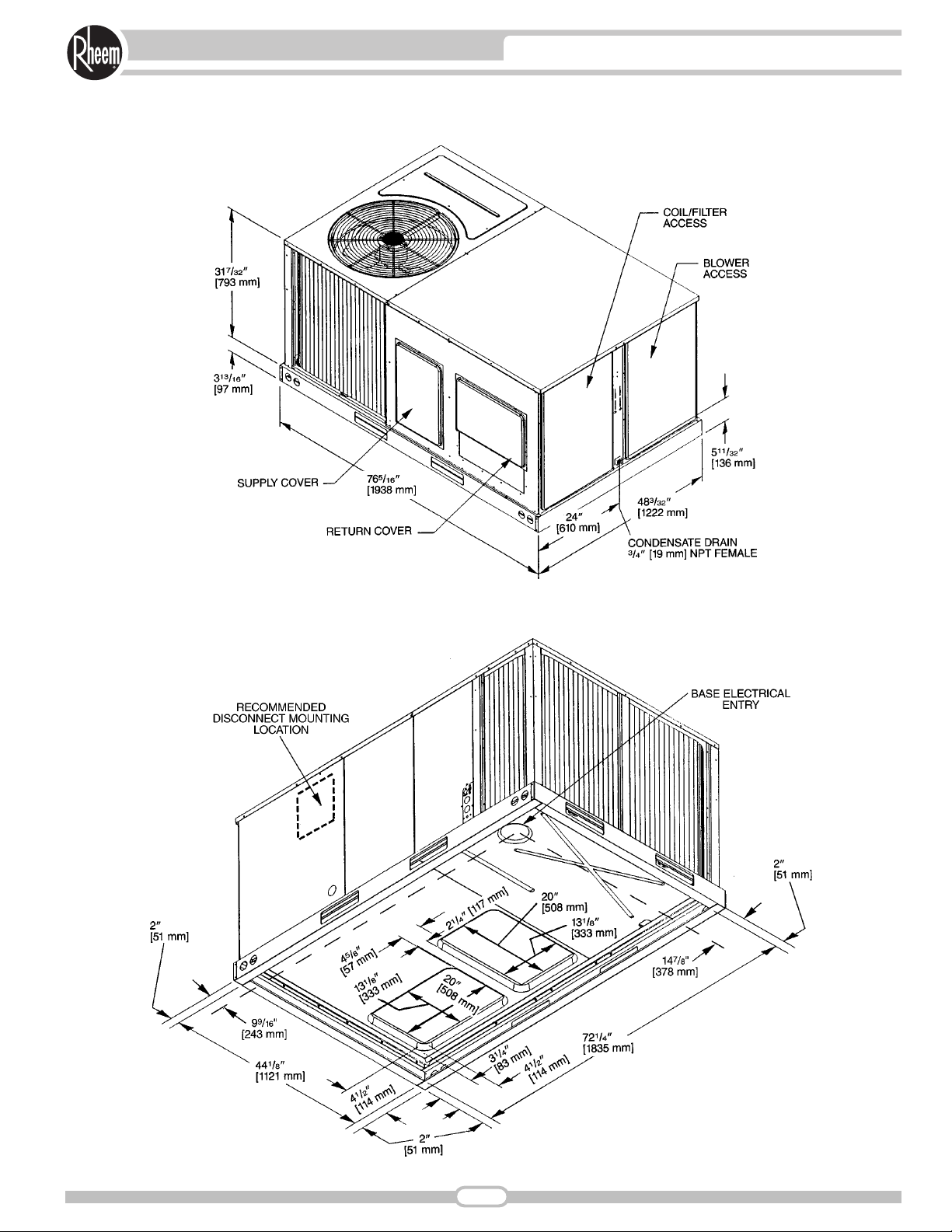
UNIT DIMENSIONS—SJNL- SERIES
UNIT DIMENSIONS
PACKAGE HEAT PUMPS
5 TON [17.6 kW]
[ ] Designates Metric Conversions
Page 17
17
UNIT DIMENSIONS—SJNL- SERIES
UNIT DIMENSIONS
PACKAGE HEAT PUMPS
5 TON [17.6 kW]
[ ] Designates Metric Conversions
BOTTOM VIEW
Page 18
18
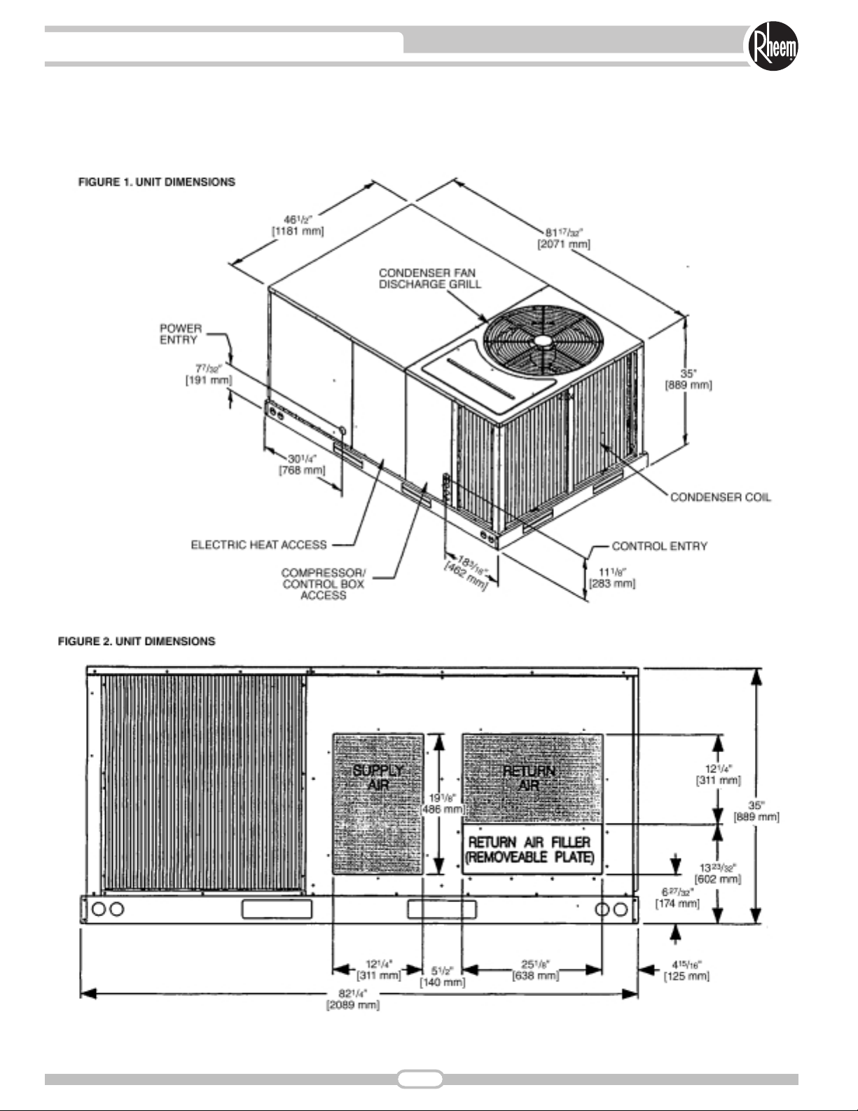
UNIT DIMENSIONS—SJNL- SERIES
[ ] Designates Metric Conversions
UNIT DIMENSIONS
PACKAGE HEAT PUMPS
6 TON [21.1 kW]
Page 19

19
UNIT DIMENSIONS—SJNL- SERIES
[ ] Designates Metric Conversions
UNIT DIMENSIONS
PACKAGE HEAT PUMPS
6 TON [21.1 kW]
Page 20

WEIGHTS
CENTER OF GRAVITY (C.G.)
CLEARANCES
(5 to 6 Ton [17.6 to 21.1 kW] Models)
The following minimum clearances are recommended
for proper unit performance and serviceability.
NOTE: Supply duct may
be installed with “0” inch
clearance to combustible
materials, provided 1"
[25.4 mm] minimum.
Fiberglass insulation is
applied either inside or on
the outside of the duct.
CLEARANCES
5 to 6 Ton
[17.6 to 21.1 kW] Models
[ ] Designates Metric Conversions
20
UNIT DIMENSIONS—SJNL- SERIES
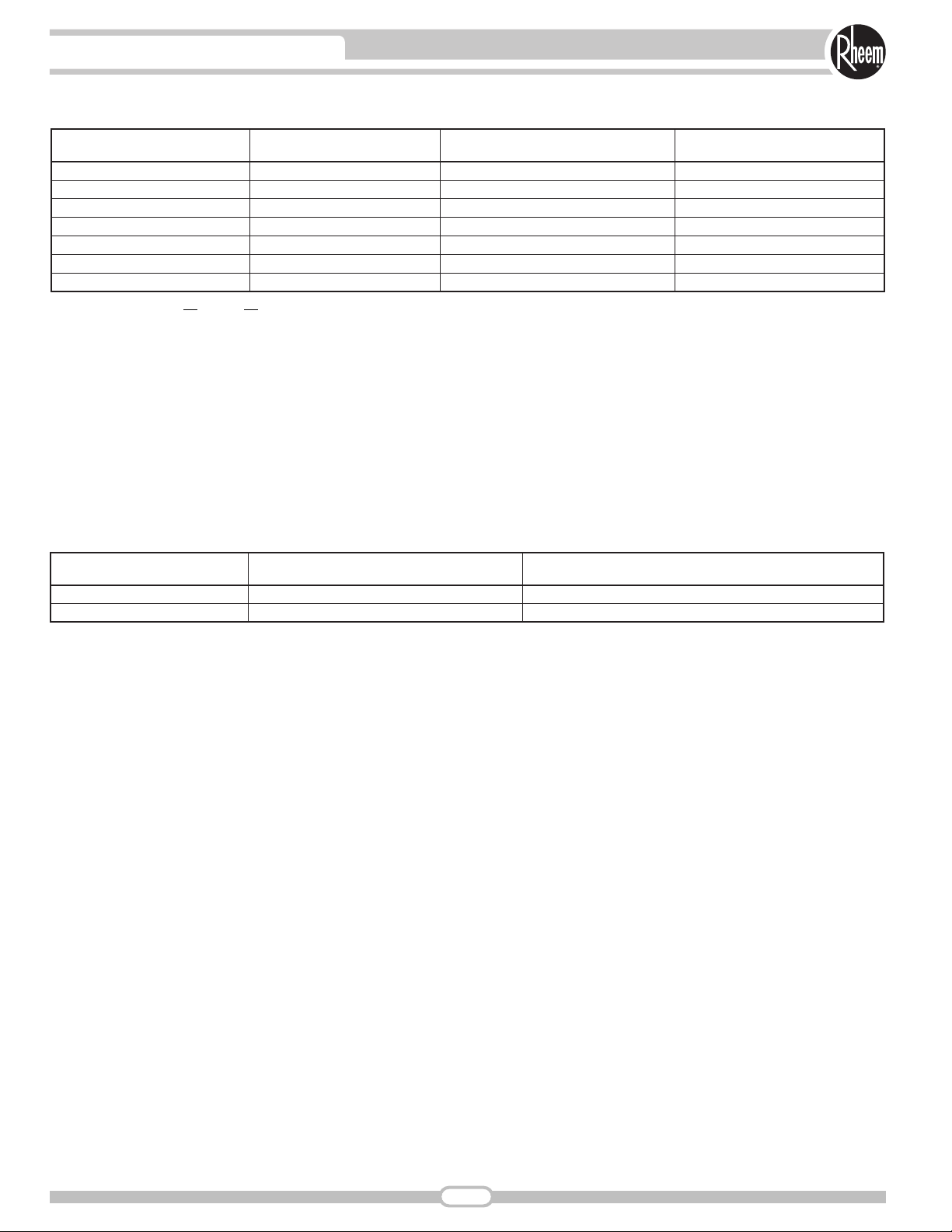
5 Ton [17.6 kW]
Accessory
Economizer with Single Enthalpy 70 [32]
Fresh Air Damper (Manual) 11 [5] 9 [4]
Fresh Air Damper (Motorized) 13 [6]
Roof Curb 14" 92 [42] 88 [40]
Roof Curb 24" 108 [49] 104 [47]
Concentric Diffuser 18" Flush 37 [17] 26 [12]
Concentric Diffuser 20" Flush 54 [24] 42 [19]
Side Discharge Concentric Diffuser RXRN-FA60 35 [16] 20 [9]
Side Discharge Concentric Diffuser RXRN-FA65 55 [25] 40 [18]
Recommended
Clearance in. [mm]
48 [1219] A - Front
18 [457] B - Condenser Coil
*12 [305] C - Duct Side
36 [914] D - Evaporator End
60 [1524] E - Above
*57" [1448 mm] With Economizer
Location
Shipping Operating Shipping Operating
lbs [kg] lbs [kg]
6 Ton [21.1 kW]
lbs [kg]
60 [27]
11 [5]
Capacity Tons [kW] A in. [mm] B in. [mm]
5 [17.6]
6 [21.1]
Capacity Tons [kW]
5 [17.6]
6 [21.1]
80 [36]
14 [6]
16 [7]
92 [42]
108 [49]
37 [17]
54 [24]
—
55 [25]
381/4 [972] 253/4 [654]
39 [991]
Corner Weights by Percentage
A B C D
22% 27% 23% 28%
23% 29% 21% 27%
lbs [kg]
70 [32]
12 [5]
14 [6]
88 [40]
104 [47]
26 [12]
42 [19]
—
40 [18]
261/8 [664]
Page 21

ACCESSORY EQUIPMENT
*Voltage
C = 208-230 VAC-3PH-60HZ, 200-220, 3PH-50HZ
D = 460 VAC-3PH-60HZ, 380-415-3PH-50HZ
NOTES: ➀ Economizer is designed for downflow
or horizontal applications.
[ ] Designates Metric Conversions
21
ACCESSORIES—SJNL- SERIES
Description
Electric Heater Kits
Roofcurb 14" RXKG-CAD14 RXKG-CAD14 No
Roofcurb 24" RXKG-CAD24 RXKG-CAD24 No
Roofcurb Adaptors
Economizer with Single Enthalpy RXRD-MECM3 RXRD-TCCM3 Ye s
Dual Enthalpy Kit RXRX-AV02 RXRX-AV02 No
CO2 Sensor RXRX-AR02 RXRX-AR02 No
Fresh Air Damper Manual RXRF-FBA1 RXRF-FCA1 No
Fresh Air Damper Motorized RXRF-FBB1 RXRF-FCB1 No
Rectangular to Round 18"
Duct Adaptors for Concentric Diffuser
Rectangular to Round 20"
Duct Adaptors for Concentric Diffuser
Concentric Diffuser 18" Step
(Side discharge)
Concentric Diffuser 20" Step
(Side discharge)
Concentric Diffuser 18" Flush RXRN-FA70 N/A No
Concentric Diffuser 20" Flush RXRN-FA75 RXRN-FA75 No
Rectangular to Round 16" Side RXMC-BB01 N/A No
Louver Kit (3 Sides) RXRX-AAD01B RXRX-AAD01B Yes
Time Delay RXMS-B01 N/A Yes
Low Ambient Control to 0°F [-18ºC] RXPZ-G01 RXPZ-G01 Ye s
Thermostats See Thermostat Spec Sheet (T11-001) No
5 Ton [17.6 kW] 6 Ton [21.1 kW]
RXJJ-A15* (C,D)
RXJJ-A20* (C,D)
RXJJ-A24* (C,D)
RXRX-BBCDB21
RXRX-BBCDB22
RXRX-BBCDB23
RXMC-CB03 N/A No
RXMC-CB04 RXMC-CC04 No
RXRN-FA60 N/A No
RXRN-FA65 RXRN-FA65 No
Model Number
RXJJ-A15* (C,D)
RXJJ-A20* (C,D)
RXJJ-A24* (C,D)
N/A No
Factory Installed
See Heater Kit
Electric Table
Page 22

THERMOSTATS
22
ACCESSORIES—SJNL- SERIES
Page 23

Roofcurb Adapters
Old Models
OLD CURB MODEL ROOFCURB ADAPTER NEW MODEL
MEDIUM CABINET (3 TON [11 kW])
21 SERIES
RXPA-CA21 (1)
RXRA-DB21 (2)
RXRX-BBCDB21
SJNL-
(-)SNC, (-)SND, (-)SNE
(-)RGE, (-)RGF, (-)RGG
(-)PNC, (-)PND
EXTRA LARGE CABINET
(3.5-5 TON [12-18 kW])
23 SERIES
RXPA-CA23 (1)
RXRA-DB23 (2)
RXRX-BBCDB23
(-)SNC, (-)SND, (-)SNE
(-)RGE, (-)RGF,
(-)RGG (4-5 TON [14-18 kW])
(-)PNC, (-)PND, (-)RGH
(3.5, 4 TON [12-14 kW])
LARGE CABINET
(3-3.5 TON [11-12 kW])
22 SERIES
RXPA-CA22 (1)
RXRA-DB22 (2)
RXRX-BBCDB22
(-)RGE, (-)RGF, (-)RGG,
(-)RGH (3 TON [11 kW])
(1) SLOPE TYPE (2) FULL PERIMETER TYPE
RXJ J —A 15 C
Electrical Designation
C = 200-220 V, 3 PH, 50 Hz
D = 380-415 V, 3 PH, 50 Hz
Nominal Heater kW
15 = 15 kW
20 = 20 kW
24 = 24 kW
Design Series
A = Initial Design
Accessory Designation
J = Electric Heater
Accessory Classification
J = Package Heat Pump
X = Accessory
R = Trade Name
Field Installed Resistance
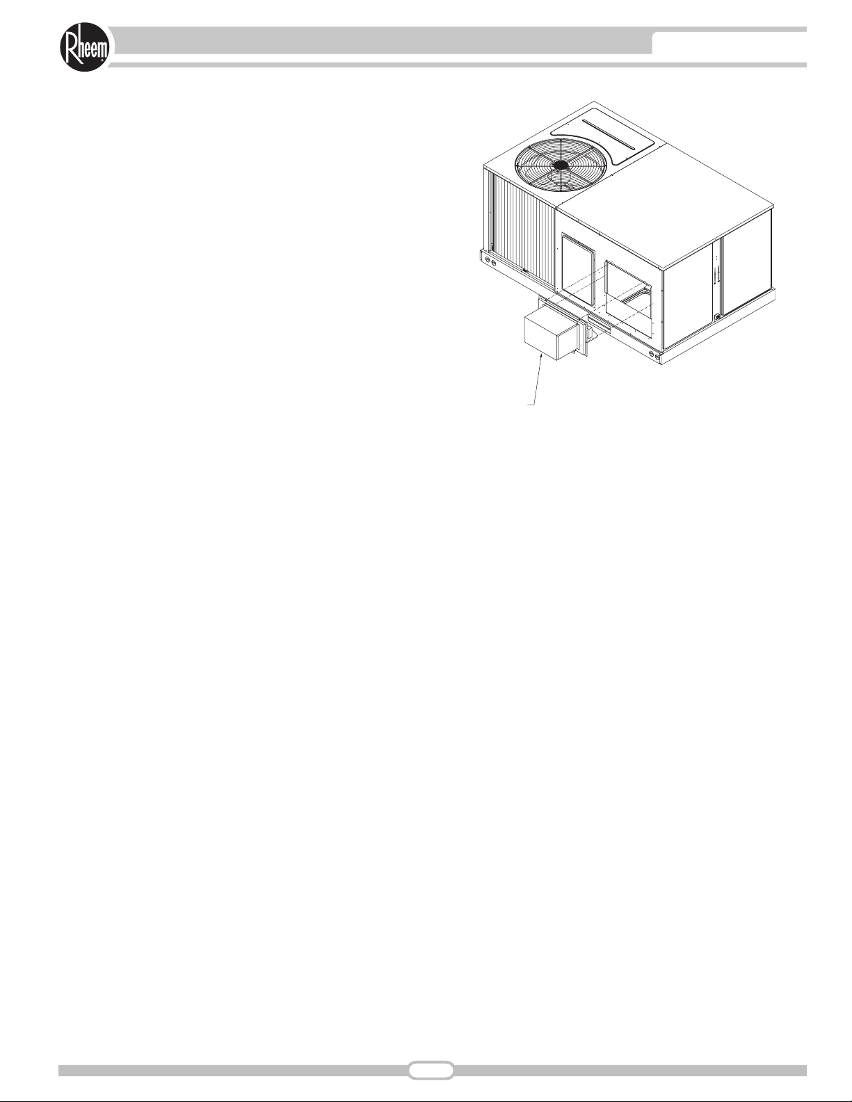
Heater Kits
Electric Heater Kits are designed for field
installation using either single-point power
wiring or dual circuit wiring. Low voltage
plugs are provided to allow for quick
connection to the unit. Removing a blockoff panel on the unit allows the heater
elements to be inserted into the supply air
down stream from the indoor coil and
supply air blower.
[ ] Designates Metric Conversions
Model Number Identifier:
23
INTRODUCTIONACCESSORIES—SJNL- SERIES
Page 24

ROOFCURBS (Full Perimeter)
■
Rheem’s new roofcurb design can be utilized on
5 through 6 ton [17.6-21.1 kW] models.
■
Two available heights (14" [356 mm] and
24" [610 mm]) for ALL models.
■
Quick assembly corners for simple and fast assembly.
■
Opening provided in bottom pan to match the
“Thru the Curb” electrical connection opening
provided on the unit base pan.
■
2" [51 mm] x 4" [102 mm] Nailer provided.
■
Insulating panels provided.
■
Sealing gasket (28" [711 mm]) provided
with Roofcurb.
■
Packaged for easy field assembly.
TYPICAL INSTALLATION
24
ACCESSORIES
[ ] Designates Metric Conversions
Roofcurb Model Height of Curb
RXKG-CAD14 14" [356 mm]
RXKG-CAD24 24" [610 mm]
Page 25

ROOFCURB CONFIGURATION FOR
SJNL 6 TON [21.1 kW] MODELS
ROOFCURB CONFIGURATION FOR
SJNL 5 TON [17.6 kW] MODELS
[ ] Designates Metric Conversions
Note: Roofcurb kits are the same for all models. (Figures above show locations for cross members that are model specific)
ROOFCURBS (Cont.)
25
ACCESSORIES
Page 26

■
Features Honeywell Controls
■
Available factory installed or field accessory
■
Gear Driven Direct Drive Actuator
■
Fully Modulating (0-100%)
■
Low Leakage Dampers
■
Horizontal or Downflow Applications
■
Slip-In Design for Easy Installations
■
Plug-In Polarized 12-pin Electrical Connections
■
Pre-configured—No Field Adjustments Necessary
■
Standard Barometric Relief Damper Provided
■
Single Enthalpy with Dual Enthalpy Upgrade Kit
■
CO2Input Sensor Available (Field Installed)
■
Economizer slips in complete for Downflow or
Horizontal Duct application
■
Field Assembled Hood Ships with Economizer
■
Optional Remote Minimum Position (Honeywell
#S963B1128) is Available from ProStock
[ ] Designates Metric Conversions
ECONOMIZERS
RXRD-MECM3—5 Ton [17.6 kW] Models Single Enthalpy with Barometric Relief
RXRD-TCCM3—6 Ton [21.1 kW] Models Single Enthalpy with Barometric Relief
RXRX-AV02—Dual Enthalpy Kit
5-6 Ton [17.6-21.1 kW] Models
Optional CO
2
Sensor
RXRX-AR02—5-6 Ton [17.6-21.1 kW] Models
SJNL 5 Ton [17.6 kW] Models
SJNL 6 Ton [21.1 kW] Models
26
ACCESSORIES
Page 27
FRESH AIR DAMPER
SJNL 5-6 Ton [17.6-21.1 kW] Models
RXRF-FCA1 (Manual)
RXRF-FCB1 (Motorized)
[ ] Designates Metric Conversions
27
ACCESSORIES
I319.DGN
FRESH AIR DAMPER
Page 28

DUCT ADAPTERS (6 Ton [21.1 kW] Models)
Rectangular to Round Transitions (Downflow)
RXMC-CC04 20" [508 mm] Round
[ ] Designates Metric Conversions
DUCT ADAPTERS (5 Ton [17.6 kW] Models)
Rectangular to Round
Transitions (Downflow)
RXMC-CB03 – 18" [457 mm] Round
Available in 18 inch round
to fit all units. Drops
into and secures to
RXKG- Series Roofcurbs.
For use with
Concentric Diffusers.
28
ACCESSORIES
Accessory Model No. Size in. [mm]
RXMC-CB03 18 [457] Round
RXMC-CC04 20 [508] Round
Model Application Tons [kW]
5 [17.6]
6 [21.1]
Page 29

SIDE DISCHARGE CONCENTRIC DIFFUSER
RXRN-FA60 (5 Ton [17.6 kW] Models)
RXRN-FA65 (6 Ton [21.1 kW] Model)
DIMENSIONAL DATA
ENGINEERING DATA
[ ] Designates Metric Conversions
For Use With Duct Adapter (RXMC)
29
ACCESSORIES
Model No. A B C D E F G H I J K
RXRN-FA60
RXRN-FA65
475/8"
[1210 mm]
475/8"
[1210 mm]
235/8"
[600 mm]
295/8"
[752 mm]
113/8"
[289 mm]
143/8"
[365 mm]
211/2"
[546 mm]
271/2"
[699 mm]
451/2"
[1156 mm]
451/2"
[1156 mm]
221/2"
[572 mm]
221/2"
[572 mm]
111/2"
[292 mm]
111/2"
[292 mm]
103/4"
[273 mm]
133/4"
[349 mm]
451/2"
[1156 mm]
451/2"
[1156 mm]
211/2"
[546 mm]
271/2"
[699 mm]
Model No. CFM [L/s]
1000 [472] .14 10-17 351 351 20
1200 [566] .17 11-18 421 421 20
1400 [661] .20 12-19 491 491 20
RXRN-FA60
RXRN-FA65
1600 [755] .24 12-20 561 561 20
1800 [850] .30 13-21 632 632 20
2000 [944] .36 14-23 702 702 20
2200 [1038] .40 16-25 772 772 20
2600 [1227] .17 24-29 669 669 20
2800 [1321] .20 25-30 720 720 25
3000 [1416] .25 27-33 772 772 25
3200 [1510] .31 28-35 823 823 25
3400 [1605] .37 30-37 874 874 30
Static
Pressure
Throw
Feet
Neck
Vel.
Jet
Vel.
71/8"
[181 mm]
81/8"
[206 mm]
Noise
Level
Duct
Size
18RD
20RD
Page 30

FLUSH MOUNT CONCENTRIC DIFFUSER
RXRN-FA70 (5 Ton [17.6 kW] Models)
RXRN-FA75 (6 Ton [21.1 kW] Model)
DIMENSIONAL DATA
ENGINEERING DATA
[ ] Designates Metric Conversions
For Use With Duct Adapter (RXMC)
30
ACCESSORIES
Model No. A B C D E F G H
RXRN-FA70
RXRN-FA75
475/8"
[1210 mm]
475/8"
[1210 mm]
235/8"
[600 mm]
295/8"
[752 mm]
131/2"
[343 mm]
165/8"
[422 mm]
21"
[533 mm]
27"
[686 mm]
45"
[1143 mm]
45"
[1143 mm]
221/2"
[572 mm]
221/2"
[572 mm]
111/4"
[286 mm]
111/4"
[286 mm]
Model No. CFM [L/s]
1000 [472] .14 15-20 391 694 20
1200 [566] .17 16-22 469 833 25
1400 [661] .20 17-24 547 972 30
RXRN-FA70
RXRN-FA75
1600 [755] .24 18-25 625 1111 30
1800 [850] .30 20-28 703 1250 35
2000 [944] .36 21-29 781 1389 40
2200 [1038] .40 22-30 859 1528 40
2600 [1227] .17 19-24 663 1294 30
2800 [1321] .20 20-28 714 1393 35
3000 [1416] .25 21-29 765 1492 35
3200 [1510] .31 22-29 816 1592 40
3400 [1605] .37 22-30 867 1692 40
Static
Pressure
Throw
Feet
Neck
Vel.
Jet
Vel.
101/2"
[267 mm]
131/2"
[343 mm]
Duct
Size
18RD
20RD
Noise
Level
Page 31

SAMPLE
SPECIFICATIONS
Unit shall be completely factory assembled
and performance tested to provide the
required cooling and heating functions suitable for outdoor installations. Unit shall be
UL/cUL listed and rated in accordance to
AHRI Standard 210.
Cabinet
Unit casing, base pan and framework shall
be manufactured of galvanized sheet metal
primed and finished with powder paint
capable of withstanding a 1000-hour salt
spray test per ASTM B 117. Unit interior
cabinet surfaces shall be insulated with a
minimum 1/2-inch thick foil faced insulation.
Access panels shall be easily removable
providing access to the blower, filter, heating compartment, and compressor/control
box. Unit base rails shall be provided with
fork insertion slots and rigging holes. Condensate drain pan shall be of sloped design
to conform to ASHRAE 62. Unit shall be
supplied ready for vertical airflow and be
easily convertible to horizontal airflow at or
before installation.
Compressor(s)
Unit shall be provided with fully hermetic
scroll compressor(s) with internally protected safety controls.
Coils
The evaporator and condenser coils shall
be fabricated of copper tubes with mechanically bonded aluminum plate fins. They
shall be pressure tested prior to assembly
into the unit, and electronically leak tested
after assembly.
Condenser Fan
A single direct drive propeller fan shall discharge air vertically upward. The fan motor
shall be permanently lubricated and have
built-in overload protection.
Evaporator Blower
A single, double inlet, centrifugal wheel shall
rotate in permanently lubricated ball bearings. The wheel shall be made from steel
with corrosion resistant finish and shall be
statically and dynamically balanced.
ACCESSORIES
ROOF CURB
Curb shall be full perimeter type, complying
with the standards of the National Roofing
Contractors Association. Design shall provide for drop-in of supply and return ducts
prior to setting unit, and include an insulating panel for the rest of the curb area.
Economizer
Economizer shall be completely assembled
for field installation. Unit shall include all
controls and dampers including the barometric relief damper.
Manual Fresh Air Damper
Damper shall consist of damper and rainhood which is manually preset to admit up
to 35% of outside air for field installation.
Motorized Fresh Air Damper
Damper shall consist of motor, damper, and
rainhood which can admit up to 35% of outside air for field installation.
Electric Heat Kits
Electric heat kits shall be available in a
wide range of capacity with branch circuit
fusing allowing single point wiring. Kits shall
be UL/cUL approved. Each kit shall be
offered as a field or factory installed option.
Pressure Controls
High and low pressure controls are standard for all models.
Low Ambient Control
Low ambient control shall be provided to
cycle the condenser fan in response to
condensing pressure and allow operation
to 0 degrees F. The option shall be field or
factory installed.
Time Delay Control
Time delay control shall be provided to
prevent the compressor from restarting 5
minutes after shutdown.
Louver Panel Kits
Field or factory installed louver kits shall
be provided for condenser coil protection
against hail or flying debris.
31
MECHANICAL SPECIFICATIONS
Page 32

32
WIRING SCHEMATICS—SJNL- SERIES
Page 33

33
WIRING SCHEMATICS—SJNL- SERIES
Page 34

34
NOTES
Page 35

35
NOTES
Page 36

Before proceeding with installation, refer
to installation instructions packaged
with each model, as well as complying
with all Federal, State, Provincial, and
Local codes, regulations, and practices.
Rheem Heating,
Cooling and
Water Heating
P.O. Box 17010, Fort Smith, AR 72917
“In keeping with its policy of continuous progress and product improvement, Rheem reserves the right to make changes without notice.”
PRINTED IN U.S.A. 8-10 DC FORM NO. EXP11-773
Supersedes Form No. EXP11-773 Rev. 1
 Loading...