

Page 1
INSTALLATION INSTRUCTIONS
LOW AMBIENT CONTROL KIT
(-)KNL/LNL-G090 THRU G300 MODELS
RXRZ-A06
!
Recognize this symbol as an indication of Important Safety Information!
!
WARNING
THESE INSTRUCTIONS ARE INTENDED AS AN AID TO QUALIFIED SERVICE PERSONNEL FOR PROPER INSTALLATION,
ADJUSTMENT, AND OPERATION OF THIS KIT. READ THESE INSTRUCTIONS THOROUGHLY BEFORE ATTEMPTING INSTALLATION, ADJUSTMENT, OR OPERATION. FAILURE TO FOLLOW THESE INSTRUCTIONS CAN RESULT IN IMPROPER INSTALLATION, ADJUSTMENT, SERVICE OR MAINTENANCE, POSSIBLY RESULTING IN FIRE, ELECTRICAL SHOCK, PROPERTY DAMAGE,
PERSONAL INJURY, OR DEATH.
PARTS LIST
DESCRIPTION PART NUMBER QUANTITY
Low Ambient Control AS-103034-01 2
Accessory Relay 42-102234-01 1
Relay Mounting Screws 63-22153-04 2
Relay Coil Wire (blue) AS-50204-29-AJ 1
Relay Coil Wire (brown) AS-50207-29-AJ 1
Relay Wire (black) AS-50230-27-DD 2
Wire Tie 64-17606-01 2
AR - Label 92-19438-43 1
!
WARNING
BEFORE BEGINNING ANY MODIFICATION, BE SURE MAIN
DISCONNECT SWITCH IS IN THE “OFF” POSITION. FAILURE TO DO SO CAN CAUSE ELECTRICAL SHOCK
RESULTING IN PROPERTY DAMAGE, PERSONAL INJURY
OR DEATH. TAG DISCONNECT WITH A SUITABLE WARNING LABEL
TOOLS/SUPPLIES REQUIRED
A. 1/4” flat blade screwdriver (to open control box door).
B. 1/8” flat blade screwdriver (to connect wires on Outdoor Fan
Motor Controller terminal block).
C. 1/4” nut driver.
D. 5/16” nut driver.
E. 7/16” open end wrench.
F. 9/16” open end wrench.
G. Box Cutter (to open packaging).
LOW AMBIENT SWITCH INSTALLATION
A. Shut off power to unit (see warning above).
B. Open blower access door. Refer to Figure 2.
C. Remove brass cap from Schrader valve located in the refrig-
erant liquid line near the TXV. Refer to Figure 2.
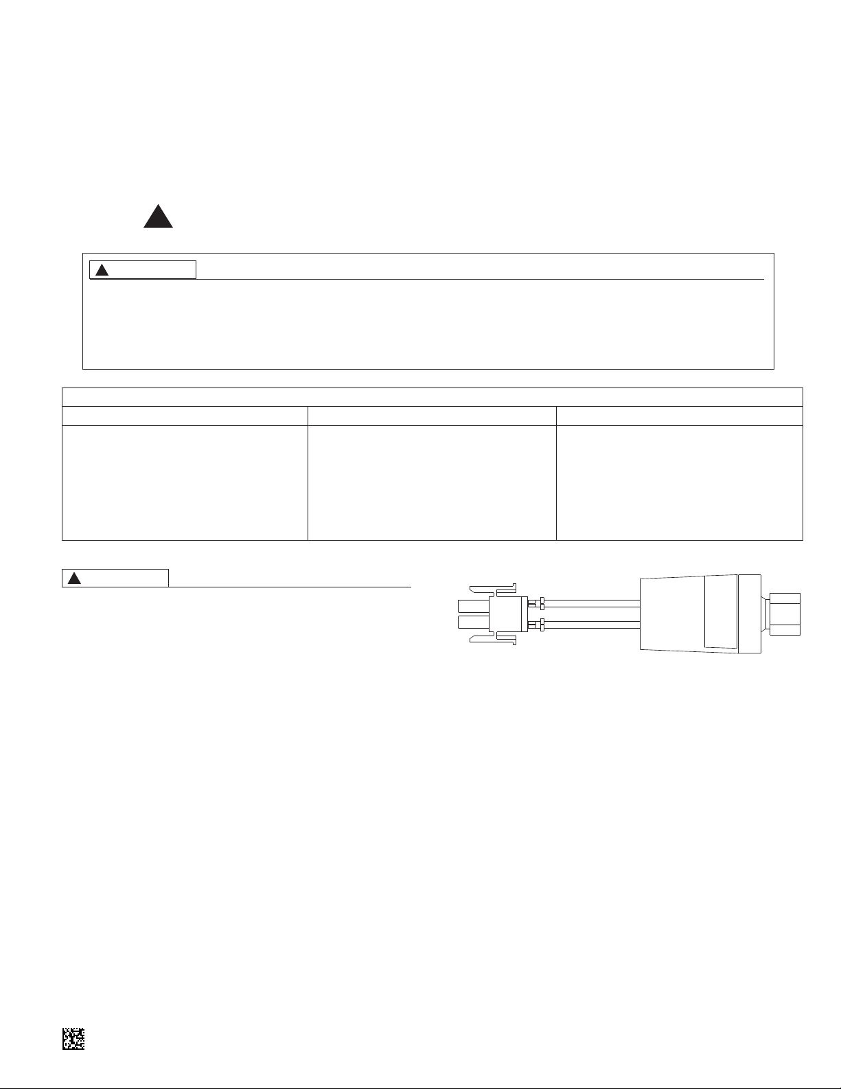
FIGURE 1. LOW AMBIENT CONTROL
D. Quickly screw Low Ambient Control (see Figure 1) onto
Schrader valve. Use 9/16” open end wrench on Low
Ambient Control and torque to 8-10 ft/lbs with 7/16” open
end backup wrench on the Schrader valve. CAUTION: If a
backup wrench is not used serious damage to the
equipment or personal injury may occur. Do not over
tighten connection.
E. Repeat C. through D. for second system.
F. Check all connections for refrigerant leaks and repair as
necessary.
G. Remove factory installed low ambient jumper wires located
inside the blower compartment. Connect female 2-wire connectors from unit to male 2-wire connectors on low ambient
controls. Note: Use the unit wiring diagram to verify the
low ambient control for refrigerant circuit #1 is connected to the electrical control circuit for compressor #1. A
low ambient control is required for each compressor.
H. Close blower access door.
92-105317-01-00
Page 2
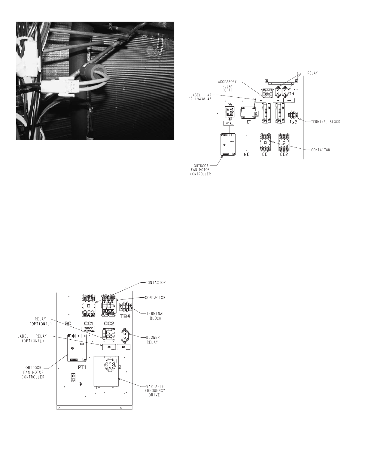
FIGURE 2. LOW AMBIENT CONTROL INSTALLATION.
ST-A1229-01-00
ST-A1229-02-00
TORQUE CONTROL 8-10 FT. LBS. DO NOT OVER TORQUE
OR DAMAGE TO CONTROL WILL RESULT.
E. For KNL/LNL-G180/240/300 models (Figure 4):
a. Attach one black wire (AS-50230-27-DD) to Accessory
Relay terminal AR(3) and Outdoor Fan Motor Controller
terminal OFMC (LINE 2).
b. Attach one black wire (AS-50230-27-DD) to AR(1) and
compressor contactor CC1 (T1).
LOW AMBIENT SWITCH INSTALLATION
A. Open control section door.
B. Remove control panel cover.
C. Mount Accessory Relay (AR) to control panel to the left of
the Blower Relay with 2 screws provided. Apply AR Label
(92-19438-43) to control panel (See Figure 3 or Figure 4).
D. For KNL/LNL-G090/120/151 models (Figure 3):
a. Attach one black wire (AS-50230-27-DD) to Accessory
Relay terminal AR(1) and Outdoor Fan Motor Controller
(OFMC) terminal (LINE 2).
b. Attach one black wire (AS-50230-27-DD) to AR(3) and
Terminal Block TB4 (1).
ST-A1229-01-00
FIGURE 3. CONTROL PANEL
ST-A1229-02-00
FIGURE 4. CONTROL PANEL
F. Attach Blue wire (AS-50204-29-AJ) to AR coil (left terminal)
and Outdoor Fan Motor Controller (OFMC) terminal block
(REHEAT).
G. Attach Brown wire (AS-50207-29-AJ) to Outdoor Fan Motor
Controller (OFMC) terminal block (COMMON) and AR coil
(right terminal).
H. Use unit wiring diagram to verify proper connections.
I. Secure loose wires with wire ties.
J. Replace control panel cover and close control section door.
UNIT OPERATIONAL CHECK
A. Restore power and check unit for proper operation.
B. Outdoor fan cycles off when liquid pressure drops below
250, ± 10 PSIG.
C. Outdoor fan cycles on when liquid pressure rises above
450, ± 10 PSIG.
D. In reheat mode with the low ambient control option, the
relay bypasses the function of the low ambient control on
refrigerant circuit #1 so that the refrigerant liquid line tem-
perature is controlled by the outdoor fan motor controller
(OFMC) instead of the low ambient control.
This accessory is used when unit operation is required during
low ambient conditions. Installation of this control provides a
means of de-energizing the condenser fan motor. This permits
the suction (low side) to remain above the point which can cause
icing of evaporator (inside coil).
NOTE: Liquid line pressure for multiple compressors must all
drop below 250 before fans will cycle off and above 450 before
fans will cycle on.
Page 3

FIGURE 5. TYPICAL WIRING DIAGRAM
ST-A1229-03-00
ST-A1229-03-00
Page 4

CM 0814
 Loading...