

Rheem RXRX-AL01, RXRX-AL02 Installation Manual
INSTALLATION INSTRUCTIONS
Parts List RXRX-AL01 RXRX-AL02
Description Part Number Quantity
Part Number Quantity
WIRE NUT 45-18058-01 1 45-18058-01 2
ANTI CYCLE DELAY CONTROL 47-104319-01 1 AS-104325-01 1
HIGH PRESSURE CONTROL 47-102290-01 1 47-102290-01 2
SCREW-SHEET METAL 6-20 X 3/4 63-22153-0ϳ 4 63-22153-07 4
WIRE TIE 64-17606-01 1 64-17606-01 1
ADAPTER TEE 83-21457-02 1 83-21457-02 2
INSTALLATION INSTRUCTIONS 92-104323-01 1 92-104323-01 1
WIRING DIAGRAM 90-104329-01 1 90-104329-02 1
WIRE HARNESS AS-104330-01 1 AS-104330-03 1
WIRE HARNESS AS-104330-02 1 AS-104330-04 1
LOCKOUT PROTECTION MODULE KIT
RXRX-AL01 7.5, 10.0-TON
RXRX-AL02 12.5, 15.0 & 20-TON
GAS, ELECTRIC & SELF-CONTAINED PACKAGED UNIT
Recognize this symbol as an indication of Important Safety Information!
!
!
WARNING
THESE INSTRUCTIONS ARE INTENDED AS AN AID TO QUALIFIED SERVICE PERSONNEL FOR PROPER
INSTALLATION, ADJUSTMENT AND OPERATION OF THIS KIT. READ THESE INSTRUCTIONS THOROUGHLY
BEFORE ATTEMPTING INSTALLATION, ADJUSTMENT, OR OPERATION. FAILURE TO FOLLOW THESE
INSTRUCTIONS CAN RESULT IN IMPROPER INSTALLATION, ADJUSTMENT, SERVICE OR MAINTENANCE,
POSSIBLY RESULTING IN FIRE, ELECTRICAL SHOCK, PROPERTY DAMAGE, PERSONAL INJURY OR DEATH
!
WARNING
BEFORE BEGINNING ANY MODIFICATION, BE SURE MAIN
DISCONNECT SWITCH IS IN THE “OFF” POSITION. FAILURE TO DO SO CAN CAUSE ELECTRICAL SHOCK
RESULTING IN PROPERTY DAMAGE, PERSONAL INJURY
OR DEATH. TAG DISCONNECT WITH A SUITABLE WARNING LABEL.
TOOLS/SUPPLIES REQUIRED
a. 1/4” nut driver.
b. wire cutters/stripper.
c. handheld voltmeter/ohmmeter.
d. electrical tape.
e. 9/16” open end wrench
f. 7/16” open end wrench
g. power drill.
GAS, ELECTRIC AND
SELF-CONTAINED UNITS
RXRX-AL01 INSTALLATION
7.5 AND 10.0-TON
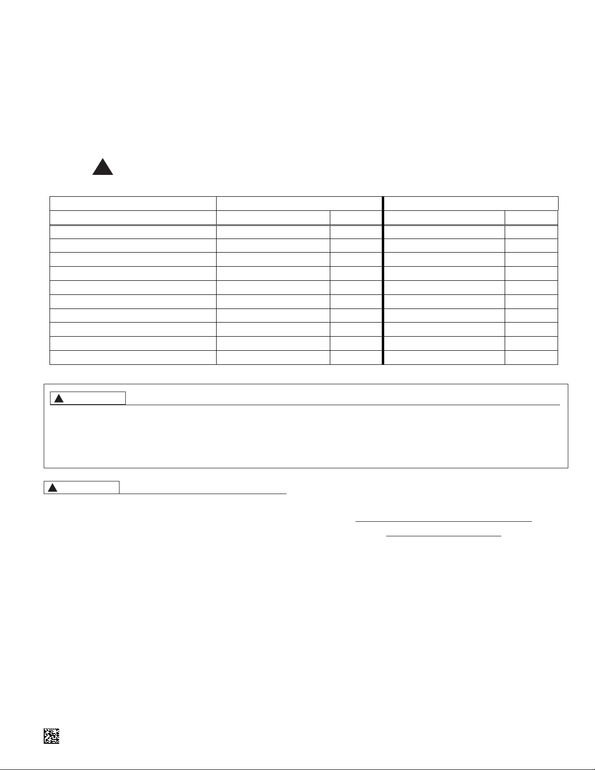
1. HIGH PRESSURE SWITCH INSTALLATION
a. Shut off power to unit (see warning above).
b. Remove blower compartment access panel.
c. Remove brass cap from Schrader valve located on liquid
line (see Figure 1) that is normally used for the low ambient
control accessory. If a low ambient control accessory is
already installed, it must be removed first.
d. Using the 9/16” open end wrench, assemble the High
Pressure Control to the Adapter Fitting that does not have a
valve core. Always “backup” the fitting when tightening using
the 7/16” open end wrench. Attach pressure control/adapter
fitting onto liquid line access fitting and torque to 8-10 ft./lbs.
(see Figure 1) using the same wrenches and technique.
e. If a low ambient control accessory is used, install it next
using the same torque settings.
SUPERSEDES 92-104323-01-00
.
92-104323-01-01
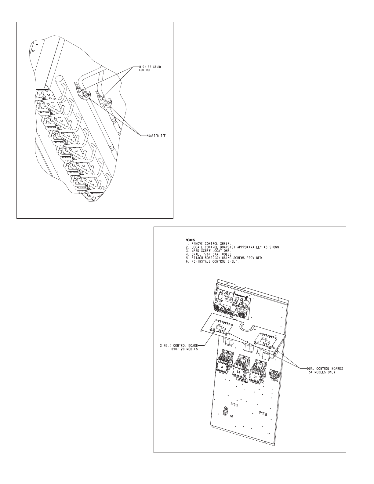
FIGURE 1
(Note: 7.5 and 10 ton models will have one liquid line)
2. SWITCH ELECTRICAL CONNECTIONS
a. Route wires on the new auto-reset refrigerant high pressure
switch toward the unit control box by placing them across
the wire trough over the indoor coil. The indoor top panel
may need to be partially lifted by removing fasteners to complete this step. The two-pin connector (Plug 22) on Figure 4
must be visible in the control box of the unit when finished.
b. Remove the existing manual reset refrigerant high pressure
switch from the electrical circuit by cutting the wire leads to
the original switch and connecting the wire leads still in the
circuit together with a wire nut. DANGER: The remaining
steps must be completed to provide overpressure protection!!!
c. Use electrical tape over the wirenut to secure and provide
moisture protection.
d. Secure loose wires with wire tie.
e. Replace blower compartment access cover.
3. ANTI-CYCLE DELAY CONTROL
3. INSTALLATION
a. Shut off power to unit (see warning above).
b. Remove control box access panel.
c. Remove control box cover.
d. Remove control shelf (see Figure 2).
e. Drill holes (see Figure 2) and install new control board on
control shelf with included fasteners.
f. Reinstall control shelf.
FIGURE 2
2

4. CONTROL WIRING CONNECTIONS
a. Using the wire harnesses provided with the kit, make the
electrical connections as shown on the wiring diagram.
1. Remove the yellow 24 volt wire from the compressor contactor coil (CC1) and attach it to the input “Y” on the AntiCycle Delay Control.
2. Connect the purple wire from PL8 to CC1 coil where the
yellow wire was removed in the previous step (see Figure
4).
b. Replace control box cover.
c. Paste included Anti-Cycle Delay Control wiring diagram on
control box cover near the unit wiring diagram.
d. Replace control box access panel.
e. Restore power to unit and check for proper operation.
GAS, ELECTRIC AND
SELF-CONTAINED UNITS
RXRX-AL02 INSTALLATION
12.5-TON
1. INSTALLATION OF HIGH PRESSURE
1. SWITCHES
a. Shut off power to unit (see warning above).
b. Remove blower compartment access panel.
c. Remove brass cap from Schrader valve located on refriger-
ant circuit #1 liquid line (see Figure 1) that is normally used
for the low ambient control accessory. If the low ambient
control is already installed, it must be removed first.
d. Using the 9/16” open end wrench, assemble the High
Pressure Control to the Adapter Fitting that does not have a
valve core. Always “backup” the fitting when tightening using
the 7/16” open end wrench. Attach pressure control/adapter
fitting onto liquid line access fitting and torque to 8-10 ft./lbs.
(see Figure 1) using the same wrenches and technique.
e. If a low ambient control accessory is used, install it next
using the same torque settings.
f. Repeat steps “c” through “e” above for refrigerant circuit #2
liquid line.
2. SWITCH ELECTRICAL CONNECTIONS
a. Route wires on the new auto-reset refrigerant high pressure
switches toward the unit control box by placing them across
the wire trough over the indoor coil. The indoor top panel
may need to be partially lifted by removing fasteners to com-
plete this step. The two-pin connectors (Plug 22 & Plug 23)
on Figure 5 must be visible in the control box of the unit
when finished.
b. Remove the existing manual reset refrigerant high pressure
switches from the electrical circuit by first cutting the wire
leads for refrigerant circuit #1 and connecting the wire leads
still in the circuit together with a wire nut. Repeat for refriger-
ant circuit #2. DANGER: The remaining steps must be
completed to provide overpressure protection!!!
c. Use electrical tape over the wire nuts to secure and provide
moisture protection.
d. Secure loose wires with wire tie.
e. Replace blower compartment access cover.
3. ANTI-CYCLE DELAY CONTROL
3. INSTALLATION
a. Shut off power to unit (see warning above).
b. Remove control box access panel.
c. Remove control box cover.
d. Remove control shelf (see Figure 2).
e. Remove control boards from control board assembly without
disturbing attached wiring.
f. Discard sheet metal base from control board assembly.
g. Drill holes (see Figure 2) and install two new control boards
on control shelf with included fasteners.
h. Reinstall control shelf.
4. CONTROL WIRING CONNECTIONS
a. Using the wire harnesses provided with the kit, make the
electrical connections as shown on the wiring diagram.
1. Remove the yellow 24 volt wire from the compressor con-
tactor coil (CC1) and attach it to the input “Y” on the Anti-
Cycle Delay Control.
2. Connect the purple wire from PL8 to CC1 coil where the
yellow wire was removed in the previous step (see ACD1 on
Figure 5). The orange 24 volt wire that originally went to the
compressor contactor (CC2) is now the input “Y” to the sec-
ond stage Anti-Cycle Delay Control (ACD2) board.
b. Verify Plug 20 & Plug 22 are connected to the refrigerant
high pressure switch on refrigerant circuit #1.
c. Verify Plug 21 & Plug 23 are connected to the refrigerant
high pressure switch on refrigerant circuit #2.
d. Replace control box cover.
e. Paste included Anti-Cycle Delay Control wiring diagram on
control box cover near the unit wiring diagram.
f. Replace control box access panel.
g. Restore power to unit and check for proper operation.
GAS, ELECTRIC AND
SELF-CONTAINED UNITS
RXRX-AL02 INSTALLATION
15.0 AND 20.0-TON
1. HIGH PRESSURE SWITCH INSTALLATION
a. Shut off power to unit (see warning above).
b. Open blower compartment access door.
c. Remove brass cap from Schrader valve located on refriger-
ant circuit #1 liquid line (see Figure 1) that is normally used
for the low ambient control accessory. If the low ambient
control is already installed, it must be removed first.
d. Using the 9/16” open end wrench, assemble the High
Pressure Control to the Adapter Fitting that does not have a
valve core. Always “backup” the fitting when tightening using
the 7/16” open end wrench. Attach pressure control/adapter
fitting onto liquid line access fitting and torque to 8-10 ft./lbs.
(see Figure 1) using the same wrenches and technique.
e. If a low ambient control accessory is used, install it next
using the same torque settings.
f. Repeat steps “c” through “e” above for refrigerant circuit #2
liquid line.
3
 Loading...