How it Works
Log In / Sign Up
Buy Points
How it Works
FAQ
Contact Us
Questions and Suggestions
Users
Rheem
Loading...
R
RTH-53XN
RTH-74XN-1
2
RUSG75-40BP
RUSG75-48BP
RUTG2-42PVN
RUTG2-42PVP
RUTG2-53PVN
RUTG2-53PVP
RUTG2-53XN
RUTG2-53XP
RUTG-53X
RUTG-66DV
RUTG-74X
RUUD 12KW
RUUD 15KW
RUUD 18KW
RUUD 6KW
RUUD 6KW THRU 18 KW
RUUD 9KW
RUUD Commercial Booster
RUUD Commercial StorageTanks
Ruud Eclipse ME105
Ruud Eclipse ME85
RUUD Electric Commercial Water Heater
Ruud GT-199DVN-1
Ruud GT-199PVN-1
Ruud GT-199XN-1
Ruud PowerPack ASME E12A
Ruud PowerPack ASME E20A
Ruud PowerPack ASME E30A
Ruud PowerPack ASME E40A
RW1T
2
RXGJ-FP33
RXGJ-FP34
RXGY-D05
RXGY-D06
RXGY-E02
RXGY-E02A
RXGY-E03
RXGY-E03A
RXGY-E03A-E02A
RXGY-G01
RXHK-A01
RXID-AW90A
RXIH-AB12A
RXIH-AB17A
Rxih-as06a
2
Rxih-as09a
2
Rxih-as12a
2
RXJJ-CC Series
RXKG
RXMD-B04
RXQJ-B15J
RXRX-AL01
RXRX-AL02
RXRZ-A06
RXRZ-B01
RXRZ-C02
S
S25
SE40M12AAH
SE40M12TAH
SE50M12AAH
SE50M12TAH
SE50T12AAH
SE50T12TAH
SE80T12TAH
SEREGE
Series
SG Series
Side Inlet - Direct Vent Gas
Side Inlet Gas
Side Inlet Gas Water Heaters
Single and Double Element Models
Single Element
2
SJNL
SL50
SLC50
SMARTEC ECONET
SMUL 12
SMUL 18
SMUL 24
SMUL 30
SMUL 36
SMUL 48
SMUL 60
Solaraide
Solaraide RS47-21BP
Solaraide RS80-42BP
Solaraide Series
Solar Controller Kit
Solar Hiline 52D180
Solar Hiline 52D300
Solar Hiline Water Heater
Solar Loline Conversion Kit Electric Water Heater
Solar Loline Conversion Kit Electric Wter Heater
Solar Loline Water Heater
Solar Premier Loline
2
Solar Premier Loline 590160
Solar Thermosiphon Water Heater
SP20286
Loading...
Loading...
Nothing found
RXKG
Installation Manual
4 pgs
150.12 Kb
0
Table of contents
Loading...
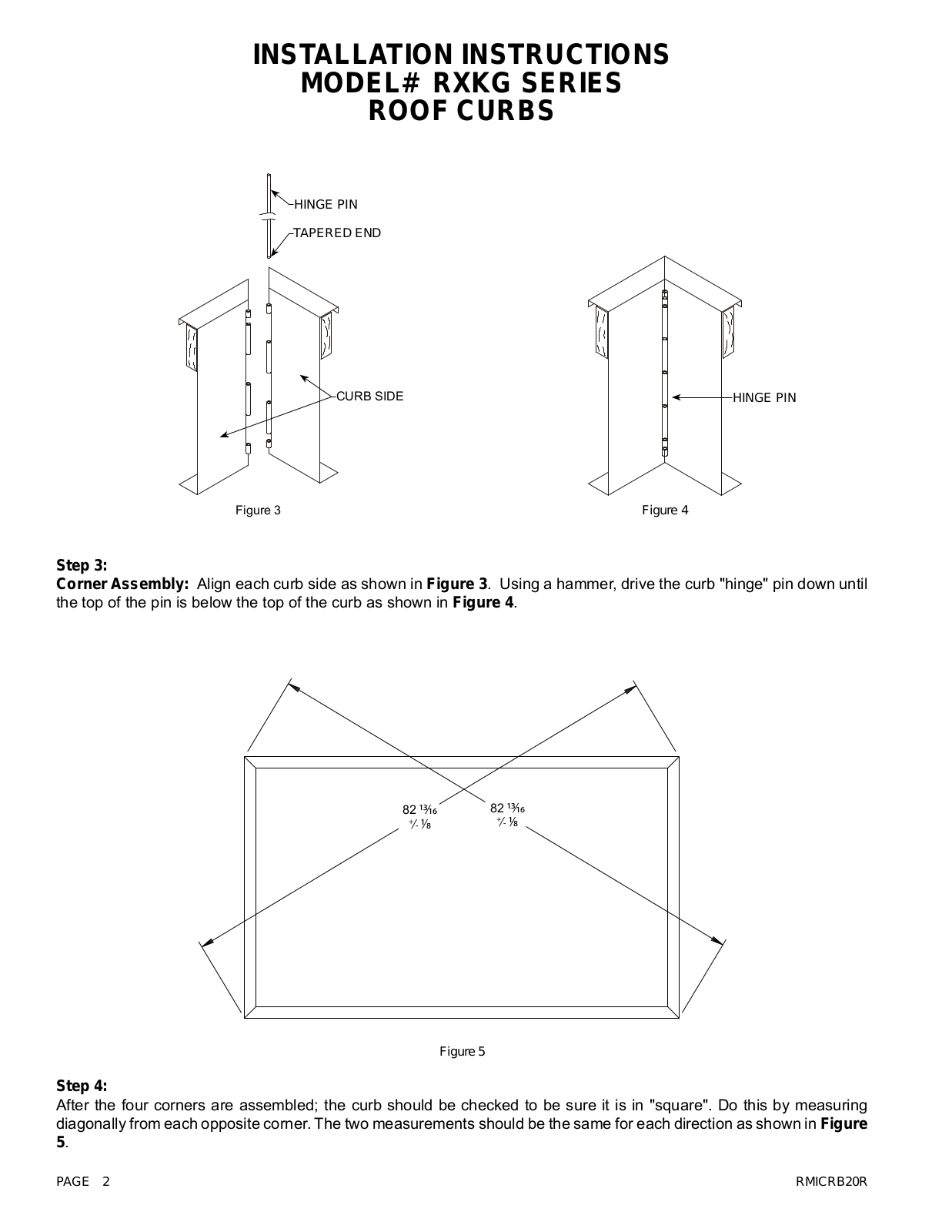
Rheem RXKG Installation Manual
...
Rheem Installation Manual
Download
Specifications and Main Features
Frequently Asked Questions
User Manual
Download
Loading...
+
2
hidden pages
Unhide
You need points to download manuals.
1 point = 1 manual.
You can buy points or you can get point for every manual you upload.
Buy points
Upload your manuals