

Page 1
INSTALLATION INSTRUCTIONS
. FOR
AUXILIARY ELECTRIC HEATER KITS
A. Recognizethissymbolas an indicationofImportantSafetyInformationl
IMPORTANT: TO ENSUREPROPBRINSTALLAnON ANDOPBRATION,PLBASEREADALL INSTRUCTIONSPRIORTO
ASSBMBLY,INSTALLATION,OPERATION,MAINTENANCBORREPAIROFnus PRODUCT. AFTERUNPACKING11IB
HEATERKIT, INSPECTALL PARTSFORDAMAGBPRIORTOINSTALLATIONANDSTARTUP. .
INTRODUCfION
The information contained in these instructions has been prepared
to assist in the proper installation and operation of the auxiliary
electric heaters. Improper installation can result in unsatisfactory
opezation or dangerous conditions not covered I>ythe unit wammty
and may invalidate the Underwriters Laboratories recognition.
\
CHECKING PRODUCT RECEIVED
Upon receiving the heater kit, inspect it for any shipping damage.
Claims for damage should be tiled immediately with the shipping
company.
IChcclcheater kit model number to determine that it is the correct
series for the unit, as shown on the unit rating plate. and is of the
desired voltage and KW size.
APPLICATION
"'.
These-auxiliary-e1ectrie-resistance heater kits ar.e desi
insbiIIation in the discharge air compartment of the indoor blower.
Improper usage can cause results which may be dangecous. Do not
use heater kits other than those referenced on the unit rating plate.
Clearance to combustible material for the unit and fIrStthree (3)
feet of duct is "0" inches.
OPERATION
The heater elements are wired through controllers operated by the
24 volt thermostat circuit To insure blower operation, the blower
is also controlled by the heater controllers. The heater controllers
will turn the blower and first stage heater "on" first and will turn
the beater and blower "off" last when the thermostat is satisfied.
INDOORBLOWER SPEED
Refer to the blower airflow tables in the unit installation
instructionstoset the proper blower speed for your airflow and
static pressure requirements. .
A WARNING
DISCONN~CT ALL POWER BEFORE STARTING
REATER KIT INSTAL~ TION. FAILURETO DOSO CAN
RESULTIN SEVER ELECTRICAL SHOCK OR DEATIL
ELECTRICAL WIRING
Field wiring must comply with the National Electrical Code (CBC
in Canada) and any local ordinances that may apply.
POWER WIRING
e unit has been in operation without an elec::tricheater kit
installed, it may be necessary to change the field installed
power wiring. The added current of the electric heater kit may
require larger gauge wiring than that required for the unit
alone. Refer to the unit rating plate or instaUation instructions
for the required supply circuit sim and overcurrent protection.
A wire sizing table follows for reference
2. It is important that proper electrical power is available at the
heater kit terminals. Voltage should Dotvary more than 10%
from that marked on the unit rating plate. Phase voltages must
bebalancedwithin3%. .
3. A properlysized disconnectswitch shall be located within
sight of the unit or as required by local codes. .
.
TOOLS NEEDED
The following tools can be helpful in installing the kits:
1. Slottedscrewdriversand5/16" nutdriver.
2. Some kits will require the use of alien wrenches.
3. Needle-nose pliers.
4. Wire cutters and strippers.
4. Power wiring must be run in grounded, rain-tight conduit.
5. Refertothe unit installationinstructionsfor power entry
location.Thehighvoltagefieldinstalledpowersupplycircuit
shouldbe connectedto the line side of the tenninal block
located on the heater kit. Consult the heater kit wiring
diagram.
Page 2
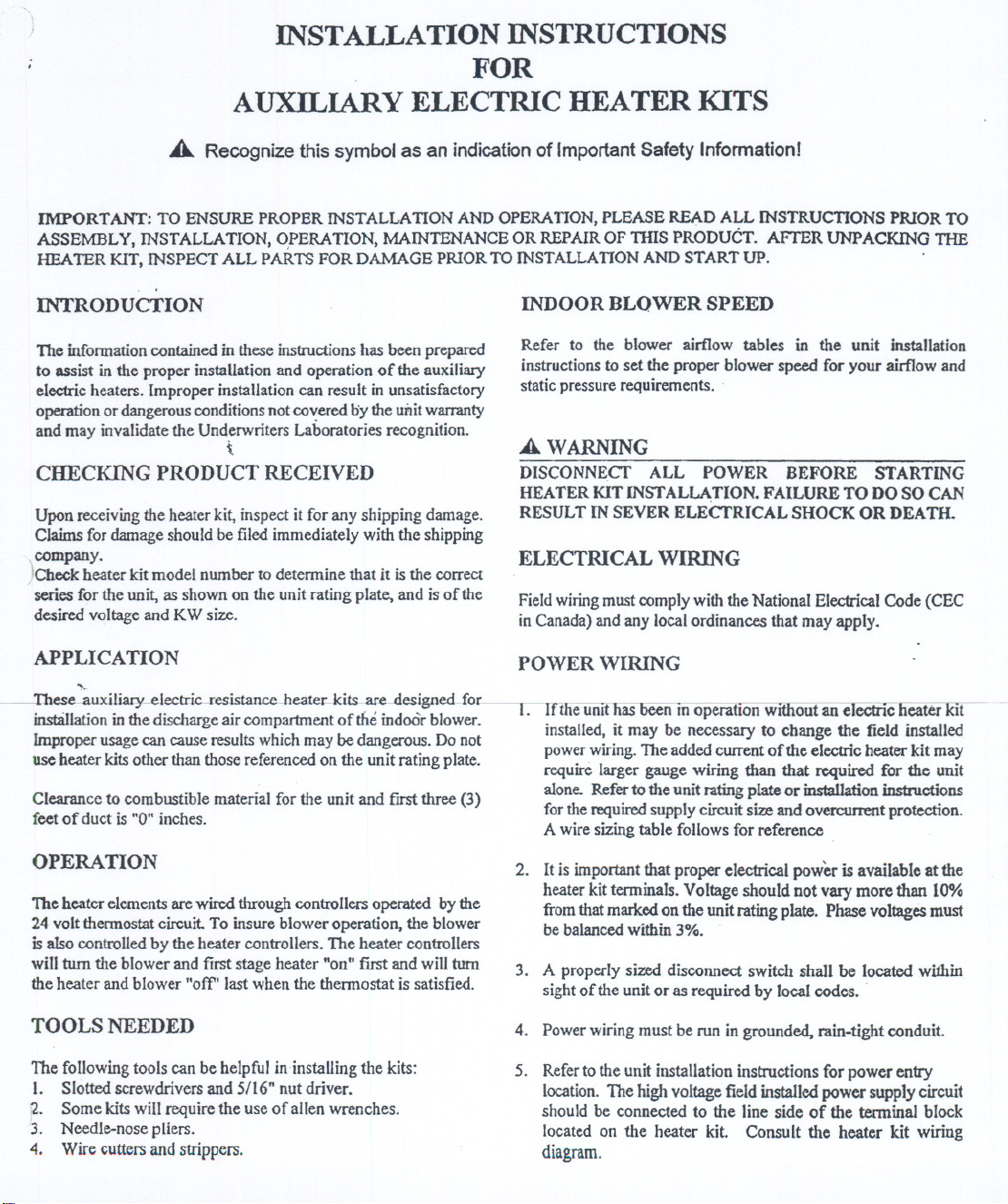
.ror 1I1::1U WSUUlauUU Ul 11I1 C:JCC\OC nc:aacr au" LUI1UW we
instructions below:
a.
Removing screws as required, open heater access door
and detach adjacent power entry panel.
b.
Remove wires to unit contactor (Ill, 11.2,lL3) ftom the
unit terminal block on the left side of the electric heat
compartment Remove and discard the terminal block
. and the adjacent ground l';1g.
c.
Remove the heater kit block-off panel and installthe
heaterkit in itspla~ using9ofthe 12screwspreviously
removed.
d.
Connect the unit contactor wires (Ill, IL2, IL3) to the
compressor fuse block on the heater kit
e.
Re-install the power entty panel & ~n con(Juit and the
proper size field w.iringthrough the opening in the panel.
f.
ColUlectfield wiring to the power tenninal block located
\
on the electric heater kit Connect ground wire to the
adjacent ground lug.
g. Connect heaterkit controlplug to the receptacleon the
controlwiringharness.
h. Check all electrical connections including factory wiring
within the unit and make sure all connections are tigh
and properly located.
i. -- Close heater access door and secure. With tbe screws
previously removed.
t AffiHeatel'-kit-wiring4iagmm-m-inside-()k6ntro1--1filtcr
accessdoor.
I. AU lOWvOltage wanng mUStoe roUted mto the lOWvOltage
connection area and not into the power wiring or heater conCroI
area.
2. For thermostat low voltage connections, see unit installation
Instructions.
3. Thennostat heat anticipator should be adjustable for a
minimumrangeof .10- 1.20. Typicalsettingsare as follows:
THERMOSTAT HEATANTICIPATORSETTlNG*
NUMBER OF STAGES
I Z
SE'ITlNG .7 .7&."
*NOTES
I. Nonnally.1hc firststage heathas a fixed$CUing.
2. Some chcrmostaIs have DOll!iustable second stage heat antidpator
setting indicator. Follow the instnlctions in these spc:cific
lhennostaU 10 get proper operation.
3. RqJlace the control box cover and control compartmentacccss panel
after all wiring is complctccl.
4. Chcclcunit for properopcwlon.
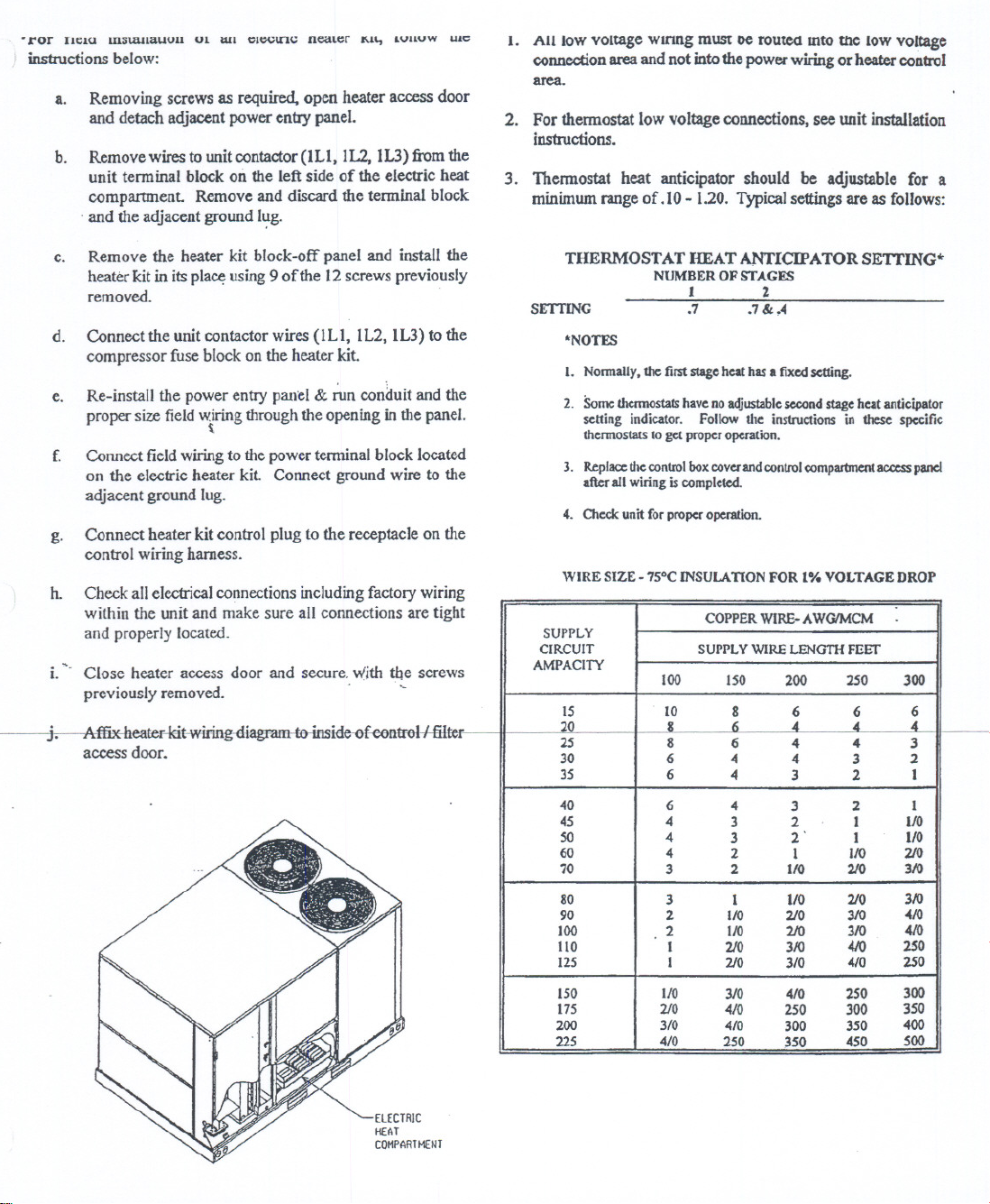
WIRE SIZE -7SOCINSULA110N FOR 1% VOLTAGE DROP
.
SUPPLY
CIRCUIT
AMPACITY
15
:20
25
30 6
35 6
40 6 4 3 2 I
45 4
SO 4
60 4
70
80 3
90 2 110 210
100 2 I/O 210
110
12S I 210 3/0 ...,0 250
150 110
175
200
225 'I/O
COPPERWIRE-AWG'MCM
SUPPLYWIRELENG1HFEET
100 ISO
10
I
8 6
3 2 110
I 210 310 <C/O
2/0
3/0 410
4 4
4
3 2 I
3
2
310 410 250
410
250
200 250 300
8 6 6 6
" ..
.. 4
3 2
2'
I
1 110 210
250
300
350
300 350
350
450
..
3 2
I
I/O 210
210 310
3/0 .c/O
3/0 .uo
..
3
I
VO
I/O
3/0
250
300
400
500
 Loading...