

Rheem RXID-AW90A Installation Manual
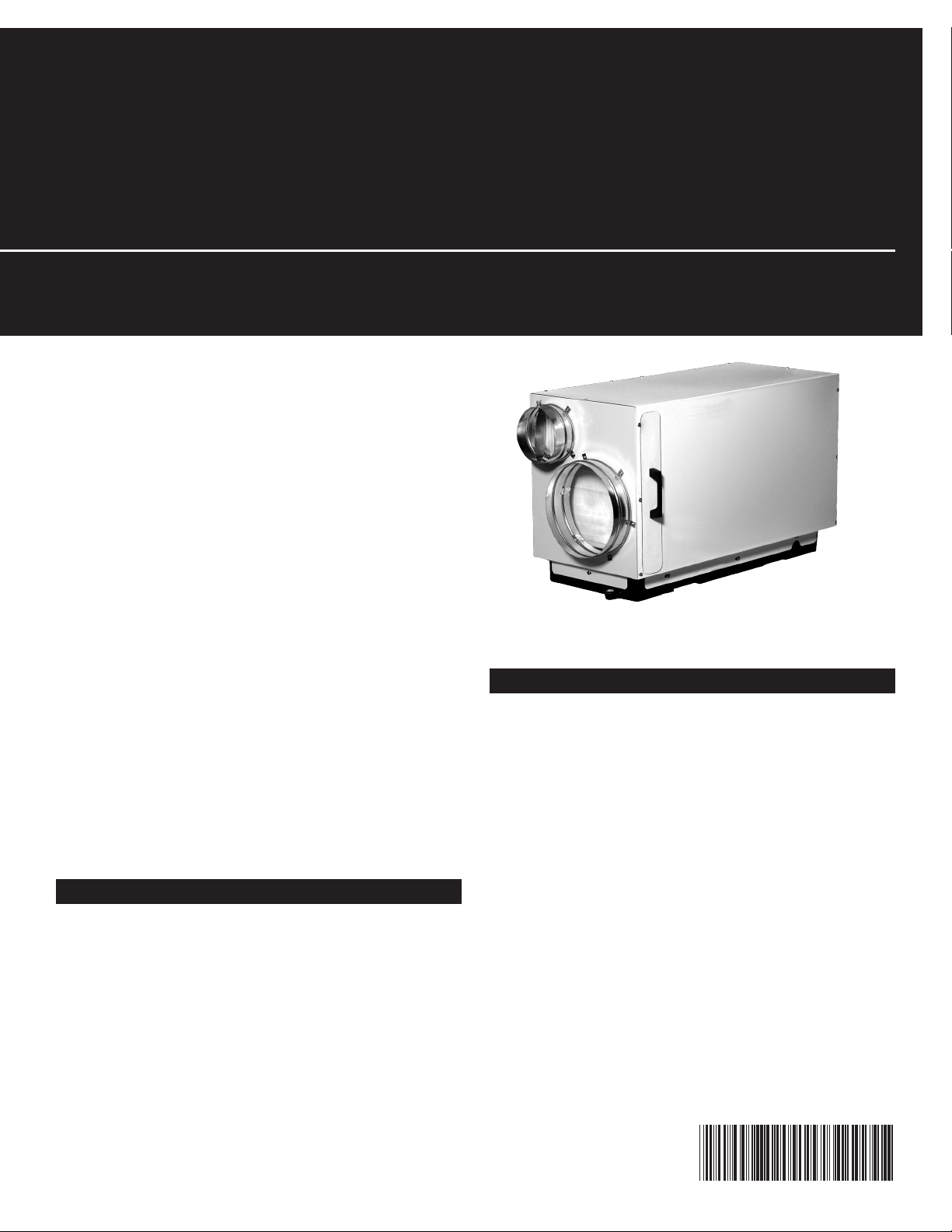
RXID-AW90A Whole House Dehumidifier
69-2298-01
Dehumidification
Fresh Air Ventilation
Compact Size
Energy Efficient
The whole house dehumidifier integrates highcapacity dehumidification, fresh air ventilation,
and filtration, into a compact and easy to install
enclosure.
with fresh air ventilation
Installation Guide
Fresh Air Ventilation (optional)
An automatic ventilation controller and dehumidistat are included.
The dehumidifier removes 90 pints of water from
the air per day (80F, 60% RH) while only using 6.2
Amps of electricity.
The high moisture removal capacity helps maintain proper levels of humidity in most homes.
Dehumidification
The dehumidifier's high efficiency refrigeration
system is further enhanced with a heat exchanger to
achieve exceptional performance while keeping your
energy costs as low as possible.
HVAC Installer: Please leave manual for homeowner.
Fresh air may be ducted to the unit and regulated
using an optional fresh air ventilation controller
along with a fresh air damper.

Dehumidifier • For HVAC Installer Only
Table of Contents
Introduction ....................... 1
Features & Benefits ................. 1
Safety Precautions .................. 2
1. Intended Application ................ 3
2. Approvals ......................... 3
3. Specifications ...................... 3
4. Installation ........................ 3
4.1 Installation Checklist ............. 3
4.1A Power Accessibility ......... 3
4.1B Accessibility ............... 3
4.1C Support Structure and
Suspension ................ 4
4.1D Sizing Chart ............... 4
4.2 Electrical Requirements ........... 4
4.3 Condensate Removal ............ 4
4.4 Ducting. . . . . . . . . . . . . . . . . . . . . . . . 4
4.4A Fresh Air / Supply Air ........ 4
4.4B Ducting for Fresh Air—Option . 5
4.4C Installation in a Basement or
Crawl Space with an Existing
Forced Air HVAC System ..... 5
4.4D Installation in an Attic with
an Existing Forced Air
HVAC System .............. 6
4.4E Installation in a Structure with
Two Forced Air HVAC Systems 7
4.5 Noise Abatement ................ 7
5. Maintenance ....................... 7
5.1 Air Filter ....................... 7
5.2 Optional Fresh Air Intake .......... 7
6. Wiring Diagrams .................... 7
7. Parts List ......................... 8
8. Service ........................... 8
8.1 Troubleshooting ................. 9
8.2 Refrigerant Charging ............ 10
8.3 Compressor/Capacitor
Replacement .................. 10
Safety Precautions
Read the installation, operation and maintenance instructions carefully before installing and
operating this device. Proper adherence to these instructions is essential to obtain maximum
benefit from your indoor air quality system.
READ AND SAVE THESE INSTRUCTIONS
• The device is designed to be installed INDOORS IN A SPACE THAT IS
PROTECTED FROM RAIN AND FLOODING.
• Install the unit with space to access the front panel for maintenance and
service.
• Avoid directing the discharge air at people, or over the water in pool areas.
• If used near a pool or spa; be certain there is NO chance the unit could fall
into the water, splashed and that it is plugged into a GFI GROUND FAULT
INTERRUPT OUTLET.
• DO NOT place the device directly on structural members.
• A drain pan MUST be placed under the unit if installed above a living area or
above an area where water leakage could cause damage.
69-2298—01 2
For HVAC Installer Only • Installation Guide
M28622
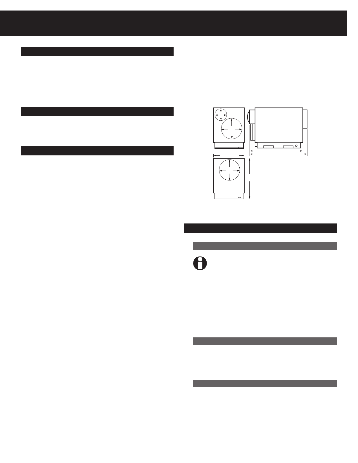
6
(152)
10
(254)
INLET VIEW
10
(254)
OUTLET VIEW
SIDE VIEW
15-3/4 (400)
20-7/8
(530)
34-1/2 (876)
43-1/2 (1092)
1. Intended Application for Dehumidifier
The dehumidifier is intended for use in residential
applications to reduce the indoor humidity levels
and increase comfort. With the optional ventilation
ducting and ventilation control hookup, the device
also provides precise amounts of ventilation air.
2. Approvals
The dehumidifier is certified by ETL to meet UL 474
and CSA 22.2 No. 92.
3. Specifications
Model: RXID-AW9A
Electrical: 110-120 VAC, 6.3 Amps,
60 Hz, grounded
Capacity: 97 Pints/Day (80ºF [27ºC],
60% RH)
114 Pints/Day (90ºF
[32ºC], 60% RH)
130 Pints/Day (100ºF
[38ºC], 60% RH)
Blower: 240 CFM @ 0.0 in. WG
220 CFM @ 0.4 in. WG
Unit Weight: 92 lbs
Shipping Size: 42"L x 25.875"H x 20.5"W
Weight: 99 lbs
Power Cord: 7.5 ft, 115V With Ground
Drain Connection: 3/4 in. Threaded MPT
Figure 1: Dimensions.
4. Installation
4.1 Installation Checklist
Coverage (sq ft): Up to 2800
Inlet air temperature range: 55°F min., 100°F max.
Operating Exterior Temp: 56-130ºF (13-54ºC) ducted
Air Flow: 200 CFM without external
Discharge Air Temp: 105ºF (41ºC) (80ºF [27ºC],
Refrigerant Charge: 1 lb., 12 oz. R22
Duct Connections: 6 in. Round Inlet
Filter Size: Pleated MERV 11:
Filter Efficiency: Standard MERV-11 (65%
Unit Size: 34.5"L (w/o Duct Collars) ;
3 69-2298—01
56-100ºF (13-38ºC)
unducted
ducting
60% RH intake)
10 in. Round Inlet
10 in. Round Outlet
14" x 14" x 1"
ASHRAE Dust Spot)
40.5"L (w/ Duct Collars)
x 15.75"W x 20.875"H
(See Fig. 1)
IMPORTANT: Prior to installation of the
dehumidifier, the following checklist should
be reviewed.
The dehumidifier can be installed in a variety of
locations to meet the owner’s needs, and integrate
with existing forced air systems or existing ductwork
if desired. Choose a location with consideration
to accessibility for service, drain availability, and
power outlet location.
4.1A Power Accessibility
Unit should be located in an area where the cord’s
length (10') should easily reach a 115 VAC electrical
outlet with a minimum of a 15 A circuit capacity.
4.1B Accessibility
The installed dehumidifier should have at least 14
inches of clearance in the front of the device to
service the filter.
Dehumidifier • For HVAC Installer Only
Place the dehumidifier on supports to raise the
base of the unit. Do not place the dehumidifier
directly on structural building members without
vibration absorbers or unwanted noise may result.
The dehumidifier may be suspended from structural
members by supporting the entire base of the unit
via cross members, rigid frame, or the like. Do
not hang the dehumidifier from the cabinet.
Remember to place a drain pan under the unit if
it is suspended above a finished area or above an
area where water leakage could cause damage.
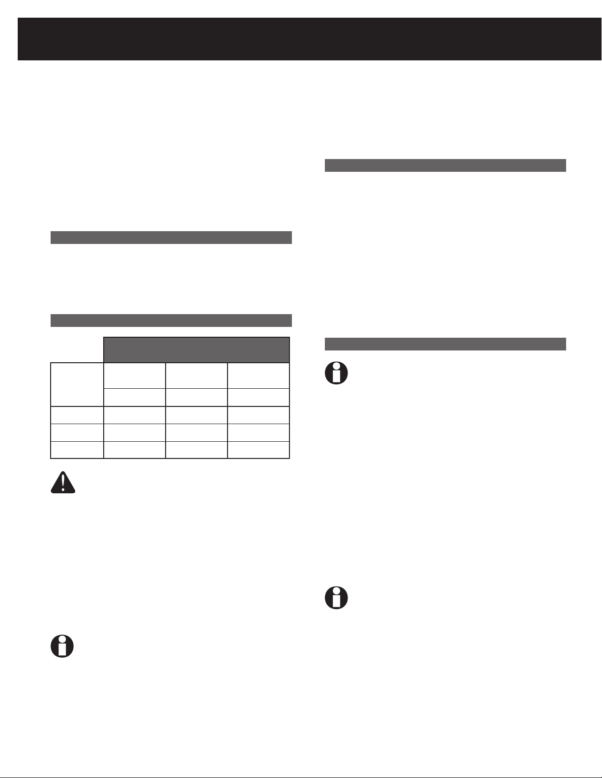
4.1D Sizing Chart
*This sizing chart is based on extreme climates where
Rh levels are between 70 and 90% outdoor Rh. For
less extreme climates then larger homes can be
adequately served. Actual requirements may vary.
4.2 Electrical Requirements
Dehumidifier Capacity Required to
Maintain Desired Indoor Rh*
Home Size
(square
feet)
2080 49-54 55-58 71-78
60% Indoor Rh55% Indoor Rh50% Indoor
Rh
Pints/day Pints/day Pints/day
Refer to Section 6 for typical hookup diagrams.
Some of the control wires leaving the dehumidifier
may not be used with certain installations and
should be left unconnected with wire nuts taped
onto the stripped ends for safety.
4.3 Condensate (Water) Removal
The dehumidifier removes a large amount of moisture
from the air and the device must be connected to a
drain line that will carry away the excess water. A
trap in the drain line is recommended and may be
required by some local codes.
The drain line should be connected to the 3/4"
male pipe thread adaptor on the front of the
dehumidifier.
Care should be taken to install the drain line with
a continuous slope of 1" per 10' to assure proper
water removal.
4.4 Ducting
IMPORTANT: When connecting ventilation
duct, remove the label and 6" round
insulation plug from the ventilation duct
opening. If not using ventilation feature,
leave the insulation intact.
2600 61-68 65-72 90-97
3120 75-82 79-86 95-110
WARNING: Installation must be performed
by a qualified service technician and must
comply with local codes. Remove power to
the device before installing or servicing the
device. Failure to connect the device
according to these instructions may result in
damage to the device or the controls.
The dehumidifier plugs into a common grounded
115VAC outlet. The device draws 6.3 Amps under
normal operating conditions. If used in an area
which may become wet, a ground fault interrupter
(GFI) protected circuit is recommended.
IMPORTANT: Do not install the humidistat
where it may not accurately sense the relative
humidity such as near HVAC supply registers,
near exterior doors, on an outside wall, near
a window, or near a water source.
For the ideal installation, draw air from the central
part of the home and return it to the isolated areas
of the home like the bedrooms, den, utility room, or
family room. See Figure 2. Alternative installation
option can be completed by drawing air directly
from the return ducting and distributing through
the supply air to the home.
Another installation option is ducting directly from
the return and distributing directly back into the
system's return. See Figure 3. Fresh air ventilation
is optional and does not have to be ducted in order
for the dehumidifier to properly function.
IMPORTANT: DO NOT draw air directly from
the kitchen, laundry, or isolated basement.
Air may be drawn from a basement that is open
to the home. All flexible ducting connected to the
dehumidifier should be UL listed.
A short piece of flexible ducting on all dehumidifier
duct connections is recommended to reduce noise
and vibration transmitted to rigid ductwork in the
structure. Ducting the dehumidifier as mentioned
requires consideration of the following points:
69-2298—01 4
 Loading...