

Rheem RXHK-A01 Installation Instructions Manual
FLOAT SAFETY SWITCH
RXHK-A01
RECOGNIZE THIS SYMBOL AS AN INDICATION OF IMPORTANT SAFETY
!
INFORMATION!
!
WARNING
THESE INSTRUCTIONS ARE INTENDED AS AN AID TO QUALIFIED SERVICE PERSONNEL FOR PROPER INSTALLATION,
ADJUSTMENT AND OPERATION OF THIS UNIT. READ THESE INSTRUCTIONS THOROUGHLY BEFORE ATTEMPTING
INSTALLATION OR OPERATION. FAILURE TO FOLLOW THESE INSTRUCTIONS MAY RESULT IN IMPROPER INSTALLATION,
ADJUSTMENT, SERVICE OR MAINTENANCE, POSSIBLY RESULTING IN FIRE, ELECTRICAL SHOCK, CARBON MONOXIDE
POISONING, EXPLOSION, PROPERTY DAMAGE, PERSONAL INJURY OR DEATH.
FLOAT SAFETY SWITCH RXHK-A01
The float safety switch is design to shut off power off to the outdoor unit in the event of condensate drain blockage. This will in
turn help to prevent any water or structural damage to the surrounding areas of the air handler.
INSTALLATION INSTRUCTIONS:
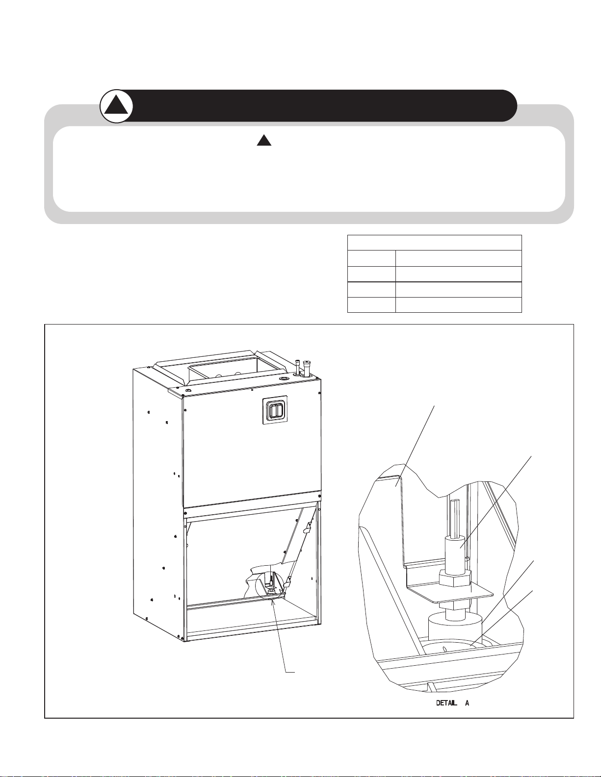
FIGURE 1
Parts List
Qty.
1
1 Zip Tie
2
Description
Float Safety Switch
Wire Nut
DRAIN PAN
OVERFLOW
SWITCH
FLOAT SWITCH
LOCATION
MAKE
SURE BULB
CAN MOVE
FREELY
SECONDARY
DRAIN
92-103404-01-00
1. Disconnect all power from to the indoor and outdoor unit.
2. Remove the blower door panel from the air handler and remove the control box cover from the outdoor unit.
3. Insert the float safety switch into the designated area located
on the drain pan. Make sure that the bulb can travel freely in
the vertical direction and is leveled properly. Reference figure
1 for more detail.
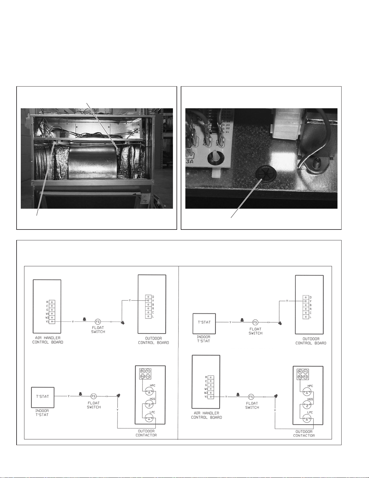
4. Route the wiring harness of the float safety switch along the
side of the suction tube of the front return air handler. Zip tie
the wiring harness near the top of the suction tube and feed
the remaining wire through the star bushing provided on the
blower shelf of the air handler. Reference Figures 2 & 3.
5. Verify which indoor and outdoor unit that you have and connect the electrical wiring as shown in Figure 4.
6. Reinstall indoor blower door panel and outdoor control box
cover.
7. Reconnect power.
FIGURE 2
ROUTEWIRETHROUGH STAR
BUSHING. SEE FIGURE 3
ROUTEWIRE IN FRONT OF
BLOWER CLOSE TO BOTTOM
OF BLOWER SHELF
FIGURE 4
FLOAT SWITCH WIRING DIAGRAM
FIGURE 3
ROUTEWIRETHROUGH
STARBUSHING
HP OUTDOOR MATCHED WITH RHBL INDOOR HP OUTDOOR MATCHED WITH RHAL INDOOR
AC OUTDOOR MATCHED WITH RHBL INDOOR
AC OUTDOOR MATCHED WITH RHAL INDOOR
CM 0110
 Loading...